WO2022230357A1 - 熱拡散デバイス - Google Patents
熱拡散デバイス Download PDFInfo
- Publication number
- WO2022230357A1 WO2022230357A1 PCT/JP2022/009152 JP2022009152W WO2022230357A1 WO 2022230357 A1 WO2022230357 A1 WO 2022230357A1 JP 2022009152 W JP2022009152 W JP 2022009152W WO 2022230357 A1 WO2022230357 A1 WO 2022230357A1
- Authority
- WO
- WIPO (PCT)
- Prior art keywords
- wall surface
- vapor chamber
- capillary structure
- housing
- wick
- Prior art date
- Legal status (The legal status is an assumption and is not a legal conclusion. Google has not performed a legal analysis and makes no representation as to the accuracy of the status listed.)
- Ceased
Links
Images


Classifications
-
- F—MECHANICAL ENGINEERING; LIGHTING; HEATING; WEAPONS; BLASTING
- F28—HEAT EXCHANGE IN GENERAL
- F28D—HEAT-EXCHANGE APPARATUS, NOT PROVIDED FOR IN ANOTHER SUBCLASS, IN WHICH THE HEAT-EXCHANGE MEDIA DO NOT COME INTO DIRECT CONTACT
- F28D15/00—Heat-exchange apparatus with the intermediate heat-transfer medium in closed tubes passing into or through the conduit walls ; Heat-exchange apparatus employing intermediate heat-transfer medium or bodies
- F28D15/02—Heat-exchange apparatus with the intermediate heat-transfer medium in closed tubes passing into or through the conduit walls ; Heat-exchange apparatus employing intermediate heat-transfer medium or bodies in which the medium condenses and evaporates, e.g. heat pipes
- F28D15/04—Heat-exchange apparatus with the intermediate heat-transfer medium in closed tubes passing into or through the conduit walls ; Heat-exchange apparatus employing intermediate heat-transfer medium or bodies in which the medium condenses and evaporates, e.g. heat pipes with tubes having a capillary structure
-
- H—ELECTRICITY
- H10—SEMICONDUCTOR DEVICES; ELECTRIC SOLID-STATE DEVICES NOT OTHERWISE PROVIDED FOR
- H10W—GENERIC PACKAGES, INTERCONNECTIONS, CONNECTORS OR OTHER CONSTRUCTIONAL DETAILS OF DEVICES COVERED BY CLASS H10
- H10W40/00—Arrangements for thermal protection or thermal control
- H10W40/70—Fillings or auxiliary members in containers or in encapsulations for thermal protection or control
- H10W40/73—Fillings or auxiliary members in containers or in encapsulations for thermal protection or control for cooling by change of state
Definitions
- the present invention relates to heat diffusion devices.
- the vapor chamber has a structure in which a working medium and a wick that transports the working medium by capillary force are sealed inside the housing.
- the working medium absorbs heat from the heating element in the evaporating section that absorbs heat from the heating element, evaporates in the vapor chamber, moves to the condensing section, is cooled, and returns to the liquid phase.
- the working medium that has returned to the liquid phase moves again to the evaporating portion on the heating element side by the capillary force of the wick, and cools the heating element.
- the vapor chamber can operate independently without external power, and heat can be two-dimensionally diffused at high speed by utilizing the latent heat of vaporization and latent heat of condensation of the working medium.
- Patent Literature 1 discloses a vapor chamber in which a peripheral fluid passage portion through which the working fluid flows is formed over the entire peripheral edge of the first metal sheet or the second metal sheet.
- a liquid flow path portion (wick) through which the liquid working fluid passes is formed on the entire surface of the vapor chamber when viewed from above (see FIG. 4 of Patent Document 1). Further, the shape of the wick is shown on the premise that the shape of the vapor chamber when viewed from above is rectangular, and the heat source is positioned at the center of the rectangle (see each figure of Patent Document 1).
- the wick is formed on the entire surface of the vapor chamber when viewed from above, the proportion of the vapor flow path through which the vapor of the working fluid passes is relatively reduced. A problem arises that the maximum heat transfer rate decreases when the percentage of the portion through which the steam passes is low. In addition, since the steam flow path is divided by the wick, there arises a problem that uniformity of heat is lowered. Furthermore, forming the wick on the entire surface also raises the problem that the cost associated with the formation of the wick increases.
- the wick instead of forming the wick over the entire surface, it is being considered to form the wick only where it is considered necessary. This is the case where the wick is not formed on the entire surface, and the shape of the vapor chamber when viewed from above is not a rectangle, but a shape having first and second sides forming an interior angle of 180° or more (hereinafter also referred to as a deformed shape).
- a liquid pool may occur near the first side or the second side. Liquid pools formed near the first side or the second side cannot be collected by the wick, so the amount of liquid transported is reduced, resulting in a problem of a decrease in the maximum heat transport amount.
- the present invention has been made to solve the above problems, and provides a heat diffusion device that can increase the maximum heat transfer rate and heat uniformity by increasing the ratio of steam flow paths.
- the purpose is to
- a heat diffusion device of the present invention includes a housing having an internal space, a working medium enclosed in the internal space, and a wick arranged in the internal space, wherein the housings face each other in a thickness direction.
- the first inner wall surface and the second inner wall surface are joined to form a sealing portion that serves as a boundary of the inner space, and the wick comprises: Along the direction perpendicular to the thickness direction, there is a portion in contact with the first inner wall surface and the second inner wall surface of the housing, and a steam flow path is formed in the internal space of the housing.
- the sealing portion has a first side and a second side forming an interior angle of 180° or more, and a capillary structure is formed along the first side. ing.
- FIG. 1 is a perspective view schematically showing an example of the vapor chamber according to the first embodiment of the invention.
- FIG. 2 is a cross-sectional view of the vapor chamber shown in FIG. 1 taken along the line AA.
- 3 is a cross-sectional view taken along line BB of FIG. 2.
- FIG. 4A is a cross-sectional view taken along line CC of FIG. 2.
- FIG. 4B is an enlarged view of the dashed line portion of FIG. 4A.
- FIG. 5A is a cross-sectional view schematically showing an example of the capillary structure of the vapor chamber according to the first embodiment of the invention.
- FIG. 5B is a cross-sectional view schematically showing an example of the capillary structure of the vapor chamber according to the first embodiment of the invention.
- FIG. 5C is a cross-sectional view schematically showing an example of the capillary structure of the vapor chamber according to the first embodiment of the invention.
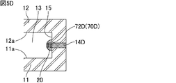
- FIG. 5D is a cross-sectional view schematically showing an example of the capillary structure of the vapor chamber according to the first embodiment of the present invention;
- FIG. 5E is a cross-sectional view schematically showing an example of the capillary structure of the vapor chamber according to the first embodiment of the present invention;
- FIG. 5F is a cross-sectional view schematically showing an example of the capillary structure of the vapor chamber according to the first embodiment of the invention.
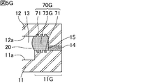
- 5G is a cross-sectional view schematically showing an example of the capillary structure of the vapor chamber according to the first embodiment of the present invention.
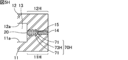
- FIG. 5H is a cross-sectional view schematically showing an example of the capillary structure of the vapor chamber according to the first embodiment of the present invention
- FIG. 5I is a cross-sectional view schematically showing an example of the capillary structure of the vapor chamber according to the first embodiment of the invention
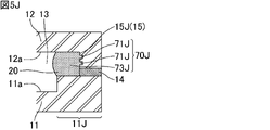
- FIG. 5J is a cross-sectional view schematically showing an example of the capillary structure of the vapor chamber according to the first embodiment of the invention.
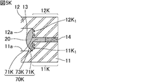
- FIG. 5K is a cross-sectional view schematically showing an example of the capillary structure of the vapor chamber according to the first embodiment of the present invention
- FIG. 5L is a cross-sectional view schematically showing an example of the capillary structure of the vapor chamber according to the first embodiment of the present invention;
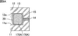
- FIG. 6A is a cross-sectional view schematically showing an example of the capillary structure of the vapor chamber according to the second embodiment of the invention.
- FIG. 6B is a cross-sectional view schematically showing an example of the capillary structure of the vapor chamber according to the second embodiment of the invention.
- FIG. 6C is a cross-sectional view schematically showing an example of the capillary structure of the vapor chamber according to the second embodiment of the invention.
- FIG. 7 is a cross-sectional view schematically showing an example of the capillary structure of the vapor chamber according to the third embodiment of the invention.
- FIG. 8 is a cross-sectional view schematically showing an example of the capillary structure of the vapor chamber according to the fourth embodiment of the invention.
- FIG. 6A is a cross-sectional view schematically showing an example of the capillary structure of the vapor chamber according to the second embodiment of the invention.
- FIG. 6B is a cross-sectional view schematically showing an example of the capillary
- FIG. 9A is a cross-sectional view schematically showing an example of the vapor chamber of the present invention having a different planar shape.
- FIG. 9B is a cross-sectional view schematically showing an example of the vapor chamber of the present invention having a different planar shape.
- FIG. 9C is a cross-sectional view schematically showing an example of the vapor chamber of the present invention having a different planar shape.
- FIG. 9D is a cross-sectional view schematically showing an example of the vapor chamber of the present invention having a different planar shape.
- FIG. 9E is a cross-sectional view schematically showing an example of the vapor chamber of the present invention having a different planar shape.
- the heat diffusion device of the present invention will be described below.
- the present invention is not limited to the following configurations, and can be appropriately modified and applied without changing the gist of the present invention. It should be noted that a combination of two or more of the individual preferred configurations of the invention described below is also the invention.
- a heat diffusion device of the present invention includes a housing having an internal space, a working medium enclosed in the internal space, and a wick arranged in the internal space, wherein the housings face each other in a thickness direction.
- the first inner wall surface and the second inner wall surface are joined to form a sealing portion that serves as a boundary of the inner space, and the wick comprises: Along the direction perpendicular to the thickness direction, there is a portion in contact with the first inner wall surface and the second inner wall surface of the housing, and a steam flow path is formed in the internal space of the housing.
- the sealing portion has a first side and a second side forming an interior angle of 180° or more, and a capillary structure is formed along the first side. ing.
- capillary structure means a structure that can transport a liquid-phase working medium by capillary force and does not divide the vapor flow path, and its shape is not particularly limited.
- FIG. 1 is a perspective view schematically showing an example of a vapor chamber, which is a heat diffusion device according to a first embodiment of the invention.
- the vapor chamber 1 shown in FIG. 1 includes a hollow housing 10 that is hermetically sealed.
- a heat source HS which is a heating element, is arranged on the outer wall surface of the housing 10 .
- the heat source HS include electronic components of electronic equipment, such as a central processing unit (CPU).
- the vapor chamber 1 is planar as a whole. That is, the housing 10 is planar as a whole.
- the “planar shape” includes a plate shape and a sheet shape, and the dimension in the width direction X (hereinafter referred to as width) and the dimension in the length direction Y (hereinafter referred to as length) are the thickness direction Z
- width width
- length dimension in the length direction
- Z It means a shape that is considerably large with respect to its dimensions (hereafter referred to as thickness or height). For example, it means a shape whose width and length are 10 times or more, preferably 100 times or more, the thickness.
- the size of the vapor chamber 1, that is, the size of the housing 10 is not particularly limited.
- the width and length of the vapor chamber 1 can be appropriately set according to the application.
- the width and length of the vapor chamber 1 are, for example, 5 mm or more and 500 mm or less, 20 mm or more and 300 mm or less, or 50 mm or more and 200 mm or less.
- the width and length of the vapor chamber 1 may be the same or different.
- the width and length of the vapor chamber are defined as maximum values in the width direction and the length direction.
- the housing 10 is preferably composed of a first sheet 11 and a second sheet 12 that face each other and whose outer edges are joined. Also, the first sheet 11 and the second sheet 12 are joined by brazing material 14 .
- Materials for the first sheet 11 and the second sheet 12 are not particularly limited as long as they have properties suitable for use as a vapor chamber, such as thermal conductivity, strength, softness, and flexibility.
- the material that constitutes the first sheet 11 and the second sheet 12 is preferably a metal, such as copper, nickel, aluminum, magnesium, titanium, iron, or an alloy containing them as a main component, and copper is particularly preferable. is.
- the materials forming the first sheet 11 and the second sheet 12 may be the same or different, but are preferably the same.
- the housing 10 is composed of the first sheet 11 and the second sheet 12
- the first sheet 11 and the second sheet 12 are joined together at their outer edges.
- Such joining method is joining using brazing material.
- the thicknesses of the first sheet 11 and the second sheet 12 are not particularly limited, but each is preferably 10 ⁇ m or more and 200 ⁇ m or less, more preferably 30 ⁇ m or more and 100 ⁇ m or less, still more preferably 40 ⁇ m or more and 60 ⁇ m or less.
- the thicknesses of the first sheet 11 and the second sheet 12 may be the same or different. Also, the thickness of each sheet of the first sheet 11 and the second sheet 12 may be the same over the entire area, or may be thin in part.
- first sheet 11 and the second sheet 12 are not particularly limited.
- first sheet 11 may have a flat plate shape with a constant thickness
- second sheet 12 may have a shape in which the outer edge portion is thicker than the portions other than the outer edge portion.
- the first sheet 11 may have a flat plate shape with a constant thickness
- the second sheet 12 may have a constant thickness and a portion other than the outer edge with respect to the outer edge may be convex outward. good.
- a recess is formed in the outer edge of the housing 10 . Therefore, the concave portion of the outer edge can be used when mounting the vapor chamber. Also, other components can be placed in the recesses of the outer edge.
- the thickness of the entire vapor chamber 1 is not particularly limited, it is preferably 50 ⁇ m or more and 500 ⁇ m or less.
- the planar shape of the housing 10 seen from the thickness direction Z shown in FIG. 1 is L-shaped.
- the planar shape of the housing is not particularly limited as long as the internal angle formed by the first side and the second side is 180° or more. shape), T-shape, stepped shape, and the like.
- the housing 10 may have a space (through-hole) inside the planar figure (that is, square shape).
- the planar shape of the housing 10 may be a shape according to the use of the vapor chamber, the shape of the location where the vapor chamber is installed, and other parts existing nearby.
- FIG. 2 is a cross-sectional view of the vapor chamber shown in FIG. 1 taken along the line AA.
- 3 is a cross-sectional view taken along line BB of FIG. 2.
- housing 10 having interior space 13 includes working medium 20 enclosed in interior space 13 and wick 35 arranged in interior space 13 .
- the housing 10 has a first inner wall surface 11a and a second inner wall surface 12a facing each other in the thickness direction Z. They are joined to form a sealing portion 15 that bounds the internal space 13 .
- the wick 35 extends in a direction perpendicular to the thickness direction Z and has portions in contact with the first inner wall surface 11 a and the second inner wall surface 12 a of the housing 10 .
- the wick 35 includes a first porous body 41 and a second porous body 42 . These porous bodies have the function of transporting the working medium 20 by capillary force. Also, the first porous body 41 and the second porous body 42 that constitute the wick 35 have portions in contact with the first inner wall surface 11 a and the second inner wall surface 12 a of the housing 10 . By arranging these porous bodies in the internal space 13 of the housing 10, it is possible to absorb impacts from outside the housing 10 while ensuring the mechanical strength of the housing 10. FIG. The thickness of the first porous body 41 and the second porous body 42 forming the wick 35 is approximately the same as the thickness of the internal space 13 of the housing 10 . A vapor flow path 50 through which the vapor-phase working medium 20 flows is formed in the internal space 13 of the housing 10 .
- the direction in which the first porous body 41 and the second porous body 42 extend is between the first porous body 41 and the second porous body 42.
- a liquid pool flow path 51 is formed by further providing an interval along the width direction X).
- the liquid pool channel 51 can be used as a liquid channel through which the liquid-phase working medium 20 flows.
- the housing 10 is provided with an evaporation portion EP for evaporating the enclosed working medium 20 .
- a portion of the internal space 13 of the housing 10 that is in the vicinity of the heat source HS and is heated by the heat source HS corresponds to the evaporating portion EP.
- the working medium 20 is not particularly limited as long as it can cause a gas-liquid phase change in the environment inside the housing 10.
- water, alcohols, CFC alternatives, etc. can be used.
- the working medium is an aqueous compound, preferably water.
- the wick 35 extends from one end located in the evaporating part EP to the other end in plan view from the thickness direction Z. As shown in FIG. The other end is a portion away from the evaporator EP and serves as a condensing portion for condensing the evaporated working medium.
- the planar shape of the housing 10 is a so-called L shape.
- the sealing portion 15 has a first side 61 and a second side 62 forming an interior angle of 180° or more.
- the internal angle between the first side 61 and the second side 62 is the angle ⁇ in FIG. 2, which is 270° in this drawing.
- the first side 61 is a side located farther from the evaporating part EP than the second side 62 is.
- the wick 35 is not formed in the vicinity of the first side 61 and the second side 62, and from the shape of the housing 10, the direction in which the vapor chamber 1 is used (the direction with respect to the direction in which gravity is applied) Depending on the situation, liquid puddles may occur near the first side 61 and the second side 62 . Therefore, in the housing 10 , the capillary structure 70 is formed along the first side 61 and the second side 62 . Due to the existence of the capillary structure 70, the liquid puddles generated in the vicinity of the first side 61 and the second side 62 can be transported to the evaporating part EP. As a result, the amount of liquid transported can be improved, and the maximum heat transport amount can be improved.
- the capillary structure will be described in detail below.
- the capillary structure 70 is a liquid channel through which the liquid-phase working medium 20 flows, but is different from the wick 35 . Since the wick 35 is in contact with both the first inner wall surface 11a and the second inner wall surface 12a, it is configured to divide the steam flow path. On the other hand, the capillary structure 70 is configured so as not to divide the vapor flow path.
- FIG. 4A is a cross-sectional view taken along line CC of FIG. 2.
- FIG. FIG. 4B is an enlarged view of the dashed line portion of FIG. 4A. That is, FIG. 4B is a cross-sectional view of the vicinity of the sealing portion 15 that forms the first side 61 in the vapor chamber 1.
- FIGS. 4A and 4B in the housing 10 , the first inner wall surface 11 a and the second inner wall surface 12 a are joined with brazing material 14 to form a sealing portion 15 .
- brazing material conventionally known brazing materials can be used, and examples thereof include solder, copper, silver, copper alloys, phosphorous copper, and the like.
- a plurality of recesses 71 are formed in the first inner wall surface 11a and the second inner wall surface 12a in the vicinity of the sealing portion 15, which constitute a capillary structure 70.
- the concave portion 71 forming the capillary structure 70 may have any shape as long as it can transport the liquid-phase working medium 20 by capillary force.
- the recess 71 shown in FIG. 4B is formed by a bottom surface and two walls perpendicular to the bottom surface. It may be V-shaped, or it may be U-shaped.
- the concave portions 71 may be formed by etching or the like after the first sheet 11 and the second sheet 12 are formed.
- the width of the concave portion 71 is not particularly limited as long as the liquid-phase working medium can be transported by capillary force, but is preferably 2 ⁇ m or more and 200 ⁇ m or less. Moreover, the depth of the concave portion 71 is preferably 2 ⁇ m or more and 200 ⁇ m or less.
- the capillary structure 70 is formed on both the first inner wall surface 11a and the second inner wall surface 12a. It is sufficient that a capillary structure is formed on one side.
- a capillary structure 70 is formed along the first side 61 and the second side 62 in the vapor chamber 1 . Therefore, even if a liquid pool occurs in the vicinity of the first side 61 or the second side 62, the capillary structure 70 can transport the liquid-phase working medium 20 to the evaporating part EP. That is, it is possible to solve the problem that the maximum amount of heat transport is reduced due to the influence of the liquid pool generated at the position where the wick 35 is not formed.
- the wick 35 has a first end 35a and a second end 35b. It faces the sealing portion 15 forming the third side 63 other than the second side 62 , and the capillary structure 70 is not formed along the third side 63 .
- the wick 35 can transport the working medium 20 to the evaporating section EP. That is, in the vapor chamber 1 , the working medium 20 can be transported even if the capillary structure 70 is not formed along the third side 63 .
- the capillary structure may not be formed along all sides formed by the sealing portion. If the capillary structure is formed along the entire side formed by the sealing portion, the vapor-phase working medium 20 is less likely to move to the capillary structure 70 portion, and the maximum heat transfer rate tends to decrease. However, if there is a portion where the capillary structure is not formed, the vapor-phase working medium tends to move to the portion where the capillary structure is not formed, so that the maximum heat transfer rate is less likely to decrease. Also, by not forming a capillary structure, the manufacturing cost of the vapor chamber can be reduced.
- a capillary structure may be formed along all sides formed by the sealing portion.
- 5A to 5L are cross-sectional views schematically showing an example of the capillary structure of the vapor chamber according to the first embodiment of the invention.
- a capillary structure 70A is formed by recesses 71A.
- the recess 71A may be formed by applying the brazing material 14A between the first inner wall surface 11a and the second inner wall surface 12a with a dispenser so that the exposed surface of the brazing material 14A is uneven. After bonding the first inner wall surface 11a and the second inner wall surface 12a, the exposed surface of the brazing material 14A may be corroded by etching or the like.
- the structure of the capillary structure 70B and its vicinity shown in FIG. 5B has no recesses formed in the first inner wall surface 11a and the second inner wall surface 12a, and the vicinity of the surface of the brazing material 14B exposed in the internal space 13 is porous. It is the same as the structure in the vicinity of the capillary structure 70 except that it is 72B.
- a capillary structure 70B is formed by a porous body 72B.
- the porous body 72B is formed by arranging a member that becomes porous by heating in the vicinity of the exposed surface of the brazing material 14B when arranging the brazing material 14B on the first inner wall surface 11a and the second inner wall surface 12a. can be formed by performing
- a member that becomes porous by heating is, for example, metal powder, ceramic powder, or the like.
- these members are included in the brazing material 14B, these members are sintered during brazing to form a metal porous sintered body and a ceramic porous sintered body.
- the capillary structure 70C shown in FIG. 5C and its vicinity recesses are not formed in the first inner wall surface 11a and the second inner wall surface 12a, and an internal space is formed between the first inner wall surface 11a and the second inner wall surface 12a.
- the structure is the same as the structure in the vicinity of the capillary structure 70 except that the porous body 72C exposed at 13 and the brazing material 14C are arranged inside thereof.
- a porous body 72C forms a capillary structure 70C.
- the porous body 72C is formed by arranging and brazing the brazing material 14C so that a gap connecting to the internal space 13 is formed between the first inner wall surface 11a and the second inner wall surface 12a, and then heating the gap to form a porous body. It can be formed by arranging and heating the members to be.
- Examples of such a porous body 72C include a metal porous sintered body, a ceramic porous sintered body, and the like.
- the structure of the capillary structure 70D and its vicinity shown in FIG. 5D does not have recesses formed in the first inner wall surface 11a and the second inner wall surface 12a, and the porous body 72D is formed in the inner space 13 so as to be in contact with the brazing material 14D. It is the same as the structure in the vicinity of the capillary structure 70 except that it is formed.
- a porous body 72D forms a capillary structure 70D.
- the porous body 72D is formed by brazing the first inner wall surface 11a and the second inner wall surface 12a with the brazing filler metal 14D, and then placing a member that becomes a porous body by heating on the brazing filler metal 14D and heating it. can be done.
- Examples of such a porous body 72D include a metal porous sintered body, a ceramic porous sintered body, and the like.
- the capillary structure 70E shown in FIG. 5E and the structure in the vicinity thereof recesses are not formed in the first inner wall surface 11a and the second inner wall surface 12a, and the first sheet 11 near the sealing portion 15 covers the thick wall region 11E.
- the structure in the vicinity of the capillary structure 70 is the same except that a narrow space 73E is formed between the first inner wall surface 11a and the second inner wall surface 12a located in the thick wall region 11E.
- narrow spaces 73E form capillary structures 70E.
- the narrow space 73E can be formed by preparing in advance the first sheet 11 having the thick wall region 11E.
- the width of the narrow space 73E (the distance from the first inner wall surface 11a to the second inner wall surface 12a) is not particularly limited as long as the liquid-phase working medium can be transported by capillary force, but is preferably 2 ⁇ m or more and 200 ⁇ m or less. Also, the depth of the narrow space 73E is preferably 2 ⁇ m or more and 200 ⁇ m or less.
- the capillary structure 70F and its vicinity shown in FIG. 5F recesses are not formed in the first inner wall surface 11a and the second inner wall surface 12a, and the first sheet 11 near the sealing portion 15 covers the thick wall region 11F.
- the second sheet 12 near the sealing portion 15 has a thick-wall region 12F, and is between the first inner wall surface 11a located in the thick-wall region 11F and the second inner wall surface 12a located in the thick-wall region 12F.
- the structure is the same as the structure in the vicinity of the capillary structure 70 except that a narrow space 73F is formed at the end.
- narrow spaces 73F form capillary structures 70F.
- the narrow space 73F can be formed by preparing in advance the first sheet 11 having the thick wall region 11F and the second sheet having the thick wall region 12F.
- the first sheet 11 in the vicinity of the sealing portion 15 has the thick wall region 11G, and the first inner wall surface 11a and the second inner wall surface 11a located in the thick wall region 11G. It has the same structure as the capillary structure 70 and its neighboring structure except that a narrow space 73G is formed between the capillary structure 70 and the structure 12a.
- narrow spaces 73G and recesses 71 form capillary structures 70G.
- the method of forming the narrow space 73G is the same as the method of forming the narrow space 73E. Since the method of forming the recess 71 has already been explained, the explanation is omitted here.
- the capillary structure 70H shown in FIG. 5H and the structure in the vicinity thereof the first sheet 11 near the sealing portion 15 has the thick-wall region 11H, and the second sheet 12 near the sealing portion 15 has the thick-wall region 12H.
- a narrow space 73H is formed between the first inner wall surface 11a located in the thick-wall region 11H and the second inner wall surface 12a located in the thick-wall region 12H
- the capillary structure 70 and its vicinity are Same as structure.
- narrow spaces 73H and recesses 71 form capillary structures 70H.
- the method of forming the narrow space 73H is the same as the method of forming the narrow space 73F. Since the method of forming the recess 71 has already been explained, the explanation is omitted here.
- recesses 71I form capillary structures 70I.
- the method for forming the recess 71I is the same as the method for forming the recess 71 described above.
- the capillary structure 70J shown in FIG. 5J and the structure in the vicinity thereof recesses are not formed in the first inner wall surface 11a and the second inner wall surface 12a, and the first sheet 11 in the vicinity of the sealing portion 15 covers the thick wall region 11J.
- a narrow space 73J is formed between the first inner wall surface 11a and the second inner wall surface 12a located in the thick wall region 11J, and the recess 71J is formed in the side surface 15J of the sealing portion 15 of the second sheet 12. It is the same as the structure in the vicinity of the capillary structure 70 except that it is formed.
- narrow spaces 73J and recesses 71J form capillary structures 70J.
- the method of forming the narrow space 73J is the same as the method of forming the narrow space 73E.
- the method for forming the recess 71J is the same as the method for forming the recess 71 described above.
- the first sheet 11 near the sealing portion 15 covers the thick wall region 11K.
- the second sheet 12 near the sealing portion 15 has a thick-wall region 12K, and is between the first inner wall surface 11a located in the thick-wall region 11K and the second inner wall surface 12a located in the thick-wall region 12K.
- a narrow space 73K is formed in the capillaries 11K and 12K1 of the thick-wall region 11K of the first sheet 11 and the side surface 12K-1 of the thick-wall region 12K of the second sheet 12, respectively. It is the same as the structure near the structure 70 .
- narrow spaces 73K and recesses 71K form capillary structures 70K.
- the method of forming the narrow space 73K is the same as the method of forming the narrow space 73F.
- the method for forming the recess 71K is the same as the method for forming the recess 71 described above.
- the structure of the capillary structure 70L and the vicinity thereof shown in FIG. 5L has no recesses on the first inner wall surface 11a and the second inner wall surface 12a, and has protrusions 74L. It is the same as the neighboring structure.
- the capillary structure 70L is formed by the projections 74L.
- the convex portion 74L can be formed by providing a convex shape in advance when the first sheet 11 and the second sheet 12 are manufactured.
- the convex portion 74L is formed by an upper surface and two walls perpendicular to the upper surface.
- the shape may be an inverted V shape, or an inverted U shape.
- the interval between the convex portions 74L is not particularly limited as long as the liquid-phase working medium can be transported by capillary force, but is preferably 2 ⁇ m or more and 200 ⁇ m or less. Also, the height of the convex portion 74L is preferably 2 ⁇ m or more and 200 ⁇ m or less.
- a vapor chamber which is a heat diffusion device according to a second embodiment of the present invention
- the vapor chamber according to the second embodiment of the invention is the same as the vapor chamber according to the first embodiment of the invention, except that a fiber bundle having capillary force is used as the capillary structure.
- a capillary structure of a vapor chamber according to a second embodiment of the present invention will be described below with reference to the drawings. 6A to 6C are cross-sectional views schematically showing an example of the capillary structure of the vapor chamber according to the second embodiment of the invention.
- a fiber bundle 175A forms a capillary structure 170A.
- the fiber bundle is not particularly limited, but a braided fiber bundle can be used.
- the fibers for example, metal wires such as copper, aluminum, and stainless steel wires, and non-metal wires such as carbon fibers and glass fibers can be used.
- a metal wire is preferable because of its high thermal conductivity.
- a fiber bundle can be obtained by bundling about 200 copper wires with a diameter of about 0.03 mm.
- capillary structure 170B and its vicinity shown in FIG. 6B is the same as the structure of the capillary structure 70E and its vicinity except that the fiber bundle 175B is formed in the vicinity of the sealing portion 15.
- FIG. 6B capillary structure 170A is formed by narrow space 73E and fiber bundle 175B.
- the structure of the capillary structure 170C and its vicinity shown in FIG. 6C is the same as the structure of the capillary structure 70F and its vicinity except that the fiber bundle 175C is formed in the vicinity of the sealing portion 15.
- FIG. 6C narrow spaces 73F and fiber bundles 175C form capillary structures 170C.
- FIG. 7 is a cross-sectional view schematically showing an example of a capillary structure according to a third embodiment of the vapor chamber of the invention.
- the method of joining the first inner wall surface 11a and the second inner wall surface 12a is not particularly limited, but for example, laser welding, resistance welding, diffusion bonding, TIG welding (tungsten-inert gas welding), or ultrasonic bonding is used. be able to.
- FIG. 8 is a cross-sectional view schematically showing an example of a capillary structure according to a fourth embodiment of the vapor chamber of the invention.
- the capillary structure 370 shown in FIG. 8 and the structure in the vicinity thereof does not use brazing material, and the first inner wall surface 11a and the second inner wall surface 12a are directly joined to each other. It has the same configuration as
- FIGS. 9A to 9E are cross-sectional views schematically showing examples of vapor chambers of the present invention having different planar shapes.
- the vapor chamber 401 shown in FIG. 9A has an L-shaped planar shape. Also, in vapor chamber 401, wick 435 is formed in an L shape. In the vapor chamber 401 , the internal angle formed by the first side 461 and the second side 462 is rounded, and the capillary structure 470 is formed along the first side 461 and the second side 462 . When the interior angle formed by the first side 461 and the second side 462 is R-chamfered, the angle of the interior angle between the first side 461 and the second side 462 is the extension of the straight portion of the first side 461, It means an internal angle formed by an extension line of the straight portion of the second side 462 .
- the vapor chamber 501 shown in FIG. 9B has a C-shaped (U-shaped) planar shape. Also, in the vapor chamber 501, the wick 535 is formed in a C shape (U shape). As shown in FIG. 9B, in the vapor chamber 501, the upper side and the lower side forming the inside of the C shape (U-shape) are the first side 561 and the first side 561', and the side connecting the upper side and the lower side. is the second side 562 . The internal angle between the first side 561 and the second side 562 is 270°, and the internal angle between the second side 562 and the first side 561′ is 270°. Also, in the vapor chamber 501, capillary structures 570 are formed along the first side 561, the second side 562 and the first side 561'.
- liquid pools may occur at multiple locations.
- the vapor chamber 601 shown in FIG. 9C has a T-shaped planar shape. Also, in the vapor chamber 601, the wick 635 is formed in a T shape. As shown in FIG. 9C, the vapor chamber 601 has a first side and a second side on the right and left sides of the T shape, respectively. is 270°, and the interior angle formed by the left first side 661' and the second side 662' is 270°. Also, in the vapor chamber 601, capillary structures 670 are formed along the first side 661, the second side 662, the first side 661' and the second side 662'.
- liquid pools may occur at multiple locations, so providing a capillary structure at each location can improve the maximum heat transfer amount.
- the vapor chamber 701 shown in FIG. 9D has a crank-shaped planar shape. Also, in vapor chamber 701, wick 735 is formed in a crank shape. As shown in FIG. 9D, in the vapor chamber 701, the internal angle between the first side 761 and the second side 762 is 270°, and the internal angle between the first side 761′ and the second side 762′ is 270°. is 270°. Also, in the vapor chamber 701, capillary structures 770 are formed along the first side 761, the second side 762, the first side 761' and the second side 762'.
- liquid pools may occur at multiple locations, so providing a capillary structure at each location can improve the maximum heat transfer amount.
- the vapor chamber 801 shown in FIG. 9E has a square shape in plan view. That is, the planar shape of the vapor chamber 801 is a shape having a square cavity in the center. Also, in the vapor chamber 801, the wick 835 is formed in an L shape and a left-right reversed shape of the L shape. As shown in FIG. 9E, in the vapor chamber 801, the upper and lower sides forming the cavity are the first side 861 and the first side 861', respectively, and the left and right sides are the second side 862 and the second side 862'. be.
- the interior angle between the first side 861 and the second side 862 is 270°
- the interior angle between the first side 861′ and the second side 862′ is 270°
- the first side 861′ and The interior angle formed by the second side 862 is 270°
- the interior angle formed by the first side 861 and the second side 862' is 270°.
- capillary structures 870 are formed along the first side 861, the second side 862, the first side 861' and the second side 862'.
- liquid pools may occur in multiple locations, so providing a capillary structure at each location can improve the maximum heat transfer amount.
- capillary structures are formed along both the first side and the second side.
- the capillary structure may be formed only along the first side as long as the liquid-phase working medium can be transported from the liquid reservoir.
- the vapor chamber of the present invention can be mounted on electronic equipment for the purpose of heat dissipation. Therefore, it can be used as an electronic device comprising the vapor chamber of the present invention and an electronic component attached to the outer wall surface of a housing that constitutes the vapor chamber.
- the vapor chamber of the present invention operates independently without the need for external power, and utilizes the latent heat of vaporization and latent heat of condensation of the working medium to diffuse heat two-dimensionally at high speed. Therefore, the electronic device including the vapor chamber of the present invention can effectively dissipate heat in a limited space inside the electronic device.
- the electronic component corresponds to the heat source HS shown in FIG.
- Examples of electronic devices include smartphones, tablet terminals, laptops, game machines, and wearable devices.
- Electronic parts that are objects to be cooled include, for example, heat generating elements such as central processing units (CPUs), light emitting diodes (LEDs), and power semiconductors.
- the electronic components may be attached directly to the outer wall surface of the housing, or may be attached via other members such as adhesives, sheets, and tapes with high thermal conductivity.
- the vapor chamber of the present invention can be used for a wide range of applications in fields such as personal digital assistants. For example, it can be used to lower the temperature of a heat source such as a CPU and extend the operating time of electronic equipment, and can be used in smartphones, tablet terminals, laptop computers, and the like.
- Reference Signs List 1 401, 501, 601, 701, 801 vapor chamber 10 housing 11 first sheet 11a first inner wall surface 11E, 11F, 11G, 11H, 11J, 11K thick wall region 12 second sheet 12a second inner wall surface 12F, 12H, 12K thick wall region 13 internal space 14, 14A, 14B, 14C, 14D brazing material 15 sealing portion 11K 1 , 12K 1 , 15I, 15J side surface of sealing portion 20 working medium 35 wick 35a first end 35b second second end 41 first porous body 42 second porous body 50 steam channel 51 liquid pool channel 61, 461, 561, 561', 661, 661', 761, 761', 861, 861' first side 62, 462, 562, 662, 662', 762, 762', 862, 862' Second side 63 Third side 70, 70A, 70B, 70C, 70D, 70E, 70F, 70G, 70H, 70I, 70J, 70K, 70L, 170A , 1
Landscapes
- Engineering & Computer Science (AREA)
- Life Sciences & Earth Sciences (AREA)
- Sustainable Development (AREA)
- Physics & Mathematics (AREA)
- Thermal Sciences (AREA)
- Mechanical Engineering (AREA)
- General Engineering & Computer Science (AREA)
- Cooling Or The Like Of Semiconductors Or Solid State Devices (AREA)
Priority Applications (1)
| Application Number | Priority Date | Filing Date | Title |
|---|---|---|---|
| JP2023517105A JPWO2022230357A1 (https=) | 2021-04-28 | 2022-03-03 |
Applications Claiming Priority (2)
| Application Number | Priority Date | Filing Date | Title |
|---|---|---|---|
| JP2021076503 | 2021-04-28 | ||
| JP2021-076503 | 2021-04-28 |
Publications (1)
| Publication Number | Publication Date |
|---|---|
| WO2022230357A1 true WO2022230357A1 (ja) | 2022-11-03 |
Family
ID=83846951
Family Applications (1)
| Application Number | Title | Priority Date | Filing Date |
|---|---|---|---|
| PCT/JP2022/009152 Ceased WO2022230357A1 (ja) | 2021-04-28 | 2022-03-03 | 熱拡散デバイス |
Country Status (2)
| Country | Link |
|---|---|
| JP (1) | JPWO2022230357A1 (https=) |
| WO (1) | WO2022230357A1 (https=) |
Cited By (1)
| Publication number | Priority date | Publication date | Assignee | Title |
|---|---|---|---|---|
| WO2024219131A1 (ja) * | 2023-04-19 | 2024-10-24 | 株式会社村田製作所 | 熱拡散デバイス及び電子機器 |
Citations (5)
| Publication number | Priority date | Publication date | Assignee | Title |
|---|---|---|---|---|
| JPH07208884A (ja) * | 1994-01-19 | 1995-08-11 | Fujikura Ltd | 平板型ヒートパイプ |
| JP2001165584A (ja) * | 1999-12-02 | 2001-06-22 | Tokai Rubber Ind Ltd | シート状ヒートパイプ |
| JP2016156584A (ja) * | 2015-02-25 | 2016-09-01 | 株式会社フジクラ | 薄板ヒートパイプ型熱拡散板 |
| US20190033006A1 (en) * | 2017-07-28 | 2019-01-31 | Dana Canada Corporation | Ultra Thin Heat Exchangers For Thermal Management |
| WO2019131589A1 (ja) * | 2017-12-25 | 2019-07-04 | 株式会社フジクラ | 放熱モジュール |
Family Cites Families (1)
| Publication number | Priority date | Publication date | Assignee | Title |
|---|---|---|---|---|
| JP6305959B2 (ja) * | 2015-04-21 | 2018-04-04 | 東芝ホームテクノ株式会社 | シート状ヒートパイプ |
-
2022
- 2022-03-03 JP JP2023517105A patent/JPWO2022230357A1/ja active Pending
- 2022-03-03 WO PCT/JP2022/009152 patent/WO2022230357A1/ja not_active Ceased
Patent Citations (5)
| Publication number | Priority date | Publication date | Assignee | Title |
|---|---|---|---|---|
| JPH07208884A (ja) * | 1994-01-19 | 1995-08-11 | Fujikura Ltd | 平板型ヒートパイプ |
| JP2001165584A (ja) * | 1999-12-02 | 2001-06-22 | Tokai Rubber Ind Ltd | シート状ヒートパイプ |
| JP2016156584A (ja) * | 2015-02-25 | 2016-09-01 | 株式会社フジクラ | 薄板ヒートパイプ型熱拡散板 |
| US20190033006A1 (en) * | 2017-07-28 | 2019-01-31 | Dana Canada Corporation | Ultra Thin Heat Exchangers For Thermal Management |
| WO2019131589A1 (ja) * | 2017-12-25 | 2019-07-04 | 株式会社フジクラ | 放熱モジュール |
Cited By (1)
| Publication number | Priority date | Publication date | Assignee | Title |
|---|---|---|---|---|
| WO2024219131A1 (ja) * | 2023-04-19 | 2024-10-24 | 株式会社村田製作所 | 熱拡散デバイス及び電子機器 |
Also Published As
| Publication number | Publication date |
|---|---|
| JPWO2022230357A1 (https=) | 2022-11-03 |
Similar Documents
| Publication | Publication Date | Title |
|---|---|---|
| JP7713177B2 (ja) | ベーパーチャンバ、電子機器およびベーパーチャンバ用金属シート | |
| JP4881352B2 (ja) | ヒートスプレッダ、電子機器及びヒートスプレッダの製造方法 | |
| JP2024177386A (ja) | ベーパーチャンバ、ベーパーチャンバ用のシート及び電子機器 | |
| KR20190071783A (ko) | 방열 모듈 | |
| JP7552744B2 (ja) | ベーパーチャンバ、ベーパーチャンバ用シートおよびベーパーチャンバの製造方法 | |
| JP2019143960A (ja) | ベーパーチャンバ、電子機器、ベーパーチャンバ用金属シートおよびベーパーチャンバの製造方法 | |
| JP2019082264A (ja) | ベーパーチャンバ | |
| TW201825850A (zh) | 熱管 | |
| JP2019196896A (ja) | ベーパーチャンバ、電子機器、ベーパーチャンバ用金属シートおよびベーパーチャンバの製造方法 | |
| WO2022230357A1 (ja) | 熱拡散デバイス | |
| WO2022114094A1 (ja) | ベーパーチャンバおよびベーパーチャンバの製造方法 | |
| WO2023145397A1 (ja) | 熱拡散デバイス及び電子機器 | |
| TW202328622A (zh) | 蒸氣腔及電子機器 | |
| JP7283641B2 (ja) | 熱拡散デバイス | |
| JP7259564B2 (ja) | ベーパーチャンバ、電子機器、及び、ベーパーチャンバ用金属シート | |
| JP7260062B2 (ja) | 熱拡散デバイス | |
| JP7464197B2 (ja) | 熱拡散デバイス | |
| WO2023021953A1 (ja) | 熱拡散デバイス及び電子機器 | |
| WO2022230295A1 (ja) | 熱拡散デバイス | |
| JP2021014928A (ja) | ベーパーチャンバー | |
| JP7311057B2 (ja) | 熱拡散デバイスおよび電子機器 | |
| TW202344793A (zh) | 熱擴散裝置及電子機器 | |
| WO2022230296A1 (ja) | 熱拡散デバイス | |
| JP7120494B1 (ja) | 熱拡散デバイス | |
| JP2022181083A (ja) | 熱伝導部材 |
Legal Events
| Date | Code | Title | Description |
|---|---|---|---|
| 121 | Ep: the epo has been informed by wipo that ep was designated in this application |
Ref document number: 22795280 Country of ref document: EP Kind code of ref document: A1 |
|
| ENP | Entry into the national phase |
Ref document number: 2023517105 Country of ref document: JP Kind code of ref document: A |
|
| NENP | Non-entry into the national phase |
Ref country code: DE |
|
| 122 | Ep: pct application non-entry in european phase |
Ref document number: 22795280 Country of ref document: EP Kind code of ref document: A1 |