WO2022230357A1 - Heat diffusion device - Google Patents
Heat diffusion device Download PDFInfo
- Publication number
- WO2022230357A1 WO2022230357A1 PCT/JP2022/009152 JP2022009152W WO2022230357A1 WO 2022230357 A1 WO2022230357 A1 WO 2022230357A1 JP 2022009152 W JP2022009152 W JP 2022009152W WO 2022230357 A1 WO2022230357 A1 WO 2022230357A1
- Authority
- WO
- WIPO (PCT)
- Prior art keywords
- wall surface
- vapor chamber
- capillary structure
- housing
- wick
- Prior art date
Links
- 238000009792 diffusion process Methods 0.000 title claims abstract description 16
- 238000007789 sealing Methods 0.000 claims abstract description 35
- 239000007788 liquid Substances 0.000 claims description 22
- 238000003892 spreading Methods 0.000 claims description 4
- 238000010438 heat treatment Methods 0.000 abstract description 12
- 238000005219 brazing Methods 0.000 description 25
- 239000000463 material Substances 0.000 description 23
- 238000000034 method Methods 0.000 description 18
- 239000007791 liquid phase Substances 0.000 description 13
- 229910052751 metal Inorganic materials 0.000 description 13
- 239000002184 metal Substances 0.000 description 13
- 239000000835 fiber Substances 0.000 description 12
- 238000001704 evaporation Methods 0.000 description 10
- 230000032258 transport Effects 0.000 description 9
- RYGMFSIKBFXOCR-UHFFFAOYSA-N Copper Chemical compound [Cu] RYGMFSIKBFXOCR-UHFFFAOYSA-N 0.000 description 6
- 229910052802 copper Inorganic materials 0.000 description 6
- 239000010949 copper Substances 0.000 description 6
- 239000000919 ceramic Substances 0.000 description 4
- 230000007423 decrease Effects 0.000 description 4
- 239000012530 fluid Substances 0.000 description 4
- 238000003466 welding Methods 0.000 description 4
- 238000005304 joining Methods 0.000 description 3
- 239000012808 vapor phase Substances 0.000 description 3
- XEEYBQQBJWHFJM-UHFFFAOYSA-N Iron Chemical compound [Fe] XEEYBQQBJWHFJM-UHFFFAOYSA-N 0.000 description 2
- PXHVJJICTQNCMI-UHFFFAOYSA-N Nickel Chemical compound [Ni] PXHVJJICTQNCMI-UHFFFAOYSA-N 0.000 description 2
- 229910052782 aluminium Inorganic materials 0.000 description 2
- XAGFODPZIPBFFR-UHFFFAOYSA-N aluminium Chemical compound [Al] XAGFODPZIPBFFR-UHFFFAOYSA-N 0.000 description 2
- 238000009833 condensation Methods 0.000 description 2
- 230000005494 condensation Effects 0.000 description 2
- 238000005530 etching Methods 0.000 description 2
- 239000000945 filler Substances 0.000 description 2
- 230000005484 gravity Effects 0.000 description 2
- 230000017525 heat dissipation Effects 0.000 description 2
- 230000002093 peripheral effect Effects 0.000 description 2
- 239000000843 powder Substances 0.000 description 2
- 238000009834 vaporization Methods 0.000 description 2
- 230000008016 vaporization Effects 0.000 description 2
- XLYOFNOQVPJJNP-UHFFFAOYSA-N water Substances O XLYOFNOQVPJJNP-UHFFFAOYSA-N 0.000 description 2
- OKTJSMMVPCPJKN-UHFFFAOYSA-N Carbon Chemical compound [C] OKTJSMMVPCPJKN-UHFFFAOYSA-N 0.000 description 1
- 229920000049 Carbon (fiber) Polymers 0.000 description 1
- 229910000881 Cu alloy Inorganic materials 0.000 description 1
- FYYHWMGAXLPEAU-UHFFFAOYSA-N Magnesium Chemical compound [Mg] FYYHWMGAXLPEAU-UHFFFAOYSA-N 0.000 description 1
- BQCADISMDOOEFD-UHFFFAOYSA-N Silver Chemical compound [Ag] BQCADISMDOOEFD-UHFFFAOYSA-N 0.000 description 1
- RTAQQCXQSZGOHL-UHFFFAOYSA-N Titanium Chemical compound [Ti] RTAQQCXQSZGOHL-UHFFFAOYSA-N 0.000 description 1
- 239000000853 adhesive Substances 0.000 description 1
- 230000001070 adhesive effect Effects 0.000 description 1
- 150000001298 alcohols Chemical class 0.000 description 1
- 229910045601 alloy Inorganic materials 0.000 description 1
- 239000000956 alloy Substances 0.000 description 1
- 230000015572 biosynthetic process Effects 0.000 description 1
- 239000004917 carbon fiber Substances 0.000 description 1
- 150000001875 compounds Chemical class 0.000 description 1
- 230000000694 effects Effects 0.000 description 1
- 230000008020 evaporation Effects 0.000 description 1
- -1 for example Substances 0.000 description 1
- 239000003365 glass fiber Substances 0.000 description 1
- 229910002804 graphite Inorganic materials 0.000 description 1
- 239000010439 graphite Substances 0.000 description 1
- 230000020169 heat generation Effects 0.000 description 1
- BHEPBYXIRTUNPN-UHFFFAOYSA-N hydridophosphorus(.) (triplet) Chemical compound [PH] BHEPBYXIRTUNPN-UHFFFAOYSA-N 0.000 description 1
- 239000011261 inert gas Substances 0.000 description 1
- 230000010354 integration Effects 0.000 description 1
- 229910052742 iron Inorganic materials 0.000 description 1
- 230000001788 irregular Effects 0.000 description 1
- 239000011777 magnesium Substances 0.000 description 1
- 229910052749 magnesium Inorganic materials 0.000 description 1
- 238000004519 manufacturing process Methods 0.000 description 1
- 229910052759 nickel Inorganic materials 0.000 description 1
- 229910052755 nonmetal Inorganic materials 0.000 description 1
- 238000003825 pressing Methods 0.000 description 1
- 239000004065 semiconductor Substances 0.000 description 1
- 229910052709 silver Inorganic materials 0.000 description 1
- 239000004332 silver Substances 0.000 description 1
- 229910000679 solder Inorganic materials 0.000 description 1
- 239000010935 stainless steel Substances 0.000 description 1
- 229910001220 stainless steel Inorganic materials 0.000 description 1
- 239000010936 titanium Substances 0.000 description 1
- 229910052719 titanium Inorganic materials 0.000 description 1
Images


Classifications
-
- F—MECHANICAL ENGINEERING; LIGHTING; HEATING; WEAPONS; BLASTING
- F28—HEAT EXCHANGE IN GENERAL
- F28D—HEAT-EXCHANGE APPARATUS, NOT PROVIDED FOR IN ANOTHER SUBCLASS, IN WHICH THE HEAT-EXCHANGE MEDIA DO NOT COME INTO DIRECT CONTACT
- F28D15/00—Heat-exchange apparatus with the intermediate heat-transfer medium in closed tubes passing into or through the conduit walls ; Heat-exchange apparatus employing intermediate heat-transfer medium or bodies
- F28D15/02—Heat-exchange apparatus with the intermediate heat-transfer medium in closed tubes passing into or through the conduit walls ; Heat-exchange apparatus employing intermediate heat-transfer medium or bodies in which the medium condenses and evaporates, e.g. heat pipes
- F28D15/04—Heat-exchange apparatus with the intermediate heat-transfer medium in closed tubes passing into or through the conduit walls ; Heat-exchange apparatus employing intermediate heat-transfer medium or bodies in which the medium condenses and evaporates, e.g. heat pipes with tubes having a capillary structure
-
- H—ELECTRICITY
- H01—ELECTRIC ELEMENTS
- H01L—SEMICONDUCTOR DEVICES NOT COVERED BY CLASS H10
- H01L23/00—Details of semiconductor or other solid state devices
- H01L23/34—Arrangements for cooling, heating, ventilating or temperature compensation ; Temperature sensing arrangements
- H01L23/42—Fillings or auxiliary members in containers or encapsulations selected or arranged to facilitate heating or cooling
- H01L23/427—Cooling by change of state, e.g. use of heat pipes
Definitions
- the present invention relates to heat diffusion devices.
- the vapor chamber has a structure in which a working medium and a wick that transports the working medium by capillary force are sealed inside the housing.
- the working medium absorbs heat from the heating element in the evaporating section that absorbs heat from the heating element, evaporates in the vapor chamber, moves to the condensing section, is cooled, and returns to the liquid phase.
- the working medium that has returned to the liquid phase moves again to the evaporating portion on the heating element side by the capillary force of the wick, and cools the heating element.
- the vapor chamber can operate independently without external power, and heat can be two-dimensionally diffused at high speed by utilizing the latent heat of vaporization and latent heat of condensation of the working medium.
- Patent Literature 1 discloses a vapor chamber in which a peripheral fluid passage portion through which the working fluid flows is formed over the entire peripheral edge of the first metal sheet or the second metal sheet.
- a liquid flow path portion (wick) through which the liquid working fluid passes is formed on the entire surface of the vapor chamber when viewed from above (see FIG. 4 of Patent Document 1). Further, the shape of the wick is shown on the premise that the shape of the vapor chamber when viewed from above is rectangular, and the heat source is positioned at the center of the rectangle (see each figure of Patent Document 1).
- the wick is formed on the entire surface of the vapor chamber when viewed from above, the proportion of the vapor flow path through which the vapor of the working fluid passes is relatively reduced. A problem arises that the maximum heat transfer rate decreases when the percentage of the portion through which the steam passes is low. In addition, since the steam flow path is divided by the wick, there arises a problem that uniformity of heat is lowered. Furthermore, forming the wick on the entire surface also raises the problem that the cost associated with the formation of the wick increases.
- the wick instead of forming the wick over the entire surface, it is being considered to form the wick only where it is considered necessary. This is the case where the wick is not formed on the entire surface, and the shape of the vapor chamber when viewed from above is not a rectangle, but a shape having first and second sides forming an interior angle of 180° or more (hereinafter also referred to as a deformed shape).
- a liquid pool may occur near the first side or the second side. Liquid pools formed near the first side or the second side cannot be collected by the wick, so the amount of liquid transported is reduced, resulting in a problem of a decrease in the maximum heat transport amount.
- the present invention has been made to solve the above problems, and provides a heat diffusion device that can increase the maximum heat transfer rate and heat uniformity by increasing the ratio of steam flow paths.
- the purpose is to
- a heat diffusion device of the present invention includes a housing having an internal space, a working medium enclosed in the internal space, and a wick arranged in the internal space, wherein the housings face each other in a thickness direction.
- the first inner wall surface and the second inner wall surface are joined to form a sealing portion that serves as a boundary of the inner space, and the wick comprises: Along the direction perpendicular to the thickness direction, there is a portion in contact with the first inner wall surface and the second inner wall surface of the housing, and a steam flow path is formed in the internal space of the housing.
- the sealing portion has a first side and a second side forming an interior angle of 180° or more, and a capillary structure is formed along the first side. ing.
- FIG. 1 is a perspective view schematically showing an example of the vapor chamber according to the first embodiment of the invention.
- FIG. 2 is a cross-sectional view of the vapor chamber shown in FIG. 1 taken along the line AA.
- 3 is a cross-sectional view taken along line BB of FIG. 2.
- FIG. 4A is a cross-sectional view taken along line CC of FIG. 2.
- FIG. 4B is an enlarged view of the dashed line portion of FIG. 4A.
- FIG. 5A is a cross-sectional view schematically showing an example of the capillary structure of the vapor chamber according to the first embodiment of the invention.
- FIG. 5B is a cross-sectional view schematically showing an example of the capillary structure of the vapor chamber according to the first embodiment of the invention.
- FIG. 5C is a cross-sectional view schematically showing an example of the capillary structure of the vapor chamber according to the first embodiment of the invention.
- FIG. 5D is a cross-sectional view schematically showing an example of the capillary structure of the vapor chamber according to the first embodiment of the present invention;
- FIG. 5E is a cross-sectional view schematically showing an example of the capillary structure of the vapor chamber according to the first embodiment of the present invention;
- FIG. 5F is a cross-sectional view schematically showing an example of the capillary structure of the vapor chamber according to the first embodiment of the invention.
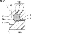
- 5G is a cross-sectional view schematically showing an example of the capillary structure of the vapor chamber according to the first embodiment of the present invention.
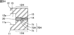
- FIG. 5H is a cross-sectional view schematically showing an example of the capillary structure of the vapor chamber according to the first embodiment of the present invention
- FIG. 5I is a cross-sectional view schematically showing an example of the capillary structure of the vapor chamber according to the first embodiment of the invention
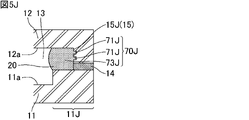
- FIG. 5J is a cross-sectional view schematically showing an example of the capillary structure of the vapor chamber according to the first embodiment of the invention.
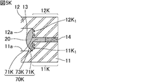
- FIG. 5K is a cross-sectional view schematically showing an example of the capillary structure of the vapor chamber according to the first embodiment of the present invention
- FIG. 5L is a cross-sectional view schematically showing an example of the capillary structure of the vapor chamber according to the first embodiment of the present invention;
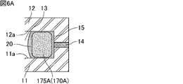
- FIG. 6A is a cross-sectional view schematically showing an example of the capillary structure of the vapor chamber according to the second embodiment of the invention.
- FIG. 6B is a cross-sectional view schematically showing an example of the capillary structure of the vapor chamber according to the second embodiment of the invention.
- FIG. 6C is a cross-sectional view schematically showing an example of the capillary structure of the vapor chamber according to the second embodiment of the invention.
- FIG. 7 is a cross-sectional view schematically showing an example of the capillary structure of the vapor chamber according to the third embodiment of the invention.
- FIG. 8 is a cross-sectional view schematically showing an example of the capillary structure of the vapor chamber according to the fourth embodiment of the invention.
- FIG. 6A is a cross-sectional view schematically showing an example of the capillary structure of the vapor chamber according to the second embodiment of the invention.
- FIG. 6B is a cross-sectional view schematically showing an example of the capillary
- FIG. 9A is a cross-sectional view schematically showing an example of the vapor chamber of the present invention having a different planar shape.
- FIG. 9B is a cross-sectional view schematically showing an example of the vapor chamber of the present invention having a different planar shape.
- FIG. 9C is a cross-sectional view schematically showing an example of the vapor chamber of the present invention having a different planar shape.
- FIG. 9D is a cross-sectional view schematically showing an example of the vapor chamber of the present invention having a different planar shape.
- FIG. 9E is a cross-sectional view schematically showing an example of the vapor chamber of the present invention having a different planar shape.
- the heat diffusion device of the present invention will be described below.
- the present invention is not limited to the following configurations, and can be appropriately modified and applied without changing the gist of the present invention. It should be noted that a combination of two or more of the individual preferred configurations of the invention described below is also the invention.
- a heat diffusion device of the present invention includes a housing having an internal space, a working medium enclosed in the internal space, and a wick arranged in the internal space, wherein the housings face each other in a thickness direction.
- the first inner wall surface and the second inner wall surface are joined to form a sealing portion that serves as a boundary of the inner space, and the wick comprises: Along the direction perpendicular to the thickness direction, there is a portion in contact with the first inner wall surface and the second inner wall surface of the housing, and a steam flow path is formed in the internal space of the housing.
- the sealing portion has a first side and a second side forming an interior angle of 180° or more, and a capillary structure is formed along the first side. ing.
- capillary structure means a structure that can transport a liquid-phase working medium by capillary force and does not divide the vapor flow path, and its shape is not particularly limited.
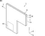
- FIG. 1 is a perspective view schematically showing an example of a vapor chamber, which is a heat diffusion device according to a first embodiment of the invention.
- the vapor chamber 1 shown in FIG. 1 includes a hollow housing 10 that is hermetically sealed.
- a heat source HS which is a heating element, is arranged on the outer wall surface of the housing 10 .
- the heat source HS include electronic components of electronic equipment, such as a central processing unit (CPU).
- the vapor chamber 1 is planar as a whole. That is, the housing 10 is planar as a whole.
- the “planar shape” includes a plate shape and a sheet shape, and the dimension in the width direction X (hereinafter referred to as width) and the dimension in the length direction Y (hereinafter referred to as length) are the thickness direction Z
- width width
- length dimension in the length direction
- Z It means a shape that is considerably large with respect to its dimensions (hereafter referred to as thickness or height). For example, it means a shape whose width and length are 10 times or more, preferably 100 times or more, the thickness.
- the size of the vapor chamber 1, that is, the size of the housing 10 is not particularly limited.
- the width and length of the vapor chamber 1 can be appropriately set according to the application.
- the width and length of the vapor chamber 1 are, for example, 5 mm or more and 500 mm or less, 20 mm or more and 300 mm or less, or 50 mm or more and 200 mm or less.
- the width and length of the vapor chamber 1 may be the same or different.
- the width and length of the vapor chamber are defined as maximum values in the width direction and the length direction.
- the housing 10 is preferably composed of a first sheet 11 and a second sheet 12 that face each other and whose outer edges are joined. Also, the first sheet 11 and the second sheet 12 are joined by brazing material 14 .
- Materials for the first sheet 11 and the second sheet 12 are not particularly limited as long as they have properties suitable for use as a vapor chamber, such as thermal conductivity, strength, softness, and flexibility.
- the material that constitutes the first sheet 11 and the second sheet 12 is preferably a metal, such as copper, nickel, aluminum, magnesium, titanium, iron, or an alloy containing them as a main component, and copper is particularly preferable. is.
- the materials forming the first sheet 11 and the second sheet 12 may be the same or different, but are preferably the same.
- the housing 10 is composed of the first sheet 11 and the second sheet 12
- the first sheet 11 and the second sheet 12 are joined together at their outer edges.
- Such joining method is joining using brazing material.
- the thicknesses of the first sheet 11 and the second sheet 12 are not particularly limited, but each is preferably 10 ⁇ m or more and 200 ⁇ m or less, more preferably 30 ⁇ m or more and 100 ⁇ m or less, still more preferably 40 ⁇ m or more and 60 ⁇ m or less.
- the thicknesses of the first sheet 11 and the second sheet 12 may be the same or different. Also, the thickness of each sheet of the first sheet 11 and the second sheet 12 may be the same over the entire area, or may be thin in part.
- first sheet 11 and the second sheet 12 are not particularly limited.
- first sheet 11 may have a flat plate shape with a constant thickness
- second sheet 12 may have a shape in which the outer edge portion is thicker than the portions other than the outer edge portion.
- the first sheet 11 may have a flat plate shape with a constant thickness
- the second sheet 12 may have a constant thickness and a portion other than the outer edge with respect to the outer edge may be convex outward. good.
- a recess is formed in the outer edge of the housing 10 . Therefore, the concave portion of the outer edge can be used when mounting the vapor chamber. Also, other components can be placed in the recesses of the outer edge.
- the thickness of the entire vapor chamber 1 is not particularly limited, it is preferably 50 ⁇ m or more and 500 ⁇ m or less.
- the planar shape of the housing 10 seen from the thickness direction Z shown in FIG. 1 is L-shaped.
- the planar shape of the housing is not particularly limited as long as the internal angle formed by the first side and the second side is 180° or more. shape), T-shape, stepped shape, and the like.
- the housing 10 may have a space (through-hole) inside the planar figure (that is, square shape).
- the planar shape of the housing 10 may be a shape according to the use of the vapor chamber, the shape of the location where the vapor chamber is installed, and other parts existing nearby.
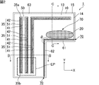
- FIG. 2 is a cross-sectional view of the vapor chamber shown in FIG. 1 taken along the line AA.
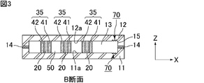
- 3 is a cross-sectional view taken along line BB of FIG. 2.
- housing 10 having interior space 13 includes working medium 20 enclosed in interior space 13 and wick 35 arranged in interior space 13 .
- the housing 10 has a first inner wall surface 11a and a second inner wall surface 12a facing each other in the thickness direction Z. They are joined to form a sealing portion 15 that bounds the internal space 13 .
- the wick 35 extends in a direction perpendicular to the thickness direction Z and has portions in contact with the first inner wall surface 11 a and the second inner wall surface 12 a of the housing 10 .
- the wick 35 includes a first porous body 41 and a second porous body 42 . These porous bodies have the function of transporting the working medium 20 by capillary force. Also, the first porous body 41 and the second porous body 42 that constitute the wick 35 have portions in contact with the first inner wall surface 11 a and the second inner wall surface 12 a of the housing 10 . By arranging these porous bodies in the internal space 13 of the housing 10, it is possible to absorb impacts from outside the housing 10 while ensuring the mechanical strength of the housing 10. FIG. The thickness of the first porous body 41 and the second porous body 42 forming the wick 35 is approximately the same as the thickness of the internal space 13 of the housing 10 . A vapor flow path 50 through which the vapor-phase working medium 20 flows is formed in the internal space 13 of the housing 10 .
- the direction in which the first porous body 41 and the second porous body 42 extend is between the first porous body 41 and the second porous body 42.
- a liquid pool flow path 51 is formed by further providing an interval along the width direction X).
- the liquid pool channel 51 can be used as a liquid channel through which the liquid-phase working medium 20 flows.
- the housing 10 is provided with an evaporation portion EP for evaporating the enclosed working medium 20 .
- a portion of the internal space 13 of the housing 10 that is in the vicinity of the heat source HS and is heated by the heat source HS corresponds to the evaporating portion EP.
- the working medium 20 is not particularly limited as long as it can cause a gas-liquid phase change in the environment inside the housing 10.
- water, alcohols, CFC alternatives, etc. can be used.
- the working medium is an aqueous compound, preferably water.
- the wick 35 extends from one end located in the evaporating part EP to the other end in plan view from the thickness direction Z. As shown in FIG. The other end is a portion away from the evaporator EP and serves as a condensing portion for condensing the evaporated working medium.
- the planar shape of the housing 10 is a so-called L shape.
- the sealing portion 15 has a first side 61 and a second side 62 forming an interior angle of 180° or more.
- the internal angle between the first side 61 and the second side 62 is the angle ⁇ in FIG. 2, which is 270° in this drawing.
- the first side 61 is a side located farther from the evaporating part EP than the second side 62 is.
- the wick 35 is not formed in the vicinity of the first side 61 and the second side 62, and from the shape of the housing 10, the direction in which the vapor chamber 1 is used (the direction with respect to the direction in which gravity is applied) Depending on the situation, liquid puddles may occur near the first side 61 and the second side 62 . Therefore, in the housing 10 , the capillary structure 70 is formed along the first side 61 and the second side 62 . Due to the existence of the capillary structure 70, the liquid puddles generated in the vicinity of the first side 61 and the second side 62 can be transported to the evaporating part EP. As a result, the amount of liquid transported can be improved, and the maximum heat transport amount can be improved.
- the capillary structure will be described in detail below.
- the capillary structure 70 is a liquid channel through which the liquid-phase working medium 20 flows, but is different from the wick 35 . Since the wick 35 is in contact with both the first inner wall surface 11a and the second inner wall surface 12a, it is configured to divide the steam flow path. On the other hand, the capillary structure 70 is configured so as not to divide the vapor flow path.
- FIG. 4A is a cross-sectional view taken along line CC of FIG. 2.
- FIG. FIG. 4B is an enlarged view of the dashed line portion of FIG. 4A. That is, FIG. 4B is a cross-sectional view of the vicinity of the sealing portion 15 that forms the first side 61 in the vapor chamber 1.
- FIGS. 4A and 4B in the housing 10 , the first inner wall surface 11 a and the second inner wall surface 12 a are joined with brazing material 14 to form a sealing portion 15 .
- brazing material conventionally known brazing materials can be used, and examples thereof include solder, copper, silver, copper alloys, phosphorous copper, and the like.
- a plurality of recesses 71 are formed in the first inner wall surface 11a and the second inner wall surface 12a in the vicinity of the sealing portion 15, which constitute a capillary structure 70.
- the concave portion 71 forming the capillary structure 70 may have any shape as long as it can transport the liquid-phase working medium 20 by capillary force.
- the recess 71 shown in FIG. 4B is formed by a bottom surface and two walls perpendicular to the bottom surface. It may be V-shaped, or it may be U-shaped.
- the concave portions 71 may be formed by etching or the like after the first sheet 11 and the second sheet 12 are formed.
- the width of the concave portion 71 is not particularly limited as long as the liquid-phase working medium can be transported by capillary force, but is preferably 2 ⁇ m or more and 200 ⁇ m or less. Moreover, the depth of the concave portion 71 is preferably 2 ⁇ m or more and 200 ⁇ m or less.
- the capillary structure 70 is formed on both the first inner wall surface 11a and the second inner wall surface 12a. It is sufficient that a capillary structure is formed on one side.
- a capillary structure 70 is formed along the first side 61 and the second side 62 in the vapor chamber 1 . Therefore, even if a liquid pool occurs in the vicinity of the first side 61 or the second side 62, the capillary structure 70 can transport the liquid-phase working medium 20 to the evaporating part EP. That is, it is possible to solve the problem that the maximum amount of heat transport is reduced due to the influence of the liquid pool generated at the position where the wick 35 is not formed.
- the wick 35 has a first end 35a and a second end 35b. It faces the sealing portion 15 forming the third side 63 other than the second side 62 , and the capillary structure 70 is not formed along the third side 63 .
- the wick 35 can transport the working medium 20 to the evaporating section EP. That is, in the vapor chamber 1 , the working medium 20 can be transported even if the capillary structure 70 is not formed along the third side 63 .
- the capillary structure may not be formed along all sides formed by the sealing portion. If the capillary structure is formed along the entire side formed by the sealing portion, the vapor-phase working medium 20 is less likely to move to the capillary structure 70 portion, and the maximum heat transfer rate tends to decrease. However, if there is a portion where the capillary structure is not formed, the vapor-phase working medium tends to move to the portion where the capillary structure is not formed, so that the maximum heat transfer rate is less likely to decrease. Also, by not forming a capillary structure, the manufacturing cost of the vapor chamber can be reduced.
- a capillary structure may be formed along all sides formed by the sealing portion.
- 5A to 5L are cross-sectional views schematically showing an example of the capillary structure of the vapor chamber according to the first embodiment of the invention.
- a capillary structure 70A is formed by recesses 71A.
- the recess 71A may be formed by applying the brazing material 14A between the first inner wall surface 11a and the second inner wall surface 12a with a dispenser so that the exposed surface of the brazing material 14A is uneven. After bonding the first inner wall surface 11a and the second inner wall surface 12a, the exposed surface of the brazing material 14A may be corroded by etching or the like.
- the structure of the capillary structure 70B and its vicinity shown in FIG. 5B has no recesses formed in the first inner wall surface 11a and the second inner wall surface 12a, and the vicinity of the surface of the brazing material 14B exposed in the internal space 13 is porous. It is the same as the structure in the vicinity of the capillary structure 70 except that it is 72B.
- a capillary structure 70B is formed by a porous body 72B.
- the porous body 72B is formed by arranging a member that becomes porous by heating in the vicinity of the exposed surface of the brazing material 14B when arranging the brazing material 14B on the first inner wall surface 11a and the second inner wall surface 12a. can be formed by performing
- a member that becomes porous by heating is, for example, metal powder, ceramic powder, or the like.
- these members are included in the brazing material 14B, these members are sintered during brazing to form a metal porous sintered body and a ceramic porous sintered body.
- the capillary structure 70C shown in FIG. 5C and its vicinity recesses are not formed in the first inner wall surface 11a and the second inner wall surface 12a, and an internal space is formed between the first inner wall surface 11a and the second inner wall surface 12a.
- the structure is the same as the structure in the vicinity of the capillary structure 70 except that the porous body 72C exposed at 13 and the brazing material 14C are arranged inside thereof.
- a porous body 72C forms a capillary structure 70C.
- the porous body 72C is formed by arranging and brazing the brazing material 14C so that a gap connecting to the internal space 13 is formed between the first inner wall surface 11a and the second inner wall surface 12a, and then heating the gap to form a porous body. It can be formed by arranging and heating the members to be.
- Examples of such a porous body 72C include a metal porous sintered body, a ceramic porous sintered body, and the like.
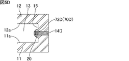
- the structure of the capillary structure 70D and its vicinity shown in FIG. 5D does not have recesses formed in the first inner wall surface 11a and the second inner wall surface 12a, and the porous body 72D is formed in the inner space 13 so as to be in contact with the brazing material 14D. It is the same as the structure in the vicinity of the capillary structure 70 except that it is formed.
- a porous body 72D forms a capillary structure 70D.
- the porous body 72D is formed by brazing the first inner wall surface 11a and the second inner wall surface 12a with the brazing filler metal 14D, and then placing a member that becomes a porous body by heating on the brazing filler metal 14D and heating it. can be done.
- Examples of such a porous body 72D include a metal porous sintered body, a ceramic porous sintered body, and the like.
- the capillary structure 70E shown in FIG. 5E and the structure in the vicinity thereof recesses are not formed in the first inner wall surface 11a and the second inner wall surface 12a, and the first sheet 11 near the sealing portion 15 covers the thick wall region 11E.
- the structure in the vicinity of the capillary structure 70 is the same except that a narrow space 73E is formed between the first inner wall surface 11a and the second inner wall surface 12a located in the thick wall region 11E.
- narrow spaces 73E form capillary structures 70E.
- the narrow space 73E can be formed by preparing in advance the first sheet 11 having the thick wall region 11E.
- the width of the narrow space 73E (the distance from the first inner wall surface 11a to the second inner wall surface 12a) is not particularly limited as long as the liquid-phase working medium can be transported by capillary force, but is preferably 2 ⁇ m or more and 200 ⁇ m or less. Also, the depth of the narrow space 73E is preferably 2 ⁇ m or more and 200 ⁇ m or less.
- the capillary structure 70F and its vicinity shown in FIG. 5F recesses are not formed in the first inner wall surface 11a and the second inner wall surface 12a, and the first sheet 11 near the sealing portion 15 covers the thick wall region 11F.
- the second sheet 12 near the sealing portion 15 has a thick-wall region 12F, and is between the first inner wall surface 11a located in the thick-wall region 11F and the second inner wall surface 12a located in the thick-wall region 12F.
- the structure is the same as the structure in the vicinity of the capillary structure 70 except that a narrow space 73F is formed at the end.
- narrow spaces 73F form capillary structures 70F.
- the narrow space 73F can be formed by preparing in advance the first sheet 11 having the thick wall region 11F and the second sheet having the thick wall region 12F.
- the first sheet 11 in the vicinity of the sealing portion 15 has the thick wall region 11G, and the first inner wall surface 11a and the second inner wall surface 11a located in the thick wall region 11G. It has the same structure as the capillary structure 70 and its neighboring structure except that a narrow space 73G is formed between the capillary structure 70 and the structure 12a.
- narrow spaces 73G and recesses 71 form capillary structures 70G.
- the method of forming the narrow space 73G is the same as the method of forming the narrow space 73E. Since the method of forming the recess 71 has already been explained, the explanation is omitted here.
- the capillary structure 70H shown in FIG. 5H and the structure in the vicinity thereof the first sheet 11 near the sealing portion 15 has the thick-wall region 11H, and the second sheet 12 near the sealing portion 15 has the thick-wall region 12H.
- a narrow space 73H is formed between the first inner wall surface 11a located in the thick-wall region 11H and the second inner wall surface 12a located in the thick-wall region 12H
- the capillary structure 70 and its vicinity are Same as structure.
- narrow spaces 73H and recesses 71 form capillary structures 70H.
- the method of forming the narrow space 73H is the same as the method of forming the narrow space 73F. Since the method of forming the recess 71 has already been explained, the explanation is omitted here.
- recesses 71I form capillary structures 70I.
- the method for forming the recess 71I is the same as the method for forming the recess 71 described above.
- the capillary structure 70J shown in FIG. 5J and the structure in the vicinity thereof recesses are not formed in the first inner wall surface 11a and the second inner wall surface 12a, and the first sheet 11 in the vicinity of the sealing portion 15 covers the thick wall region 11J.
- a narrow space 73J is formed between the first inner wall surface 11a and the second inner wall surface 12a located in the thick wall region 11J, and the recess 71J is formed in the side surface 15J of the sealing portion 15 of the second sheet 12. It is the same as the structure in the vicinity of the capillary structure 70 except that it is formed.
- narrow spaces 73J and recesses 71J form capillary structures 70J.
- the method of forming the narrow space 73J is the same as the method of forming the narrow space 73E.
- the method for forming the recess 71J is the same as the method for forming the recess 71 described above.
- the first sheet 11 near the sealing portion 15 covers the thick wall region 11K.
- the second sheet 12 near the sealing portion 15 has a thick-wall region 12K, and is between the first inner wall surface 11a located in the thick-wall region 11K and the second inner wall surface 12a located in the thick-wall region 12K.
- a narrow space 73K is formed in the capillaries 11K and 12K1 of the thick-wall region 11K of the first sheet 11 and the side surface 12K-1 of the thick-wall region 12K of the second sheet 12, respectively. It is the same as the structure near the structure 70 .
- narrow spaces 73K and recesses 71K form capillary structures 70K.
- the method of forming the narrow space 73K is the same as the method of forming the narrow space 73F.
- the method for forming the recess 71K is the same as the method for forming the recess 71 described above.
- the structure of the capillary structure 70L and the vicinity thereof shown in FIG. 5L has no recesses on the first inner wall surface 11a and the second inner wall surface 12a, and has protrusions 74L. It is the same as the neighboring structure.
- the capillary structure 70L is formed by the projections 74L.
- the convex portion 74L can be formed by providing a convex shape in advance when the first sheet 11 and the second sheet 12 are manufactured.
- the convex portion 74L is formed by an upper surface and two walls perpendicular to the upper surface.
- the shape may be an inverted V shape, or an inverted U shape.
- the interval between the convex portions 74L is not particularly limited as long as the liquid-phase working medium can be transported by capillary force, but is preferably 2 ⁇ m or more and 200 ⁇ m or less. Also, the height of the convex portion 74L is preferably 2 ⁇ m or more and 200 ⁇ m or less.
- a vapor chamber which is a heat diffusion device according to a second embodiment of the present invention
- the vapor chamber according to the second embodiment of the invention is the same as the vapor chamber according to the first embodiment of the invention, except that a fiber bundle having capillary force is used as the capillary structure.
- a capillary structure of a vapor chamber according to a second embodiment of the present invention will be described below with reference to the drawings. 6A to 6C are cross-sectional views schematically showing an example of the capillary structure of the vapor chamber according to the second embodiment of the invention.
- a fiber bundle 175A forms a capillary structure 170A.
- the fiber bundle is not particularly limited, but a braided fiber bundle can be used.
- the fibers for example, metal wires such as copper, aluminum, and stainless steel wires, and non-metal wires such as carbon fibers and glass fibers can be used.
- a metal wire is preferable because of its high thermal conductivity.
- a fiber bundle can be obtained by bundling about 200 copper wires with a diameter of about 0.03 mm.
- capillary structure 170B and its vicinity shown in FIG. 6B is the same as the structure of the capillary structure 70E and its vicinity except that the fiber bundle 175B is formed in the vicinity of the sealing portion 15.
- FIG. 6B capillary structure 170A is formed by narrow space 73E and fiber bundle 175B.
- the structure of the capillary structure 170C and its vicinity shown in FIG. 6C is the same as the structure of the capillary structure 70F and its vicinity except that the fiber bundle 175C is formed in the vicinity of the sealing portion 15.
- FIG. 6C narrow spaces 73F and fiber bundles 175C form capillary structures 170C.
- FIG. 7 is a cross-sectional view schematically showing an example of a capillary structure according to a third embodiment of the vapor chamber of the invention.
- the method of joining the first inner wall surface 11a and the second inner wall surface 12a is not particularly limited, but for example, laser welding, resistance welding, diffusion bonding, TIG welding (tungsten-inert gas welding), or ultrasonic bonding is used. be able to.
- FIG. 8 is a cross-sectional view schematically showing an example of a capillary structure according to a fourth embodiment of the vapor chamber of the invention.
- the capillary structure 370 shown in FIG. 8 and the structure in the vicinity thereof does not use brazing material, and the first inner wall surface 11a and the second inner wall surface 12a are directly joined to each other. It has the same configuration as
- FIGS. 9A to 9E are cross-sectional views schematically showing examples of vapor chambers of the present invention having different planar shapes.
- the vapor chamber 401 shown in FIG. 9A has an L-shaped planar shape. Also, in vapor chamber 401, wick 435 is formed in an L shape. In the vapor chamber 401 , the internal angle formed by the first side 461 and the second side 462 is rounded, and the capillary structure 470 is formed along the first side 461 and the second side 462 . When the interior angle formed by the first side 461 and the second side 462 is R-chamfered, the angle of the interior angle between the first side 461 and the second side 462 is the extension of the straight portion of the first side 461, It means an internal angle formed by an extension line of the straight portion of the second side 462 .
- the vapor chamber 501 shown in FIG. 9B has a C-shaped (U-shaped) planar shape. Also, in the vapor chamber 501, the wick 535 is formed in a C shape (U shape). As shown in FIG. 9B, in the vapor chamber 501, the upper side and the lower side forming the inside of the C shape (U-shape) are the first side 561 and the first side 561', and the side connecting the upper side and the lower side. is the second side 562 . The internal angle between the first side 561 and the second side 562 is 270°, and the internal angle between the second side 562 and the first side 561′ is 270°. Also, in the vapor chamber 501, capillary structures 570 are formed along the first side 561, the second side 562 and the first side 561'.
- liquid pools may occur at multiple locations.
- the vapor chamber 601 shown in FIG. 9C has a T-shaped planar shape. Also, in the vapor chamber 601, the wick 635 is formed in a T shape. As shown in FIG. 9C, the vapor chamber 601 has a first side and a second side on the right and left sides of the T shape, respectively. is 270°, and the interior angle formed by the left first side 661' and the second side 662' is 270°. Also, in the vapor chamber 601, capillary structures 670 are formed along the first side 661, the second side 662, the first side 661' and the second side 662'.
- liquid pools may occur at multiple locations, so providing a capillary structure at each location can improve the maximum heat transfer amount.
- the vapor chamber 701 shown in FIG. 9D has a crank-shaped planar shape. Also, in vapor chamber 701, wick 735 is formed in a crank shape. As shown in FIG. 9D, in the vapor chamber 701, the internal angle between the first side 761 and the second side 762 is 270°, and the internal angle between the first side 761′ and the second side 762′ is 270°. is 270°. Also, in the vapor chamber 701, capillary structures 770 are formed along the first side 761, the second side 762, the first side 761' and the second side 762'.
- liquid pools may occur at multiple locations, so providing a capillary structure at each location can improve the maximum heat transfer amount.
- the vapor chamber 801 shown in FIG. 9E has a square shape in plan view. That is, the planar shape of the vapor chamber 801 is a shape having a square cavity in the center. Also, in the vapor chamber 801, the wick 835 is formed in an L shape and a left-right reversed shape of the L shape. As shown in FIG. 9E, in the vapor chamber 801, the upper and lower sides forming the cavity are the first side 861 and the first side 861', respectively, and the left and right sides are the second side 862 and the second side 862'. be.
- the interior angle between the first side 861 and the second side 862 is 270°
- the interior angle between the first side 861′ and the second side 862′ is 270°
- the first side 861′ and The interior angle formed by the second side 862 is 270°
- the interior angle formed by the first side 861 and the second side 862' is 270°.
- capillary structures 870 are formed along the first side 861, the second side 862, the first side 861' and the second side 862'.
- liquid pools may occur in multiple locations, so providing a capillary structure at each location can improve the maximum heat transfer amount.
- capillary structures are formed along both the first side and the second side.
- the capillary structure may be formed only along the first side as long as the liquid-phase working medium can be transported from the liquid reservoir.
- the vapor chamber of the present invention can be mounted on electronic equipment for the purpose of heat dissipation. Therefore, it can be used as an electronic device comprising the vapor chamber of the present invention and an electronic component attached to the outer wall surface of a housing that constitutes the vapor chamber.
- the vapor chamber of the present invention operates independently without the need for external power, and utilizes the latent heat of vaporization and latent heat of condensation of the working medium to diffuse heat two-dimensionally at high speed. Therefore, the electronic device including the vapor chamber of the present invention can effectively dissipate heat in a limited space inside the electronic device.
- the electronic component corresponds to the heat source HS shown in FIG.
- Examples of electronic devices include smartphones, tablet terminals, laptops, game machines, and wearable devices.
- Electronic parts that are objects to be cooled include, for example, heat generating elements such as central processing units (CPUs), light emitting diodes (LEDs), and power semiconductors.
- the electronic components may be attached directly to the outer wall surface of the housing, or may be attached via other members such as adhesives, sheets, and tapes with high thermal conductivity.
- the vapor chamber of the present invention can be used for a wide range of applications in fields such as personal digital assistants. For example, it can be used to lower the temperature of a heat source such as a CPU and extend the operating time of electronic equipment, and can be used in smartphones, tablet terminals, laptop computers, and the like.
- Reference Signs List 1 401, 501, 601, 701, 801 vapor chamber 10 housing 11 first sheet 11a first inner wall surface 11E, 11F, 11G, 11H, 11J, 11K thick wall region 12 second sheet 12a second inner wall surface 12F, 12H, 12K thick wall region 13 internal space 14, 14A, 14B, 14C, 14D brazing material 15 sealing portion 11K 1 , 12K 1 , 15I, 15J side surface of sealing portion 20 working medium 35 wick 35a first end 35b second second end 41 first porous body 42 second porous body 50 steam channel 51 liquid pool channel 61, 461, 561, 561', 661, 661', 761, 761', 861, 861' first side 62, 462, 562, 662, 662', 762, 762', 862, 862' Second side 63 Third side 70, 70A, 70B, 70C, 70D, 70E, 70F, 70G, 70H, 70I, 70J, 70K, 70L, 170A , 1
Landscapes
- Engineering & Computer Science (AREA)
- Physics & Mathematics (AREA)
- General Engineering & Computer Science (AREA)
- Thermal Sciences (AREA)
- Sustainable Development (AREA)
- Mechanical Engineering (AREA)
- Life Sciences & Earth Sciences (AREA)
- Condensed Matter Physics & Semiconductors (AREA)
- General Physics & Mathematics (AREA)
- Computer Hardware Design (AREA)
- Microelectronics & Electronic Packaging (AREA)
- Power Engineering (AREA)
- Cooling Or The Like Of Semiconductors Or Solid State Devices (AREA)
Abstract
The present invention provides a vapor chamber which makes it possible to increase the proportion of a vapor flow passage, thereby increasing the maximum heat transportation amount and also increasing a uniform heating property. A heat diffusion device (1) according to the present invention comprises: a housing (10) that has an internal space (13); an operation medium (20) that is sealed in the internal space (13); and a wick (35) that is disposed in the internal space (13), wherein the housing (10) has a first inner wall surface (11a) and a second inner wall surface (12a) which are opposite from each other in the thickness direction (Z), the first inner wall surface (11a) and the second inner wall surface (12a) are joined so as to form a sealing part (15) which serves as the boundary of the internal space (13), the wick (35) extends in a direction perpendicular to the thickness direction (Z) and has a part which is in contact with the first inner wall surface (11a) and the second inner wall surface (12a) of the housing (10), a vapor flow passage (50) is formed in the internal space (13) of the housing (10), and in a view of the housing (10) from the thickness direction (Z), the sealing part (15) has a first side (61) and a second side (62) which form an interior angle of 180° or more, and a capillary structure (70) is formed along the first side (61).
Description
本発明は、熱拡散デバイスに関する。
The present invention relates to heat diffusion devices.
近年、素子の高集積化及び高性能化による発熱量が増加している。また、製品の小型化が進むことで、発熱密度が増加するため、放熱対策が重要となっている。この状況はスマートフォン及びタブレットなどのモバイル端末の分野において特に顕著である。熱対策部材としては、グラファイトシートなどが用いられることが多いが、その熱輸送量は十分ではないため、様々な熱対策部材の使用が検討されている。中でも、非常に効果的に熱を拡散させることが可能であるとして、面状のヒートパイプであるベーパーチャンバー(熱拡散デバイス)の使用の検討が進んでいる。
In recent years, the amount of heat generated has increased due to the high integration and high performance of devices. In addition, as products become smaller, heat generation density increases, so heat dissipation measures have become important. This situation is particularly pronounced in the field of mobile terminals such as smartphones and tablets. A graphite sheet or the like is often used as a heat countermeasure member, but its heat transfer capacity is not sufficient, so the use of various heat countermeasure members has been investigated. Among them, the use of a vapor chamber (heat diffusion device), which is a planar heat pipe, is being studied because it is possible to diffuse heat very effectively.
ベーパーチャンバーは、筐体の内部に、作動媒体と、毛細管力によって作動媒体を輸送するウィックとが封入された構造を有する。上記作動媒体は、発熱素子からの熱を吸収する蒸発部において発熱素子からの熱を吸収してベーパーチャンバー内で蒸発した後、凝縮部に移動し、冷却されて液相に戻る。液相に戻った作動媒体は、ウィックの毛細管力によって再び発熱素子側の蒸発部に移動し、発熱素子を冷却する。これを繰り返すことにより、ベーパーチャンバーは外部動力を有することなく自立的に作動し、作動媒体の蒸発潜熱及び凝縮潜熱を利用して、二次元的に高速で熱を拡散することができる。
The vapor chamber has a structure in which a working medium and a wick that transports the working medium by capillary force are sealed inside the housing. The working medium absorbs heat from the heating element in the evaporating section that absorbs heat from the heating element, evaporates in the vapor chamber, moves to the condensing section, is cooled, and returns to the liquid phase. The working medium that has returned to the liquid phase moves again to the evaporating portion on the heating element side by the capillary force of the wick, and cools the heating element. By repeating this, the vapor chamber can operate independently without external power, and heat can be two-dimensionally diffused at high speed by utilizing the latent heat of vaporization and latent heat of condensation of the working medium.
特許文献1には、第1金属シート又は第2金属シートの周縁の全周にわたって、作動液が通る周縁液流路部が形成されたベーパーチャンバーが開示されている。
Patent Literature 1 discloses a vapor chamber in which a peripheral fluid passage portion through which the working fluid flows is formed over the entire peripheral edge of the first metal sheet or the second metal sheet.
特許文献1に記載されたベーパーチャンバーでは、液状の作動液が通る液流路部(ウィック)が、ベーパーチャンバーを平面視した形状において全面に形成されている(特許文献1の図4参照)。
また、ベーパーチャンバーを平面視した形状が長方形であり、熱源が長方形の中心に位置することを前提にしたウィックの形状が示されている(特許文献1の各図参照)。 In the vapor chamber described inPatent Document 1, a liquid flow path portion (wick) through which the liquid working fluid passes is formed on the entire surface of the vapor chamber when viewed from above (see FIG. 4 of Patent Document 1).
Further, the shape of the wick is shown on the premise that the shape of the vapor chamber when viewed from above is rectangular, and the heat source is positioned at the center of the rectangle (see each figure of Patent Document 1).
また、ベーパーチャンバーを平面視した形状が長方形であり、熱源が長方形の中心に位置することを前提にしたウィックの形状が示されている(特許文献1の各図参照)。 In the vapor chamber described in
Further, the shape of the wick is shown on the premise that the shape of the vapor chamber when viewed from above is rectangular, and the heat source is positioned at the center of the rectangle (see each figure of Patent Document 1).
ベーパーチャンバーを平面視した形状において、ウィックが全面に形成されていると、作動液の蒸気が通る蒸気流路の割合が相対的に低下してしまう。蒸気が通る部分の割合が低いと最大熱輸送量が低下するという問題が生じる。
また、蒸気流路がウィックにより分断されるので均熱性が低下するという問題が生じる。さらに、ウィックを全面に形成すると、ウィックの形成に係るコストが増大するという問題も生じる。 If the wick is formed on the entire surface of the vapor chamber when viewed from above, the proportion of the vapor flow path through which the vapor of the working fluid passes is relatively reduced. A problem arises that the maximum heat transfer rate decreases when the percentage of the portion through which the steam passes is low.
In addition, since the steam flow path is divided by the wick, there arises a problem that uniformity of heat is lowered. Furthermore, forming the wick on the entire surface also raises the problem that the cost associated with the formation of the wick increases.
そこで、ウィックを全面に形成するのではなく、必要と思われる部分だけにウィックを形成することが検討されている。
ウィックを全面に形成しない場合であり、かつ、ベーパーチャンバーを平面視した形状が長方形ではなく、180°以上の内角を形成する第1辺と第2辺を有する形状(以下、異形形状ともいう)の場合を考える。この場合、ベーパーチャンバーが使用される際の向き(重力の加わる方向に対する向き)によっては、液溜まりが上記第1辺又は第2辺の近傍に生じてしまう。第1辺又は第2辺の近傍に生じた液溜まりはウィックにより回収できないので、液体の輸送量が少なくなり、最大熱輸送量が低下するという問題が生じる。 Therefore, instead of forming the wick over the entire surface, it is being considered to form the wick only where it is considered necessary.
This is the case where the wick is not formed on the entire surface, and the shape of the vapor chamber when viewed from above is not a rectangle, but a shape having first and second sides forming an interior angle of 180° or more (hereinafter also referred to as a deformed shape). Consider the case of In this case, depending on the direction in which the vapor chamber is used (orientation relative to the direction in which gravity is applied), a liquid pool may occur near the first side or the second side. Liquid pools formed near the first side or the second side cannot be collected by the wick, so the amount of liquid transported is reduced, resulting in a problem of a decrease in the maximum heat transport amount.
本発明は、上記の問題を解決するためになされたものであり、蒸気流路の割合を高くして、最大熱輸送量を高くし、均熱性も高くすることのできる熱拡散デバイスを提供することを目的とする。
The present invention has been made to solve the above problems, and provides a heat diffusion device that can increase the maximum heat transfer rate and heat uniformity by increasing the ratio of steam flow paths. The purpose is to
本発明の熱拡散デバイスは、内部空間を有する筐体と、前記内部空間に封入された作動媒体と、前記内部空間に配置されたウィックと、を備え、前記筐体は、厚さ方向に対向する第1内壁面及び第2内壁面を有し、前記第1内壁面及び前記第2内壁面は接合されて、前記内部空間の境界となる封止部を形成しており、前記ウィックは、前記厚さ方向に垂直な方向に沿い、前記筐体の前記第1内壁面及び前記第2内壁面に接する部分を有し、前記筐体の内部空間には、蒸気流路が形成されており、前記厚さ方向から前記筐体を見た際、前記封止部は180°以上の内角を形成する第1辺と第2辺を有し、前記第1辺に沿ってキャピラリーストラクチャーが形成されている。
A heat diffusion device of the present invention includes a housing having an internal space, a working medium enclosed in the internal space, and a wick arranged in the internal space, wherein the housings face each other in a thickness direction. The first inner wall surface and the second inner wall surface are joined to form a sealing portion that serves as a boundary of the inner space, and the wick comprises: Along the direction perpendicular to the thickness direction, there is a portion in contact with the first inner wall surface and the second inner wall surface of the housing, and a steam flow path is formed in the internal space of the housing. , when the housing is viewed from the thickness direction, the sealing portion has a first side and a second side forming an interior angle of 180° or more, and a capillary structure is formed along the first side. ing.
本発明によれば、蒸気流路の割合を高くして、最大熱輸送量を高くし、均熱性も高くすることのできる熱拡散デバイスを提供することができる。
According to the present invention, it is possible to provide a heat diffusion device that can increase the proportion of the steam flow path, increase the maximum heat transfer amount, and improve the heat uniformity.
以下、本発明の熱拡散デバイスについて説明する。
しかしながら、本発明は、以下の構成に限定されるものではなく、本発明の要旨を変更しない範囲において適宜変更して適用することができる。なお、以下において記載する本発明の個々の望ましい構成を2つ以上組み合わせたものもまた本発明である。 The heat diffusion device of the present invention will be described below.
However, the present invention is not limited to the following configurations, and can be appropriately modified and applied without changing the gist of the present invention. It should be noted that a combination of two or more of the individual preferred configurations of the invention described below is also the invention.
本発明の熱拡散デバイスは、内部空間を有する筐体と、前記内部空間に封入された作動媒体と、前記内部空間に配置されたウィックと、を備え、前記筐体は、厚さ方向に対向する第1内壁面及び第2内壁面を有し、前記第1内壁面及び前記第2内壁面は接合されて、前記内部空間の境界となる封止部を形成しており、前記ウィックは、前記厚さ方向に垂直な方向に沿い、前記筐体の前記第1内壁面及び前記第2内壁面に接する部分を有し、前記筐体の内部空間には、蒸気流路が形成されており、前記厚さ方向から前記筐体を見た際、前記封止部は180°以上の内角を形成する第1辺と第2辺を有し、前記第1辺に沿ってキャピラリーストラクチャーが形成されている。
A heat diffusion device of the present invention includes a housing having an internal space, a working medium enclosed in the internal space, and a wick arranged in the internal space, wherein the housings face each other in a thickness direction. The first inner wall surface and the second inner wall surface are joined to form a sealing portion that serves as a boundary of the inner space, and the wick comprises: Along the direction perpendicular to the thickness direction, there is a portion in contact with the first inner wall surface and the second inner wall surface of the housing, and a steam flow path is formed in the internal space of the housing. , when the housing is viewed from the thickness direction, the sealing portion has a first side and a second side forming an interior angle of 180° or more, and a capillary structure is formed along the first side. ing.
なお、本明細書において「キャピラリーストラクチャー」とは、毛細管力により液相の作動媒体を輸送でき、蒸気流路を分断しない構造のことを意味し、その形状は特に限定されない。
In this specification, the term "capillary structure" means a structure that can transport a liquid-phase working medium by capillary force and does not divide the vapor flow path, and its shape is not particularly limited.
以下に、本発明の熱拡散デバイスの具体的な実施形態を示す。
以下に示す各実施形態は例示であり、異なる実施形態で示した構成の部分的な置換又は組み合わせが可能であることは言うまでもない。第2実施形態以降では、第1実施形態と共通の事項についての記述は省略し、異なる点についてのみ説明する。特に、同様の構成による同様の作用効果については、実施形態毎には逐次言及しない。 Specific embodiments of the heat spreading device of the present invention are shown below.
Each embodiment shown below is an example, and it goes without saying that partial replacement or combination of configurations shown in different embodiments is possible. In the second and subsequent embodiments, descriptions of matters common to the first embodiment will be omitted, and only different points will be described. In particular, similar actions and effects due to similar configurations will not be mentioned sequentially for each embodiment.
以下に示す図面は模式的なものであり、その寸法や縦横比の縮尺などは実際の製品とは異なる場合がある。
The drawings shown below are schematic, and their dimensions and aspect ratio may differ from the actual product.
[第1実施形態]
図1は、本発明の第1実施形態に係る熱拡散デバイスであるベーパーチャンバーの一例を模式的に示す斜視図である。 [First embodiment]
FIG. 1 is a perspective view schematically showing an example of a vapor chamber, which is a heat diffusion device according to a first embodiment of the invention.
図1は、本発明の第1実施形態に係る熱拡散デバイスであるベーパーチャンバーの一例を模式的に示す斜視図である。 [First embodiment]
FIG. 1 is a perspective view schematically showing an example of a vapor chamber, which is a heat diffusion device according to a first embodiment of the invention.
図1に示すベーパーチャンバー1は、気密状態に密閉された中空の筐体10を備える。図1に示すように、筐体10の外壁面には、発熱素子である熱源(heat source)HSが配置される。熱源HSとしては、電子機器の電子部品、例えば中央処理装置(CPU)等が挙げられる。
The vapor chamber 1 shown in FIG. 1 includes a hollow housing 10 that is hermetically sealed. As shown in FIG. 1, a heat source HS, which is a heating element, is arranged on the outer wall surface of the housing 10 . Examples of the heat source HS include electronic components of electronic equipment, such as a central processing unit (CPU).
ベーパーチャンバー1は、全体として面状である。すなわち、筐体10は、全体として面状である。ここで、「面状」とは、板状及びシート状を包含し、幅方向Xの寸法(以下、幅という)及び長さ方向Yの寸法(以下、長さという)が厚さ方向Zの寸法(以下、厚さ又は高さという)に対して相当に大きい形状を意味する。例えば、幅及び長さが、厚さの10倍以上、好ましくは100倍以上である形状を意味する。
The vapor chamber 1 is planar as a whole. That is, the housing 10 is planar as a whole. Here, the “planar shape” includes a plate shape and a sheet shape, and the dimension in the width direction X (hereinafter referred to as width) and the dimension in the length direction Y (hereinafter referred to as length) are the thickness direction Z It means a shape that is considerably large with respect to its dimensions (hereafter referred to as thickness or height). For example, it means a shape whose width and length are 10 times or more, preferably 100 times or more, the thickness.
ベーパーチャンバー1の大きさ、すなわち、筐体10の大きさは、特に限定されない。ベーパーチャンバー1の幅及び長さは、用途に応じて適宜設定することができる。ベーパーチャンバー1の幅及び長さは、各々、例えば、5mm以上500mm以下、20mm以上300mm以下又は50mm以上200mm以下である。ベーパーチャンバー1の幅及び長さは、同じであってもよく、異なっていてもよい。
ベーパーチャンバーが異形形状であるとき、ベーパーチャンバーの幅及び長さは、幅方向及び長さ方向における最大値として定める。 The size of thevapor chamber 1, that is, the size of the housing 10 is not particularly limited. The width and length of the vapor chamber 1 can be appropriately set according to the application. The width and length of the vapor chamber 1 are, for example, 5 mm or more and 500 mm or less, 20 mm or more and 300 mm or less, or 50 mm or more and 200 mm or less. The width and length of the vapor chamber 1 may be the same or different.
When the vapor chamber has an irregular shape, the width and length of the vapor chamber are defined as maximum values in the width direction and the length direction.
ベーパーチャンバーが異形形状であるとき、ベーパーチャンバーの幅及び長さは、幅方向及び長さ方向における最大値として定める。 The size of the
When the vapor chamber has an irregular shape, the width and length of the vapor chamber are defined as maximum values in the width direction and the length direction.
筐体10は、外縁部が接合された対向する第1シート11及び第2シート12から構成されることが好ましい。また、第1シート11及び第2シート12はロウ材14により接合されている。第1シート11及び第2シート12を構成する材料は、ベーパーチャンバーとして用いるのに適した特性、例えば熱伝導性、強度、柔軟性、可撓性等を有するものであれば、特に限定されない。第1シート11及び第2シート12を構成する材料は、好ましくは金属であり、例えば銅、ニッケル、アルミニウム、マグネシウム、チタン、鉄、又はそれらを主成分とする合金等であり、特に好ましくは銅である。第1シート11及び第2シート12を構成する材料は、同じであってもよく、異なっていてもよいが、好ましくは同じである。
The housing 10 is preferably composed of a first sheet 11 and a second sheet 12 that face each other and whose outer edges are joined. Also, the first sheet 11 and the second sheet 12 are joined by brazing material 14 . Materials for the first sheet 11 and the second sheet 12 are not particularly limited as long as they have properties suitable for use as a vapor chamber, such as thermal conductivity, strength, softness, and flexibility. The material that constitutes the first sheet 11 and the second sheet 12 is preferably a metal, such as copper, nickel, aluminum, magnesium, titanium, iron, or an alloy containing them as a main component, and copper is particularly preferable. is. The materials forming the first sheet 11 and the second sheet 12 may be the same or different, but are preferably the same.
筐体10が第1シート11及び第2シート12から構成される場合、第1シート11及び第2シート12は、これらの外縁部において互いに接合される。かかる接合の方法は、ロウ材を用いた接合である。
When the housing 10 is composed of the first sheet 11 and the second sheet 12, the first sheet 11 and the second sheet 12 are joined together at their outer edges. Such joining method is joining using brazing material.
第1シート11及び第2シート12の厚さは、特に限定されないが、各々、好ましくは10μm以上200μm以下、より好ましくは30μm以上100μm以下、さらに好ましくは40μm以上60μm以下である。第1シート11及び第2シート12の厚さは、同じであってもよく、異なっていてもよい。また、第1シート11及び第2シート12の各シートの厚さは、全体にわたって同じであってもよく、一部が薄くてもよい。
The thicknesses of the first sheet 11 and the second sheet 12 are not particularly limited, but each is preferably 10 μm or more and 200 μm or less, more preferably 30 μm or more and 100 μm or less, still more preferably 40 μm or more and 60 μm or less. The thicknesses of the first sheet 11 and the second sheet 12 may be the same or different. Also, the thickness of each sheet of the first sheet 11 and the second sheet 12 may be the same over the entire area, or may be thin in part.
第1シート11及び第2シート12の形状は、特に限定されない。例えば、第1シート11は、厚みが一定の平板形状であり、第2シート12は、外縁部が外縁部以外の部分よりも厚い形状であってもよい。
The shapes of the first sheet 11 and the second sheet 12 are not particularly limited. For example, the first sheet 11 may have a flat plate shape with a constant thickness, and the second sheet 12 may have a shape in which the outer edge portion is thicker than the portions other than the outer edge portion.
あるいは、第1シート11は、厚みが一定の平板形状であり、第2シート12は、厚みが一定で、かつ、外縁部に対して外縁部以外の部分が外側に凸の形状であってもよい。この場合、筐体10の外縁部に凹みが形成される。そのため、ベーパーチャンバーを搭載する際などに外縁部の凹みを利用することができる。また、外縁部の凹みに他の部品などを配置することができる。
Alternatively, the first sheet 11 may have a flat plate shape with a constant thickness, and the second sheet 12 may have a constant thickness and a portion other than the outer edge with respect to the outer edge may be convex outward. good. In this case, a recess is formed in the outer edge of the housing 10 . Therefore, the concave portion of the outer edge can be used when mounting the vapor chamber. Also, other components can be placed in the recesses of the outer edge.
ベーパーチャンバー1全体の厚さは、特に限定されないが、好ましくは50μm以上500μm以下である。
Although the thickness of the entire vapor chamber 1 is not particularly limited, it is preferably 50 μm or more and 500 μm or less.
図1に示す、厚さ方向Zから見た筐体10の平面形状は、L字型である。
なお、本発明のベーパーチャンバーでは、筐体の平面形状は、第1辺と第2辺とがなす内角の角度が180°以上であれば、特に限定されず、例えば、C字型(コの字型)、T字型、階段型等であってもよい。また、筐体10はその平面形状の図形の内部に空間(貫通口)を有してもよい(すなわち、ロの字型)。筐体10の平面形状は、ベーパーチャンバーの用途、ベーパーチャンバーの組み入れ箇所の形状、近傍に存在する他の部品に応じた形状であってもよい。 The planar shape of thehousing 10 seen from the thickness direction Z shown in FIG. 1 is L-shaped.
In addition, in the vapor chamber of the present invention, the planar shape of the housing is not particularly limited as long as the internal angle formed by the first side and the second side is 180° or more. shape), T-shape, stepped shape, and the like. Further, thehousing 10 may have a space (through-hole) inside the planar figure (that is, square shape). The planar shape of the housing 10 may be a shape according to the use of the vapor chamber, the shape of the location where the vapor chamber is installed, and other parts existing nearby.
なお、本発明のベーパーチャンバーでは、筐体の平面形状は、第1辺と第2辺とがなす内角の角度が180°以上であれば、特に限定されず、例えば、C字型(コの字型)、T字型、階段型等であってもよい。また、筐体10はその平面形状の図形の内部に空間(貫通口)を有してもよい(すなわち、ロの字型)。筐体10の平面形状は、ベーパーチャンバーの用途、ベーパーチャンバーの組み入れ箇所の形状、近傍に存在する他の部品に応じた形状であってもよい。 The planar shape of the
In addition, in the vapor chamber of the present invention, the planar shape of the housing is not particularly limited as long as the internal angle formed by the first side and the second side is 180° or more. shape), T-shape, stepped shape, and the like. Further, the
次に、筐体10の内部の構造について説明する。
図2は、図1に示すベーパーチャンバーのA-A線断面図である。
図3は、図2のB-B線断面図である。 Next, the structure inside thehousing 10 will be described.
FIG. 2 is a cross-sectional view of the vapor chamber shown in FIG. 1 taken along the line AA.
3 is a cross-sectional view taken along line BB of FIG. 2. FIG.
図2は、図1に示すベーパーチャンバーのA-A線断面図である。
図3は、図2のB-B線断面図である。 Next, the structure inside the
FIG. 2 is a cross-sectional view of the vapor chamber shown in FIG. 1 taken along the line AA.
3 is a cross-sectional view taken along line BB of FIG. 2. FIG.
図2に示すように、内部空間13を有する筐体10は、内部空間13に封入された作動媒体20と、内部空間13に配置されたウィック35を備える。
図3に示すように、筐体10は、厚さ方向Zに対向する第1内壁面11a及び第2内壁面12aを有し、第1内壁面11a及び第2内壁面12aはロウ材14により接合されて、内部空間13の境界となる封止部15を形成している。 As shown in FIG. 2 ,housing 10 having interior space 13 includes working medium 20 enclosed in interior space 13 and wick 35 arranged in interior space 13 .
As shown in FIG. 3, thehousing 10 has a first inner wall surface 11a and a second inner wall surface 12a facing each other in the thickness direction Z. They are joined to form a sealing portion 15 that bounds the internal space 13 .
図3に示すように、筐体10は、厚さ方向Zに対向する第1内壁面11a及び第2内壁面12aを有し、第1内壁面11a及び第2内壁面12aはロウ材14により接合されて、内部空間13の境界となる封止部15を形成している。 As shown in FIG. 2 ,
As shown in FIG. 3, the
次に、ウィックについて詳述する。
図2及び図3に示すように、ウィック35は、厚さ方向Zに垂直な方向に沿って延び、筐体10の第1内壁面11a及び第2内壁面12aに接する部分を有する。 Next, the wick will be described in detail.
As shown in FIGS. 2 and 3 , thewick 35 extends in a direction perpendicular to the thickness direction Z and has portions in contact with the first inner wall surface 11 a and the second inner wall surface 12 a of the housing 10 .
図2及び図3に示すように、ウィック35は、厚さ方向Zに垂直な方向に沿って延び、筐体10の第1内壁面11a及び第2内壁面12aに接する部分を有する。 Next, the wick will be described in detail.
As shown in FIGS. 2 and 3 , the
ウィック35は、第1多孔体41と第2多孔体42とを含む。これらの多孔体は、毛細管力によって作動媒体20を輸送する機能を有する。
また、ウィック35を構成する第1多孔体41及び第2多孔体42は、筐体10の第1内壁面11a及び第2内壁面12aに接する部分を有する。これらの多孔体を筐体10の内部空間13に配置することにより、筐体10の機械的強度を確保しつつ、筐体10外部からの衝撃を吸収することができる。
ウィック35を構成する第1多孔体41及び第2多孔体42の厚さは、筐体10の内部空間13の厚さとほぼ同じである。
筐体10の内部空間13には、気相の作動媒体20が流通する蒸気流路50が形成されている。 Thewick 35 includes a first porous body 41 and a second porous body 42 . These porous bodies have the function of transporting the working medium 20 by capillary force.
Also, the firstporous body 41 and the second porous body 42 that constitute the wick 35 have portions in contact with the first inner wall surface 11 a and the second inner wall surface 12 a of the housing 10 . By arranging these porous bodies in the internal space 13 of the housing 10, it is possible to absorb impacts from outside the housing 10 while ensuring the mechanical strength of the housing 10. FIG.
The thickness of the firstporous body 41 and the second porous body 42 forming the wick 35 is approximately the same as the thickness of the internal space 13 of the housing 10 .
Avapor flow path 50 through which the vapor-phase working medium 20 flows is formed in the internal space 13 of the housing 10 .
また、ウィック35を構成する第1多孔体41及び第2多孔体42は、筐体10の第1内壁面11a及び第2内壁面12aに接する部分を有する。これらの多孔体を筐体10の内部空間13に配置することにより、筐体10の機械的強度を確保しつつ、筐体10外部からの衝撃を吸収することができる。
ウィック35を構成する第1多孔体41及び第2多孔体42の厚さは、筐体10の内部空間13の厚さとほぼ同じである。
筐体10の内部空間13には、気相の作動媒体20が流通する蒸気流路50が形成されている。 The
Also, the first
The thickness of the first
A
図3に示すように、ウィック35において、第1多孔体41と第2多孔体42との間には、第1多孔体41及び第2多孔体42が延びる方向(本実施形態では長さ方向Y、右端のウィックではさらに幅方向X)に沿って間隔が設けられることにより液溜まり流路51が形成されている。液溜まり流路51は、液相の作動媒体20が流通する液体流路として利用することができる。第1多孔体41又は第2多孔体42を挟んで液体流路と蒸気流路とを交互に配置することにより、熱輸送効率を向上させることができる。
As shown in FIG. 3, in the wick 35, the direction in which the first porous body 41 and the second porous body 42 extend (the length direction in this embodiment) is between the first porous body 41 and the second porous body 42. In the wick at the right end of Y, a liquid pool flow path 51 is formed by further providing an interval along the width direction X). The liquid pool channel 51 can be used as a liquid channel through which the liquid-phase working medium 20 flows. By alternately arranging the liquid channels and the vapor channels with the first porous body 41 or the second porous body 42 interposed therebetween, the heat transport efficiency can be improved.
筐体10には、図2に示すように、封入した作動媒体20を蒸発させる蒸発部(evaporation portion)EPが設定されている。筐体10の内部空間13のうち、熱源HSの近傍であって熱源HSによって加熱される部分が、蒸発部EPに相当する。
As shown in FIG. 2, the housing 10 is provided with an evaporation portion EP for evaporating the enclosed working medium 20 . A portion of the internal space 13 of the housing 10 that is in the vicinity of the heat source HS and is heated by the heat source HS corresponds to the evaporating portion EP.
作動媒体20は、筐体10内の環境下において気-液の相変化を生じ得るものであれば特に限定されず、例えば、水、アルコール類、代替フロン等を用いることができる。例えば、作動媒体は水性化合物であり、好ましくは水である。
The working medium 20 is not particularly limited as long as it can cause a gas-liquid phase change in the environment inside the housing 10. For example, water, alcohols, CFC alternatives, etc. can be used. For example, the working medium is an aqueous compound, preferably water.
ウィック35は、図2に示すように、厚さ方向Zからの平面視で、蒸発部EPに位置する一方の端部から他方の端部まで延びている。他方の端部は蒸発部EPから離れた部分であり、蒸発した作動媒体を凝縮させる凝縮部となる。
As shown in FIG. 2, the wick 35 extends from one end located in the evaporating part EP to the other end in plan view from the thickness direction Z. As shown in FIG. The other end is a portion away from the evaporator EP and serves as a condensing portion for condensing the evaporated working medium.
図2に示すように、筐体10の平面形状は、いわゆるL字型である。
厚さ方向Zから筐体10を見た際、封止部15は180°以上の内角を形成する第1辺61と第2辺62を有している。
第1辺61と第2辺62の内角は図2でθで示す角度であり、この図面では270°である。
第1辺61は第2辺62よりも蒸発部EPから遠くに位置する辺である。 As shown in FIG. 2, the planar shape of thehousing 10 is a so-called L shape.
When thehousing 10 is viewed from the thickness direction Z, the sealing portion 15 has a first side 61 and a second side 62 forming an interior angle of 180° or more.
The internal angle between thefirst side 61 and the second side 62 is the angle θ in FIG. 2, which is 270° in this drawing.
Thefirst side 61 is a side located farther from the evaporating part EP than the second side 62 is.
厚さ方向Zから筐体10を見た際、封止部15は180°以上の内角を形成する第1辺61と第2辺62を有している。
第1辺61と第2辺62の内角は図2でθで示す角度であり、この図面では270°である。
第1辺61は第2辺62よりも蒸発部EPから遠くに位置する辺である。 As shown in FIG. 2, the planar shape of the
When the
The internal angle between the
The
ここで、第1辺61及び第2辺62の近傍にはウィック35が形成されておらず、筐体10の形状から、ベーパーチャンバー1が使用される際の向き(重力の加わる方向に対する向き)によっては、液溜まりが第1辺61及び第2辺62の近傍に生じることがある。
そこで、筐体10では、キャピラリーストラクチャー70が第1辺61及び第2辺62に沿って形成されている。キャピラリーストラクチャー70が存在することにより、第1辺61及び第2辺62の近傍に生じた液溜まりを、蒸発部EPまで輸送することができる。
その結果、液体の輸送量を向上させて、最大熱輸送量を向上させることができる。
以下に、キャピラリーストラクチャーについて詳述する。 Here, thewick 35 is not formed in the vicinity of the first side 61 and the second side 62, and from the shape of the housing 10, the direction in which the vapor chamber 1 is used (the direction with respect to the direction in which gravity is applied) Depending on the situation, liquid puddles may occur near the first side 61 and the second side 62 .
Therefore, in thehousing 10 , the capillary structure 70 is formed along the first side 61 and the second side 62 . Due to the existence of the capillary structure 70, the liquid puddles generated in the vicinity of the first side 61 and the second side 62 can be transported to the evaporating part EP.
As a result, the amount of liquid transported can be improved, and the maximum heat transport amount can be improved.
The capillary structure will be described in detail below.
そこで、筐体10では、キャピラリーストラクチャー70が第1辺61及び第2辺62に沿って形成されている。キャピラリーストラクチャー70が存在することにより、第1辺61及び第2辺62の近傍に生じた液溜まりを、蒸発部EPまで輸送することができる。
その結果、液体の輸送量を向上させて、最大熱輸送量を向上させることができる。
以下に、キャピラリーストラクチャーについて詳述する。 Here, the
Therefore, in the
As a result, the amount of liquid transported can be improved, and the maximum heat transport amount can be improved.
The capillary structure will be described in detail below.
キャピラリーストラクチャー70は、液相の作動媒体20が流通する液体流路であるが、ウィック35とは異なる。ウィック35は第1内壁面11a及び第2内壁面12aの両方に接するため、蒸気流路を分断する構成である。一方、キャピラリーストラクチャー70は蒸気流路を分断しない構成である。
The capillary structure 70 is a liquid channel through which the liquid-phase working medium 20 flows, but is different from the wick 35 . Since the wick 35 is in contact with both the first inner wall surface 11a and the second inner wall surface 12a, it is configured to divide the steam flow path. On the other hand, the capillary structure 70 is configured so as not to divide the vapor flow path.
図4Aは、図2のC-C線断面図である。
図4Bは、図4Aの破線部の拡大図である。つまり、図4Bは、ベーパーチャンバー1における第1辺61を形成する封止部15近傍の断面図である。
図4A及び図4Bに示すように、筐体10では、第1内壁面11a及び第2内壁面12aはロウ材14により接合され、封止部15を形成している。 4A is a cross-sectional view taken along line CC of FIG. 2. FIG.
FIG. 4B is an enlarged view of the dashed line portion of FIG. 4A. That is, FIG. 4B is a cross-sectional view of the vicinity of the sealingportion 15 that forms the first side 61 in the vapor chamber 1. As shown in FIG.
As shown in FIGS. 4A and 4B , in thehousing 10 , the first inner wall surface 11 a and the second inner wall surface 12 a are joined with brazing material 14 to form a sealing portion 15 .
図4Bは、図4Aの破線部の拡大図である。つまり、図4Bは、ベーパーチャンバー1における第1辺61を形成する封止部15近傍の断面図である。
図4A及び図4Bに示すように、筐体10では、第1内壁面11a及び第2内壁面12aはロウ材14により接合され、封止部15を形成している。 4A is a cross-sectional view taken along line CC of FIG. 2. FIG.
FIG. 4B is an enlarged view of the dashed line portion of FIG. 4A. That is, FIG. 4B is a cross-sectional view of the vicinity of the sealing
As shown in FIGS. 4A and 4B , in the
ロウ材としては、従来公知のロウ材を用いることができ、例えば、はんだ、銅、銀、銅合金、りん銅等が挙げられる。
As the brazing material, conventionally known brazing materials can be used, and examples thereof include solder, copper, silver, copper alloys, phosphorous copper, and the like.
封止部15近傍の第1内壁面11a及び第2内壁面12aには、複数の凹部71が形成されてれおり、これがキャピラリーストラクチャー70を構成している。
キャピラリーストラクチャー70を構成する凹部71は、毛細管力により液相の作動媒体20を輸送することができればどのような形状であってもよい。
図4Bに示す凹部71は、底面と、底面に対して垂直な2つの壁部とにより形成されているが、凹部の形状は、例えば、底面に対して壁部が斜めに配置された形状であってもよく、V字状の形状であってもよく、U字状の形状であってもよい。
第1シート11及び第2シート12がプレスして作製される金属板からなる場合、凹部71が形成されるようにプレスしてもよい。
また、第1シート11及び第2シート12が金属からなる場合、第1シート11及び第2シート12を成形後、エッチング等により凹部71を形成してもよい。 A plurality ofrecesses 71 are formed in the first inner wall surface 11a and the second inner wall surface 12a in the vicinity of the sealing portion 15, which constitute a capillary structure 70. As shown in FIG.
Theconcave portion 71 forming the capillary structure 70 may have any shape as long as it can transport the liquid-phase working medium 20 by capillary force.
Therecess 71 shown in FIG. 4B is formed by a bottom surface and two walls perpendicular to the bottom surface. It may be V-shaped, or it may be U-shaped.
When thefirst sheet 11 and the second sheet 12 are made of metal plates produced by pressing, they may be pressed so that the concave portions 71 are formed.
Further, when thefirst sheet 11 and the second sheet 12 are made of metal, the concave portions 71 may be formed by etching or the like after the first sheet 11 and the second sheet 12 are formed.
キャピラリーストラクチャー70を構成する凹部71は、毛細管力により液相の作動媒体20を輸送することができればどのような形状であってもよい。
図4Bに示す凹部71は、底面と、底面に対して垂直な2つの壁部とにより形成されているが、凹部の形状は、例えば、底面に対して壁部が斜めに配置された形状であってもよく、V字状の形状であってもよく、U字状の形状であってもよい。
第1シート11及び第2シート12がプレスして作製される金属板からなる場合、凹部71が形成されるようにプレスしてもよい。
また、第1シート11及び第2シート12が金属からなる場合、第1シート11及び第2シート12を成形後、エッチング等により凹部71を形成してもよい。 A plurality of
The
The
When the
Further, when the
凹部71の幅は、毛細管力により液相の作動媒体を輸送できれば特に限定されないが、2μm以上、200μm以下であることが好ましい。また、凹部71の深さは2μm以上、200μm以下であることが好ましい。
The width of the concave portion 71 is not particularly limited as long as the liquid-phase working medium can be transported by capillary force, but is preferably 2 μm or more and 200 μm or less. Moreover, the depth of the concave portion 71 is preferably 2 μm or more and 200 μm or less.
なお、ベーパーチャンバー1では、第1内壁面11a及び第2内壁面12aの両方にキャピラリーストラクチャー70が形成されているが、本発明のベーパーチャンバーでは、第1内壁面及び第2内壁面のいずれか一方にキャピラリーストラクチャーが形成されていればよい。
In the vapor chamber 1, the capillary structure 70 is formed on both the first inner wall surface 11a and the second inner wall surface 12a. It is sufficient that a capillary structure is formed on one side.
ベーパーチャンバー1では、第1辺61及び第2辺62に沿ってキャピラリーストラクチャー70が形成されている。
そのため、第1辺61又は第2辺62の近傍に液溜まりが生じたとしても、キャピラリーストラクチャー70により液相の作動媒体20を蒸発部EPまで輸送することができる。
すなわち、ウィック35を形成しない位置に生じた液溜まりの影響により最大熱輸送量が低下するという問題を解決することができる。 Acapillary structure 70 is formed along the first side 61 and the second side 62 in the vapor chamber 1 .
Therefore, even if a liquid pool occurs in the vicinity of thefirst side 61 or the second side 62, the capillary structure 70 can transport the liquid-phase working medium 20 to the evaporating part EP.
That is, it is possible to solve the problem that the maximum amount of heat transport is reduced due to the influence of the liquid pool generated at the position where thewick 35 is not formed.
そのため、第1辺61又は第2辺62の近傍に液溜まりが生じたとしても、キャピラリーストラクチャー70により液相の作動媒体20を蒸発部EPまで輸送することができる。
すなわち、ウィック35を形成しない位置に生じた液溜まりの影響により最大熱輸送量が低下するという問題を解決することができる。 A
Therefore, even if a liquid pool occurs in the vicinity of the
That is, it is possible to solve the problem that the maximum amount of heat transport is reduced due to the influence of the liquid pool generated at the position where the
また、図2に示すように、ベーパーチャンバー1では、ウィック35は第1端35aと第2端35bとを有し、ウィック35の延伸方向において、第1端35aは、第1辺61及び第2辺62以外の第3辺63を構成する封止部15と対向しており、キャピラリーストラクチャー70は第3辺63に沿って形成されていない。
第3辺63近傍に液相の作動媒体20が生じた場合、ウィック35により作動媒体20を蒸発部EPまで輸送することができる。
つまり、ベーパーチャンバー1では、第3辺63に沿ってキャピラリーストラクチャー70が形成されていなくても、作動媒体20を輸送することができる。 Further, as shown in FIG. 2, in thevapor chamber 1, the wick 35 has a first end 35a and a second end 35b. It faces the sealing portion 15 forming the third side 63 other than the second side 62 , and the capillary structure 70 is not formed along the third side 63 .
When the liquid-phase working medium 20 is generated near the third side 63 , the wick 35 can transport the working medium 20 to the evaporating section EP.
That is, in thevapor chamber 1 , the working medium 20 can be transported even if the capillary structure 70 is not formed along the third side 63 .
第3辺63近傍に液相の作動媒体20が生じた場合、ウィック35により作動媒体20を蒸発部EPまで輸送することができる。
つまり、ベーパーチャンバー1では、第3辺63に沿ってキャピラリーストラクチャー70が形成されていなくても、作動媒体20を輸送することができる。 Further, as shown in FIG. 2, in the
When the liquid-
That is, in the
本発明のベーパーチャンバー1では封止部が形成する辺の全てに沿ってキャピラリーストラクチャーが形成されていなくてもよい。
封止部が形成する辺の全てに沿ってキャピラリーストラクチャーが形成されていると、キャピラリーストラクチャー70部分に気相の作動媒体20が移動しにくくなり、最大熱輸送量が低下しやすくなる。
しかし、キャピラリーストラクチャーが形成されていない部分があると、キャピラリーストラクチャーが形成されていない部分に気相の作動媒体が移動しやすくなるので、最大熱輸送量が低下しにくくなる。
また、キャピラリーストラクチャーを形成しないことにより、ベーパーチャンバーの製造コストを低減することができる。 In thevapor chamber 1 of the present invention, the capillary structure may not be formed along all sides formed by the sealing portion.
If the capillary structure is formed along the entire side formed by the sealing portion, the vapor-phase working medium 20 is less likely to move to the capillary structure 70 portion, and the maximum heat transfer rate tends to decrease.
However, if there is a portion where the capillary structure is not formed, the vapor-phase working medium tends to move to the portion where the capillary structure is not formed, so that the maximum heat transfer rate is less likely to decrease.
Also, by not forming a capillary structure, the manufacturing cost of the vapor chamber can be reduced.
封止部が形成する辺の全てに沿ってキャピラリーストラクチャーが形成されていると、キャピラリーストラクチャー70部分に気相の作動媒体20が移動しにくくなり、最大熱輸送量が低下しやすくなる。
しかし、キャピラリーストラクチャーが形成されていない部分があると、キャピラリーストラクチャーが形成されていない部分に気相の作動媒体が移動しやすくなるので、最大熱輸送量が低下しにくくなる。
また、キャピラリーストラクチャーを形成しないことにより、ベーパーチャンバーの製造コストを低減することができる。 In the
If the capillary structure is formed along the entire side formed by the sealing portion, the vapor-
However, if there is a portion where the capillary structure is not formed, the vapor-phase working medium tends to move to the portion where the capillary structure is not formed, so that the maximum heat transfer rate is less likely to decrease.
Also, by not forming a capillary structure, the manufacturing cost of the vapor chamber can be reduced.
なお、本発明のベーパーチャンバーでは、封止部が形成する辺の全てに沿ってキャピラリーストラクチャーが形成されていてもよい。
In addition, in the vapor chamber of the present invention, a capillary structure may be formed along all sides formed by the sealing portion.
次に、ベーパーチャンバー1におけるキャピラリーストラクチャー70の別の構造について説明する。
図5A~図5Lは、本発明の第1実施形態に係るベーパーチャンバーのキャピラリーストラクチャーの一例を模式的に示す断面図である。 Next, another structure of thecapillary structure 70 in the vapor chamber 1 will be explained.
5A to 5L are cross-sectional views schematically showing an example of the capillary structure of the vapor chamber according to the first embodiment of the invention.
図5A~図5Lは、本発明の第1実施形態に係るベーパーチャンバーのキャピラリーストラクチャーの一例を模式的に示す断面図である。 Next, another structure of the
5A to 5L are cross-sectional views schematically showing an example of the capillary structure of the vapor chamber according to the first embodiment of the invention.
図5Aに示すキャピラリーストラクチャー70A及びその近傍の構造は、第1内壁面11a及び第2内壁面12aに凹部が形成されておらず、内部空間13に露出するロウ材14Aの表面に凹部71Aが形成されている以外は、上記キャピラリーストラクチャー70の近傍の構造と同じである。
図5Aでは、凹部71Aによりキャピラリーストラクチャー70Aが形成されている。
凹部71Aは、第1内壁面11a及び第2内壁面12aの間にロウ材14Aを配置する際、ロウ材14Aの露出面に凹凸が形成されるようにディスペンサーで塗ることにより形成してもよく、第1内壁面11a及び第2内壁面12aを接合後、ロウ材14Aの露出面をエッチング等により腐食させることにより形成してもよい。 In the structure of thecapillary structure 70A shown in FIG. 5A and its vicinity, recesses are not formed in the first inner wall surface 11a and the second inner wall surface 12a, and recesses 71A are formed in the surface of the brazing material 14A exposed to the internal space 13. The structure is the same as the structure in the vicinity of the capillary structure 70 except that it is shown in FIG.
In FIG. 5A, acapillary structure 70A is formed by recesses 71A.
Therecess 71A may be formed by applying the brazing material 14A between the first inner wall surface 11a and the second inner wall surface 12a with a dispenser so that the exposed surface of the brazing material 14A is uneven. After bonding the first inner wall surface 11a and the second inner wall surface 12a, the exposed surface of the brazing material 14A may be corroded by etching or the like.
図5Aでは、凹部71Aによりキャピラリーストラクチャー70Aが形成されている。
凹部71Aは、第1内壁面11a及び第2内壁面12aの間にロウ材14Aを配置する際、ロウ材14Aの露出面に凹凸が形成されるようにディスペンサーで塗ることにより形成してもよく、第1内壁面11a及び第2内壁面12aを接合後、ロウ材14Aの露出面をエッチング等により腐食させることにより形成してもよい。 In the structure of the
In FIG. 5A, a
The
図5Bに示すキャピラリーストラクチャー70B及びその近傍の構造は、第1内壁面11a及び第2内壁面12aに凹部が形成されておらず、内部空間13に露出するロウ材14Bの表面近傍が多孔質体72Bとなっている以外は、上記キャピラリーストラクチャー70の近傍の構造と同じである。
図5Bでは、多孔質体72Bによりキャピラリーストラクチャー70Bが形成されている。
多孔質体72Bは、第1内壁面11a及び第2内壁面12aにロウ材14Bを配置する際に、ロウ材14Bの露出面近傍に、加熱により多孔質体となる部材を配置してロウ付けを行うことにより形成することができる。 The structure of thecapillary structure 70B and its vicinity shown in FIG. 5B has no recesses formed in the first inner wall surface 11a and the second inner wall surface 12a, and the vicinity of the surface of the brazing material 14B exposed in the internal space 13 is porous. It is the same as the structure in the vicinity of the capillary structure 70 except that it is 72B.
In FIG. 5B, acapillary structure 70B is formed by a porous body 72B.
Theporous body 72B is formed by arranging a member that becomes porous by heating in the vicinity of the exposed surface of the brazing material 14B when arranging the brazing material 14B on the first inner wall surface 11a and the second inner wall surface 12a. can be formed by performing
図5Bでは、多孔質体72Bによりキャピラリーストラクチャー70Bが形成されている。
多孔質体72Bは、第1内壁面11a及び第2内壁面12aにロウ材14Bを配置する際に、ロウ材14Bの露出面近傍に、加熱により多孔質体となる部材を配置してロウ付けを行うことにより形成することができる。 The structure of the
In FIG. 5B, a
The
加熱により多孔質体となる部材とは、例えば、金属粉や、セラミックス粉等である。これらの部材をロウ材14Bに含有させると、ロウ付けを行う際にこれらの部材が焼結し、金属多孔質焼結体、セラミックス多孔質焼結体となる。
A member that becomes porous by heating is, for example, metal powder, ceramic powder, or the like. When these members are included in the brazing material 14B, these members are sintered during brazing to form a metal porous sintered body and a ceramic porous sintered body.
図5Cに示すキャピラリーストラクチャー70C及びその近傍の構造は、第1内壁面11a及び第2内壁面12aに凹部が形成されておらず、第1内壁面11a及び第2内壁面12a間に、内部空間13に露出する多孔質体72Cと、その内側にロウ材14Cが配置されている以外は、上記キャピラリーストラクチャー70の近傍の構造と同じである。
図5Cでは、多孔質体72Cによりキャピラリーストラクチャー70Cが形成されている。
多孔質体72Cは、第1内壁面11a及び第2内壁面12aとの間に内部空間13に繋がる隙間ができるようにロウ材14Cを配置しロウ付けした後、当該隙間に加熱により多孔質体となる部材を配置して加熱することにより形成することができる。 In the structure of thecapillary structure 70C shown in FIG. 5C and its vicinity, recesses are not formed in the first inner wall surface 11a and the second inner wall surface 12a, and an internal space is formed between the first inner wall surface 11a and the second inner wall surface 12a. The structure is the same as the structure in the vicinity of the capillary structure 70 except that the porous body 72C exposed at 13 and the brazing material 14C are arranged inside thereof.
In FIG. 5C, aporous body 72C forms a capillary structure 70C.
Theporous body 72C is formed by arranging and brazing the brazing material 14C so that a gap connecting to the internal space 13 is formed between the first inner wall surface 11a and the second inner wall surface 12a, and then heating the gap to form a porous body. It can be formed by arranging and heating the members to be.
図5Cでは、多孔質体72Cによりキャピラリーストラクチャー70Cが形成されている。
多孔質体72Cは、第1内壁面11a及び第2内壁面12aとの間に内部空間13に繋がる隙間ができるようにロウ材14Cを配置しロウ付けした後、当該隙間に加熱により多孔質体となる部材を配置して加熱することにより形成することができる。 In the structure of the
In FIG. 5C, a
The
このような多孔質体72Cとしては、金属多孔質焼結体、セラミックス多孔質焼結体等が挙げられる。
Examples of such a porous body 72C include a metal porous sintered body, a ceramic porous sintered body, and the like.
図5Dに示すキャピラリーストラクチャー70D及びその近傍の構造は、第1内壁面11a及び第2内壁面12aに凹部が形成されておらず、ロウ材14Dに接するように内部空間13に多孔質体72Dが形成されている以外は、上記キャピラリーストラクチャー70の近傍の構造と同じである。
図5Dでは、多孔質体72Dによりキャピラリーストラクチャー70Dが形成されている。
多孔質体72Dは、第1内壁面11a及び第2内壁面12aをロウ材14Dによりロウ付けした後、ロウ材14Dに加熱により多孔質体となる部材を配置して加熱することにより形成することができる。 The structure of thecapillary structure 70D and its vicinity shown in FIG. 5D does not have recesses formed in the first inner wall surface 11a and the second inner wall surface 12a, and the porous body 72D is formed in the inner space 13 so as to be in contact with the brazing material 14D. It is the same as the structure in the vicinity of the capillary structure 70 except that it is formed.
In FIG. 5D, aporous body 72D forms a capillary structure 70D.
Theporous body 72D is formed by brazing the first inner wall surface 11a and the second inner wall surface 12a with the brazing filler metal 14D, and then placing a member that becomes a porous body by heating on the brazing filler metal 14D and heating it. can be done.
図5Dでは、多孔質体72Dによりキャピラリーストラクチャー70Dが形成されている。
多孔質体72Dは、第1内壁面11a及び第2内壁面12aをロウ材14Dによりロウ付けした後、ロウ材14Dに加熱により多孔質体となる部材を配置して加熱することにより形成することができる。 The structure of the
In FIG. 5D, a
The
このような多孔質体72Dとしては、金属多孔質焼結体、セラミックス多孔質焼結体等が挙げられる。
Examples of such a porous body 72D include a metal porous sintered body, a ceramic porous sintered body, and the like.
図5Eに示すキャピラリーストラクチャー70E及びその近傍の構造は、第1内壁面11a及び第2内壁面12aに凹部が形成されておらず、封止部15近傍の第1シート11が厚壁領域11Eを有し、厚壁領域11Eに位置する第1内壁面11aと第2内壁面12aとの間に狭い空間73Eが形成されている以外は、上記キャピラリーストラクチャー70の近傍の構造と同じである。
図5Eでは、狭い空間73Eによりキャピラリーストラクチャー70Eが形成されている。
狭い空間73Eは、厚壁領域11Eを有する第1シート11をあらかじめ準備することにより形成することができる。 In thecapillary structure 70E shown in FIG. 5E and the structure in the vicinity thereof, recesses are not formed in the first inner wall surface 11a and the second inner wall surface 12a, and the first sheet 11 near the sealing portion 15 covers the thick wall region 11E. The structure in the vicinity of the capillary structure 70 is the same except that a narrow space 73E is formed between the first inner wall surface 11a and the second inner wall surface 12a located in the thick wall region 11E.
In FIG. 5E,narrow spaces 73E form capillary structures 70E.
Thenarrow space 73E can be formed by preparing in advance the first sheet 11 having the thick wall region 11E.
図5Eでは、狭い空間73Eによりキャピラリーストラクチャー70Eが形成されている。
狭い空間73Eは、厚壁領域11Eを有する第1シート11をあらかじめ準備することにより形成することができる。 In the
In FIG. 5E,
The
狭い空間73Eの幅(第1内壁面11aから第2内壁面12aまでの距離)は、毛細管力により液相の作動媒体を輸送できれば特に限定されないが、2μm以上、200μm以下であることが好ましい。
また、狭い空間73Eの深さは、2μm以上、200μm以下であることが好ましい。 The width of thenarrow space 73E (the distance from the first inner wall surface 11a to the second inner wall surface 12a) is not particularly limited as long as the liquid-phase working medium can be transported by capillary force, but is preferably 2 μm or more and 200 μm or less.
Also, the depth of thenarrow space 73E is preferably 2 μm or more and 200 μm or less.
また、狭い空間73Eの深さは、2μm以上、200μm以下であることが好ましい。 The width of the
Also, the depth of the
図5Fに示すキャピラリーストラクチャー70F及びその近傍の構造は、第1内壁面11a及び第2内壁面12aに凹部が形成されておらず、封止部15近傍の第1シート11が厚壁領域11Fを有し、封止部15近傍の第2シート12が厚壁領域12Fを有し、厚壁領域11Fに位置する第1内壁面11aと厚壁領域12Fに位置する第2内壁面12aとの間に狭い空間73Fが形成されている以外は、上記キャピラリーストラクチャー70の近傍の構造と同じである。
図5Fでは、狭い空間73Fによりキャピラリーストラクチャー70Fが形成されている。
狭い空間73Fは、厚壁領域11Fを有する第1シート11及び厚壁領域12Fを有する第2シートをあらかじめ準備することにより形成することができる。 In the structure of thecapillary structure 70F and its vicinity shown in FIG. 5F, recesses are not formed in the first inner wall surface 11a and the second inner wall surface 12a, and the first sheet 11 near the sealing portion 15 covers the thick wall region 11F. The second sheet 12 near the sealing portion 15 has a thick-wall region 12F, and is between the first inner wall surface 11a located in the thick-wall region 11F and the second inner wall surface 12a located in the thick-wall region 12F. The structure is the same as the structure in the vicinity of the capillary structure 70 except that a narrow space 73F is formed at the end.
In FIG. 5F,narrow spaces 73F form capillary structures 70F.
Thenarrow space 73F can be formed by preparing in advance the first sheet 11 having the thick wall region 11F and the second sheet having the thick wall region 12F.
図5Fでは、狭い空間73Fによりキャピラリーストラクチャー70Fが形成されている。
狭い空間73Fは、厚壁領域11Fを有する第1シート11及び厚壁領域12Fを有する第2シートをあらかじめ準備することにより形成することができる。 In the structure of the
In FIG. 5F,
The
図5Gに示すキャピラリーストラクチャー70G及びその近傍の構造は、封止部15近傍の第1シート11が厚壁領域11Gを有し、厚壁領域11Gに位置する第1内壁面11aと第2内壁面12aとの間に狭い空間73Gが形成されている以外は、上記キャピラリーストラクチャー70及びその近傍の構造と同じ構成である。
図5Gでは、狭い空間73G及び凹部71によりキャピラリーストラクチャー70Gが形成されている。
狭い空間73Gを形成する方法は、上記狭い空間73Eを形成する方法と同じである。
凹部71を形成する方法は既に説明しているので、ここでの説明は省略する。 In thecapillary structure 70G shown in FIG. 5G and the structure in the vicinity thereof, the first sheet 11 in the vicinity of the sealing portion 15 has the thick wall region 11G, and the first inner wall surface 11a and the second inner wall surface 11a located in the thick wall region 11G. It has the same structure as the capillary structure 70 and its neighboring structure except that a narrow space 73G is formed between the capillary structure 70 and the structure 12a.
In FIG. 5G,narrow spaces 73G and recesses 71 form capillary structures 70G.
The method of forming thenarrow space 73G is the same as the method of forming the narrow space 73E.
Since the method of forming therecess 71 has already been explained, the explanation is omitted here.
図5Gでは、狭い空間73G及び凹部71によりキャピラリーストラクチャー70Gが形成されている。
狭い空間73Gを形成する方法は、上記狭い空間73Eを形成する方法と同じである。
凹部71を形成する方法は既に説明しているので、ここでの説明は省略する。 In the
In FIG. 5G,
The method of forming the
Since the method of forming the
図5Hに示すキャピラリーストラクチャー70H及びその近傍の構造は、封止部15近傍の第1シート11が厚壁領域11Hを有し、封止部15近傍の第2シート12が厚壁領域12Hを有し、厚壁領域11Hに位置する第1内壁面11aと厚壁領域12Hに位置する第2内壁面12aとの間に狭い空間73Hが形成されている以外は、上記キャピラリーストラクチャー70及びその近傍の構造と同じである。
図5Hでは、狭い空間73H及び凹部71によりキャピラリーストラクチャー70Hが形成されている。
狭い空間73Hを形成する方法は、上記狭い空間73Fを形成する方法と同じである。
凹部71を形成する方法は既に説明しているので、ここでの説明は省略する。 In thecapillary structure 70H shown in FIG. 5H and the structure in the vicinity thereof, the first sheet 11 near the sealing portion 15 has the thick-wall region 11H, and the second sheet 12 near the sealing portion 15 has the thick-wall region 12H. However, except that a narrow space 73H is formed between the first inner wall surface 11a located in the thick-wall region 11H and the second inner wall surface 12a located in the thick-wall region 12H, the capillary structure 70 and its vicinity are Same as structure.
In FIG. 5H,narrow spaces 73H and recesses 71 form capillary structures 70H.
The method of forming thenarrow space 73H is the same as the method of forming the narrow space 73F.
Since the method of forming therecess 71 has already been explained, the explanation is omitted here.
図5Hでは、狭い空間73H及び凹部71によりキャピラリーストラクチャー70Hが形成されている。
狭い空間73Hを形成する方法は、上記狭い空間73Fを形成する方法と同じである。
凹部71を形成する方法は既に説明しているので、ここでの説明は省略する。 In the
In FIG. 5H,
The method of forming the
Since the method of forming the
図5Iに示すキャピラリーストラクチャー70I及びその近傍の構造は、第1内壁面11a及び第2内壁面12aに凹部が形成されておらず、第1シート11の封止部15の側面15I及び第2シート12の封止部15の側面15Iに凹部71Iが形成されている以外は、上記キャピラリーストラクチャー70の近傍の構造と同じである。
図5Iでは、凹部71Iによりキャピラリーストラクチャー70Iが形成されている。
凹部71Iを形成する方法は、上記凹部71を形成する方法と同じである。 The capillary structure 70I shown in FIG. 5I and the structure in the vicinity thereof do not have recesses formed in the firstinner wall surface 11a and the second inner wall surface 12a, and the side surface 15I of the sealing portion 15 of the first sheet 11 and the second sheet. 12 is the same as the structure in the vicinity of the capillary structure 70 except that a concave portion 71I is formed in the side surface 15I of the sealing portion 15 of No. 12.
In FIG. 5I, recesses 71I form capillary structures 70I.
The method for forming the recess 71I is the same as the method for forming therecess 71 described above.
図5Iでは、凹部71Iによりキャピラリーストラクチャー70Iが形成されている。
凹部71Iを形成する方法は、上記凹部71を形成する方法と同じである。 The capillary structure 70I shown in FIG. 5I and the structure in the vicinity thereof do not have recesses formed in the first
In FIG. 5I, recesses 71I form capillary structures 70I.
The method for forming the recess 71I is the same as the method for forming the
図5Jに示すキャピラリーストラクチャー70J及びその近傍の構造は、第1内壁面11a及び第2内壁面12aに凹部が形成されておらず、封止部15近傍の第1シート11が厚壁領域11Jを有し、厚壁領域11Jに位置する第1内壁面11aと第2内壁面12aとの間に狭い空間73Jが形成されており、第2シート12の封止部15の側面15Jに凹部71Jが形成されている以外は、上記キャピラリーストラクチャー70の近傍の構造と同じである。
図5Jでは、狭い空間73J及び凹部71Jによりキャピラリーストラクチャー70Jが形成されている。
狭い空間73Jを形成する方法は、狭い空間73Eを形成する方法と同じである。
凹部71Jを形成する方法は、上記凹部71を形成する方法と同じである。 In thecapillary structure 70J shown in FIG. 5J and the structure in the vicinity thereof, recesses are not formed in the first inner wall surface 11a and the second inner wall surface 12a, and the first sheet 11 in the vicinity of the sealing portion 15 covers the thick wall region 11J. A narrow space 73J is formed between the first inner wall surface 11a and the second inner wall surface 12a located in the thick wall region 11J, and the recess 71J is formed in the side surface 15J of the sealing portion 15 of the second sheet 12. It is the same as the structure in the vicinity of the capillary structure 70 except that it is formed.
In FIG. 5J, narrow spaces 73J and recesses 71J formcapillary structures 70J.
The method of forming the narrow space 73J is the same as the method of forming thenarrow space 73E.
The method for forming therecess 71J is the same as the method for forming the recess 71 described above.
図5Jでは、狭い空間73J及び凹部71Jによりキャピラリーストラクチャー70Jが形成されている。
狭い空間73Jを形成する方法は、狭い空間73Eを形成する方法と同じである。
凹部71Jを形成する方法は、上記凹部71を形成する方法と同じである。 In the
In FIG. 5J, narrow spaces 73J and recesses 71J form
The method of forming the narrow space 73J is the same as the method of forming the
The method for forming the
図5Kに示すキャピラリーストラクチャー70K及びその近傍の構造は、第1内壁面11a及び第2内壁面12aに凹部が形成されておらず、封止部15近傍の第1シート11が厚壁領域11Kを有し、封止部15近傍の第2シート12が厚壁領域12Kを有し、厚壁領域11Kに位置する第1内壁面11aと厚壁領域12Kに位置する第2内壁面12aとの間に狭い空間73Kが形成されており、第1シート11の厚壁領域11Kの側面11K1及び第2シート12の厚壁領域12Kの側面12K1に凹部71Kが形成されている以外は、上記キャピラリーストラクチャー70の近傍の構造と同じである。
図5Kでは、狭い空間73K及び凹部71Kによりキャピラリーストラクチャー70Kが形成されている。
狭い空間73Kを形成する方法は、上記狭い空間73Fを形成する方法と同じである。
凹部71Kを形成する方法は、上記凹部71を形成する方法と同じである。 In the structure of thecapillary structure 70K and its vicinity shown in FIG. 5K, recesses are not formed in the first inner wall surface 11a and the second inner wall surface 12a, and the first sheet 11 near the sealing portion 15 covers the thick wall region 11K. The second sheet 12 near the sealing portion 15 has a thick-wall region 12K, and is between the first inner wall surface 11a located in the thick-wall region 11K and the second inner wall surface 12a located in the thick-wall region 12K. A narrow space 73K is formed in the capillaries 11K and 12K1 of the thick-wall region 11K of the first sheet 11 and the side surface 12K-1 of the thick-wall region 12K of the second sheet 12, respectively. It is the same as the structure near the structure 70 .
In FIG. 5K,narrow spaces 73K and recesses 71K form capillary structures 70K.
The method of forming thenarrow space 73K is the same as the method of forming the narrow space 73F.
The method for forming therecess 71K is the same as the method for forming the recess 71 described above.
図5Kでは、狭い空間73K及び凹部71Kによりキャピラリーストラクチャー70Kが形成されている。
狭い空間73Kを形成する方法は、上記狭い空間73Fを形成する方法と同じである。
凹部71Kを形成する方法は、上記凹部71を形成する方法と同じである。 In the structure of the
In FIG. 5K,
The method of forming the
The method for forming the
図5Lに示すキャピラリーストラクチャー70L及びその近傍の構造は、第1内壁面11a及び第2内壁面12aに凹部が形成されておらず、凸部74Lが形成されている以外は、上記キャピラリーストラクチャー70の近傍の構造と同じである。
図5Lでは、凸部74Lによりキャピラリーストラクチャー70Lが形成されている。
凸部74Lは、第1シート11及び第2シート12を作製する際に、あらかじめ凸形状を設けることにより形成することができる。
図5Lでは凸部74Lは、上面と、上面に対して垂直な2つの壁部とにより形成されているが、凸部の形状は、例えば、状面に対して壁部が斜めに配置された形状であってもよく、逆V字状の形状であってもよく、逆U字状の形状であってもよい。 The structure of thecapillary structure 70L and the vicinity thereof shown in FIG. 5L has no recesses on the first inner wall surface 11a and the second inner wall surface 12a, and has protrusions 74L. It is the same as the neighboring structure.
In FIG. 5L, thecapillary structure 70L is formed by the projections 74L.
Theconvex portion 74L can be formed by providing a convex shape in advance when the first sheet 11 and the second sheet 12 are manufactured.
In FIG. 5L, theconvex portion 74L is formed by an upper surface and two walls perpendicular to the upper surface. The shape may be an inverted V shape, or an inverted U shape.
図5Lでは、凸部74Lによりキャピラリーストラクチャー70Lが形成されている。
凸部74Lは、第1シート11及び第2シート12を作製する際に、あらかじめ凸形状を設けることにより形成することができる。
図5Lでは凸部74Lは、上面と、上面に対して垂直な2つの壁部とにより形成されているが、凸部の形状は、例えば、状面に対して壁部が斜めに配置された形状であってもよく、逆V字状の形状であってもよく、逆U字状の形状であってもよい。 The structure of the
In FIG. 5L, the
The
In FIG. 5L, the
凸部74Lの間隔は、毛細管力により液相の作動媒体を輸送できれば特に限定されないが、2μm以上、200μm以下であることが好ましい。また、凸部74Lの高さは2μm以上、200μm以下であることが好ましい。
The interval between the convex portions 74L is not particularly limited as long as the liquid-phase working medium can be transported by capillary force, but is preferably 2 μm or more and 200 μm or less. Also, the height of the convex portion 74L is preferably 2 μm or more and 200 μm or less.
[第2実施形態]
次に、本発明の第2実施形態に係る熱拡散デバイスであるベーパーチャンバーについて説明する。
本発明の第2実施形態に係るベーパーチャンバーは、キャピラリーストラクチャーとして毛細管力を有する繊維束が用いられている以外、本発明の第1実施形態に係るベーパーチャンバーと同じである。
本発明の第2実施形態に係るベーパーチャンバーのキャピラリーストラクチャーについて以下に図面を用いて説明する。
図6A~図6Cは、本発明の第2実施形態に係るベーパーチャンバーのキャピラリーストラクチャーの一例を模式的に示す断面図である。 [Second embodiment]
Next, a vapor chamber, which is a heat diffusion device according to a second embodiment of the present invention, will be described.
The vapor chamber according to the second embodiment of the invention is the same as the vapor chamber according to the first embodiment of the invention, except that a fiber bundle having capillary force is used as the capillary structure.
A capillary structure of a vapor chamber according to a second embodiment of the present invention will be described below with reference to the drawings.
6A to 6C are cross-sectional views schematically showing an example of the capillary structure of the vapor chamber according to the second embodiment of the invention.
図6Aに示すキャピラリーストラクチャー170A及びその近傍の構造は、第1内壁面11a及び第2内壁面12aに凹部が形成されておらず、封止部15近傍に繊維束175Aが形成されている以外は、上記キャピラリーストラクチャー70の近傍の構造と同じ構成である。
図6Aでは、繊維束175Aによりキャピラリーストラクチャー170Aが形成されている。 In thecapillary structure 170A shown in FIG. 6A and the structure in the vicinity thereof, recesses are not formed in the first inner wall surface 11a and the second inner wall surface 12a, and the fiber bundle 175A is formed in the vicinity of the sealing portion 15. , has the same configuration as the structure near the capillary structure 70 described above.
In FIG. 6A, afiber bundle 175A forms a capillary structure 170A.
図6Aでは、繊維束175Aによりキャピラリーストラクチャー170Aが形成されている。 In the
In FIG. 6A, a
繊維束は特に限定されないが、編み込み状の繊維束を使用することができる。
繊維としては、例えば、銅、アルミニウム、ステンレスなどの金属線や、カーボン繊維、ガラス繊維などの非金属線を用いることができる。中でも、金属線は、熱伝導率が高いため好ましい。例えば、直径が0.03mm程度の銅線を200本程度束ねることで繊維束とすることができる。 The fiber bundle is not particularly limited, but a braided fiber bundle can be used.
As the fibers, for example, metal wires such as copper, aluminum, and stainless steel wires, and non-metal wires such as carbon fibers and glass fibers can be used. Among them, a metal wire is preferable because of its high thermal conductivity. For example, a fiber bundle can be obtained by bundling about 200 copper wires with a diameter of about 0.03 mm.
図6Bに示すキャピラリーストラクチャー170B及びその近傍の構造は、封止部15近傍に繊維束175Bが形成されている以外は、上記キャピラリーストラクチャー70E及びその近傍の構造と同じである。
図6Bでは、狭い空間73E及び繊維束175Bによりキャピラリーストラクチャー170Aが形成されている。 The structure of thecapillary structure 170B and its vicinity shown in FIG. 6B is the same as the structure of the capillary structure 70E and its vicinity except that the fiber bundle 175B is formed in the vicinity of the sealing portion 15. FIG.
In FIG. 6B,capillary structure 170A is formed by narrow space 73E and fiber bundle 175B.
図6Bでは、狭い空間73E及び繊維束175Bによりキャピラリーストラクチャー170Aが形成されている。 The structure of the
In FIG. 6B,
図6Cに示すキャピラリーストラクチャー170C及びその近傍の構造は、封止部15近傍に繊維束175Cが形成されている以外は、上記キャピラリーストラクチャー70F及びその近傍の構造と同じである。
図6Cでは、狭い空間73F及び繊維束175Cによりキャピラリーストラクチャー170Cが形成されている。 The structure of thecapillary structure 170C and its vicinity shown in FIG. 6C is the same as the structure of the capillary structure 70F and its vicinity except that the fiber bundle 175C is formed in the vicinity of the sealing portion 15. FIG.
In FIG. 6C,narrow spaces 73F and fiber bundles 175C form capillary structures 170C.
図6Cでは、狭い空間73F及び繊維束175Cによりキャピラリーストラクチャー170Cが形成されている。 The structure of the
In FIG. 6C,
[第3実施形態]
次に、本発明の第3実施形態に係る熱拡散デバイスであるベーパーチャンバーについて説明する。
本発明の第3実施形態に係るベーパーチャンバーは、ロウ材が用いられておらず第1内壁面11a及び第2内壁面12aが直接接合されている以外、本発明の第1実施形態に係るベーパーチャンバーと同じである。
本発明の第3実施形態に係るベーパーチャンバーのキャピラリーストラクチャーについて以下に図面を用いて説明する。
図7は、本発明のベーパーチャンバーの第3実施形態に係るキャピラリーストラクチャーの一例を模式的に示す断面図である。 [Third embodiment]
Next, a vapor chamber, which is a heat diffusion device according to a third embodiment of the present invention, will be described.
The vapor chamber according to the third embodiment of the present invention is the same as the vapor chamber according to the first embodiment of the present invention, except that the firstinner wall surface 11a and the second inner wall surface 12a are directly joined without using brazing material. Same as chamber.
A capillary structure of a vapor chamber according to a third embodiment of the present invention will be described below with reference to the drawings.
FIG. 7 is a cross-sectional view schematically showing an example of a capillary structure according to a third embodiment of the vapor chamber of the invention.
次に、本発明の第3実施形態に係る熱拡散デバイスであるベーパーチャンバーについて説明する。
本発明の第3実施形態に係るベーパーチャンバーは、ロウ材が用いられておらず第1内壁面11a及び第2内壁面12aが直接接合されている以外、本発明の第1実施形態に係るベーパーチャンバーと同じである。
本発明の第3実施形態に係るベーパーチャンバーのキャピラリーストラクチャーについて以下に図面を用いて説明する。
図7は、本発明のベーパーチャンバーの第3実施形態に係るキャピラリーストラクチャーの一例を模式的に示す断面図である。 [Third embodiment]
Next, a vapor chamber, which is a heat diffusion device according to a third embodiment of the present invention, will be described.
The vapor chamber according to the third embodiment of the present invention is the same as the vapor chamber according to the first embodiment of the present invention, except that the first
A capillary structure of a vapor chamber according to a third embodiment of the present invention will be described below with reference to the drawings.
FIG. 7 is a cross-sectional view schematically showing an example of a capillary structure according to a third embodiment of the vapor chamber of the invention.
図7に示すキャピラリーストラクチャー270及びその近傍の構造は、ロウ材が用いられておらず、第1内壁面11a及び第2内壁面12aが直接接合されている以外、上記キャピラリーストラクチャー70及びその近傍の構造と同じである。
The structure of the capillary structure 270 and its vicinity shown in FIG. Same as structure.
第1内壁面11a及び第2内壁面12aの接合方法は、特に限定されないが、例えば、レーザー溶接、抵抗溶接、拡散接合、TIG溶接(タングステン-不活性ガス溶接)、又は、超音波接合を用いることができる。
The method of joining the first inner wall surface 11a and the second inner wall surface 12a is not particularly limited, but for example, laser welding, resistance welding, diffusion bonding, TIG welding (tungsten-inert gas welding), or ultrasonic bonding is used. be able to.
[第4実施形態]
次に、本発明の第4実施形態に係る熱拡散デバイスであるベーパーチャンバーについて説明する。
本発明の第4実施形態に係るベーパーチャンバーは、ロウ材が用いられておらず第1内壁面11a及び第2内壁面12aが直接接合されている以外は、本発明の第2実施形態に係るベーパーチャンバーと同じである。
本発明の第4実施形態に係るベーパーチャンバーのキャピラリーストラクチャーについて以下に図面を用いて説明する。
図8は、本発明のベーパーチャンバーの第4実施形態に係るキャピラリーストラクチャーの一例を模式的に示す断面図である。 [Fourth embodiment]
Next, a vapor chamber, which is a heat diffusion device according to a fourth embodiment of the present invention, will be described.
The vapor chamber according to the fourth embodiment of the present invention is the same as that of the second embodiment of the present invention except that the firstinner wall surface 11a and the second inner wall surface 12a are directly joined without using brazing material. Same as vapor chamber.
A capillary structure of a vapor chamber according to a fourth embodiment of the present invention will be described below with reference to the drawings.
FIG. 8 is a cross-sectional view schematically showing an example of a capillary structure according to a fourth embodiment of the vapor chamber of the invention.
次に、本発明の第4実施形態に係る熱拡散デバイスであるベーパーチャンバーについて説明する。
本発明の第4実施形態に係るベーパーチャンバーは、ロウ材が用いられておらず第1内壁面11a及び第2内壁面12aが直接接合されている以外は、本発明の第2実施形態に係るベーパーチャンバーと同じである。
本発明の第4実施形態に係るベーパーチャンバーのキャピラリーストラクチャーについて以下に図面を用いて説明する。
図8は、本発明のベーパーチャンバーの第4実施形態に係るキャピラリーストラクチャーの一例を模式的に示す断面図である。 [Fourth embodiment]
Next, a vapor chamber, which is a heat diffusion device according to a fourth embodiment of the present invention, will be described.
The vapor chamber according to the fourth embodiment of the present invention is the same as that of the second embodiment of the present invention except that the first
A capillary structure of a vapor chamber according to a fourth embodiment of the present invention will be described below with reference to the drawings.
FIG. 8 is a cross-sectional view schematically showing an example of a capillary structure according to a fourth embodiment of the vapor chamber of the invention.
図8に示すキャピラリーストラクチャー370及びその近傍の構造はロウ材が用いられておらず、第1内壁面11a及び第2内壁面12aが直接接合されている以外、上記キャピラリーストラクチャー170A及びその近傍の構造と同じ構成である。
The capillary structure 370 shown in FIG. 8 and the structure in the vicinity thereof does not use brazing material, and the first inner wall surface 11a and the second inner wall surface 12a are directly joined to each other. It has the same configuration as
[その他の実施形態]
次に、別の平面形状を有するベーパーチャンバーについて説明する。
図9A~図9Eは、平面形状が異なる本発明のベーパーチャンバーの一例を模式的に示す断面図である。 [Other embodiments]
Next, a vapor chamber having another planar shape will be described.
9A to 9E are cross-sectional views schematically showing examples of vapor chambers of the present invention having different planar shapes.
図9Aに示すベーパーチャンバー401は、L字型の平面形状を有する。
また、ベーパーチャンバー401では、ウィック435がL字型に形成されている。
ベーパーチャンバー401では、第1辺461と第2辺462とが形成する内角がR面取りされており、第1辺461及び第2辺462に沿ってキャピラリーストラクチャー470が形成されている。
第1辺461と第2辺462とが形成する内角がR面取りされている場合、第1辺461と第2辺462との内角の角度は、第1辺461の直線部分の延長線と、第2辺462の直線部分の延長線とが形成する内角の角度を意味する。 Thevapor chamber 401 shown in FIG. 9A has an L-shaped planar shape.
Also, invapor chamber 401, wick 435 is formed in an L shape.
In thevapor chamber 401 , the internal angle formed by the first side 461 and the second side 462 is rounded, and the capillary structure 470 is formed along the first side 461 and the second side 462 .
When the interior angle formed by thefirst side 461 and the second side 462 is R-chamfered, the angle of the interior angle between the first side 461 and the second side 462 is the extension of the straight portion of the first side 461, It means an internal angle formed by an extension line of the straight portion of the second side 462 .
また、ベーパーチャンバー401では、ウィック435がL字型に形成されている。
ベーパーチャンバー401では、第1辺461と第2辺462とが形成する内角がR面取りされており、第1辺461及び第2辺462に沿ってキャピラリーストラクチャー470が形成されている。
第1辺461と第2辺462とが形成する内角がR面取りされている場合、第1辺461と第2辺462との内角の角度は、第1辺461の直線部分の延長線と、第2辺462の直線部分の延長線とが形成する内角の角度を意味する。 The
Also, in
In the
When the interior angle formed by the
図9Bに示すベーパーチャンバー501は、C字型(コの字型)の平面形状を有する。
また、ベーパーチャンバー501では、ウィック535がC字型(コの字型)形成されている。
図9Bに示すように、ベーパーチャンバー501では、C字型(コの字型)の内側を形成する上辺及び下辺が、第1辺561及び第1辺561´であり、上辺及び下辺を繋ぐ辺が第2辺562である。
第1辺561と第2辺562とがなす内角の角度が270°であり、第2辺562と第1辺561´とがなす内角の角度が270°である。
また、ベーパーチャンバー501では、第1辺561、第2辺562及び第1辺561´に沿ってキャピラリーストラクチャー570が形成されている。 Thevapor chamber 501 shown in FIG. 9B has a C-shaped (U-shaped) planar shape.
Also, in thevapor chamber 501, the wick 535 is formed in a C shape (U shape).
As shown in FIG. 9B, in thevapor chamber 501, the upper side and the lower side forming the inside of the C shape (U-shape) are the first side 561 and the first side 561', and the side connecting the upper side and the lower side. is the second side 562 .
The internal angle between thefirst side 561 and the second side 562 is 270°, and the internal angle between the second side 562 and the first side 561′ is 270°.
Also, in thevapor chamber 501, capillary structures 570 are formed along the first side 561, the second side 562 and the first side 561'.
また、ベーパーチャンバー501では、ウィック535がC字型(コの字型)形成されている。
図9Bに示すように、ベーパーチャンバー501では、C字型(コの字型)の内側を形成する上辺及び下辺が、第1辺561及び第1辺561´であり、上辺及び下辺を繋ぐ辺が第2辺562である。
第1辺561と第2辺562とがなす内角の角度が270°であり、第2辺562と第1辺561´とがなす内角の角度が270°である。
また、ベーパーチャンバー501では、第1辺561、第2辺562及び第1辺561´に沿ってキャピラリーストラクチャー570が形成されている。 The
Also, in the
As shown in FIG. 9B, in the
The internal angle between the
Also, in the
ベーパーチャンバーの平面形状がC字型(コの字型)である場合に、液溜まり部が複数箇所に生じることがあるので、それぞれの箇所にキャピラリーストラクチャーを備えることにより、最大熱輸送量を向上させることができる。
If the planar shape of the vapor chamber is C-shaped (U-shaped), liquid pools may occur at multiple locations. can be made
図9Cに示すベーパーチャンバー601は、T字型となる平面形状を有する。
また、ベーパーチャンバー601では、ウィック635がT字型に形成されている。
図9Cに示すように、ベーパーチャンバー601では、T字の右側及び左側にそれぞれ第1辺と第2辺を有しており、右側の第1辺661と第2辺662とがなす内角の角度が270°であり、左側の第1辺661´と第2辺662´とがなす内角の角度が270°である。
また、ベーパーチャンバー601では、第1辺661、第2辺662、第1辺661´及び第2辺662´に沿ってキャピラリーストラクチャー670が形成されている。 Thevapor chamber 601 shown in FIG. 9C has a T-shaped planar shape.
Also, in thevapor chamber 601, the wick 635 is formed in a T shape.
As shown in FIG. 9C, thevapor chamber 601 has a first side and a second side on the right and left sides of the T shape, respectively. is 270°, and the interior angle formed by the left first side 661' and the second side 662' is 270°.
Also, in thevapor chamber 601, capillary structures 670 are formed along the first side 661, the second side 662, the first side 661' and the second side 662'.
また、ベーパーチャンバー601では、ウィック635がT字型に形成されている。
図9Cに示すように、ベーパーチャンバー601では、T字の右側及び左側にそれぞれ第1辺と第2辺を有しており、右側の第1辺661と第2辺662とがなす内角の角度が270°であり、左側の第1辺661´と第2辺662´とがなす内角の角度が270°である。
また、ベーパーチャンバー601では、第1辺661、第2辺662、第1辺661´及び第2辺662´に沿ってキャピラリーストラクチャー670が形成されている。 The
Also, in the
As shown in FIG. 9C, the
Also, in the
ベーパーチャンバーの平面形状がT字型である場合に、液溜まり部が複数箇所に生じることがあるので、それぞれの箇所にキャピラリーストラクチャーを備えることにより、最大熱輸送量を向上させることができる。
When the planar shape of the vapor chamber is T-shaped, liquid pools may occur at multiple locations, so providing a capillary structure at each location can improve the maximum heat transfer amount.
図9Dに示すベーパーチャンバー701は、クランク型の平面形状を有する。
また、ベーパーチャンバー701では、ウィック735がクランク字型に形成されている。
図9Dに示すように、ベーパーチャンバー701では、第1辺761と第2辺762とがなす内角の角度が270°であり、第1辺761´と第2辺762´とがなす内角の角度が270°である。
また、ベーパーチャンバー701では、第1辺761、第2辺762、第1辺761´及び第2辺762´に沿ってキャピラリーストラクチャー770が形成されている。 Thevapor chamber 701 shown in FIG. 9D has a crank-shaped planar shape.
Also, invapor chamber 701, wick 735 is formed in a crank shape.
As shown in FIG. 9D, in thevapor chamber 701, the internal angle between the first side 761 and the second side 762 is 270°, and the internal angle between the first side 761′ and the second side 762′ is 270°. is 270°.
Also, in thevapor chamber 701, capillary structures 770 are formed along the first side 761, the second side 762, the first side 761' and the second side 762'.
また、ベーパーチャンバー701では、ウィック735がクランク字型に形成されている。
図9Dに示すように、ベーパーチャンバー701では、第1辺761と第2辺762とがなす内角の角度が270°であり、第1辺761´と第2辺762´とがなす内角の角度が270°である。
また、ベーパーチャンバー701では、第1辺761、第2辺762、第1辺761´及び第2辺762´に沿ってキャピラリーストラクチャー770が形成されている。 The
Also, in
As shown in FIG. 9D, in the
Also, in the
筐体の平面形状がクランク形状である場合に、液溜まり部が複数箇所に生じることがあるので、それぞれの箇所にキャピラリーストラクチャーを備えることにより、最大熱輸送量を向上させることができる。
When the planar shape of the housing is crank-shaped, liquid pools may occur at multiple locations, so providing a capillary structure at each location can improve the maximum heat transfer amount.
図9Eに示すベーパーチャンバー801は、ロの字型の平面形状を有する。すなわち、ベーパーチャンバー801の平面形状は、中央部に四角形状の空洞を有する形状である。
また、ベーパーチャンバー801では、ウィック835が、L字型及びL字の左右反転型となるように形成されている。
図9Eに示すように、ベーパーチャンバー801では、空洞を形成する上辺及び下辺がそれぞれ、第1辺861及び第1辺861´であり、左辺及び右辺が第2辺862及び第2辺862´である。
第1辺861と第2辺862とがなす内角の角度が270°であり、第1辺861´と第2辺862´とがなす内角の角度が270°であり、第1辺861´と第2辺862とがなす内角の角度が270°であり、第1辺861と第2辺862´とがなす内角の角度が270°である。
また、ベーパーチャンバー801では、第1辺861、第2辺862、第1辺861´及び第2辺862´に沿ってキャピラリーストラクチャー870が形成されている。 Thevapor chamber 801 shown in FIG. 9E has a square shape in plan view. That is, the planar shape of the vapor chamber 801 is a shape having a square cavity in the center.
Also, in thevapor chamber 801, the wick 835 is formed in an L shape and a left-right reversed shape of the L shape.
As shown in FIG. 9E, in thevapor chamber 801, the upper and lower sides forming the cavity are the first side 861 and the first side 861', respectively, and the left and right sides are the second side 862 and the second side 862'. be.
The interior angle between thefirst side 861 and the second side 862 is 270°, the interior angle between the first side 861′ and the second side 862′ is 270°, and the first side 861′ and The interior angle formed by the second side 862 is 270°, and the interior angle formed by the first side 861 and the second side 862' is 270°.
Also, in thevapor chamber 801, capillary structures 870 are formed along the first side 861, the second side 862, the first side 861' and the second side 862'.
また、ベーパーチャンバー801では、ウィック835が、L字型及びL字の左右反転型となるように形成されている。
図9Eに示すように、ベーパーチャンバー801では、空洞を形成する上辺及び下辺がそれぞれ、第1辺861及び第1辺861´であり、左辺及び右辺が第2辺862及び第2辺862´である。
第1辺861と第2辺862とがなす内角の角度が270°であり、第1辺861´と第2辺862´とがなす内角の角度が270°であり、第1辺861´と第2辺862とがなす内角の角度が270°であり、第1辺861と第2辺862´とがなす内角の角度が270°である。
また、ベーパーチャンバー801では、第1辺861、第2辺862、第1辺861´及び第2辺862´に沿ってキャピラリーストラクチャー870が形成されている。 The
Also, in the
As shown in FIG. 9E, in the
The interior angle between the
Also, in the
ベーパーチャンバーの平面形状がロの字型である場合に、液溜まり部が複数箇所に生じることがあるので、それぞれの箇所にキャピラリーストラクチャーを備えることにより、最大熱輸送量を向上させることができる。
When the planar shape of the vapor chamber is square-shaped, liquid pools may occur in multiple locations, so providing a capillary structure at each location can improve the maximum heat transfer amount.
これまで説明してきた本発明のベーパーチャンバーでは、第1辺及び第2辺の両方に沿ってキャピラリーストラクチャーが形成されていた。
しかし、本発明のベーパーチャンバーでは、液溜まり部から液相の作動媒体を輸送することができれば第1辺に沿ってのみキャピラリーストラクチャーが形成されていてもよい。 In the vapor chamber of the present invention described so far, capillary structures are formed along both the first side and the second side.
However, in the vapor chamber of the present invention, the capillary structure may be formed only along the first side as long as the liquid-phase working medium can be transported from the liquid reservoir.
[ベーパーチャンバーを備える電子機器]
本発明のベーパーチャンバーは、放熱を目的として電子機器に搭載され得る。したがって、本発明のベーパーチャンバーと、上記ベーパーチャンバーを構成する筐体の外壁面に取り付けられた電子部品と、を備える電子機器として使用することができる。
本発明のベーパーチャンバーは上記のとおり、外部動力を必要とせず自立的に作動し、作動媒体の蒸発潜熱及び凝縮潜熱を利用して、二次元的に高速で熱を拡散することができる。そのため、本発明のベーパーチャンバーを備える電子機器により、電子機器内部の限られたスペースにおいて、放熱を効果的に実現することができる。
電子部品は、図1に示す熱源HSに相当する。 [Electronic device with vapor chamber]
The vapor chamber of the present invention can be mounted on electronic equipment for the purpose of heat dissipation. Therefore, it can be used as an electronic device comprising the vapor chamber of the present invention and an electronic component attached to the outer wall surface of a housing that constitutes the vapor chamber.
As described above, the vapor chamber of the present invention operates independently without the need for external power, and utilizes the latent heat of vaporization and latent heat of condensation of the working medium to diffuse heat two-dimensionally at high speed. Therefore, the electronic device including the vapor chamber of the present invention can effectively dissipate heat in a limited space inside the electronic device.
The electronic component corresponds to the heat source HS shown in FIG.
電子機器としては、例えばスマートフォン、タブレット端末、ノートパソコン、ゲーム機器、ウェアラブルデバイス等が挙げられる。また、冷却すべき対象物である電子部品としては、例えば中央処理装置(CPU)、発光ダイオード(LED)、パワー半導体等の発熱素子が挙げられる。
Examples of electronic devices include smartphones, tablet terminals, laptops, game machines, and wearable devices. Electronic parts that are objects to be cooled include, for example, heat generating elements such as central processing units (CPUs), light emitting diodes (LEDs), and power semiconductors.
電子部品は、筐体の外壁面に直接取り付けられてもよく、あるいは、熱伝導性の高い粘着剤、シート、テープ等の他の部材を介して取り付けられてもよい。
The electronic components may be attached directly to the outer wall surface of the housing, or may be attached via other members such as adhesives, sheets, and tapes with high thermal conductivity.
本発明のベーパーチャンバーは、携帯情報端末等の分野において、広範な用途に使用できる。例えば、CPU等の熱源の温度を下げ、電子機器の使用時間を延ばすために使用することができ、スマートフォン、タブレット端末、ノートパソコン等に使用することができる。
The vapor chamber of the present invention can be used for a wide range of applications in fields such as personal digital assistants. For example, it can be used to lower the temperature of a heat source such as a CPU and extend the operating time of electronic equipment, and can be used in smartphones, tablet terminals, laptop computers, and the like.
1、401、501、601、701、801 ベーパーチャンバー
10 筐体
11 第1シート
11a 第1内壁面
11E、11F、11G、11H、11J、11K 厚壁領域
12 第2シート
12a 第2内壁面
12F、12H、12K 厚壁領域
13 内部空間
14、14A、14B、14C、14D ロウ材
15 封止部
11K1、12K1、15I、15J 封止部の側面
20 作動媒体
35 ウィック
35a 第1端
35b 第2端
41 第1多孔体
42 第2多孔体
50 蒸気流路
51 液溜まり流路
61、461、561、561´、661、661´、761、761´、861、861´ 第1辺
62、462、562、662、662´、762、762´、862、862´ 第2辺
63 第3辺
70、70A、70B、70C、70D、70E、70F、70G、70H、70I、70J、70K、70L、170A、170B、170C、270、370、470、570、670、770、870 キャピラリーストラクチャー
71、71A、71I、71K、71J、71K 凹部
72B、72C、72D 多孔質体
73E、73F、73G、73H、73J、73K 狭い空間
74L 凸部
175A、175B、175C 繊維束
HS 熱源
EP 蒸発部
Reference Signs List 1, 401, 501, 601, 701, 801 vapor chamber 10 housing 11 first sheet 11a first inner wall surface 11E, 11F, 11G, 11H, 11J, 11K thick wall region 12 second sheet 12a second inner wall surface 12F, 12H, 12K thick wall region 13 internal space 14, 14A, 14B, 14C, 14D brazing material 15 sealing portion 11K 1 , 12K 1 , 15I, 15J side surface of sealing portion 20 working medium 35 wick 35a first end 35b second second end 41 first porous body 42 second porous body 50 steam channel 51 liquid pool channel 61, 461, 561, 561', 661, 661', 761, 761', 861, 861' first side 62, 462, 562, 662, 662', 762, 762', 862, 862' Second side 63 Third side 70, 70A, 70B, 70C, 70D, 70E, 70F, 70G, 70H, 70I, 70J, 70K, 70L, 170A , 170B, 170C, 270, 370, 470, 570, 670, 770, 870 capillary structure 71, 71A, 71I, 71K, 71J, 71K concave portion 72B, 72C, 72D porous body 73E, 73F, 73G, 73H, 73J, 73K Narrow space 74L Projection 175A, 175B, 175C Fiber bundle HS Heat source EP Evaporator
Claims (4)
- 内部空間を有する筐体と、
前記内部空間に封入された作動媒体と、
前記内部空間に配置されたウィックと、を備え、
前記筐体は、厚さ方向に対向する第1内壁面及び第2内壁面を有し、
前記第1内壁面及び前記第2内壁面は接合されて、前記内部空間の境界となる封止部を形成しており、
前記ウィックは、前記厚さ方向に垂直な方向に沿い、前記筐体の前記第1内壁面及び前記第2内壁面に接する部分を有し、
前記筐体の内部空間には、蒸気流路が形成されており、
前記厚さ方向から前記筐体を見た際、前記封止部は180°以上の内角を形成する第1辺と第2辺を有し、
前記第1辺に沿ってキャピラリーストラクチャーが形成されている熱拡散デバイス。 a housing having an internal space;
a working medium enclosed in the internal space;
a wick disposed in the interior space;
The housing has a first inner wall surface and a second inner wall surface facing each other in the thickness direction,
The first inner wall surface and the second inner wall surface are joined to form a sealing portion that serves as a boundary of the internal space,
The wick has a portion along a direction perpendicular to the thickness direction and in contact with the first inner wall surface and the second inner wall surface of the housing,
A steam flow path is formed in the internal space of the housing,
When the housing is viewed from the thickness direction, the sealing portion has a first side and a second side forming an interior angle of 180° or more,
A heat spreading device, wherein a capillary structure is formed along the first side. - 前記第2辺に沿ってキャピラリーストラクチャーが形成されている、請求項1に記載の熱拡散デバイス。 The heat diffusion device according to claim 1, wherein a capillary structure is formed along said second side.
- 前記ウィックは第1端と第2端とを有し、
前記ウィックの延伸方向において、前記第1端は、前記第1辺及び前記第2辺以外の第3辺を構成する前記封止部と対向しており、
前記キャピラリーストラクチャーは前記第3辺に沿って形成されていない請求項1又は2に記載の熱拡散デバイス。 the wick has a first end and a second end;
In the extending direction of the wick, the first end faces the sealing portion that constitutes a third side other than the first side and the second side,
3. The heat diffusion device according to claim 1, wherein said capillary structure is not formed along said third side. - 前記ウィックは、第1多孔体及び第2多孔体を含み、
前記ウィックにおいて、前記第1多孔体と前記第2多孔体との間には、前記第1多孔体及び前記第2多孔体が延びる方向に沿って間隔が設けられることにより液溜まり流路が形成されている、請求項1~3のいずれかに記載の熱拡散デバイス。
The wick includes a first porous body and a second porous body,
In the wick, a gap is provided between the first porous body and the second porous body along the direction in which the first porous body and the second porous body extend, thereby forming a liquid reservoir channel. The heat spreading device according to any one of claims 1 to 3, wherein the heat spreading device is
Priority Applications (1)
| Application Number | Priority Date | Filing Date | Title |
|---|---|---|---|
| JP2023517105A JPWO2022230357A1 (en) | 2021-04-28 | 2022-03-03 |
Applications Claiming Priority (2)
| Application Number | Priority Date | Filing Date | Title |
|---|---|---|---|
| JP2021-076503 | 2021-04-28 | ||
| JP2021076503 | 2021-04-28 |
Publications (1)
| Publication Number | Publication Date |
|---|---|
| WO2022230357A1 true WO2022230357A1 (en) | 2022-11-03 |
Family
ID=83846951
Family Applications (1)
| Application Number | Title | Priority Date | Filing Date |
|---|---|---|---|
| PCT/JP2022/009152 WO2022230357A1 (en) | 2021-04-28 | 2022-03-03 | Heat diffusion device |
Country Status (2)
| Country | Link |
|---|---|
| JP (1) | JPWO2022230357A1 (en) |
| WO (1) | WO2022230357A1 (en) |
Citations (5)
| Publication number | Priority date | Publication date | Assignee | Title |
|---|---|---|---|---|
| JPH07208884A (en) * | 1994-01-19 | 1995-08-11 | Fujikura Ltd | Plate type heat pipe |
| JP2001165584A (en) * | 1999-12-02 | 2001-06-22 | Tokai Rubber Ind Ltd | Sheet type heat pipe |
| JP2016156584A (en) * | 2015-02-25 | 2016-09-01 | 株式会社フジクラ | Thin plate heat pipe type heat diffusion plate |
| US20190033006A1 (en) * | 2017-07-28 | 2019-01-31 | Dana Canada Corporation | Ultra Thin Heat Exchangers For Thermal Management |
| WO2019131589A1 (en) * | 2017-12-25 | 2019-07-04 | 株式会社フジクラ | Heatsink module |
Family Cites Families (1)
| Publication number | Priority date | Publication date | Assignee | Title |
|---|---|---|---|---|
| JP6305959B2 (en) * | 2015-04-21 | 2018-04-04 | 東芝ホームテクノ株式会社 | Sheet heat pipe |
-
2022
- 2022-03-03 JP JP2023517105A patent/JPWO2022230357A1/ja active Pending
- 2022-03-03 WO PCT/JP2022/009152 patent/WO2022230357A1/en active Application Filing
Patent Citations (5)
| Publication number | Priority date | Publication date | Assignee | Title |
|---|---|---|---|---|
| JPH07208884A (en) * | 1994-01-19 | 1995-08-11 | Fujikura Ltd | Plate type heat pipe |
| JP2001165584A (en) * | 1999-12-02 | 2001-06-22 | Tokai Rubber Ind Ltd | Sheet type heat pipe |
| JP2016156584A (en) * | 2015-02-25 | 2016-09-01 | 株式会社フジクラ | Thin plate heat pipe type heat diffusion plate |
| US20190033006A1 (en) * | 2017-07-28 | 2019-01-31 | Dana Canada Corporation | Ultra Thin Heat Exchangers For Thermal Management |
| WO2019131589A1 (en) * | 2017-12-25 | 2019-07-04 | 株式会社フジクラ | Heatsink module |
Also Published As
| Publication number | Publication date |
|---|---|
| JPWO2022230357A1 (en) | 2022-11-03 |
Similar Documents
| Publication | Publication Date | Title |
|---|---|---|
| JP7459922B2 (en) | Vapor chambers, electronic devices and metal sheets for vapor chambers | |
| US20200240718A1 (en) | Vapor chamber | |
| KR20190071783A (en) | Heat dissipation module | |
| JP2010045088A (en) | Heat spreader, electronic apparatus, and heat spreader manufacturing method | |
| JP2019143960A (en) | Vapor chamber, electronic equipment, metal sheet for vapor chamber and method for manufacturing vapor chamber | |
| JP2019082264A (en) | Vapor chamber | |
| JP2018162949A (en) | Vapor chamber, vapor chamber mounting substrate, and metal sheet for vapor chamber | |
| JP2021143809A (en) | Vapor chamber and electronic device | |
| WO2022230357A1 (en) | Heat diffusion device | |
| WO2021157506A1 (en) | Vapor chamber | |
| JP2019196896A (en) | Vapor chamber, electronic apparatus, metallic sheet for vapor chamber and method for manufacturing vapor chamber | |
| WO2023171408A1 (en) | Thermal diffusion device and electronic apparatus | |
| WO2023145397A1 (en) | Thermal diffusion device and electronic apparatus | |
| WO2022230295A1 (en) | Thermal diffusion device | |
| JP7243457B2 (en) | Vapor chambers, electronics and metal sheets for vapor chambers | |
| WO2022114094A1 (en) | Vapor chamber and method for manufacturing vapor chamber | |
| JP7259564B2 (en) | Vapor chambers, electronics and metal sheets for vapor chambers | |
| WO2022230296A1 (en) | Heat dissipation device | |
| JP7283641B2 (en) | heat spreading device | |
| WO2022190794A1 (en) | Heat dissipation device and electronic equipment | |
| JP2022181084A (en) | Heat conductive member | |
| WO2022259716A1 (en) | Thermal diffusion device | |
| WO2023021953A1 (en) | Thermal diffusion device and electronic apparatus | |
| JP7120494B1 (en) | heat spreading device | |
| JP7260062B2 (en) | heat spreading device |
Legal Events
| Date | Code | Title | Description |
|---|---|---|---|
| 121 | Ep: the epo has been informed by wipo that ep was designated in this application |
Ref document number: 22795280 Country of ref document: EP Kind code of ref document: A1 |
|
| ENP | Entry into the national phase |
Ref document number: 2023517105 Country of ref document: JP Kind code of ref document: A |
|
| NENP | Non-entry into the national phase |
Ref country code: DE |
|
| 122 | Ep: pct application non-entry in european phase |
Ref document number: 22795280 Country of ref document: EP Kind code of ref document: A1 |