WO2022224512A1 - インペラ、遠心圧縮機、および、インペラの製造方法 - Google Patents
インペラ、遠心圧縮機、および、インペラの製造方法 Download PDFInfo
- Publication number
- WO2022224512A1 WO2022224512A1 PCT/JP2022/001768 JP2022001768W WO2022224512A1 WO 2022224512 A1 WO2022224512 A1 WO 2022224512A1 JP 2022001768 W JP2022001768 W JP 2022001768W WO 2022224512 A1 WO2022224512 A1 WO 2022224512A1
- Authority
- WO
- WIPO (PCT)
- Prior art keywords
- blade
- leading edge
- impeller
- hub
- tool
- Prior art date
- Legal status (The legal status is an assumption and is not a legal conclusion. Google has not performed a legal analysis and makes no representation as to the accuracy of the status listed.)
- Ceased
Links
Images




Classifications
-
- F—MECHANICAL ENGINEERING; LIGHTING; HEATING; WEAPONS; BLASTING
- F04—POSITIVE - DISPLACEMENT MACHINES FOR LIQUIDS; PUMPS FOR LIQUIDS OR ELASTIC FLUIDS
- F04D—NON-POSITIVE-DISPLACEMENT PUMPS
- F04D29/00—Details, component parts, or accessories
- F04D29/26—Rotors specially for elastic fluids
- F04D29/28—Rotors specially for elastic fluids for centrifugal or helico-centrifugal pumps for radial-flow or helico-centrifugal pumps
- F04D29/284—Rotors specially for elastic fluids for centrifugal or helico-centrifugal pumps for radial-flow or helico-centrifugal pumps for compressors
-
- F—MECHANICAL ENGINEERING; LIGHTING; HEATING; WEAPONS; BLASTING
- F04—POSITIVE - DISPLACEMENT MACHINES FOR LIQUIDS; PUMPS FOR LIQUIDS OR ELASTIC FLUIDS
- F04D—NON-POSITIVE-DISPLACEMENT PUMPS
- F04D17/00—Radial-flow pumps, e.g. centrifugal pumps; Helico-centrifugal pumps
- F04D17/08—Centrifugal pumps
- F04D17/10—Centrifugal pumps for compressing or evacuating
-
- F—MECHANICAL ENGINEERING; LIGHTING; HEATING; WEAPONS; BLASTING
- F04—POSITIVE - DISPLACEMENT MACHINES FOR LIQUIDS; PUMPS FOR LIQUIDS OR ELASTIC FLUIDS
- F04D—NON-POSITIVE-DISPLACEMENT PUMPS
- F04D25/00—Pumping installations or systems
- F04D25/02—Units comprising pumps and their driving means
- F04D25/024—Units comprising pumps and their driving means the driving means being assisted by a power recovery turbine
-
- F—MECHANICAL ENGINEERING; LIGHTING; HEATING; WEAPONS; BLASTING
- F04—POSITIVE - DISPLACEMENT MACHINES FOR LIQUIDS; PUMPS FOR LIQUIDS OR ELASTIC FLUIDS
- F04D—NON-POSITIVE-DISPLACEMENT PUMPS
- F04D29/00—Details, component parts, or accessories
- F04D29/02—Selection of particular materials
- F04D29/023—Selection of particular materials especially adapted for elastic fluid pumps
-
- F—MECHANICAL ENGINEERING; LIGHTING; HEATING; WEAPONS; BLASTING
- F04—POSITIVE - DISPLACEMENT MACHINES FOR LIQUIDS; PUMPS FOR LIQUIDS OR ELASTIC FLUIDS
- F04D—NON-POSITIVE-DISPLACEMENT PUMPS
- F04D29/00—Details, component parts, or accessories
- F04D29/26—Rotors specially for elastic fluids
- F04D29/28—Rotors specially for elastic fluids for centrifugal or helico-centrifugal pumps for radial-flow or helico-centrifugal pumps
- F04D29/30—Vanes
-
- F—MECHANICAL ENGINEERING; LIGHTING; HEATING; WEAPONS; BLASTING
- F05—INDEXING SCHEMES RELATING TO ENGINES OR PUMPS IN VARIOUS SUBCLASSES OF CLASSES F01-F04
- F05D—INDEXING SCHEME FOR ASPECTS RELATING TO NON-POSITIVE-DISPLACEMENT MACHINES OR ENGINES, GAS-TURBINES OR JET-PROPULSION PLANTS
- F05D2220/00—Application
- F05D2220/40—Application in turbochargers
-
- F—MECHANICAL ENGINEERING; LIGHTING; HEATING; WEAPONS; BLASTING
- F05—INDEXING SCHEMES RELATING TO ENGINES OR PUMPS IN VARIOUS SUBCLASSES OF CLASSES F01-F04
- F05D—INDEXING SCHEME FOR ASPECTS RELATING TO NON-POSITIVE-DISPLACEMENT MACHINES OR ENGINES, GAS-TURBINES OR JET-PROPULSION PLANTS
- F05D2230/00—Manufacture
- F05D2230/10—Manufacture by removing material
-
- F—MECHANICAL ENGINEERING; LIGHTING; HEATING; WEAPONS; BLASTING
- F05—INDEXING SCHEMES RELATING TO ENGINES OR PUMPS IN VARIOUS SUBCLASSES OF CLASSES F01-F04
- F05D—INDEXING SCHEME FOR ASPECTS RELATING TO NON-POSITIVE-DISPLACEMENT MACHINES OR ENGINES, GAS-TURBINES OR JET-PROPULSION PLANTS
- F05D2240/00—Components
- F05D2240/20—Rotors
- F05D2240/30—Characteristics of rotor blades, i.e. of any element transforming dynamic fluid energy to or from rotational energy and being attached to a rotor
- F05D2240/303—Characteristics of rotor blades, i.e. of any element transforming dynamic fluid energy to or from rotational energy and being attached to a rotor related to the leading edge of a rotor blade
Definitions
- the present disclosure relates to impellers, centrifugal compressors, and impeller manufacturing methods. This application claims the benefit of priority based on Japanese Patent Application No. 2021-72886 filed on April 22, 2021, the content of which is incorporated herein by reference.
- Patent Document 1 discloses a compressor impeller in which a hub and a plurality of blades arranged around the hub are integrally formed.
- the shape of the blade surface of multiple blades of a compressor impeller is formed by aligning the rotational axis direction of a tool such as an end mill with the direction of the generatrix and cutting a wide area at once using the side surface of the tool. Since the side of the tool is used to cut a wide area, the machining time can be relatively short.
- the shape of the leading edge of the compressor impeller cut in this way is linearly formed in the span direction. If the leading edge is formed linearly in the span direction, there is a problem that it is difficult to reduce the collision loss of the flow at the leading edge.
- An object of the present disclosure is to provide an impeller, a centrifugal compressor, and an impeller manufacturing method that can reduce the flow impingement loss at the leading edge while shortening the processing time.
- the impeller of the present disclosure includes a hub provided at one end of a shaft, blades arranged on the outer periphery of the hub, straight lines formed in the blades and connecting ends on the shroud side and the hub side. is formed between the leading edge having a different non-linear shape and the leading edge and trailing edge of the blade. A face and a.
- a plurality of recessed portions adjacent to each other along the span direction may be formed in the leading edge.
- the centrifugal compressor of the present disclosure includes the impeller.
- the impeller manufacturing method of the present disclosure processes the blade surface between the leading edge and the trailing edge of the impeller blades with the side surface of the blade of the tool, and the leading edge is formed from the blade of the tool. Machining by tip.
- FIG. 1 is a schematic cross-sectional view of a supercharger.
- FIG. 2 is a perspective view of a compressor impeller.
- FIG. 3 is an explanatory diagram for explaining the shape of the blade.
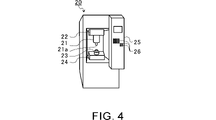
- FIG. 4 is an external view of a processing apparatus for a compressor impeller.
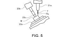
- FIG. 5 shows how the processing device processes the material for the compressor impeller.
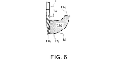
- FIG. 6 is a first explanatory diagram for explaining the processing of the compressor impeller.
- FIG. 7 is a second explanatory diagram for explaining the machining process of the compressor impeller.
- FIG. 8 is a third explanatory diagram for explaining the machining process of the compressor impeller.
- FIG. 9 is a fourth explanatory diagram for explaining the machining process of the compressor impeller.
- FIG. 1 is a schematic cross-sectional view of a supercharger.
- FIG. 2 is a perspective view of a compressor impeller.
- FIG. 3 is an explanatory diagram for explaining the shape of the blade.
- FIG. 10 is a flow chart for explaining the processing method (manufacturing method) of the compressor impeller.
- FIG. 11 is a partially enlarged view of the leading edge of the blade of this embodiment.
- FIG. 12 is a diagram for explaining the shape of the leading edge of this embodiment.
- FIG. 1 is a schematic cross-sectional view of the turbocharger TC.
- the direction of arrow L shown in FIG. 1 is assumed to be the left side of turbocharger TC.
- the direction of the arrow R shown in FIG. 1 will be described as the right side of the supercharger TC.
- the supercharger TC includes a supercharger body 1 .
- the supercharger body 1 includes a bearing housing 2 , a turbine housing 4 and a compressor housing 6 .
- the turbine housing 4 is connected to the left side of the bearing housing 2 by fastening bolts 3 .
- the compressor housing 6 is connected to the right side of the bearing housing 2 by fastening bolts 5 .
- a bearing hole 2 a is formed in the bearing housing 2 .
- the bearing hole 2a penetrates the bearing housing 2 in the lateral direction of the supercharger TC.
- a bearing is arranged in the bearing hole 2a.
- the bearing is a full floating bearing.
- the bearings may be other bearings such as semi-floating bearings and rolling bearings.
- the shaft 7 is rotatably supported by bearings.
- a compressor impeller 8 (impeller) is provided at the right end of the shaft 7 .
- a compressor impeller 8 is rotatably housed in the compressor housing 6 .
- a turbine wheel 9 is provided at the left end of the shaft 7 .
- the turbine wheel 9 is rotatably housed in the turbine housing 4 .
- “axial”, “radial” and “circumferential” of shaft 7, compressor impeller 8 and turbine wheel 9 are simply referred to as “axial”, “radial” and “circumferential” respectively. can be
- An intake port 10 is formed in the compressor housing 6 .
- the intake port 10 opens on the right side of the supercharger TC.
- the intake port 10 is connected to an air cleaner (not shown).
- a diffuser flow path 11 is formed by the surfaces of the bearing housing 2 and the compressor housing 6 .
- the diffuser channel 11 pressurizes the air.
- the diffuser flow path 11 is formed in an annular shape.
- the diffuser flow path 11 communicates with the intake port 10 via the compressor impeller 8 on the inner side in the radial direction.
- a surface of the inner surface of the compressor housing 6 that faces the compressor impeller 8 in the radial direction is formed as a shroud surface 6a.
- a compressor scroll flow path 12 is provided in the compressor housing 6 .
- the compressor scroll channel 12 is positioned, for example, radially outside the diffuser channel 11 .
- the compressor scroll channel 12 communicates with the intake port of the engine (not shown) and the diffuser channel 11 .
- intake air is pressurized and accelerated while flowing between the blades of the compressor impeller 8 .
- the pressurized and accelerated air is further pressurized in the diffuser passage 11 and the compressor scroll passage 12 .
- the pressurized air is directed to the engine intake.
- a centrifugal compressor CC is configured by such a compressor housing 6 and bearing housing 2 .
- the centrifugal compressor CC is mounted on the supercharger TC.
- the centrifugal compressor CC may be incorporated in a device other than the supercharger TC, or may be a single unit.
- a discharge port 13 is formed in the turbine housing 4 .
- the discharge port 13 opens on the left side of the supercharger TC.
- the discharge port 13 is connected to an exhaust gas purification device (not shown).
- a turbine scroll passage 14 and a communication passage 15 are formed in the turbine housing 4 .
- the turbine scroll passage 14 is located radially outside the communication passage 15, for example.
- the turbine scroll passage 14 communicates with a gas inlet (not shown). Exhaust gas discharged from an exhaust manifold of an engine (not shown) is guided to the gas inlet.
- the communication passage 15 connects the turbine scroll passage 14 and the discharge port 13 via the turbine wheel 9 .
- the exhaust gas guided from the gas inlet to the turbine scroll passage 14 is further guided to the discharge port 13 via the communication passage 15 and the turbine wheel 9 .
- the exhaust gas guided to the discharge port 13 rotates the turbine wheel 9 in the flow process.
- the rotational force of the turbine impeller 9 is transmitted to the compressor impeller 8 via the shaft 7. As the compressor impeller 8 rotates, the air is pressurized as described above. Air is thus directed to the intake of the engine.
- FIG. 2 is a perspective view of the compressor impeller 8.
- the compressor impeller 8 has a hub 16 (wheel) and a plurality of blades 17 .
- the hub 16 has a top surface 16a, a bottom surface 16b, an outer peripheral surface 16c, and a through hole 16d.
- the area of the top surface 16a is smaller than the area of the bottom surface 16b.
- the outer peripheral surface 16c is connected to the top surface 16a and the bottom surface 16b and extends radially outward from the top surface 16a toward the bottom surface 16b.
- the through hole 16d penetrates from the top surface 16a to the bottom surface 16b.
- the shaft 7 is inserted through the through hole 16d.
- the end of the shaft 7 protrudes from the upper surface 16a.
- a screw groove is formed in the end of the shaft 7 protruding from the upper surface 16a.
- a hub 16 is provided at one end of the shaft 7 by fastening a nut to this thread groove.
- the hub 16 is a rotating body that rotates about the center of the through hole 16d as a rotation axis.
- the blade 17 is a thin plate-shaped member integrally formed with the hub 16 .
- a plurality of blades 17 are arranged on the outer peripheral surface 16c of the hub 16 so as to be spaced apart from each other in the circumferential direction. Circumferential gaps between adjacent blades 17 (between blades 17a) serve as flow paths for air (fluid).
- the blades 17 extend radially outward from the outer peripheral surface 16c of the hub 16 toward the shroud surface 6a (see FIG. 1) and are curved so as to be inclined in the circumferential direction.
- the blades 17 include full blades 18 (long blades) and half blades 19 (short blades) having a shorter axial length than the full blades 18 .
- Full blades 18 and half blades 19 are alternately arranged in the circumferential direction. In this way, by arranging the half blades 19 between the full blades 18, the turbocharger TC can improve the air suction efficiency compared to the case where the same number of the blades 17 are all the full blades 18. can.
- both full blade 18 and half blade 19 are indicated.
- FIG. 3 is an explanatory diagram for explaining the shape of the blades 17.
- the meridional shape of the blade 17 of this embodiment is indicated by a dashed line.
- the meridional shape is obtained by rotating the contour of one blade 17 around the rotation axis of the hub 16 without changing the radial position of the hub 16 and projecting it onto a plane parallel to the rotation axis of the hub 16.
- Shape. 3 the left-right direction is the axial direction of the shaft 7, the right side is the bottom surface 16b side of the hub 16, and the left side is the top surface 16a side of the hub 16. As shown in FIG. In FIG. In FIG. In FIG. 3, the left-right direction is the axial direction of the shaft 7, the right side is the bottom surface 16b side of the hub 16, and the left side is the top surface 16a side of the hub 16. As shown in FIG. In FIG. In FIG.
- the vertical direction is the span direction (blade length direction) of the blades 17, the upper side is the shroud surface 6a side (hereinafter simply referred to as the shroud side), and the lower side is the outer peripheral surface 16c side of the hub 16 (hereinafter simply referred to as the shroud side). hub side).
- the blade 17 has a leading edge 17b that is the upstream end in the flow direction of the air passing through the compressor impeller 8 (hereinafter simply referred to as the flow direction).
- the leading edge 17b which is one end of the half blade 19 in the axial direction, is positioned downstream in the flow direction from the leading edge 17b, which is one end of the full blade 18 in the axial direction.
- the blade 17 has a trailing edge 17c that is the downstream end in the flow direction.
- the blade surface 17d is a curved surface formed between the leading edge 17b and the trailing edge 17c of the blade 17 and facing the flow path formed between the blades 17a.
- leading edge 17b is approximately parallel to the radial direction.
- Trailing edge 17c is generally parallel to the axial direction.
- the blade surface 17d includes a leading edge 17b and a trailing edge 17c as end portions, and has a curved surface shape ( ruled surface). That is, the generatrix 17e is a straight line at any position in the movement trajectory of the straight line with respect to the ruled surface drawn by the movement trajectory of the straight line (line segment) connecting the shroud-side end and the hub-side end. be.
- the compressor impeller 8 is configured by a so-called busbar impeller.
- the manufacturing method (processing method) of the compressor impeller 8 will be described after the processing apparatus for the compressor impeller 8 is described.
- FIG. 4 is an external view of the processing device 20 for the compressor impeller 8.
- FIG. FIG. 5 shows how the processing device 20 processes the material M for the compressor impeller 8 .
- the processing device 20 is composed of, for example, a simultaneous 5-axis machining center. As shown in FIG. 4 , the processing device 20 includes a rotating section 21 , a moving section 22 , a holding section 23 , a moving section 24 , a control section 25 and an operating section 26 . As shown in FIG. 5, the rotating part 21 has a chuck part 21a that supports a tool T such as an end mill, and a motor (not shown). With the chuck portion 21a supporting the tool T, the power of the motor rotates the tool T together with the chuck portion 21a. The chuck portion 21a supports the tool T in a state in which the rotation axis of the chuck portion 21a coincides with the axial center of the tool T. As shown in FIG.
- the moving unit 22 is composed of, for example, an automatic stage that can be moved along three mutually orthogonal axes by a motor (not shown).
- the moving part 22 supports the rotating part 21 and can move the rotating part 21 in any direction of the three axes.
- the holding part 23 is composed of, for example, a clamp device.
- the holding portion 23 holds the material M of the compressor impeller 8 .
- the material M is pre-formed with a hole that serves as the through hole 16 d of the hub 16 .
- the holding part 23 has a first clamp 23a that holds the outer peripheral surface of the material M.
- a second clamp 23b is arranged on the side opposite to the first clamp 23a with the material M interposed therebetween.
- a pin 23c is fixed to the second clamp 23b.
- the pin 23c has a tapered shape with a smaller diameter toward the tip. The tip of the pin 23c is inserted through a hole in the material M that serves as the through hole 16d of the hub 16.
- a material M is clamped between the first clamp 23a and the pin 23c.
- the moving part 24 supports the holding part 23 .
- the moving part 24 can turn the material M together with the holding part 23 around two different axes by, for example, a motor (not shown).
- the relative positions and postures of the tool T and the material M can be changed with a high degree of freedom.
- the control unit 25 controls the rotation of the tool T by the rotating unit 21 and the relative positions and orientations of the tool T and the material M by the moving units 22 and 24 according to information such as a machining path input through the operation unit 26. Control.
- the processing flow of the compressor impeller 8 by the control unit 25 will be described in detail below.
- FIG. 6 is a first explanatory diagram for explaining the processing of the compressor impeller 8.
- FIG. 7 is a second explanatory diagram for explaining the processing of the compressor impeller 8.
- FIG. 8 is a third explanatory diagram for explaining the processing of the compressor impeller 8.
- FIG. 9 is a fourth explanatory diagram for explaining the processing of the compressor impeller 8. As shown in FIG. In FIGS. 6 to 9, the processing device 20 is omitted for easy understanding.
- the rotation axis direction of the tool T is aligned with the direction of the generatrix 17e, and the side surface Ta of the blade of the tool T is used to cut the material M of the compressor impeller 8.
- the control unit 25 controls the moving units 22 and 24 and the rotating unit 21, and as shown in FIGS. to cut the material M. That is, the control unit 25 rotates the tool T to cut the material M at the portion of the gap between the plurality of blades 17 (between the blades 17a) on the side surface Ta from the leading edge 17b toward the trailing edge 17c. At this time, the controller 25 continuously increases the tilt angle of the tool T in the direction in which the axial direction of the tool T approaches the direction of the trailing edge 17c from the leading edge 17b. Thus, the controller 25 cuts the blade surface 17d between the leading edge 17b and the trailing edge 17c of the blade 17 with the side surface Ta of the blade of the tool T. As shown in FIG.
- the direction of the rotation axis of the tool T is aligned with the direction intersecting the axial direction of the shaft 7 (span direction of the leading edge 17b), and the tip Tb of the blade of the tool T is used. A portion corresponding to the leading edge 17b of the material M is cut.
- the control unit 25 controls the moving units 22 and 24 and the rotating unit 21, rotates the tool T, and rotates the tip of the blade along the thickness direction of the blade 17 (blade thickness direction) as shown in FIG. A portion of the material M that will become the leading edge 17b is cut at Tb.
- the control unit 25 moves the tool T to a position adjacent to the cut portion in the span direction as indicated by the dashed line in FIG. A portion of the material M that will become the leading edge 17b is cut.
- the control unit 25 moves the tool T from the shroud-side end of the leading edge 17b to the hub-side end to cut the material M. As shown in FIG.
- the controller 25 cuts the leading edge 17b with the tip Tb of the blade of the tool T.
- FIG. 10 is a flowchart for explaining the processing method (manufacturing method) of the compressor impeller 8.
- FIG. 10 is executed by the control unit 25 of the processing device 20 .
- the controller 25 processes the blade surface 17d between the leading edge 17b and the trailing edge 17c of the blade 17 with the blade side Ta of the tool T (step S11).
- the controller 25 processes the leading edge 17b with the tip Tb of the blade of the tool T (step S12).
- the blades 17 of the compressor impeller 8 are formed.
- the order of machining is not limited to this, and for example, after machining the leading edge 17b (step S12), the blade surface 17d may be machined (step S11).
- FIG. 11 is a partially enlarged view of the leading edge 17b of the blade 17 of this embodiment.
- the leading edge 17b of this embodiment is cut by the tip Tb of the blade of the tool T that moves along the thickness direction of the blade 17.
- the leading edge 17b is formed with a plurality of recessed portions 30 that are adjacent and continuous along the span direction.
- the plurality of depressions 30 are, for example, grooves extending in a direction crossing (perpendicular to) the span direction of the leading edge 17b.
- the recessed portion 30 has a shape that depends on the shape of the tip Tb of the blade of the tool T. As shown in FIG.
- FIG. 12 is a diagram for explaining the shape of the leading edge 17b of this embodiment.
- the shape of the leading edge 17b of this embodiment has a non-linear shape different from the straight line LI (broken line in FIG. 11) connecting the shroud-side end SH and the hub-side end HB.
- Nonlinear shapes include, for example, circular arc shapes, elliptical arc shapes, curved shapes, and the like.
- the leading edge 17b has an intermediate portion MD between the shroud-side end SH and the hub-side end HB.
- the leading edge 17b has an arcuate shape in which the middle portion MD is located on the rear side in the rotational direction of the compressor impeller 8 with respect to the shroud-side end portion SH and the hub-side end portion HB.
- the center in the span direction of the leading edge 17b is positioned furthest to the rear in the rotational direction with respect to the shroud-side end SH and the hub-side end HB.
- the leading edge 17b has an arcuate shape that protrudes rearward in the rotational direction of the compressor impeller 8 .
- leading edge 117b has an arc shape in which intermediate portion MD is positioned forward in the rotational direction of compressor impeller 8 with respect to shroud-side end portion SH and hub-side end portion HB. Specifically, the center in the span direction of the leading edge 117b is positioned furthest forward in the rotational direction with respect to the shroud-side end SH and the hub-side end HB. Thus, the leading edge 117b has an arcuate shape that protrudes forward in the rotational direction of the compressor impeller 8 .
- the blade surface 17d of the blade 17 of this embodiment is machined by the side surface Ta of the blade of the tool T.
- the machining time can be shortened.
- leading edges 17b and 117b of the blades 17 of this embodiment are machined by the tip Tb of the blade of the tool T.
- the tip Tb of the blade of the tool T does not extend linearly like the side Ta. Therefore, by processing with the tip Tb of the blade of the tool T, the shape of the leading edges 17b, 117b can be made into a non-linear shape different from the straight line LI connecting the shroud-side end SH and the hub-side end HB. can. As a result, the flow collision loss at the leading edges 17b, 117b can be reduced.
- the blade surface 17d is machined by the side surface Ta of the tool T and the leading edge 17b is machined by the tip Tb of the tool T has been explained.
- the present disclosure is not limited to this, and in addition to the leading edge 17b, part of the blade surface 17d may be processed by the tip Tb of the tool T.
- the leading edge 17b side of the blade surface 17d may be machined with the tip Tb of the tool T
- the trailing edge 17c side of the blade surface 17d may be machined with the side surface Ta of the tool T.
Landscapes
- Engineering & Computer Science (AREA)
- Mechanical Engineering (AREA)
- General Engineering & Computer Science (AREA)
- Structures Of Non-Positive Displacement Pumps (AREA)
Priority Applications (4)
| Application Number | Priority Date | Filing Date | Title |
|---|---|---|---|
| JP2023516044A JP7563583B2 (ja) | 2021-04-22 | 2022-01-19 | インペラ、遠心圧縮機、および、インペラの製造方法 |
| CN202280009933.XA CN116710660A (zh) | 2021-04-22 | 2022-01-19 | 叶轮、离心压缩机以及叶轮的制造方法 |
| DE112022000431.2T DE112022000431T5 (de) | 2021-04-22 | 2022-01-19 | Laufrad, Zentrifugalkompressor und Verfahren zum Herstellen eines Laufrads |
| US18/349,228 US20230349388A1 (en) | 2021-04-22 | 2023-07-10 | Impeller, centrifugal compressor, and method for manufacturing impeller |
Applications Claiming Priority (2)
| Application Number | Priority Date | Filing Date | Title |
|---|---|---|---|
| JP2021-072886 | 2021-04-22 | ||
| JP2021072886 | 2021-04-22 |
Related Child Applications (1)
| Application Number | Title | Priority Date | Filing Date |
|---|---|---|---|
| US18/349,228 Continuation US20230349388A1 (en) | 2021-04-22 | 2023-07-10 | Impeller, centrifugal compressor, and method for manufacturing impeller |
Publications (1)
| Publication Number | Publication Date |
|---|---|
| WO2022224512A1 true WO2022224512A1 (ja) | 2022-10-27 |
Family
ID=83722044
Family Applications (1)
| Application Number | Title | Priority Date | Filing Date |
|---|---|---|---|
| PCT/JP2022/001768 Ceased WO2022224512A1 (ja) | 2021-04-22 | 2022-01-19 | インペラ、遠心圧縮機、および、インペラの製造方法 |
Country Status (5)
| Country | Link |
|---|---|
| US (1) | US20230349388A1 (https=) |
| JP (1) | JP7563583B2 (https=) |
| CN (1) | CN116710660A (https=) |
| DE (1) | DE112022000431T5 (https=) |
| WO (1) | WO2022224512A1 (https=) |
Citations (11)
| Publication number | Priority date | Publication date | Assignee | Title |
|---|---|---|---|---|
| JPS62213913A (ja) * | 1986-03-17 | 1987-09-19 | Mitsubishi Heavy Ind Ltd | タ−ビン動翼の加工方法 |
| JPH03107600A (ja) * | 1989-09-20 | 1991-05-07 | Matsushita Electric Ind Co Ltd | 電動送風機 |
| JPH0454997U (https=) * | 1990-09-19 | 1992-05-12 | ||
| JP2002036020A (ja) * | 2000-07-31 | 2002-02-05 | Ishikawajima Harima Heavy Ind Co Ltd | 大型インペラの加工方法 |
| JP2010269417A (ja) * | 2009-05-22 | 2010-12-02 | Fanuc Ltd | インペラ加工機 |
| JP2013139753A (ja) * | 2012-01-05 | 2013-07-18 | Mitsubishi Heavy Ind Ltd | インペラ及びこれを備えたロータ並びにインペラの製造方法 |
| JP2014134115A (ja) * | 2013-01-09 | 2014-07-24 | Fanuc Ltd | 複数の直線により形状が定義されるインペラの形成方法およびインペラ |
| WO2015002066A1 (ja) * | 2013-07-04 | 2015-01-08 | 株式会社Ihi | コンプレッサインペラ、遠心圧縮機、コンプレッサインペラの加工方法、および、コンプレッサインペラの加工装置 |
| JP2015017566A (ja) * | 2013-07-11 | 2015-01-29 | ファナック株式会社 | 直線素からなる面で構成された翼を持つインペラ及びその加工方法 |
| JP2017172344A (ja) * | 2016-03-18 | 2017-09-28 | 三菱重工業株式会社 | インペラ、回転機械、およびインペラの製造方法 |
| JP2019153298A (ja) * | 2018-02-28 | 2019-09-12 | ダイキン工業株式会社 | 加工品の製造方法、工具経路計算方法、加工品、及びインペラー |
Family Cites Families (9)
| Publication number | Priority date | Publication date | Assignee | Title |
|---|---|---|---|---|
| US7334331B2 (en) * | 2003-12-18 | 2008-02-26 | General Electric Company | Methods and apparatus for machining components |
| JP4641464B2 (ja) | 2005-08-19 | 2011-03-02 | アイコクアルファ株式会社 | チタン製圧縮機翼車の製造方法 |
| EP2045444B1 (de) * | 2007-10-01 | 2015-11-18 | Alstom Technology Ltd | Laufschaufel, Verfahren zur Herstellung einer Laufschaufel, sowie Verdichter mit einer solchen Laufschaufel |
| DE102009004791A1 (de) * | 2009-01-13 | 2010-07-15 | Rolls-Royce Deutschland Ltd & Co Kg | Verfahren zur Herstellung der Schaufelspitzen von in BLISK-Bauweise gefertigten Laufrädern |
| US8951009B2 (en) * | 2011-05-23 | 2015-02-10 | Ingersoll Rand Company | Sculpted impeller |
| JP6388772B2 (ja) * | 2014-02-25 | 2018-09-12 | 三菱重工業株式会社 | 遠心圧縮機およびディフューザ製造方法 |
| US20180258945A1 (en) * | 2017-03-13 | 2018-09-13 | Borgwarner Inc. | Turbocharger compressor impeller with serrated leading edges |
| JP7005393B2 (ja) * | 2018-03-09 | 2022-01-21 | 三菱重工業株式会社 | ディフューザベーン及び遠心圧縮機 |
| JP2021072886A (ja) | 2021-01-05 | 2021-05-13 | 智 小野寺 | Pd22koro2 光線照射装置による血液中ウイルス等へのpd治療法の対処応用の構造 その2 ならびにpd光学シートとpd線の応用例 |
-
2022
- 2022-01-19 WO PCT/JP2022/001768 patent/WO2022224512A1/ja not_active Ceased
- 2022-01-19 CN CN202280009933.XA patent/CN116710660A/zh active Pending
- 2022-01-19 JP JP2023516044A patent/JP7563583B2/ja active Active
- 2022-01-19 DE DE112022000431.2T patent/DE112022000431T5/de active Pending
-
2023
- 2023-07-10 US US18/349,228 patent/US20230349388A1/en not_active Abandoned
Patent Citations (11)
| Publication number | Priority date | Publication date | Assignee | Title |
|---|---|---|---|---|
| JPS62213913A (ja) * | 1986-03-17 | 1987-09-19 | Mitsubishi Heavy Ind Ltd | タ−ビン動翼の加工方法 |
| JPH03107600A (ja) * | 1989-09-20 | 1991-05-07 | Matsushita Electric Ind Co Ltd | 電動送風機 |
| JPH0454997U (https=) * | 1990-09-19 | 1992-05-12 | ||
| JP2002036020A (ja) * | 2000-07-31 | 2002-02-05 | Ishikawajima Harima Heavy Ind Co Ltd | 大型インペラの加工方法 |
| JP2010269417A (ja) * | 2009-05-22 | 2010-12-02 | Fanuc Ltd | インペラ加工機 |
| JP2013139753A (ja) * | 2012-01-05 | 2013-07-18 | Mitsubishi Heavy Ind Ltd | インペラ及びこれを備えたロータ並びにインペラの製造方法 |
| JP2014134115A (ja) * | 2013-01-09 | 2014-07-24 | Fanuc Ltd | 複数の直線により形状が定義されるインペラの形成方法およびインペラ |
| WO2015002066A1 (ja) * | 2013-07-04 | 2015-01-08 | 株式会社Ihi | コンプレッサインペラ、遠心圧縮機、コンプレッサインペラの加工方法、および、コンプレッサインペラの加工装置 |
| JP2015017566A (ja) * | 2013-07-11 | 2015-01-29 | ファナック株式会社 | 直線素からなる面で構成された翼を持つインペラ及びその加工方法 |
| JP2017172344A (ja) * | 2016-03-18 | 2017-09-28 | 三菱重工業株式会社 | インペラ、回転機械、およびインペラの製造方法 |
| JP2019153298A (ja) * | 2018-02-28 | 2019-09-12 | ダイキン工業株式会社 | 加工品の製造方法、工具経路計算方法、加工品、及びインペラー |
Also Published As
| Publication number | Publication date |
|---|---|
| US20230349388A1 (en) | 2023-11-02 |
| JPWO2022224512A1 (https=) | 2022-10-27 |
| DE112022000431T5 (de) | 2023-11-02 |
| JP7563583B2 (ja) | 2024-10-08 |
| CN116710660A (zh) | 2023-09-05 |
Similar Documents
| Publication | Publication Date | Title |
|---|---|---|
| EP2351920B1 (en) | Turbocharger | |
| US8512000B2 (en) | Exhaust gas turbocharger | |
| JP4047330B2 (ja) | 独立通路ディフューザ | |
| US20160010657A1 (en) | Compressor wheel, centrifugal compressor, machining method for compressor wheel, and machining apparatus for compressor wheel | |
| US11933314B2 (en) | Compressor wheel | |
| JP2008115855A (ja) | 可変ステータベーンアッセンブリおよびガスタービンエンジン用圧縮機 | |
| US10907654B2 (en) | Rotor disk for an exhaust turbocharger, exhaust turbocharger and method for balancing a rotor assembly for an exhaust turbocharger | |
| CN217999952U (zh) | 压缩机叶轮和车辆中的增压设备 | |
| EP3351762B1 (en) | Variable nozzle unit and variable displacement-type supercharger | |
| CN104508277B (zh) | 可变喷嘴单元以及可变容量型增压器 | |
| US11655728B2 (en) | Rotary machine | |
| JPWO2018088363A1 (ja) | 可変ノズルユニットおよび過給機 | |
| WO2022224512A1 (ja) | インペラ、遠心圧縮機、および、インペラの製造方法 | |
| JP2020537076A (ja) | 排気ガス過給機のための羽根車、排気ガス過給機、及び排気ガス過給機のための回転体アセンブリのバランス調整方法 | |
| JP2016108994A (ja) | 圧縮機インペラ、遠心圧縮機、及び過給機 | |
| JP3305204B2 (ja) | 輻流羽根車の加工方法 | |
| CN1058548C (zh) | 减小涡轮叶片应力的方法及低应力涡轮叶片和涡轮转子 | |
| EP3693608B1 (en) | Method of manufacturing centrifugal rotary machine and centrifugal rotary machine | |
| US11047393B1 (en) | Multi-stage centrifugal compressor, casing, and return vane | |
| JP2000110771A (ja) | ターボ分子ポンプ | |
| US20220389936A1 (en) | Impeller of centrifugal compressor, centrifugal compressor, and turbocharger | |
| US20260125985A1 (en) | Turbine and manufacturing method of turbine | |
| WO2024095525A1 (ja) | タービン | |
| WO2024199825A1 (en) | Impeller for a compressor, compressor and turbocharger | |
| JP2023007748A (ja) | 遠心式回転装置 |
Legal Events
| Date | Code | Title | Description |
|---|---|---|---|
| 121 | Ep: the epo has been informed by wipo that ep was designated in this application |
Ref document number: 22791298 Country of ref document: EP Kind code of ref document: A1 |
|
| ENP | Entry into the national phase |
Ref document number: 2023516044 Country of ref document: JP Kind code of ref document: A |
|
| WWE | Wipo information: entry into national phase |
Ref document number: 202280009933.X Country of ref document: CN |
|
| WWE | Wipo information: entry into national phase |
Ref document number: 112022000431 Country of ref document: DE |
|
| 122 | Ep: pct application non-entry in european phase |
Ref document number: 22791298 Country of ref document: EP Kind code of ref document: A1 |