WO2022209016A1 - ステアリング装置 - Google Patents
ステアリング装置 Download PDFInfo
- Publication number
- WO2022209016A1 WO2022209016A1 PCT/JP2021/044749 JP2021044749W WO2022209016A1 WO 2022209016 A1 WO2022209016 A1 WO 2022209016A1 JP 2021044749 W JP2021044749 W JP 2021044749W WO 2022209016 A1 WO2022209016 A1 WO 2022209016A1
- Authority
- WO
- WIPO (PCT)
- Prior art keywords
- shaft
- pinion gear
- rack shaft
- rack
- holding force
- Prior art date
- Legal status (The legal status is an assumption and is not a legal conclusion. Google has not performed a legal analysis and makes no representation as to the accuracy of the status listed.)
- Ceased
Links
Images

Classifications
-
- B—PERFORMING OPERATIONS; TRANSPORTING
- B62—LAND VEHICLES FOR TRAVELLING OTHERWISE THAN ON RAILS
- B62D—MOTOR VEHICLES; TRAILERS
- B62D3/00—Steering gears
- B62D3/02—Steering gears mechanical
- B62D3/12—Steering gears mechanical of rack-and-pinion type
-
- B—PERFORMING OPERATIONS; TRANSPORTING
- B62—LAND VEHICLES FOR TRAVELLING OTHERWISE THAN ON RAILS
- B62D—MOTOR VEHICLES; TRAILERS
- B62D5/00—Power-assisted or power-driven steering
- B62D5/04—Power-assisted or power-driven steering electrical, e.g. using an electric servo-motor connected to, or forming part of, the steering gear
Definitions
- the present invention relates to steering devices.
- JP2013-241051A describes a rack-and-pinion type steering device equipped with a preload mechanism that presses the rack toward the pinion.
- the preload mechanism is constructed by sequentially inserting a rack guide, a preload spring, and an adjustment screw into the cylindrical portion of the housing. By biasing the rack guide toward the rack with the preload spring, the rack is pressed toward the pinion. This prevents backlash from occurring between the rack and pinion.
- the rack is biased by the preload mechanism to generate a holding force for holding the pinion to the rack.
- a preload mechanism such as that described in JP2013-241051A is generally configured to increase the holding force in order to prevent abnormal noise due to backlash.
- the steering device described in JP2013-241051A is a so-called single pinion type steering device, and the preload mechanism as described in JP2013-241051A can also be applied to each of the two pinions of the dual pinion type steering device. Conceivable.
- the holding force is increased in order to prevent abnormal noise due to backlash
- the reaction force that each pinion receives from the rack becomes excessive, making it difficult to move the rack. Therefore, there is a possibility that the steerability of the steering device is deteriorated.
- it is conceivable to reduce the holding force but in this case, there is a possibility that abnormal noise due to backlash cannot be sufficiently prevented.
- An object of the present invention is to improve steerability while preventing abnormal noise from occurring in a dual-pinion steering device.
- a first shaft member that rotates in response to steering of a steering member by a driver; and a second shaft member that is provided on the first shaft member and rotates together with the first shaft member a first pinion gear, a second shaft member that is rotationally driven by a motor, a second pinion gear that is provided on the second shaft member and rotates together with the second shaft member, and a rack gear that meshes with the first pinion gear and the second pinion gear.
- a rack shaft for steering a wheel a first biasing mechanism for biasing the rack shaft toward the first pinion gear
- a second biasing mechanism for biasing the rack shaft toward the second pinion gear.
- FIG. 1 is a configuration diagram of an electric power steering apparatus according to this embodiment.
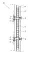
- FIG. 2 is a partial cross-sectional view of the rack shaft.
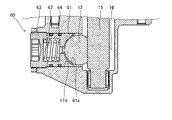
- FIG. 3 is a partial cross-sectional view of the vicinity of the first biasing mechanism.
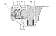
- FIG. 4 is a partial cross-sectional view of the vicinity of the second biasing mechanism.
- an electric power steering device 100 includes a steering shaft 11 as a first shaft member that rotates in accordance with steering of a steering wheel 1 as a steering member by a driver, and a steering shaft 11 that is provided on the steering shaft 11. 11, and a rack shaft 12 having a rack gear 12a meshing with the first pinion gear 16 and steering the wheel 2.
- the steering shaft 11 includes an input shaft 13 that rotates as the driver operates the steering wheel 1, an output shaft 15 that displaces the rack shaft 12, and a torsion bar that connects the input shaft 13 and the output shaft 15. 14 and .
- the rack shaft 12 is a shaft-shaped member that extends in the left-right direction of the vehicle and is connected to the wheels 2 via tie rods 5 and knuckle arms 4 .
- the output shaft 15 and the rack shaft 12 are connected to each other via a rack and pinion mechanism consisting of a first pinion gear 16 provided at the end of the output shaft 15 and a rack gear 12 a provided on the rack shaft 12 .
- the torque of the output shaft 15 is converted into a load in the axial direction of the rack shaft 12 and transmitted to the rack shaft 12 via the first pinion gear 16 and the rack gear 12a that mesh with each other.
- the rack shaft 12 is displaced in the axial direction by the transmitted torque, and the wheels 2 are steered via the tie rods 5 .
- the electric power steering apparatus 100 includes an electric motor 21 as a motor that is a power source for steering assist torque, a drive shaft 22 that is rotationally driven by the electric motor 21, and is provided on the drive shaft 22.
- a second pinion gear 23 that rotates together with the drive shaft 22 , and a reduction section 50 that reduces the speed of rotation of the electric motor 21 and transmits it to the drive shaft 22 .
- the reduction section 50 is a worm gear mechanism consisting of a worm shaft 51 driven by the electric motor 21 and a worm wheel 52 provided on the drive shaft 22 .
- the worm shaft 51 and the worm wheel 52 mesh with each other, and the torque of the electric motor 21 is transmitted to the drive shaft 22 via the worm shaft 51 and the worm wheel 52 .
- the second pinion gear 23 and the rack gear 12a mesh with each other, and the torque transmitted from the electric motor 21 to the drive shaft 22 is further transmitted to the rack shaft 12 via the second pinion gear 23 and the rack gear 12a.
- the electric power steering device 100 further includes a torque sensor 40 that detects torque acting on the torsion bar 14 and a controller 30 that controls driving of the electric motor 21 according to the detected value of the torque sensor 40 .
- the controller 30 includes a CPU (Central Processing Unit) that performs arithmetic processing, a ROM (Read-Only Memory) that stores control programs and the like executed by the CPU, and a RAM (random access memory) that stores the CPU's arithmetic results and the like. and a microcomputer including The controller 30 may be composed of a single microcomputer, or may be composed of a plurality of microcomputers.
- CPU Central Processing Unit
- ROM Read-Only Memory
- RAM random access memory
- the torque sensor 40 detects the steering torque applied to the input shaft 13 in accordance with the driver's steering operation, and outputs a voltage signal corresponding to the detected steering torque to the controller 30 .
- the controller 30 calculates the torque output by the electric motor 21 based on the voltage signal from the torque sensor 40, and controls driving of the electric motor 21 so that the torque is generated.
- the steering torque applied to the input shaft 13 is detected by the torque sensor 40, and the drive of the electric motor 21 is controlled by the controller 30 based on the detection result. It is possible to assist the driver's steering operation.
- the electric power steering device 100 is a dual-pinion steering device in which the steering torque by the driver and the steering assist torque by the electric motor 21 are independently input to the rack shaft 12 .
- the electric power steering device 100 houses a rack housing 17 as a case member that houses the rack shaft 12 , a shaft housing 18 that houses the steering shaft 11 , a reduction section 50 and a drive shaft 22 . a worm housing 53;
- the rack housing 17 includes an accommodation hole 17a formed through the axial direction to accommodate the rack shaft 12, and a first insertion hole 17b and a second insertion hole 17b which are open at one end on the outer peripheral surface and are formed so as to intersect the accommodation hole 17a. and two insertion holes 17c.
- the shaft housing 18 is connected to the rack housing 17 via bolts (not shown) such that the output shaft 15 is inserted through the first insertion hole 17b.
- the worm housing 53 is connected to the rack housing 17 via bolts (not shown) such that the drive shaft 22 is inserted through the second insertion hole 17c.
- the electric power steering device 100 includes a first biasing mechanism 60 that biases the rack shaft 12 toward the first pinion gear 16 .
- the first biasing mechanism 60 is housed in a first housing portion 17 d provided in the rack housing 17 .
- the rack housing 17 has a first accommodating portion 17d that accommodates the first biasing mechanism 60.
- the first accommodating portion 17 d is a through hole extending perpendicularly to the rack shaft 12 and the output shaft 15 and opening to the inner peripheral surface of the accommodating hole 17 a and the outer peripheral surface of the rack housing 17 .
- the first biasing mechanism 60 includes a first yoke 61 as a first contact portion that contacts the rack shaft 12 and a first biasing member that biases the first yoke 61 toward the rack shaft 12 . It has a spring 62 , a first cover 63 that closes the opening of the first accommodating portion 17 d of the rack housing 17 , and an O-ring 64 as an elastic member provided on the outer peripheral surface of the first yoke 61 .
- the first yoke 61 is slidably accommodated in the first accommodating portion 17d.
- the first yoke 61 is provided with a contact surface 61a along the outer peripheral surface of the rack shaft 12, and the rack shaft 12 is accommodated in contact with the contact surface 61a.
- the O-ring 64 is provided between the outer peripheral surface of the first yoke 61 and the inner peripheral surface of the first housing portion 17d to seal the gap therebetween.
- the first spring 62 is arranged so that its central axis is perpendicular to the central axis of the rack shaft 12 . Also, the first cover 63 is attached to the rack housing 17 by being screwed onto a female screw (not shown) provided in the first accommodating portion 17d. A first spring 62 is provided in a compressed state between the first yoke 61 and the first cover 63 . Thereby, the first spring 62 biases the rack shaft 12 toward the first pinion gear 16 via the first yoke 61 .
- the electric power steering device 100 includes a second biasing mechanism 70 that biases the rack shaft 12 toward the second pinion gear 23 .
- the second biasing mechanism 70 is housed in a second housing portion 17e provided in the rack housing 17.
- the rack housing 17 has a second accommodation portion 17e that accommodates the second biasing mechanism 70 .
- the second accommodation portion 17 e is a through hole extending perpendicularly to the rack shaft 12 and the drive shaft 22 and opening to the inner peripheral surface of the accommodation hole 17 a and the outer peripheral surface of the rack housing 17 .
- the second biasing mechanism 70 includes a second yoke 71 as a second contact portion that contacts the rack shaft 12 and a second biasing member that biases the second yoke 71 toward the rack shaft 12 . It has a spring 72 , a second cover 73 that closes the opening of the second accommodating portion 17 e of the rack housing 17 , and an O-ring 74 as an elastic member provided on the outer peripheral surface of the second yoke 71 . Since the second biasing mechanism 70 has the same basic configuration as the first biasing mechanism 60, detailed description thereof will be omitted. Differences between the first biasing mechanism 60 and the second biasing mechanism 70 will be described later.
- the rack shaft 12 is urged by the first urging mechanism 60 and the second urging mechanism 70, so that the first pinion gear 16 and the second pinion gear 23 are held by the rack shaft 12.
- holding force is generated.
- the holding force in this embodiment indicates the force acting on the first pinion gear 16 and the second pinion gear 23 through the rack shaft 12 .
- a force acts on the first pinion gear 16 and the second pinion gear 23 through the rack shaft 12 from the first biasing mechanism 60 and the second biasing mechanism 70 .
- force acts on the first pinion gear 16 and the second pinion gear 23 from the rack shaft 12 as a reaction force to the force input to the rack shaft 12 from itself.
- the holding force in this embodiment is the sum of the above two forces.
- an urging mechanism that urges the rack shaft toward the pinion gear is configured so that the pinion gear is held by the rack shaft with a large holding force in order to prevent the generation of abnormal noise due to backlash.
- increasing the holding force with which each pinion is held by the rack increases the reaction force that each pinion receives from the rack, causing the rack shaft to move due to the input from each pinion gear. becomes difficult. Therefore, there is a possibility that the steerability of the electric power steering apparatus will deteriorate. In order to deal with this, it is conceivable to reduce the holding force with which each pinion gear is held by the rack shaft, but in this case, there is a possibility that abnormal noise due to backlash cannot be sufficiently prevented.
- the rack shaft 12 is urged by the first urging mechanism 60 so that the first pinion gear 16 is held by the rack shaft 12 with a first holding force.
- the second holding force by which the second pinion gear 23 is held on the rack shaft 12 by urging the rack shaft 12 by the second urging mechanism 70 is urged by the rack shaft 12 so that the rack shaft 12 with a first holding force.
- the first holding force can be adjusted by changing the set load of the first spring 62, for example. This is because the force acting on the first pinion gear 16 through the rack shaft 12 changes as the biasing force of the first spring 62 changes.
- the set load of the first spring 62 is increased, the biasing force of the first spring 62 is increased, and the force acting on the first pinion gear 16 through the rack shaft 12 is increased. Therefore, the first holding force increases.
- the second holding force can also be adjusted by changing the set load of the second spring 72 . In this manner, the electric power steering apparatus 100 can individually set and optimize the first holding force and the second holding force by the members constituting the first urging mechanism 60 and the second urging mechanism 70. can be done.
- the set load of the first spring 62 is smaller than the set load of the second spring 72.
- the first holding force is less than the second holding force. That is, since the reaction force that the first pinion gear 16 receives from the rack shaft 12 is smaller than the reaction force that the second pinion gear 23 receives from the rack shaft 12 , the rack shaft 12 receives more input from the steering shaft 11 than the input from the drive shaft 22 . Easy to move with input from. As a result, the steerability of the electric power steering device 100 can be improved. Moreover, since the second holding force is higher than the first holding force, backlash that occurs between the rack shaft 12 and the second pinion gear 23 can be prevented. In this manner, the electric power steering apparatus 100 can achieve both prevention of abnormal noise and improvement of steering performance.
- the electric power steering device 100 is not limited to a structure in which the first holding force is smaller than the second holding force. With this configuration, the first holding force with which the first pinion gear 16 is held on the rack shaft 12 is different from the second holding force with which the second pinion gear 23 is held on the rack shaft 12.
- the forces transmitted to the rack shaft 12 can be optimized as a whole. Moreover, not only the magnitude of the force transmitted to the rack shaft 12 but also the manner in which the force is transmitted from the first biasing mechanism 60 and the second biasing mechanism 70 to the rack shaft 12 can be optimized. As a result, it is possible to achieve both prevention of abnormal noise from the electric power steering device 100 and improvement of steering performance.
- the electric power steering device 100 is configured such that the first holding force with which the first pinion gear 16 is held on the rack shaft 12 and the second holding force with which the second pinion gear 23 is held on the rack shaft 12 are different. , the forces transmitted to the rack shaft 12 as a whole can be optimized. As a result, it is possible to achieve both prevention of abnormal noise from the electric power steering device 100 and improvement of steering performance.
- the first holding force is smaller than the second holding force, so that the reaction force that the first pinion gear 16 receives from the rack shaft 12 is the reaction force that the second pinion gear 23 receives from the rack shaft 12 . smaller than the force. Therefore, the rack shaft 12 is more easily moved by the input from the steering shaft 11 than by the input from the drive shaft 22 . As a result, the steerability of the electric power steering device 100 can be improved. Moreover, since the second holding force is higher than the first holding force, backlash that occurs between the rack shaft 12 and the second pinion gear 23 can be prevented. In this manner, the electric power steering apparatus 100 can achieve both prevention of abnormal noise and improvement of steering performance.
- the electric power steering apparatus 100 of the above embodiment has a configuration in which the first holding force is smaller than the second holding force because the set load of the first spring 62 is smaller than the set load of the second spring 72 .
- the configuration of the electric power steering apparatus 100 is not limited to this, and may be a configuration in which the first holding force is smaller than the second holding force by other methods.
- the coefficient of friction of the first yoke 61 may be smaller than the coefficient of friction of the second yoke 71 .
- the first yoke 61 and the second yoke 71 are made of different materials, or the contact surface 61a and the contact surface 71a are coated with different materials.
- the coefficient of friction of the first yoke 61 may be smaller than the coefficient of friction of the second yoke 71 .
- the reaction force that the first pinion gear 16 receives from the rack shaft 12 is smaller than the reaction force that the second pinion gear 23 receives from the rack shaft 12 . Therefore, the first holding force becomes smaller than the second holding force, and the same effect as that of the above embodiment is exhibited.
- the electric power steering apparatus 100 of the above embodiment has a configuration in which the first holding force is smaller than the second holding force.
- the configuration of the electric power steering device 100 is not limited to this, as long as the first holding force and the second holding force are different.
- the set load of the first spring 62 and the set load of the second spring 72 may have different configurations.
- the coefficient of friction of the first yoke 61 and the coefficient of friction of the second yoke 71 may be configured differently. In these configurations, the first holding force and the second holding force can be individually set and optimized by the first spring 62 and the second spring 72 or the first yoke 61 and the second yoke 71. .
- An electric power steering device 100 as a steering device includes: a steering shaft 11 as a first shaft member that rotates according to steering of a steering wheel 1 as a steering member by a driver; a first pinion gear 16, a drive shaft 22 as a second shaft member that is rotationally driven by an electric motor 21 as a motor, a second pinion gear 23 that is provided on the drive shaft 22 and rotates together with the drive shaft 22, and a first pinion gear 16 and a rack gear 12a that meshes with the second pinion gear 23 to steer the wheel 2; a first biasing mechanism 60 that biases the rack shaft 12 toward the first pinion gear 16; A second biasing mechanism 70 biasing the second pinion gear 23 toward the second pinion gear 23 , and the first pinion gear 16 is held on the rack shaft 12 by biasing the rack shaft 12 by the first biasing mechanism 60 .
- the first holding force is different from the second holding force with which the second pinion gear 23 is held on the rack shaft 12 by urging the rack shaft 12 by the second urging mechanism 70
- the first holding force with which the first pinion gear 16 is held on the rack shaft 12 is different from the second holding force with which the second pinion gear 23 is held on the rack shaft 12, so that as a whole
- the forces transmitted to the rack shaft 12 can be optimized. As a result, it is possible to achieve both prevention of abnormal noise from the electric power steering device 100 and improvement of steering performance.
- the electric power steering apparatus 100 further includes a rack housing 17 as a case member that accommodates the rack shaft 12.
- the rack housing 17 includes a first accommodation portion 17d that accommodates the first biasing mechanism 60, a second
- the first urging mechanism 60 includes a first yoke 61 as a first abutting portion that abuts against the rack shaft 12, and the first yoke 61 as a rack shaft 12.
- the second biasing mechanism 70 has a first spring 62 as a first biasing member that biases toward the shaft 12 , and a second yoke 71 as a second contact portion that contacts the rack shaft 12 . and a second spring 72 as a second biasing member that biases the second yoke 71 toward the rack shaft 12 .
- the set load of the first spring 62 and the set load of the second spring 72 are different.
- the first holding force and the second holding force can be individually set and optimized by the first spring 62 and the second spring 72 .
- the coefficient of friction of the first yoke 61 and the coefficient of friction of the second yoke 71 are different.
- the first yoke 61 and the second yoke 71 can individually set and optimize the first holding force and the second holding force.
- the first holding force is smaller than the second holding force.
- the rack shaft 12 is easier to move with the input from the steering shaft 11 than the input from the drive shaft 22 .
- the steerability of the electric power steering device 100 can be improved.
- the second holding force is higher than the first holding force, backlash that occurs between the rack shaft 12 and the second pinion gear 23 can be prevented.
- the steering device may be of a so-called 2-assist type having a mechanism for assisting the steering operation on the steering shaft side as well.
Landscapes
- Engineering & Computer Science (AREA)
- Chemical & Material Sciences (AREA)
- Combustion & Propulsion (AREA)
- Transportation (AREA)
- Mechanical Engineering (AREA)
- Power Steering Mechanism (AREA)
Abstract
Description
上記実施形態の電動パワーステアリング装置100は、第一スプリング62のセット荷重が第二スプリング72のセット荷重よりも小さいことで、第一保持力が第二保持力よりも小さい構成である。電動パワーステアリング装置100の構成はこれに限らず、他の方法で第一保持力が第二保持力よりも小さい構成としてもよい。
上記実施形態の電動パワーステアリング装置100は、第一保持力が第二保持力よりも小さい構成である。前述のように、電動パワーステアリング装置100の構成はこれに限らず、第一保持力と、第二保持力と、が異なる構成であればよい。例えば、第一スプリング62のセット荷重と、第二スプリング72のセット荷重と、は異なる構成であってもよい。また、第一ヨーク61の摩擦係数と、第二ヨーク71の摩擦係数と、は異なる構成であってもよい。これらの構成では、第一スプリング62と第二スプリング72、または、第一ヨーク61と第二ヨーク71により、第一保持力と第二保持力とを個別に設定し、最適化することができる。
Claims (5)
- ステアリング装置であって、
運転者によるステアリング部材の操舵に応じて回転する第一シャフト部材と、
前記第一シャフト部材に設けられ前記第一シャフト部材と共に回転する第一ピニオンギヤと、
モータにより回転駆動される第二シャフト部材と、
前記第二シャフト部材に設けられ前記第二シャフト部材と共に回転する第二ピニオンギヤと、
前記第一ピニオンギヤ及び前記第二ピニオンギヤに噛み合うラックギヤを有し車輪を転舵するラックシャフトと、
前記ラックシャフトを前記第一ピニオンギヤに向けて付勢する第一付勢機構と、
前記ラックシャフトを前記第二ピニオンギヤに向けて付勢する第二付勢機構と、を備え、
前記第一付勢機構により前記ラックシャフトが付勢されることによって前記第一ピニオンギヤが前記ラックシャフトに保持される第一保持力と、前記第二付勢機構により前記ラックシャフトが付勢されることによって前記第二ピニオンギヤが前記ラックシャフトに保持される第二保持力と、は異なるステアリング装置。 - 請求項1に記載のステアリング装置であって、
前記ラックシャフトを収容するケース部材をさらに備え、
前記ケース部材は、
前記第一付勢機構を収容する第一収容部と、
前記第二付勢機構を収容する第二収容部と、を有し、
前記第一付勢機構は、前記ラックシャフトに当接する第一当接部と、前記第一当接部を前記ラックシャフトに向けて付勢する第一付勢部材と、を有し、
前記第二付勢機構は、前記ラックシャフトに当接する第二当接部と、前記第二当接部を前記ラックシャフトに向けて付勢する第二付勢部材と、を有するステアリング装置。 - 請求項2に記載のステアリング装置であって、
前記第一付勢部材のセット荷重と、前記第二付勢部材のセット荷重と、は異なるステアリング装置。 - 請求項2に記載のステアリング装置であって、
前記第一当接部の摩擦係数と、前記第二当接部の摩擦係数と、は異なるステアリング装置。 - 請求項1に記載のステアリング装置であって、
前記第一保持力は、前記第二保持力よりも小さいステアリング装置。
Priority Applications (2)
| Application Number | Priority Date | Filing Date | Title |
|---|---|---|---|
| CN202180096316.3A CN117062743A (zh) | 2021-03-31 | 2021-12-06 | 转向装置 |
| JP2023510227A JP7681096B2 (ja) | 2021-03-31 | 2021-12-06 | ステアリング装置 |
Applications Claiming Priority (2)
| Application Number | Priority Date | Filing Date | Title |
|---|---|---|---|
| JP2021-060897 | 2021-03-31 | ||
| JP2021060897 | 2021-03-31 |
Publications (1)
| Publication Number | Publication Date |
|---|---|
| WO2022209016A1 true WO2022209016A1 (ja) | 2022-10-06 |
Family
ID=83455847
Family Applications (1)
| Application Number | Title | Priority Date | Filing Date |
|---|---|---|---|
| PCT/JP2021/044749 Ceased WO2022209016A1 (ja) | 2021-03-31 | 2021-12-06 | ステアリング装置 |
Country Status (3)
| Country | Link |
|---|---|
| JP (1) | JP7681096B2 (ja) |
| CN (1) | CN117062743A (ja) |
| WO (1) | WO2022209016A1 (ja) |
Citations (5)
| Publication number | Priority date | Publication date | Assignee | Title |
|---|---|---|---|---|
| JP2014084002A (ja) * | 2012-10-24 | 2014-05-12 | Jtekt Corp | ステアリング装置 |
| WO2017010345A1 (ja) * | 2015-07-16 | 2017-01-19 | 本田技研工業株式会社 | デュアルピニオン式電動パワーステアリング装置 |
| JP2017154634A (ja) * | 2016-03-02 | 2017-09-07 | 株式会社ショーワ | 操舵装置 |
| JP2019089355A (ja) * | 2017-11-10 | 2019-06-13 | Kyb株式会社 | パワーステアリング装置 |
| JP2020001558A (ja) * | 2018-06-28 | 2020-01-09 | Kyb株式会社 | パワーステアリング装置 |
Family Cites Families (3)
| Publication number | Priority date | Publication date | Assignee | Title |
|---|---|---|---|---|
| US9272727B2 (en) * | 2012-10-24 | 2016-03-01 | Jtekt Corporation | Steering system |
| JP6535969B2 (ja) * | 2015-03-26 | 2019-07-03 | 日立オートモティブシステムズ株式会社 | 電動パワーステアリング装置 |
| US10167009B2 (en) * | 2016-05-25 | 2019-01-01 | Jtekt Corporation | Electric power steering system |
-
2021
- 2021-12-06 CN CN202180096316.3A patent/CN117062743A/zh active Pending
- 2021-12-06 WO PCT/JP2021/044749 patent/WO2022209016A1/ja not_active Ceased
- 2021-12-06 JP JP2023510227A patent/JP7681096B2/ja active Active
Patent Citations (5)
| Publication number | Priority date | Publication date | Assignee | Title |
|---|---|---|---|---|
| JP2014084002A (ja) * | 2012-10-24 | 2014-05-12 | Jtekt Corp | ステアリング装置 |
| WO2017010345A1 (ja) * | 2015-07-16 | 2017-01-19 | 本田技研工業株式会社 | デュアルピニオン式電動パワーステアリング装置 |
| JP2017154634A (ja) * | 2016-03-02 | 2017-09-07 | 株式会社ショーワ | 操舵装置 |
| JP2019089355A (ja) * | 2017-11-10 | 2019-06-13 | Kyb株式会社 | パワーステアリング装置 |
| JP2020001558A (ja) * | 2018-06-28 | 2020-01-09 | Kyb株式会社 | パワーステアリング装置 |
Also Published As
| Publication number | Publication date |
|---|---|
| CN117062743A (zh) | 2023-11-14 |
| JPWO2022209016A1 (ja) | 2022-10-06 |
| JP7681096B2 (ja) | 2025-05-21 |
Similar Documents
| Publication | Publication Date | Title |
|---|---|---|
| US7377194B2 (en) | Worm gear mechanism and electric power steering apparatus equipped with the worm gear mechanism | |
| US20140353070A1 (en) | Steering system | |
| KR20180095335A (ko) | 스토퍼 구조체 및 이를 구비한 스티어 바이 와이어식 조향 시스템 | |
| JP2010126031A (ja) | 車両用操舵装置 | |
| JP6845785B2 (ja) | パワーステアリング装置 | |
| WO2022209016A1 (ja) | ステアリング装置 | |
| JP4019936B2 (ja) | 電動式パワーステアリング装置 | |
| KR102325798B1 (ko) | 전동식 동력 보조 조향장치 | |
| JP4055520B2 (ja) | 車両用操舵装置 | |
| JPH05262243A (ja) | 電動式動力舵取装置 | |
| KR20110033034A (ko) | 전동식 동력 보조 조향장치의 감속기 | |
| US7159689B2 (en) | Electric power steering apparatus | |
| JP2003220958A (ja) | 電動パワーステアリング装置 | |
| JP4994272B2 (ja) | ラックアンドピニオン式ステアリング装置 | |
| JP4104346B2 (ja) | 車両用後輪操舵装置 | |
| JP2002154443A (ja) | 電動パワーステアリング装置 | |
| JP2004026102A (ja) | 電動式パワーステアリング装置 | |
| JP6277070B2 (ja) | 電動パワーステアリング装置 | |
| JP6375170B2 (ja) | 電動パワーステアリング装置 | |
| JP7316325B2 (ja) | ステアリング装置 | |
| JP5704055B2 (ja) | 車両操舵装置 | |
| JP4567502B2 (ja) | 電動パワーステアリング装置 | |
| JP3758556B2 (ja) | 車両の操舵装置 | |
| JP4062020B2 (ja) | 車両用操舵装置 | |
| JP2008230549A (ja) | 車両の操舵装置 |
Legal Events
| Date | Code | Title | Description |
|---|---|---|---|
| 121 | Ep: the epo has been informed by wipo that ep was designated in this application |
Ref document number: 21935169 Country of ref document: EP Kind code of ref document: A1 |
|
| DPE1 | Request for preliminary examination filed after expiration of 19th month from priority date (pct application filed from 20040101) | ||
| ENP | Entry into the national phase |
Ref document number: 2023510227 Country of ref document: JP Kind code of ref document: A |
|
| WWE | Wipo information: entry into national phase |
Ref document number: 202180096316.3 Country of ref document: CN |
|
| NENP | Non-entry into the national phase |
Ref country code: DE |
|
| 122 | Ep: pct application non-entry in european phase |
Ref document number: 21935169 Country of ref document: EP Kind code of ref document: A1 |