WO2022202273A1 - 電動送風機 - Google Patents
電動送風機 Download PDFInfo
- Publication number
- WO2022202273A1 WO2022202273A1 PCT/JP2022/009907 JP2022009907W WO2022202273A1 WO 2022202273 A1 WO2022202273 A1 WO 2022202273A1 JP 2022009907 W JP2022009907 W JP 2022009907W WO 2022202273 A1 WO2022202273 A1 WO 2022202273A1
- Authority
- WO
- WIPO (PCT)
- Prior art keywords
- air guide
- guide portion
- air
- electric blower
- diffuser
- Prior art date
Links
- 238000009423 ventilation Methods 0.000 claims abstract description 44
- 230000002093 peripheral effect Effects 0.000 claims abstract description 37
- 238000005192 partition Methods 0.000 description 41
- 230000000052 comparative effect Effects 0.000 description 22
- 229920005989 resin Polymers 0.000 description 7
- 239000011347 resin Substances 0.000 description 7
- 238000004804 winding Methods 0.000 description 6
- 238000007664 blowing Methods 0.000 description 5
- 230000008859 change Effects 0.000 description 5
- 238000002474 experimental method Methods 0.000 description 4
- 239000000463 material Substances 0.000 description 4
- 229910052751 metal Inorganic materials 0.000 description 4
- 239000002184 metal Substances 0.000 description 4
- 239000000470 constituent Substances 0.000 description 3
- 230000003247 decreasing effect Effects 0.000 description 3
- 238000010586 diagram Methods 0.000 description 3
- 238000004519 manufacturing process Methods 0.000 description 3
- 239000004412 Bulk moulding compound Substances 0.000 description 2
- 230000000694 effects Effects 0.000 description 2
- 238000005516 engineering process Methods 0.000 description 2
- 230000004907 flux Effects 0.000 description 2
- 239000007769 metal material Substances 0.000 description 2
- 230000004048 modification Effects 0.000 description 2
- 238000012986 modification Methods 0.000 description 2
- 229920001707 polybutylene terephthalate Polymers 0.000 description 2
- 230000009467 reduction Effects 0.000 description 2
- 238000000926 separation method Methods 0.000 description 2
- OKTJSMMVPCPJKN-UHFFFAOYSA-N Carbon Chemical compound [C] OKTJSMMVPCPJKN-UHFFFAOYSA-N 0.000 description 1
- 239000004677 Nylon Substances 0.000 description 1
- 229910000831 Steel Inorganic materials 0.000 description 1
- 229910052782 aluminium Inorganic materials 0.000 description 1
- XAGFODPZIPBFFR-UHFFFAOYSA-N aluminium Chemical compound [Al] XAGFODPZIPBFFR-UHFFFAOYSA-N 0.000 description 1
- 230000015572 biosynthetic process Effects 0.000 description 1
- 229910052799 carbon Inorganic materials 0.000 description 1
- 230000003993 interaction Effects 0.000 description 1
- 239000000696 magnetic material Substances 0.000 description 1
- 230000013011 mating Effects 0.000 description 1
- 238000000034 method Methods 0.000 description 1
- 229920001778 nylon Polymers 0.000 description 1
- 230000000149 penetrating effect Effects 0.000 description 1
- -1 polybutylene terephthalate Polymers 0.000 description 1
- 239000010959 steel Substances 0.000 description 1
- 229920005992 thermoplastic resin Polymers 0.000 description 1
- 229920001187 thermosetting polymer Polymers 0.000 description 1
- 229920006337 unsaturated polyester resin Polymers 0.000 description 1
Images


Classifications
-
- F—MECHANICAL ENGINEERING; LIGHTING; HEATING; WEAPONS; BLASTING
- F04—POSITIVE - DISPLACEMENT MACHINES FOR LIQUIDS; PUMPS FOR LIQUIDS OR ELASTIC FLUIDS
- F04D—NON-POSITIVE-DISPLACEMENT PUMPS
- F04D17/00—Radial-flow pumps, e.g. centrifugal pumps; Helico-centrifugal pumps
- F04D17/08—Centrifugal pumps
- F04D17/16—Centrifugal pumps for displacing without appreciable compression
- F04D17/165—Axial entry and discharge
-
- F—MECHANICAL ENGINEERING; LIGHTING; HEATING; WEAPONS; BLASTING
- F04—POSITIVE - DISPLACEMENT MACHINES FOR LIQUIDS; PUMPS FOR LIQUIDS OR ELASTIC FLUIDS
- F04D—NON-POSITIVE-DISPLACEMENT PUMPS
- F04D25/00—Pumping installations or systems
- F04D25/02—Units comprising pumps and their driving means
- F04D25/06—Units comprising pumps and their driving means the pump being electrically driven
- F04D25/0606—Units comprising pumps and their driving means the pump being electrically driven the electric motor being specially adapted for integration in the pump
-
- F—MECHANICAL ENGINEERING; LIGHTING; HEATING; WEAPONS; BLASTING
- F04—POSITIVE - DISPLACEMENT MACHINES FOR LIQUIDS; PUMPS FOR LIQUIDS OR ELASTIC FLUIDS
- F04D—NON-POSITIVE-DISPLACEMENT PUMPS
- F04D25/00—Pumping installations or systems
- F04D25/02—Units comprising pumps and their driving means
- F04D25/06—Units comprising pumps and their driving means the pump being electrically driven
- F04D25/0693—Details or arrangements of the wiring
-
- F—MECHANICAL ENGINEERING; LIGHTING; HEATING; WEAPONS; BLASTING
- F04—POSITIVE - DISPLACEMENT MACHINES FOR LIQUIDS; PUMPS FOR LIQUIDS OR ELASTIC FLUIDS
- F04D—NON-POSITIVE-DISPLACEMENT PUMPS
- F04D29/00—Details, component parts, or accessories
- F04D29/40—Casings; Connections of working fluid
- F04D29/42—Casings; Connections of working fluid for radial or helico-centrifugal pumps
- F04D29/4206—Casings; Connections of working fluid for radial or helico-centrifugal pumps especially adapted for elastic fluid pumps
- F04D29/4226—Fan casings
- F04D29/4253—Fan casings with axial entry and discharge
-
- F—MECHANICAL ENGINEERING; LIGHTING; HEATING; WEAPONS; BLASTING
- F04—POSITIVE - DISPLACEMENT MACHINES FOR LIQUIDS; PUMPS FOR LIQUIDS OR ELASTIC FLUIDS
- F04D—NON-POSITIVE-DISPLACEMENT PUMPS
- F04D29/00—Details, component parts, or accessories
- F04D29/40—Casings; Connections of working fluid
- F04D29/42—Casings; Connections of working fluid for radial or helico-centrifugal pumps
- F04D29/44—Fluid-guiding means, e.g. diffusers
- F04D29/441—Fluid-guiding means, e.g. diffusers especially adapted for elastic fluid pumps
- F04D29/444—Bladed diffusers
-
- H—ELECTRICITY
- H02—GENERATION; CONVERSION OR DISTRIBUTION OF ELECTRIC POWER
- H02K—DYNAMO-ELECTRIC MACHINES
- H02K5/00—Casings; Enclosures; Supports
- H02K5/04—Casings or enclosures characterised by the shape, form or construction thereof
- H02K5/08—Insulating casings
-
- H—ELECTRICITY
- H02—GENERATION; CONVERSION OR DISTRIBUTION OF ELECTRIC POWER
- H02K—DYNAMO-ELECTRIC MACHINES
- H02K7/00—Arrangements for handling mechanical energy structurally associated with dynamo-electric machines, e.g. structural association with mechanical driving motors or auxiliary dynamo-electric machines
- H02K7/14—Structural association with mechanical loads, e.g. with hand-held machine tools or fans
-
- H—ELECTRICITY
- H02—GENERATION; CONVERSION OR DISTRIBUTION OF ELECTRIC POWER
- H02K—DYNAMO-ELECTRIC MACHINES
- H02K9/00—Arrangements for cooling or ventilating
- H02K9/02—Arrangements for cooling or ventilating by ambient air flowing through the machine
- H02K9/04—Arrangements for cooling or ventilating by ambient air flowing through the machine having means for generating a flow of cooling medium
- H02K9/06—Arrangements for cooling or ventilating by ambient air flowing through the machine having means for generating a flow of cooling medium with fans or impellers driven by the machine shaft
-
- H—ELECTRICITY
- H02—GENERATION; CONVERSION OR DISTRIBUTION OF ELECTRIC POWER
- H02K—DYNAMO-ELECTRIC MACHINES
- H02K9/00—Arrangements for cooling or ventilating
- H02K9/28—Cooling of commutators, slip-rings or brushes e.g. by ventilating
Definitions
- This disclosure relates to an electric blower.
- Electric blowers with rotating fans are used in various electric appliances such as vacuum cleaners.
- a centrifugal fan capable of obtaining a high suction pressure is adopted as a rotating fan for an electric blower mounted on a vacuum cleaner.
- An electric blower using a centrifugal fan for example, includes an electric motor, a centrifugal fan, an air guide, a fan case, and a motor case.
- the centrifugal fan is attached to the rotating shaft of the electric motor. Air sent from the centrifugal fan flows into the air guide.
- a fan case covers the centrifugal fan and the air guide.
- the motor case accommodates the electric motor.
- the air guide has diffuser vanes provided on the surface facing the centrifugal fan and guide vanes provided on the surface opposite to the centrifugal fan.
- the air guide is separated into two parts, a first member having diffuser blades and a second member having guide blades (return blades). Coupled configurations are known (see, for example, US Pat.
- the diffuser blades of the air guide it is necessary to change the number of blades, blade shape, blade spacing, etc. for each type of electric blower according to the required characteristics of the electric blower. In this case, in order to obtain the optimum efficiency as an electric blower, it is desirable to have a specification in which the diffuser blades and the guide blades are interlocked.
- the inner surface of the extension blade is close to the outer peripheral edge of the second air guide portion.
- extension wings extend to a position exceeding half the height of the guide wings.
- the electric blower it is possible to suppress a decrease in efficiency even if the diffuser blades and the guide blades are not combined together.
- the electric motor 10 is a motor that rotates the centrifugal fan 20.
- Motor 10 is a brushed commutator motor.
- Electric motor 10 includes rotor 11 , stator 12 , rotating shaft 13 , commutator 14 , brushes 15 , first bearing 16 and second bearing 17 .
- the rotor 11 (rotor) has a rotating shaft 13 .
- the rotor 11 rotates about the rotating shaft 13 by the magnetic force of the stator 12 .
- the rotor 11 is an inner rotor.
- the rotor 11 is arranged inside the stator 12 as shown in FIGS. Specifically, the rotor 11 is surrounded by the stator 12 with a small air gap therebetween.
- the brushes 15 are power supply brushes for supplying power to the rotor 11 by contacting the commutator 14 .
- the brushes 15 supply the armature current to the commutator 14 by contacting the commutator bars of the commutator 14 .
- the brush 15 is a carbon brush.
- the brush 15 is an elongated substantially rectangular parallelepiped.
- the second annular projection 32c has a double circular annular shape.
- a circular annular groove is formed by the second annular projection 32c. That is, the second annular protrusion 32c is a pair of annular projections formed concentrically.
Abstract
Description
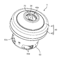
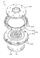
まず、実施の形態に係る電動送風機1の全体の構成について、図1~図4を用いて説明する。図1は、実施の形態に係る電動送風機1の外観斜視図である。図2は、同電動送風機1の分解斜視図である。図3および図4は、同電動送風機1の断面図である。図3は、回転軸13の軸心Cおよびブラシ15を通る平面で切断したときの断面を示している。図4は、切断面を図3から回転軸13の回転方向に90度回転させたときの断面を示している。図3および図4では、断面に表れる線画のみを図示している。
以上、本開示に係る電動送風機について、実施の形態に基づいて説明した。しかし、本開示は、上記実施の形態に限定されるものではない。
10 電動機
11 回転子
11a コア
11b 巻線コイル
12 固定子
13 回転軸
14 整流子
15 ブラシ
16 第1軸受け
17 第2軸受け
20 遠心ファン
20a 吸込口
20b 吹出口
21 第1側板
22 第2側板
23 ファン翼
30 エアガイド
30a 第1面
30b 第2面
30c 第3面
30d 第4面
31 第1エアガイド部
31a 第1仕切り板
31b ディフューザ翼
31c 第1環状凸部
31d 延在翼
31e 貫通孔
32 第2エアガイド部
32a 第2仕切り板
32b 案内翼
32c 第2環状凸部
32d 軸受け保持部
32e ブラシ収納部
33a ディフューザ通風路
33b 戻り通風路
33c 折り返し通風路
40 ファンケース
40a 吸気口
41 蓋部
42 側壁部
50 モータケース
50a 排気口
50b 軸受け保持部
61 締結ナット
62 取付板
70 ファンシール
Claims (6)
- 回転子および前記回転子に取り付けられた回転軸を有する電動機と、
前記回転軸に取り付けられた遠心ファンと、
前記遠心ファンから排出される空気が流入するエアガイドと、を備え、
前記エアガイドは、前記回転軸の軸心方向に分離された第1エアガイド部と第2エアガイド部とを有し、
前記第1エアガイド部は、前記遠心ファンを囲むように前記第2エアガイド部側とは反対側の面に設けられた複数のディフューザ翼を有し、
前記第2エアガイド部は、前記第1エアガイド部側とは反対側の面に設けられた複数の案内翼を有し、
前記第1エアガイド部の外周端は、前記第2エアガイド部の外周端よりも外側に位置し、
前記第1エアガイド部には、前記複数のディフューザ翼のうち隣り合う2つのディフューザ翼で構成されるディフューザ通風路の外周端部の底面から前記第2エアガイド部側に向かって延在する延在翼が設けられている、
電動送風機。 - 前記延在翼は、前記案内翼の外周端部に連結している、
請求項1に記載の電動送風機。 - 前記回転軸の軸心方向から見たときに、前記第2エアガイド部の外形は、前記第2エアガイド部の内側に凹むことなく連続する円弧で構成されている、
請求項1又は2に記載の電動送風機。 - 前記延在翼の内面は、前記第2エアガイド部の外周端に近接している、
請求項1~3のいずれか1項に記載の電動送風機。 - 前記延在翼は、前記案内翼の高さの半分を超える位置まで延在している、
請求項1~4のいずれか1項に記載の電動送風機。 - 前記複数のディフューザ翼の数と前記複数の案内翼の数とが異なる、
請求項1~5のいずれか1項に記載の電動送風機。
Priority Applications (3)
| Application Number | Priority Date | Filing Date | Title |
|---|---|---|---|
| EP22775067.6A EP4317703A1 (en) | 2021-03-24 | 2022-03-08 | Electric blower |
| JP2023508934A JPWO2022202273A1 (ja) | 2021-03-24 | 2022-03-08 | |
| CN202280018820.6A CN116917628A (zh) | 2021-03-24 | 2022-03-08 | 电动风机 |
Applications Claiming Priority (2)
| Application Number | Priority Date | Filing Date | Title |
|---|---|---|---|
| JP2021-049755 | 2021-03-24 | ||
| JP2021049755 | 2021-03-24 |
Publications (1)
| Publication Number | Publication Date |
|---|---|
| WO2022202273A1 true WO2022202273A1 (ja) | 2022-09-29 |
Family
ID=83397057
Family Applications (1)
| Application Number | Title | Priority Date | Filing Date |
|---|---|---|---|
| PCT/JP2022/009907 WO2022202273A1 (ja) | 2021-03-24 | 2022-03-08 | 電動送風機 |
Country Status (4)
| Country | Link |
|---|---|
| EP (1) | EP4317703A1 (ja) |
| JP (1) | JPWO2022202273A1 (ja) |
| CN (1) | CN116917628A (ja) |
| WO (1) | WO2022202273A1 (ja) |
Citations (6)
| Publication number | Priority date | Publication date | Assignee | Title |
|---|---|---|---|---|
| JPH07158593A (ja) * | 1993-12-06 | 1995-06-20 | Hitachi Ltd | 電動送風機 |
| JP2009293434A (ja) * | 2008-06-03 | 2009-12-17 | Toshiba Corp | 電動送風機 |
| WO2012093460A1 (ja) * | 2011-01-05 | 2012-07-12 | パナソニック株式会社 | 電動送風機およびこれを備えた電気掃除機 |
| WO2018003017A1 (ja) * | 2016-06-28 | 2018-01-04 | 三菱電機株式会社 | 電動送風機および電気掃除機 |
| WO2019176625A1 (ja) * | 2018-03-13 | 2019-09-19 | パナソニックIpマネジメント株式会社 | 電動送風機、電気掃除機およびエアタオル |
| JP2020139408A (ja) | 2017-06-26 | 2020-09-03 | パナソニックIpマネジメント株式会社 | 電動送風機及びそれを備える電気掃除機 |
-
2022
- 2022-03-08 CN CN202280018820.6A patent/CN116917628A/zh active Pending
- 2022-03-08 EP EP22775067.6A patent/EP4317703A1/en active Pending
- 2022-03-08 WO PCT/JP2022/009907 patent/WO2022202273A1/ja active Application Filing
- 2022-03-08 JP JP2023508934A patent/JPWO2022202273A1/ja active Pending
Patent Citations (6)
| Publication number | Priority date | Publication date | Assignee | Title |
|---|---|---|---|---|
| JPH07158593A (ja) * | 1993-12-06 | 1995-06-20 | Hitachi Ltd | 電動送風機 |
| JP2009293434A (ja) * | 2008-06-03 | 2009-12-17 | Toshiba Corp | 電動送風機 |
| WO2012093460A1 (ja) * | 2011-01-05 | 2012-07-12 | パナソニック株式会社 | 電動送風機およびこれを備えた電気掃除機 |
| WO2018003017A1 (ja) * | 2016-06-28 | 2018-01-04 | 三菱電機株式会社 | 電動送風機および電気掃除機 |
| JP2020139408A (ja) | 2017-06-26 | 2020-09-03 | パナソニックIpマネジメント株式会社 | 電動送風機及びそれを備える電気掃除機 |
| WO2019176625A1 (ja) * | 2018-03-13 | 2019-09-19 | パナソニックIpマネジメント株式会社 | 電動送風機、電気掃除機およびエアタオル |
Also Published As
| Publication number | Publication date |
|---|---|
| CN116917628A (zh) | 2023-10-20 |
| JPWO2022202273A1 (ja) | 2022-09-29 |
| EP4317703A1 (en) | 2024-02-07 |
Similar Documents
| Publication | Publication Date | Title |
|---|---|---|
| JP7134309B2 (ja) | 電動送風機、電気掃除機および手乾燥装置 | |
| JP6504754B6 (ja) | 電動送風機およびそれを用いた電気掃除機 | |
| WO2016121448A1 (ja) | 電動送風機及びそれを搭載した電気掃除機 | |
| US11268532B2 (en) | Electric blower, electric vacuum cleaner, and hand dryer | |
| KR20160090522A (ko) | 비엘디시 모터 및 그를 갖는 청소기 | |
| JP2015113781A (ja) | 軸流ファンおよび直列型軸流ファン | |
| JP2014042375A (ja) | 電動送風機 | |
| WO2022202273A1 (ja) | 電動送風機 | |
| JP4559812B2 (ja) | 電動送風機 | |
| JPWO2022202273A5 (ja) | ||
| JP2022148165A (ja) | 電動送風機 | |
| JP2019100314A (ja) | 送風装置 | |
| EP3327294A1 (en) | Blower device and cleaner | |
| WO2019176625A1 (ja) | 電動送風機、電気掃除機およびエアタオル | |
| JP6903036B2 (ja) | 電動送風機及びそれを搭載した電気掃除機 | |
| WO2022209344A1 (ja) | 電動送風機及び冷却ファン | |
| JP6788361B2 (ja) | 回転子および電動送風機 | |
| WO2019167152A1 (ja) | モータ、電動送風機、電気掃除機および手乾燥装置 | |
| JP2022062289A (ja) | 電動機及び電動送風機 | |
| WO2023162284A1 (ja) | 電動送風機、および、それを用いた電気掃除機 | |
| JP2021021357A (ja) | ファン及び電動送風機 | |
| JP2010068575A (ja) | 電動送風機 | |
| JPWO2022209344A5 (ja) | ||
| JP2021080909A (ja) | 電動送風機 | |
| WO2020158292A1 (ja) | 電動送風機 |
Legal Events
| Date | Code | Title | Description |
|---|---|---|---|
| 121 | Ep: the epo has been informed by wipo that ep was designated in this application |
Ref document number: 22775067 Country of ref document: EP Kind code of ref document: A1 |
|
| ENP | Entry into the national phase |
Ref document number: 2023508934 Country of ref document: JP Kind code of ref document: A |
|
| WWE | Wipo information: entry into national phase |
Ref document number: 202280018820.6 Country of ref document: CN |
|
| WWE | Wipo information: entry into national phase |
Ref document number: 2022775067 Country of ref document: EP |
|
| NENP | Non-entry into the national phase |
Ref country code: DE |
|
| ENP | Entry into the national phase |
Ref document number: 2022775067 Country of ref document: EP Effective date: 20231024 |