以下、本開示の実施の形態について、図面を参照しながら説明する。なお、以下に説明する実施の形態は、いずれも本開示の一具体例を示すものである。したがって、以下の実施の形態で示される、数値、形状、材料、構成要素、構成要素の配置位置および接続形態等は、一例であって本開示を限定する主旨ではない。よって、以下の実施の形態における構成要素のうち、本開示の最上位概念を示す独立請求項に記載されていない構成要素については、任意の構成要素として説明される。
Hereinafter, embodiments of the present disclosure will be described with reference to the drawings. It should be noted that each of the embodiments described below is a specific example of the present disclosure. Therefore, numerical values, shapes, materials, components, arrangement positions of components, connection forms, and the like shown in the following embodiments are examples and are not intended to limit the present disclosure. Therefore, among the constituent elements in the following embodiments, constituent elements that are not described in independent claims representing the highest concept of the present disclosure will be described as optional constituent elements.
なお、各図は、模式図であり、必ずしも厳密に図示されたものではない。また、各図において、実質的に同一の構成に対しては同一の符号を付しており、重複する説明は省略または簡略化する。
It should be noted that each figure is a schematic diagram and is not necessarily strictly illustrated. Moreover, in each figure, the same code|symbol is attached|subjected to the substantially same structure, and the overlapping description is abbreviate|omitted or simplified.
(実施の形態)
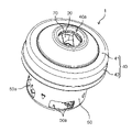
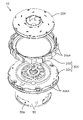
まず、実施の形態に係る電動送風機1の全体の構成について、図1~図4を用いて説明する。図1は、実施の形態に係る電動送風機1の外観斜視図である。図2は、同電動送風機1の分解斜視図である。図3および図4は、同電動送風機1の断面図である。図3は、回転軸13の軸心Cおよびブラシ15を通る平面で切断したときの断面を示している。図4は、切断面を図3から回転軸13の回転方向に90度回転させたときの断面を示している。図3および図4では、断面に表れる線画のみを図示している。
(Embodiment)
First, the overall configuration of an electric blower 1 according to an embodiment will be described with reference to FIGS. 1 to 4. FIG. FIG. 1 is an external perspective view of an electric blower 1 according to an embodiment. FIG. 2 is an exploded perspective view of the electric blower 1. FIG. 3 and 4 are sectional views of the electric blower 1. FIG. FIG. 3 shows a cross section taken along a plane passing through the axis C of the rotating shaft 13 and the brush 15. As shown in FIG. FIG. 4 shows a cross section when the cut plane is rotated 90 degrees in the direction of rotation of the rotating shaft 13 from FIG. In FIGS. 3 and 4, only line drawings appearing in the cross section are illustrated.
さらに、後述する説明において、便宜上、回転軸13の軸心Cが延伸する方向を上下方向としている。具体的には、図3中、軸心Cが延伸する方向において、回転子11から遠心ファン20が位置する出力軸側を上側とし、回転子11から第2軸受け17が位置する反出力軸側を下側としている。この上下方向は、以下の説明を分かり易くするために便宜上定めたものである。よって、この上下方向は、電動送風機1の使用状態などによって現実の上下方向とは異なる場合がある。
Furthermore, in the description that follows, for convenience, the direction in which the axis C of the rotating shaft 13 extends is referred to as the vertical direction. Specifically, in FIG. 3, in the direction in which the axial center C extends, the output shaft side where the centrifugal fan 20 is positioned from the rotor 11 is the upper side, and the counter-output shaft side where the second bearing 17 is positioned from the rotor 11. is on the bottom side. This vertical direction is defined for convenience in order to facilitate understanding of the following description. Therefore, this vertical direction may differ from the actual vertical direction depending on the usage condition of the electric blower 1 or the like.
図1~図4に示すように、本実施の形態における電動送風機1は、電動機10と、遠心ファン20と、エアガイド30と、ファンケース40と、モータケース50とを備える。電動機10は、回転子11および固定子12を有する。遠心ファン20は、電動機10が有する回転軸13に取り付けられている。エアガイド30は、遠心ファン20から排出された空気が流れ込む。ファンケース40は、遠心ファン20およびエアガイド30を覆う。モータケース50は、電動機10を収納する。
As shown in FIGS. 1 to 4, the electric blower 1 in this embodiment includes an electric motor 10, a centrifugal fan 20, an air guide 30, a fan case 40, and a motor case 50. Electric motor 10 has rotor 11 and stator 12 . Centrifugal fan 20 is attached to rotating shaft 13 of electric motor 10 . Air discharged from the centrifugal fan 20 flows into the air guide 30 . Fan case 40 covers centrifugal fan 20 and air guide 30 . Motor case 50 accommodates electric motor 10 .
電動機10は、遠心ファン20を回転させるモータである。電動機10は、ブラシ付き整流子電動機である。電動機10は、回転子11と、固定子12と、回転軸13と、整流子14と、ブラシ15と、第1軸受け16と、第2軸受け17とを備える。
The electric motor 10 is a motor that rotates the centrifugal fan 20. Motor 10 is a brushed commutator motor. Electric motor 10 includes rotor 11 , stator 12 , rotating shaft 13 , commutator 14 , brushes 15 , first bearing 16 and second bearing 17 .
回転子11(ロータ)は、回転軸13を有する。回転子11は、固定子12による磁力によって回転軸13を回転中心として回転する。回転子11は、インナーロータである。回転子11は、図3および図4に示すように、固定子12の内側に配置されている。具体的には、回転子11は、固定子12との間に微小なエアギャップを介して固定子12に囲まれている。
The rotor 11 (rotor) has a rotating shaft 13 . The rotor 11 rotates about the rotating shaft 13 by the magnetic force of the stator 12 . The rotor 11 is an inner rotor. The rotor 11 is arranged inside the stator 12 as shown in FIGS. Specifically, the rotor 11 is surrounded by the stator 12 with a small air gap therebetween.
本実施の形態において、回転子11は、電機子である。回転子11は、コア11a(回転子鉄心)と、コア11aに巻回された巻線コイル11bとを有する。なお、図3および図4において、巻線コイル11bは、模式的に示している。コア11aは、磁性材料によって構成された磁性体である。一例として、コア11aは、複数の電磁鋼板が回転軸13の軸心Cが延伸する方向(軸心方向)に積層された積層体である。コア11aは、径方向に突出する複数のティース部を有している。巻線コイル11bに電流が流れることで、各ティース部は、固定子12に作用させる磁力を発生させる。
In this embodiment, the rotor 11 is an armature. The rotor 11 has a core 11a (rotor core) and winding coils 11b wound around the core 11a. In addition, in FIG.3 and FIG.4, the winding coil 11b is shown typically. The core 11a is a magnetic body made of a magnetic material. As an example, the core 11a is a laminate in which a plurality of electromagnetic steel sheets are laminated in the direction (axial direction) in which the axial center C of the rotating shaft 13 extends. The core 11a has a plurality of radially projecting teeth. Each tooth generates a magnetic force that acts on the stator 12 by the current flowing through the winding coil 11b.
固定子12(ステータ)は、回転子11と向い合って位置している。固定子12は、回転子11に作用する磁力を発生させる。固定子12は、回転子11を囲むように配置されている。固定子12は、エアギャップ面にN極とS極とが周方向に交互に表れるように構成されている。この場合、固定子12は、コアとコアに巻回された巻線コイルとによって構成された電機子であってもよい。固定子12は、周方向に沿って配置された複数の永久磁石によって構成されていてもよい。なお、固定子12は、モータケース50に固定されている。
The stator 12 (stator) is positioned facing the rotor 11 . The stator 12 generates magnetic force acting on the rotor 11 . Stator 12 is arranged to surround rotor 11 . The stator 12 is configured such that N poles and S poles appear alternately in the circumferential direction on the air gap surface. In this case, the stator 12 may be an armature composed of a core and winding coils wound around the core. The stator 12 may be composed of a plurality of permanent magnets arranged along the circumferential direction. Note that the stator 12 is fixed to the motor case 50 .
回転軸13は、回転子11が回転する際の中心となるシャフトである。回転軸13は、軸心C方向である長手方向に延伸している。回転軸13は、例えば金属棒である。回転軸13は、回転子11に固定されている。具体的には、回転軸13は、例えば、回転子11の両側に延在するように回転子11のコア11aの中心を貫いた状態でコア11aに固定されている。一例として、回転軸13は、コア11aに設けられた中心孔に圧入したり焼き嵌めしたりすることでコア11aに固定されている。
The rotating shaft 13 is a shaft that serves as the center when the rotor 11 rotates. The rotating shaft 13 extends in the longitudinal direction, which is the axial center C direction. The rotating shaft 13 is, for example, a metal rod. The rotating shaft 13 is fixed to the rotor 11 . Specifically, the rotating shaft 13 is fixed to the core 11 a of the rotor 11 while penetrating the center of the core 11 a of the rotor 11 so as to extend on both sides of the rotor 11 . As an example, the rotating shaft 13 is fixed to the core 11a by press-fitting or shrink-fitting into a center hole provided in the core 11a.
回転軸13が有する一方の端部(遠心ファン20側の端部)は、第1軸受け16に支持されている。一方、回転軸13が有する他方の端部は、第2軸受け17に支持されている。一例として、第1軸受け16および第2軸受け17は、回転軸13を支持する玉軸受である。このように、回転軸13は、第1軸受け16と第2軸受け17とによって、回転自在となるように両端部が保持されている。回転軸13の一方の端部は、第1軸受け16から突出している。回転軸13の先端部には、遠心ファン20が取り付けられている。
One end of the rotating shaft 13 (the end on the centrifugal fan 20 side) is supported by the first bearing 16 . On the other hand, the other end of rotating shaft 13 is supported by a second bearing 17 . As an example, the first bearing 16 and the second bearing 17 are ball bearings that support the rotating shaft 13 . Thus, both ends of the rotating shaft 13 are held by the first bearing 16 and the second bearing 17 so as to be rotatable. One end of the rotating shaft 13 protrudes from the first bearing 16 . A centrifugal fan 20 is attached to the tip of the rotating shaft 13 .
整流子14は、回転軸13に取り付けられている。整流子14は、回転軸13における回転子11と第2軸受け17との間の部分に固定されている。整流子14は、回転子11が有する巻線コイル11bと電気的に接続されている。整流子14は、ブラシ15と摺接する。整流子14は、回転軸13の回転方向に互いに絶縁分離された複数の整流子片を有する。
The commutator 14 is attached to the rotating shaft 13 . The commutator 14 is fixed to a portion of the rotating shaft 13 between the rotor 11 and the second bearing 17 . Commutator 14 is electrically connected to winding coils 11 b of rotor 11 . The commutator 14 is in sliding contact with the brushes 15 . The commutator 14 has a plurality of commutator segments that are insulated and separated from each other in the rotating direction of the rotating shaft 13 .
ブラシ15は、整流子14に接触することで回転子11に電力を供給するための給電ブラシである。具体的には、ブラシ15は、整流子14の整流子片に接触することで整流子14に電機子電流を供給する。一例として、ブラシ15は、カーボンブラシである。また、ブラシ15は、長尺状の実質的な直方体である。
The brushes 15 are power supply brushes for supplying power to the rotor 11 by contacting the commutator 14 . Specifically, the brushes 15 supply the armature current to the commutator 14 by contacting the commutator bars of the commutator 14 . As an example, the brush 15 is a carbon brush. Moreover, the brush 15 is an elongated substantially rectangular parallelepiped.
ブラシ15は、整流子14に摺接可能に配置されている。本実施の形態において、ブラシ15は、一対設けられている。一対のブラシ15は、整流子14を挟持するように整流子14を挟んで対向して配置されている。具体的には、一対のブラシ15の各々の内側の先端部は、整流子14に当接している。
The brush 15 is arranged so as to be slidably contactable with the commutator 14 . In this embodiment, a pair of brushes 15 are provided. A pair of brushes 15 are arranged to face each other with the commutator 14 interposed therebetween. Specifically, the inner tip of each of the pair of brushes 15 is in contact with the commutator 14 .
遠心ファン20は、ファンケース40とモータケース50とにより構成される外郭筐体(ハウジング)の内部に空気を吸引する。
The centrifugal fan 20 sucks air into an outer casing (housing) composed of the fan case 40 and the motor case 50 .
遠心ファン20は、電動機10が有する回転軸13の所定の部位に取り付けられている。遠心ファン20は、回転軸13が回転することで回転する。本実施の形態において、遠心ファン20は、回転軸13の先端部に取り付けられている。遠心ファン20は、例えば、締結ナット61および複数の取付板62とともに回転軸13に挿入される。遠心ファン20は、締結ナット61を締め付けることで回転軸13に加圧保持されている。遠心ファン20と回転軸13との固定方法は、これに限るものではない。
The centrifugal fan 20 is attached to a predetermined portion of the rotating shaft 13 of the electric motor 10 . Centrifugal fan 20 rotates as rotating shaft 13 rotates. In the present embodiment, centrifugal fan 20 is attached to the tip of rotating shaft 13 . The centrifugal fan 20 is inserted into the rotary shaft 13 together with, for example, a fastening nut 61 and a plurality of mounting plates 62 . The centrifugal fan 20 is pressurized and held on the rotary shaft 13 by tightening the fastening nut 61 . The method of fixing the centrifugal fan 20 and the rotating shaft 13 is not limited to this.
遠心ファン20は、空気を吸い込むための吸込口20a(吸気口)と、吸込口20aから吸い込んだ空気を吹き出す吹出口20b(排気口)とを有する。遠心ファン20は、吸込口20aが設けられた第1側板21と、第1側板21と所定の間隙を隔てて第1側板21に対面する第2側板22と、第1側板21および第2側板22に挟持された複数のファン翼23とを有する。遠心ファン20の吸込口20aは、円形の開口であり、遠心ファン20の中央部に設けられている。複数のファン翼23は、各々が円弧状に湾曲する板状部材である。複数のファン翼23は、放射状に配置されている。複数のファン翼23は、等間隔で渦巻き状となるように配置されている。隣り合う2つのファン翼23と第1側板21と第2側板22とで囲まれる空間は、吸込口20aから遠心ファン20内に流入した空気が通る通風路である。この通風路の径方向外側の開口が吹出口20bになっている。第1側板21、第2側板22およびファン翼23は、例えばアルミニウム板などの金属板によって構成されている。しかし、これに限らない。
The centrifugal fan 20 has an intake port 20a (intake port) for sucking air and a blowout port 20b (exhaust port) for blowing out the air sucked from the suction port 20a. The centrifugal fan 20 includes a first side plate 21 provided with a suction port 20a, a second side plate 22 facing the first side plate 21 with a predetermined gap from the first side plate 21, and the first side plate 21 and the second side plate. 22 and a plurality of fan blades 23 sandwiched between them. The suction port 20 a of the centrifugal fan 20 is a circular opening provided in the central portion of the centrifugal fan 20 . Each of the plurality of fan blades 23 is a plate-like member curved in an arc shape. A plurality of fan blades 23 are arranged radially. The plurality of fan blades 23 are arranged in a spiral shape at regular intervals. A space surrounded by the two adjacent fan blades 23, the first side plate 21, and the second side plate 22 is a ventilation passage through which air flows into the centrifugal fan 20 from the suction port 20a. A radially outer opening of the air passage serves as the outlet 20b. The first side plate 21, the second side plate 22 and the fan blades 23 are made of a metal plate such as an aluminum plate. However, it is not limited to this.
遠心ファン20が回転することにより風圧が発生し、ファンケース40の吸気口40aから空気が吸い込まれる。具体的には、遠心ファン20が回転すると、遠心ファン20の吹出口20b付近が高圧になって吸引圧力が発生する。ファンケース40の吸気口40aから外部の空気が吸い込まれる。ファンケース40内に吸い込まれた空気は、遠心ファン20の吸込口20aから吸い込まれて吹出口20bから吹き出され、エアガイド30に流れ込む。つまり、エアガイド30には、遠心ファン20から排出された空気が流入する。
Wind pressure is generated by the rotation of the centrifugal fan 20, and air is sucked from the air intake port 40a of the fan case 40. Specifically, when the centrifugal fan 20 rotates, the vicinity of the outlet 20b of the centrifugal fan 20 becomes high pressure and suction pressure is generated. External air is sucked from the intake port 40 a of the fan case 40 . The air sucked into the fan case 40 is sucked from the suction port 20a of the centrifugal fan 20, blown out from the blowout port 20b, and flows into the air guide 30. - 特許庁That is, air discharged from the centrifugal fan 20 flows into the air guide 30 .
エアガイド30は、遠心ファン20から排出された空気の流れを整流してモータケース50へと流し込む。エアガイド30は、回転軸13の軸心C方向において、遠心ファン20と回転子11との間に配置されている。
The air guide 30 rectifies the flow of air discharged from the centrifugal fan 20 and flows it into the motor case 50 . The air guide 30 is arranged between the centrifugal fan 20 and the rotor 11 in the axial center C direction of the rotating shaft 13 .
本実施の形態において、エアガイド30は、複数に分離されている。具体的には、エアガイド30は、回転軸13の軸心C方向に2つに分離されている。2つに分離されたエアガイド30は、回転軸13の軸心C方向から挟み込まれるように押さえ付けられて結合されている。なお、エアガイド30の詳細な構成については、後述する。
In the present embodiment, the air guide 30 is divided into multiple pieces. Specifically, the air guide 30 is separated into two in the axial center C direction of the rotary shaft 13 . The two separated air guides 30 are joined together while being pressed so as to be sandwiched from the axial center C direction of the rotating shaft 13 . A detailed configuration of the air guide 30 will be described later.
エアガイド30は、第1軸受け16を保持するブラケットとしても機能する。したがって、エアガイド30には、第1軸受け16を保持する軸受け保持部32dが設けられている。エアガイド30は、ブラシ15を保持するブラシホルダとしても機能する。したがって、エアガイド30には、ブラシ15を保持するブラシ収納部32eを有する。
The air guide 30 also functions as a bracket that holds the first bearing 16. Therefore, the air guide 30 is provided with a bearing holding portion 32 d that holds the first bearing 16 . The air guide 30 also functions as a brush holder that holds the brush 15 . Therefore, the air guide 30 has a brush housing portion 32e for holding the brush 15. As shown in FIG.
ファンケース40は、遠心ファン20およびエアガイド30を覆うカバーである。具体的には、ファンケース40は、金属材料によって構成された金属カバーである。ファンケース40は、遠心ファン20およびエアガイド30の上方部分を覆う蓋部41(第1ファンケース部)と、遠心ファン20およびエアガイド30の側方部分を覆う側壁部42(第2ファンケース部)とを有する。
The fan case 40 is a cover that covers the centrifugal fan 20 and the air guide 30. Specifically, the fan case 40 is a metal cover made of a metal material. The fan case 40 includes a cover portion 41 (first fan case portion) that covers the upper portion of the centrifugal fan 20 and the air guide 30, and a side wall portion 42 (second fan case portion) that covers the side portions of the centrifugal fan 20 and the air guide 30. part).
ファンケース40は、モータケース50に固定されている。具体的には、ファンケース40の側壁部42とモータケース50の筒部とが接続されることで、ファンケース40とモータケース50とが固定されている。具体的には、ファンケース40の側壁部42の下端部とモータケース50の筒部の上端部とが重なり合うように圧入されてファンケース40とモータケース50とが互いに固定されている。
The fan case 40 is fixed to the motor case 50. Specifically, the fan case 40 and the motor case 50 are fixed by connecting the side wall portion 42 of the fan case 40 and the cylindrical portion of the motor case 50 . Specifically, the fan case 40 and the motor case 50 are fixed to each other by press-fitting so that the lower end of the side wall 42 of the fan case 40 and the upper end of the cylindrical portion of the motor case 50 overlap.
ファンケース40は、外気を吸引するための吸気口40a(吸込口)を有している。吸気口40aは、蓋部41の中央部に設けられた円形の貫通孔である。ファンケース40の吸気口40aは、遠心ファン20の吸込口20aに対向している。遠心ファン20が回転することで、ファンケース40の吸気口40aからファンケース40内に空気が流れ込む。
The fan case 40 has an intake port 40a (intake port) for sucking outside air. The intake port 40 a is a circular through hole provided in the central portion of the lid portion 41 . An intake port 40 a of the fan case 40 faces the intake port 20 a of the centrifugal fan 20 . As the centrifugal fan 20 rotates, air flows into the fan case 40 from the air inlet 40 a of the fan case 40 .
ファンケース40には、ファンシール70が取り付けられている。ファンシール70は、ファンケース40の吸気口40aを囲うようにファンケース40の蓋部41に取り付けられている。ファンシール70は、遠心ファン20の吸込口20aの開口端とファンケース40の吸気口40aの開口端との間に形成される円環状の隙間を塞いでいる。これにより、ファンシール70を設けない場合と比べて、電動送風機1の送風効率を向上させることができる。つまり、遠心ファン20が回転すると遠心ファン20の吹出口20b付近が高圧になるので、ファンシール70を設けない場合は、遠心ファン20の第1側板21とファンケース40の蓋部41との間の空間路に風圧差が生じて遠心ファン20の吹出口20bからファンケース40の吸気口40aに向かう循環流が発生する。しかし、ファンシール70を設けることで、このような循環流を低減して圧力が逃げないようにすることができる。したがって、電動送風機1の送風効率を向上させることができる。
A fan seal 70 is attached to the fan case 40 . The fan seal 70 is attached to the lid portion 41 of the fan case 40 so as to surround the air inlet 40 a of the fan case 40 . The fan seal 70 closes an annular gap formed between the opening end of the suction port 20 a of the centrifugal fan 20 and the opening end of the suction port 40 a of the fan case 40 . As a result, compared to the case where the fan seal 70 is not provided, the blowing efficiency of the electric blower 1 can be improved. That is, when the centrifugal fan 20 rotates, the vicinity of the outlet 20b of the centrifugal fan 20 becomes high pressure. A wind pressure difference is generated in the space path of the centrifugal fan 20 to generate a circulation flow from the air outlet 20b of the centrifugal fan 20 to the air inlet 40a of the fan case 40 . However, by providing the fan seal 70, such circulation flow can be reduced to prevent the pressure from escaping. Therefore, the blowing efficiency of the electric blower 1 can be improved.
モータケース50は、電動機10を収納する筐体(フレーム)である。具体的には、モータケース50は、回転子11および固定子12を収納する。つまり、モータケース50は、内部に回転子11および固定子12を有している。モータケース50は、例えば、金属材料によって構成された金属ケースである。
The motor case 50 is a housing (frame) that houses the electric motor 10 . Specifically, motor case 50 accommodates rotor 11 and stator 12 . That is, the motor case 50 has the rotor 11 and the stator 12 inside. The motor case 50 is, for example, a metal case made of a metal material.
モータケース50は、開口部を有する有底円筒形状である。モータケース50は、底部および円筒状の側壁を有する。モータケース50の底部および側壁には、遠心ファン20の回転によって吸い込んだ空気を吹き出すための複数の排気口50a(吹出口)が設けられている。つまり、排気口50aは、遠心ファン20によってモータケース50に吸引された空気を排気する貫通孔である。
The motor case 50 has a bottomed cylindrical shape with an opening. Motor case 50 has a bottom and a cylindrical side wall. The bottom and side walls of the motor case 50 are provided with a plurality of exhaust ports 50a (blow-out ports) for blowing out the air sucked by the rotation of the centrifugal fan 20 . That is, the exhaust port 50 a is a through hole through which the air sucked into the motor case 50 by the centrifugal fan 20 is exhausted.
モータケース50は、第2軸受け17を保持するブラケットとしても機能する。したがって、モータケース50には、第2軸受け17を保持する軸受け保持部50bを有する。軸受け保持部50bは、モータケース50の底部に設けられている。
The motor case 50 also functions as a bracket that holds the second bearing 17. Therefore, the motor case 50 has a bearing holding portion 50 b that holds the second bearing 17 . The bearing holding portion 50b is provided at the bottom of the motor case 50. As shown in FIG.
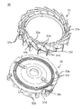
次に、本実施の形態に係る電動送風機1に用いられるエアガイド30の詳細な構成について、図3および図4を参照しながら、図5~図9Cを用いて説明する。図5は、実施の形態に係る電動送風機1に用いられるエアガイド30を斜め上方から見たときの分解斜視図である。図6は、同エアガイド30を斜め下方から見たときの分解斜視図である。図7は、ファンケース40を外した状態における同電動送風機1の斜視図である。図8は、図7に示す電動送風機の分解斜視図である。図9Aは、同電動送風機1における遠心ファン20およびエアガイド30の構成を示す斜視図である。図9Bは、同電動送風機1における遠心ファン20およびエアガイド30の構成を示す上面図である。図9Cは、同電動送風機1における遠心ファン20およびエアガイド30の構成を示す背面図である。図9Cに示す背面図にのみ、ファンケース40を示す。
Next, the detailed configuration of the air guide 30 used in the electric blower 1 according to the present embodiment will be described with reference to FIGS. 5 to 9C while referring to FIGS. 3 and 4. FIG. FIG. 5 is an exploded perspective view of the air guide 30 used in the electric blower 1 according to the embodiment when viewed obliquely from above. FIG. 6 is an exploded perspective view of the air guide 30 as seen obliquely from below. FIG. 7 is a perspective view of the electric blower 1 with the fan case 40 removed. 8 is an exploded perspective view of the electric blower shown in FIG. 7. FIG. 9A is a perspective view showing the configuration of the centrifugal fan 20 and the air guide 30 in the electric blower 1. FIG. 9B is a top view showing the configuration of the centrifugal fan 20 and the air guide 30 in the electric blower 1. FIG. 9C is a rear view showing the configuration of the centrifugal fan 20 and the air guide 30 in the electric blower 1. FIG. Fan case 40 is shown only in the rear view shown in FIG. 9C.
上記のように、エアガイド30は、回転軸13の軸心C方向において2つに分離されている。具体的には、図3および図4に示すように、エアガイド30は、回転軸13の軸心C方向に第1エアガイド部31と第2エアガイド部32とに分離されている。つまり、エアガイド30は、第1部材である第1エアガイド部31と第2部材である第2エアガイド部32との2つの部品を有する。
As described above, the air guide 30 is separated into two in the axial center C direction of the rotating shaft 13 . Specifically, as shown in FIGS. 3 and 4 , the air guide 30 is separated into a first air guide portion 31 and a second air guide portion 32 in the axial center C direction of the rotating shaft 13 . That is, the air guide 30 has two parts, a first air guide portion 31 as a first member and a second air guide portion 32 as a second member.
分離された第1エアガイド部31と第2エアガイド部32とは、連結されて保持されている。具体的には、第2エアガイド部32がネジによってモータケース50に固定されており、ファンケース40によって上から第1エアガイド部31を第2エアガイド部32に押し付けることで、第1エアガイド部31と第2エアガイド部32とが連結されて固定されている。
The separated first air guide portion 31 and second air guide portion 32 are connected and held. Specifically, the second air guide portion 32 is fixed to the motor case 50 with screws, and the fan case 40 presses the first air guide portion 31 against the second air guide portion 32 from above, thereby The guide portion 31 and the second air guide portion 32 are connected and fixed.
第1エアガイド部31は、第2エアガイド部32側とは反対側(遠心ファン20側)の面である第1面30a(本実施の形態では第1エアガイド部31の上面)と、第2エアガイド部32側(回転子11側)の面である第2面30b(本実施の形態では第1エアガイド部31の下面)とを有する。
The first air guide portion 31 includes a first surface 30a (the upper surface of the first air guide portion 31 in the present embodiment), which is the surface opposite to the second air guide portion 32 (centrifugal fan 20 side), and a second surface 30b (the lower surface of the first air guide portion 31 in the present embodiment) that faces the second air guide portion 32 (rotor 11 side).
また、第2エアガイド部32は、第1エアガイド部31側(遠心ファン20側)の面である第3面30c(本実施の形態では第2エアガイド部32の上面)と、第1エアガイド部31側とは反対側の面(回転子11側)である第4面30d(本実施の形態では第2エアガイド部32の下面)とを有する。
In addition, the second air guide portion 32 includes a third surface 30c (the upper surface of the second air guide portion 32 in the present embodiment), which is a surface on the side of the first air guide portion 31 (the side of the centrifugal fan 20), and a first and a fourth surface 30d (the lower surface of the second air guide portion 32 in the present embodiment) that is the surface (rotor 11 side) opposite to the air guide portion 31 side.
第1エアガイド部31と第2エアガイド部32とは、回転軸13の軸心C方向に合わせ面を有するように結合されている。具体的には、第1エアガイド部31と第2エアガイド部32とは、第1エアガイド部31の第2面30bと第2エアガイド部32の第3面30cとが対面するように結合されている。
The first air guide portion 31 and the second air guide portion 32 are connected so as to have mating surfaces in the axial center C direction of the rotating shaft 13 . Specifically, the first air guide portion 31 and the second air guide portion 32 are arranged such that the second surface 30b of the first air guide portion 31 and the third surface 30c of the second air guide portion 32 face each other. Combined.
第1エアガイド部31および第2エアガイド部32は、いずれも樹脂材料によって構成されている。第1エアガイド部31は、ポリブチレンテレフタレート(Polybutylene Terephthalate,PBT)または6ナイロン等からなる熱可塑性樹脂によって構成されている。一方、第2エアガイド部32は、電動機10側の部材であって耐熱性が要求されることから、不飽和ポリエステル樹脂(Bulk Molding Compound,BMC)等の硬化性樹脂によって構成されている。硬化性樹脂としては、熱硬化性樹脂または紫外線硬化性樹脂を用いることができる。なお、第1エアガイド部31および第2エアガイド部32は、異なる樹脂材料ではなく、同じ樹脂材料によって構成されていてもよい。
Both the first air guide portion 31 and the second air guide portion 32 are made of a resin material. The first air guide portion 31 is made of thermoplastic resin such as polybutylene terephthalate (PBT) or 6-nylon. On the other hand, the second air guide portion 32 is a member on the electric motor 10 side and is required to have heat resistance, so it is made of a curable resin such as an unsaturated polyester resin (Bulk Molding Compound, BMC). A thermosetting resin or an ultraviolet curable resin can be used as the curable resin. The first air guide portion 31 and the second air guide portion 32 may be made of the same resin material instead of different resin materials.
図5および図6に示すように、第1エアガイド部31は、全体として略円環状に形成されている。図7~図9Cに示すように、円環状の第1エアガイド部31は、遠心ファン20を囲むように配置される。本実施の形態において、第1エアガイド部31の中央開口部の内周端部は、遠心ファン20の外周端部に近接している。
As shown in FIGS. 5 and 6, the first air guide portion 31 is formed in a generally annular shape as a whole. As shown in FIGS. 7 to 9C, the annular first air guide portion 31 is arranged to surround the centrifugal fan 20. As shown in FIGS. In the present embodiment, the inner peripheral edge of the central opening of the first air guide portion 31 is close to the outer peripheral edge of the centrifugal fan 20 .
図5および図6に示すように、第1エアガイド部31は、第1仕切り板31aと、第1仕切り板31aに設けられた複数のディフューザ翼31bと、第1仕切り板31aに設けられた第1環状凸部31cと、第1仕切り板31aに設けられた延在翼31dとを有する。
As shown in FIGS. 5 and 6, the first air guide portion 31 includes a first partition plate 31a, a plurality of diffuser blades 31b provided on the first partition plate 31a, and a It has a first annular protrusion 31c and an extension wing 31d provided on the first partition plate 31a.
第1仕切り板31aは、実質的に環状で板状のベース部である。第1仕切り板31aの上面は、第1エアガイド部31の第1面30aである。第1仕切り板31aの下面は、第1エアガイド部31の第2面30bである。
The first partition plate 31a is a substantially annular plate-shaped base portion. The upper surface of the first partition plate 31 a is the first surface 30 a of the first air guide portion 31 . The lower surface of the first partition plate 31 a is the second surface 30 b of the first air guide portion 31 .
複数のディフューザ翼31bは、第1仕切り板31aの上面に設けられている。つまり、複数のディフューザ翼31bは、第1エアガイド部31の第1面30aに設けられている。図7~図9Cに示すように、複数のディフューザ翼31bは、遠心ファン20を囲むように設けられている。具体的には、複数のディフューザ翼31bは、遠心ファン20の側方を囲むように設けられている。
A plurality of diffuser blades 31b are provided on the upper surface of the first partition plate 31a. That is, the plurality of diffuser blades 31b are provided on the first surface 30a of the first air guide portion 31. As shown in FIG. As shown in FIGS. 7 to 9C, a plurality of diffuser blades 31b are provided so as to surround centrifugal fan 20. As shown in FIGS. Specifically, the plurality of diffuser blades 31b are provided so as to surround the sides of the centrifugal fan 20 .
図5および図6に示すように、複数のディフューザ翼31bは、各々が円弧状に湾曲する板形状である。複数のディフューザ翼31bは、第1仕切り板31aの上面(第1面30a)に立設している。複数のディフューザ翼31bは、回転軸13の軸心Cを中心にして、渦巻き状に配置されている。本実施の形態において、ディフューザ翼31bは、18枚設けられている。しかし、ディフューザ翼31bの枚数は、18枚に限るものではない。
As shown in FIGS. 5 and 6, each of the plurality of diffuser blades 31b has a plate shape curved in an arc. A plurality of diffuser blades 31b are erected on the upper surface (first surface 30a) of the first partition plate 31a. The plurality of diffuser blades 31b are spirally arranged around the axis C of the rotating shaft 13 . In this embodiment, 18 diffuser blades 31b are provided. However, the number of diffuser blades 31b is not limited to eighteen.
図4および図5に示すように、第1エアガイド部31では、複数のディフューザ翼31bによって複数のディフューザ通風路33a(第1通風路)が形成されている。複数のディフューザ通風路33aの各々は、隣り合う2つのディフューザ翼31bと第1仕切り板31aとファンケース40の蓋部41とで囲まれる空気流路である。つまり、各ディフューザ通風路33aは、2つのディフューザ翼31bの内面を一対の側面とし、第1仕切り板31aの上面(第1面30a)を底面とし、ファンケース40の蓋部41の内面を上面とする空間領域である。
As shown in FIGS. 4 and 5, in the first air guide portion 31, a plurality of diffuser blades 31b form a plurality of diffuser air passages 33a (first air passages). Each of the plurality of diffuser air passages 33a is an air passage surrounded by two adjacent diffuser blades 31b, the first partition plate 31a, and the lid portion 41 of the fan case 40. As shown in FIG. That is, each diffuser air passage 33a has a pair of side surfaces formed by the inner surfaces of the two diffuser blades 31b, a bottom surface formed by the upper surface (first surface 30a) of the first partition plate 31a, and an inner surface of the lid portion 41 of the fan case 40 formed on the upper surface. is a spatial domain where
ディフューザ通風路33aは、遠心ファン20の回転により昇圧された空気の流れの速度を徐々に下げて圧力を回復させる機能を有する。このため、ディフューザ通風路33aは、第1エアガイド部31の内側から外側に向かって、ディフューザ通風路33aの断面積が徐々に拡大するように構成されている。具体的には、遠心ファン20から排出された空気が入り込むディフューザ通風路33aの入り口側から第1エアガイド部31の外方であるディフューザ通風路33aの出口側に向かって、隣り合う2つのディフューザ翼31bの間隔が徐々に広くなっている。
The diffuser air passage 33a has the function of gradually reducing the speed of the flow of air pressurized by the rotation of the centrifugal fan 20 to recover the pressure. Therefore, the diffuser ventilation passage 33a is configured such that the cross-sectional area of the diffuser ventilation passage 33a gradually expands from the inside to the outside of the first air guide portion 31 . Specifically, from the entrance side of the diffuser ventilation passage 33a into which the air discharged from the centrifugal fan 20 enters, toward the exit side of the diffuser ventilation passage 33a outside the first air guide portion 31, two adjacent diffusers are arranged. The interval between the blades 31b is gradually widened.
なお、第1エアガイド部31におけるディフューザ通風路33aの出口部分に、貫通孔31eが設けられている。これにより、ディフューザ通風路33aに流れる空気の流れを乱すことなく、貫通孔31eを通過する風を生成することができる。したがって、電動送風機1の送風性能を低下させることなく電動送風機1の騒音を抑制することができる。貫通孔31eは、複数のディフューザ通風路33aの各々に複数ずつ設けられている。具体的には、各ディフューザ通風路33aには、φ1mm程度の2つの貫通孔31eが設けられている。
A through-hole 31e is provided in the first air guide portion 31 at the exit portion of the diffuser ventilation passage 33a. As a result, it is possible to generate wind that passes through the through holes 31e without disturbing the flow of air that flows through the diffuser ventilation passage 33a. Therefore, the noise of the electric blower 1 can be suppressed without lowering the blowing performance of the electric blower 1 . A plurality of through holes 31e are provided in each of the plurality of diffuser ventilation passages 33a. Specifically, each diffuser ventilation passage 33a is provided with two through holes 31e of about φ1 mm.
図6に示すように、第1エアガイド部31の第1環状凸部31cは、第1仕切り板31aの下面に設けられている。つまり、第1環状凸部31cは、第1エアガイド部31の第2面30bに設けられている。第1環状凸部31cは、第1仕切り板31aの下面(第2面30b)から突出するように形成された突条の突起(環状壁)である。第1環状凸部31cは、回転軸13を基準として、遠心ファン20の外側端部近傍に設けられている。つまり、エアガイド30を回転軸13の軸心C方向に沿って上方から見たときに、第1環状凸部31cは、遠心ファン20の外側端部近傍に設けられている。具体的には、第1環状凸部31cは、第1エアガイド部31の径方向外側寄りに形成されている。
As shown in FIG. 6, the first annular convex portion 31c of the first air guide portion 31 is provided on the lower surface of the first partition plate 31a. That is, the first annular projection 31 c is provided on the second surface 30 b of the first air guide portion 31 . The first annular projection 31c is a protrusion (annular wall) formed to protrude from the lower surface (second surface 30b) of the first partition plate 31a. The first annular protrusion 31c is provided near the outer end of the centrifugal fan 20 with the rotating shaft 13 as a reference. That is, when the air guide 30 is viewed from above along the direction of the axis C of the rotating shaft 13, the first annular protrusion 31c is provided near the outer end of the centrifugal fan 20. As shown in FIG. Specifically, the first annular convex portion 31c is formed radially outward of the first air guide portion 31 .
第1環状凸部31cは、二重の円形環状である。二重の円形環状である第1環状凸部31cによって円形の環状溝が形成される。つまり、第1環状凸部31cは、同心円状に形成された一対の円環状の突起である。
The first annular projection 31c has a double circular annular shape. A circular annular groove is formed by the first annular convex portion 31c which is a double circular annular shape. That is, the first annular protrusion 31c is a pair of annular projections formed concentrically.
図5および図6に示すように、第2エアガイド部32は、第2仕切り板32aと、第2仕切り板32aに設けられた複数の案内翼32b(案内羽根)と、第2仕切り板32aに設けられた第2環状凸部32cとを有する。第2エアガイド部32は、さらに、第1軸受け16を保持する軸受け保持部32dと、ブラシ15を保持するブラシ収納部32eとを有する。
As shown in FIGS. 5 and 6, the second air guide portion 32 includes a second partition plate 32a, a plurality of guide vanes 32b (guide vanes) provided on the second partition plate 32a, and the second partition plate 32a. and a second annular projection 32c provided on the . The second air guide portion 32 further has a bearing holding portion 32 d that holds the first bearing 16 and a brush storage portion 32 e that holds the brush 15 .
第2仕切り板32aは、円板状のベース部である。第2仕切り板32aの上面は、第2エアガイド部32の第3面30cである。第2仕切り板32aの下面は、第2エアガイド部32の第4面30dである。第2仕切り板32aは、第1仕切り板31aに対向している。第2仕切り板32aの中央部には、回転軸13が挿通される開口部が設けられている。
The second partition plate 32a is a disk-shaped base portion. The upper surface of the second partition plate 32 a is the third surface 30 c of the second air guide portion 32 . The lower surface of the second partition plate 32a is the fourth surface 30d of the second air guide portion 32. As shown in FIG. The second partition plate 32a faces the first partition plate 31a. An opening through which the rotating shaft 13 is inserted is provided in the central portion of the second partition plate 32a.
図9Aおよび図9Cに示すように、第2エアガイド部32の外形は、回転軸13の軸心方向から見たときに、内側に凹むことなく円弧で構成されている。具体的には、第2エアガイド部32の外形を構成する第2仕切り板32aの外形は、凹凸のない実質的な円形である。つまり、平面視において、第2仕切り板32aの外周端部には切り欠き部が形成されていない。
As shown in FIGS. 9A and 9C , the outer shape of the second air guide portion 32 is configured as an arc without being recessed inward when viewed from the axial direction of the rotating shaft 13 . Specifically, the outer shape of the second partition plate 32a, which forms the outer shape of the second air guide portion 32, is substantially circular without irregularities. That is, in a plan view, no notch is formed in the outer peripheral edge of the second partition plate 32a.
複数の案内翼32bは、第2仕切り板32aの下面に設けられている。つまり、複数の案内翼32bは、第2エアガイド部32の第4面30dに設けられている。このように、複数の案内翼32bは、エアガイド30の裏側(遠心ファン20側とは反対側)に設けられている。複数の案内翼32bは、第1エアガイド部31によって径方向外側に流されて第2仕切り板32aの側方を通って第2エアガイド部32に流入する空気を、径方向内側に向けて流れを戻す戻り翼である。
A plurality of guide wings 32b are provided on the lower surface of the second partition plate 32a. That is, the plurality of guide wings 32b are provided on the fourth surface 30d of the second air guide portion 32. As shown in FIG. Thus, the plurality of guide vanes 32b are provided on the back side of the air guide 30 (the side opposite to the centrifugal fan 20 side). The plurality of guide vanes 32b direct the air, which is flowed radially outward by the first air guide portion 31 and flows into the second air guide portion 32 through the side of the second partition plate 32a, radially inward. It is a return wing that returns the flow.
複数の案内翼32bは、各々が湾曲する板形状である。複数の案内翼32bは、第2仕切り板32aの下面(第4面30d)に立設している。複数の案内翼32bは、回転軸13の軸心Cを中心にして放射状に配置されている。具体的には、複数の案内翼32bは、回転軸13の軸心Cを中心にして、渦巻き状に配置されている。
Each of the plurality of guide vanes 32b has a curved plate shape. A plurality of guide wings 32b are erected on the lower surface (fourth surface 30d) of the second partition plate 32a. The plurality of guide vanes 32b are arranged radially around the axis C of the rotary shaft 13. As shown in FIG. Specifically, the plurality of guide vanes 32b are spirally arranged around the axis C of the rotating shaft 13 .
本実施の形態において、案内翼32bの数とディフューザ翼31bの数とは異なっている。具体的には、ディフューザ翼31bが18枚設けられているのに対して、案内翼32bは、16枚設けられている。案内翼32bの枚数は、16枚に限るものではない。案内翼32bの数とディフューザ翼31bの数とは同じであってもよい。
In this embodiment, the number of guide vanes 32b and the number of diffuser vanes 31b are different. Specifically, 18 diffuser blades 31b are provided, whereas 16 guide blades 32b are provided. The number of guide wings 32b is not limited to 16. The number of guide vanes 32b and the number of diffuser vanes 31b may be the same.
図4および図6に示すように、第2エアガイド部32では、複数の案内翼32bによって複数の戻り通風路33b(第2通風路)が形成されている。複数の戻り通風路33bの各々は、隣り合う2つの案内翼32bと第2仕切り板32aとで囲まれる空気流路である。つまり、各戻り通風路33bは、2つの案内翼32bの内面を一対の側面とし、第2仕切り板32aの下面(第4面30d)を上面とする空間領域である。
As shown in FIGS. 4 and 6, in the second air guide portion 32, a plurality of return air passages 33b (second air passages) are formed by a plurality of guide vanes 32b. Each of the plurality of return air passages 33b is an air passage surrounded by two adjacent guide vanes 32b and the second partition plate 32a. That is, each return air passage 33b is a spatial region having the inner surfaces of the two guide vanes 32b as a pair of side surfaces and the lower surface (fourth surface 30d) of the second partition plate 32a as an upper surface.
戻り通風路33bは、エアガイド30の上側におけるディフューザ翼31bで構成されるディフューザ通風路33aからエアガイド30の下側に折り返して流れ込んだ空気を、エアガイド30の中央側に戻して、エアガイド30の下側の全体からエアガイド30の下方に空気を流す等の機能を有する。
The return air passage 33b returns the air that has flowed into the lower side of the air guide 30 from the diffuser air passage 33a composed of the diffuser blades 31b on the upper side of the air guide 30 and returns it to the center side of the air guide 30. It has a function of causing air to flow below the air guide 30 from the entire lower side of the air guide 30 .
このため、エアガイド30の側方部分には、複数のディフューザ通風路33aからそれぞれ複数の戻り通風路33bに空気の流路を折り返すための通風路として折り返し通風路33cが形成されている。折り返し通風路33cは、エアガイド30の側部とファンケース40の側壁部42とで囲まれる空気流路である。
For this reason, in the side portion of the air guide 30, a folding ventilation path 33c is formed as a ventilation path for folding back the flow path of the air from the plurality of diffuser ventilation paths 33a to the plurality of return ventilation paths 33b. The folded air passage 33 c is an air passage surrounded by the side portion of the air guide 30 and the side wall portion 42 of the fan case 40 .
折り返し通風路33cは、ディフューザ通風路33aから戻り通風路33bへと空気の流れの向きを変更する流れ変更部である。このため、複数のディフューザ通風路33aは、それぞれ複数の戻り通風路33bと、折り返し通風路33cによって繋がっている。折り返し通風路33cには、延在翼31dが設けられている。したがって、ディフューザ通風路33aを通過した空気は、折り返し通風路33cにおいて、延在翼31dでガイドされながらファンケース40の側壁部42に衝突して、戻り通風路33bに流れ込む。
The return air passage 33c is a flow changing portion that changes the direction of air flow from the diffuser air passage 33a to the return air passage 33b. Therefore, the plurality of diffuser air passages 33a are connected to the plurality of return air passages 33b and the return air passages 33c. An extension blade 31d is provided in the folded air passage 33c. Therefore, the air that has passed through the diffuser ventilation passage 33a collides with the side wall portion 42 of the fan case 40 while being guided by the extension blades 31d in the return ventilation passage 33c, and flows into the return ventilation passage 33b.
図5に示すように、第2エアガイド部32の第2環状凸部32cは、第2仕切り板32aの上面に設けられている。つまり、第2環状凸部32cは、第2エアガイド部32の第3面30cに設けられている。第2環状凸部32cは、第2仕切り板32aの上面(第3面30c)から突出するように形成された突条の突起(環状壁)である。本実施の形態において、第2環状凸部32cは、第1環状凸部31cと同様に、回転軸13を基準として、遠心ファン20の外側端部近傍に設けられている。つまり、エアガイド30を回転軸13の軸心C方向に沿って上方から見たときに、第2環状凸部32cは、遠心ファン20の外側端部近傍に設けられている。具体的には、第2環状凸部32cは、第2エアガイド部32の径方向外側寄りに形成されている。
As shown in FIG. 5, the second annular convex portion 32c of the second air guide portion 32 is provided on the upper surface of the second partition plate 32a. That is, the second annular convex portion 32c is provided on the third surface 30c of the second air guide portion 32. As shown in FIG. The second annular projection 32c is a protrusion (annular wall) formed to protrude from the upper surface (the third surface 30c) of the second partition plate 32a. In the present embodiment, the second annular protrusion 32c is provided near the outer end of the centrifugal fan 20 with respect to the rotation shaft 13, like the first annular protrusion 31c. That is, when the air guide 30 is viewed from above along the axial center C direction of the rotating shaft 13 , the second annular protrusion 32 c is provided near the outer end of the centrifugal fan 20 . Specifically, the second annular protrusion 32 c is formed radially outward of the second air guide portion 32 .
第2環状凸部32cは、二重の円形環状である。第2環状凸部32cによって円形の環状溝が形成される。つまり、第2環状凸部32cは、同心円状に形成された一対の円環状の突起である。
The second annular projection 32c has a double circular annular shape. A circular annular groove is formed by the second annular projection 32c. That is, the second annular protrusion 32c is a pair of annular projections formed concentrically.
図3に示すように、第1エアガイド部31の第1環状凸部31cは、第2エアガイド部32の第2環状凸部32cで形成される環状溝に挿入されている。これにより、第1エアガイド部31と第2エアガイド部32とが連結されている。つまり、エアガイド30は、第1環状凸部31cと第2環状凸部32cとが連結されることで、分離された第1エアガイド部31と第2エアガイド部32とが連結された構造になっている。つまり、第1環状凸部31cと第2環状凸部32cとの連結部分は、第1エアガイド部31と第2エアガイド部32との連結部分である。
As shown in FIG. 3, the first annular projection 31c of the first air guide portion 31 is inserted into the annular groove formed by the second annular projection 32c of the second air guide portion 32. As shown in FIG. Thereby, the first air guide portion 31 and the second air guide portion 32 are connected. That is, the air guide 30 has a structure in which the separated first air guide portion 31 and the second air guide portion 32 are connected by connecting the first annular convex portion 31c and the second annular convex portion 32c. It has become. That is, the connecting portion between the first annular projection 31 c and the second annular projecting portion 32 c is the connecting portion between the first air guide portion 31 and the second air guide portion 32 .
このように、第2環状凸部32cで形成される環状溝に第1環状凸部31cが挿入されることで、第1環状凸部31cの一対の外側面(壁面)は、第2環状凸部32cで形成される環状溝の一対の内側面にそれぞれ対面することになる。
In this way, by inserting the first annular protrusion 31c into the annular groove formed by the second annular protrusion 32c, the pair of outer side surfaces (wall surfaces) of the first annular protrusion 31c are aligned with the second annular protrusion. They face a pair of inner side surfaces of the annular groove formed by the portion 32c.
この構成により、第1エアガイド部31および第2エアガイド部32の寸法バラツキによって第1環状凸部31cおよび第2環状凸部32cが寸法公差の最大上限または最小下限になったとしても、第1エアガイド部31と第2エアガイド部32との結合部分、つまり第1環状凸部31cと第2環状凸部32cとの結合部分に、隙間が生じることを抑制することができる。仮に、第1環状凸部31cと第2環状凸部32cとの結合部分に隙間が生じたとしても、第1環状凸部31cと二重の環状の第2環状凸部32cとが噛み合った構造になっているので、その隙間によって形成される通風路は複数回屈折したラビリンス構造になるため、空気の漏れ風量を抑制することができる。したがって、エアガイド30が第1エアガイド部31と第2エアガイド部32との2つに分離されて結合された構成であっても、効率が低下することを抑制できる。
With this configuration, even if the first annular convex portion 31c and the second annular convex portion 32c become the maximum upper limit or the minimum lower limit of dimensional tolerance due to dimensional variations in the first air guide portion 31 and the second air guide portion 32, the It is possible to suppress the formation of a gap at the connecting portion between the first air guide portion 31 and the second air guide portion 32, that is, the connecting portion between the first annular projection 31c and the second annular projection 32c. Even if there is a gap between the first annular protrusion 31c and the second annular protrusion 32c, the first annular protrusion 31c and the double annular second annular protrusion 32c are meshed. Therefore, the ventilation path formed by the gap has a labyrinth structure that is bent multiple times, so that the amount of air leakage can be suppressed. Therefore, even if the air guide 30 is separated into two parts, the first air guide part 31 and the second air guide part 32, and is joined together, it is possible to suppress a decrease in efficiency.
本実施の形態において、第1環状凸部31cは、第2環状凸部32cの全周において、第2環状凸部32cで形成される環状溝に嵌合している。したがって、第1環状凸部31cの幅は、第1環状凸部31cの全周において、第2環状凸部32cで形成される環状溝の溝幅と同じであるとよい。これにより、第1環状凸部31cの一対の外側面(壁面)と、第2環状凸部32cで形成される環状溝の一対の内側面とを、第1環状凸部31cおよび第2環状凸部32cの全周にわたってそれぞれ密着させることができる。これにより、第1環状凸部31cと第2環状凸部32cとの結合部分に隙間が生じることを一層抑制できる。
In the present embodiment, the first annular protrusion 31c is fitted in the annular groove formed by the second annular protrusion 32c over the entire circumference of the second annular protrusion 32c. Therefore, the width of the first annular protrusion 31c is preferably the same as the groove width of the annular groove formed by the second annular protrusion 32c over the entire circumference of the first annular protrusion 31c. As a result, the pair of outer side surfaces (wall surfaces) of the first annular protrusion 31c and the pair of inner side surfaces of the annular groove formed by the second annular protrusion 32c are aligned with the first annular protrusion 31c and the second annular protrusion. They can be brought into close contact with each other over the entire circumference of the portion 32c. As a result, it is possible to further suppress the occurrence of a gap in the connecting portion between the first annular protrusion 31c and the second annular protrusion 32c.
第1エアガイド部31の外周端は、第2エアガイド部32の外周端よりも外側に位置している。つまり、第1エアガイド部31の第1仕切り板31aの外周端は、第2エアガイド部32の第2仕切り板32aの外周端よりも外側に位置している。
The outer peripheral end of the first air guide portion 31 is located outside the outer peripheral end of the second air guide portion 32 . That is, the outer peripheral edge of the first partition plate 31 a of the first air guide portion 31 is located outside the outer peripheral edge of the second partition plate 32 a of the second air guide portion 32 .
第1エアガイド部31の第1仕切り板31aには、上記のように、延在翼31dが設けられている。延在翼31dは、ディフューザ通風路33aを通過した空気を、折り返し通風路33cを介して戻り通風路33bに流入させるガイド翼である。延在翼31dは、第1エアガイド部31の外周端に設けられている。具体的には、図4および図5に示すように、延在翼31dは、隣り合う2つのディフューザ翼31bで構成されるディフューザ通風路33aの外周端部の底面から第2エアガイド部32側に向かって延在している。つまり、延在翼31dは、ディフューザ通風路33aの底面から折れ曲がるようにして第1仕切り板31aと一体となって第1仕切り板31aと連続して形成されている。延在翼31dは、複数のディフューザ通風路33aの各々に設けられている。つまり、延在翼31dは、第1仕切り板31aの外周端に複数設けられている。各延在翼31dの形状は、一例として、矩形板状である。しかし、これに限らない。
The first partition plate 31a of the first air guide portion 31 is provided with the extension wings 31d as described above. The extension blade 31d is a guide blade that causes the air that has passed through the diffuser ventilation passage 33a to flow into the return ventilation passage 33b via the return ventilation passage 33c. The extension wings 31 d are provided at the outer peripheral end of the first air guide portion 31 . Specifically, as shown in FIGS. 4 and 5, the extension blade 31d extends from the bottom surface of the outer peripheral edge of the diffuser air passage 33a, which is composed of two adjacent diffuser blades 31b, toward the second air guide portion 32. extending towards. That is, the extension blade 31d is formed integrally with the first partition plate 31a so as to be bent from the bottom surface of the diffuser ventilation passage 33a so as to be continuous with the first partition plate 31a. The extension blade 31d is provided in each of the plurality of diffuser air passages 33a. That is, a plurality of extension wings 31d are provided at the outer peripheral end of the first partition plate 31a. The shape of each extension wing 31d is, for example, a rectangular plate shape. However, it is not limited to this.
延在翼31dは、第2エアガイド部32の第2仕切り板32aを超える位置まで延在している。具体的には、延在翼31dは、第2エアガイド部32の案内翼32bの高さの半分を超える位置まで延在している。本実施の形態において、延在翼31dは、回転軸13の軸心Cが延伸する方向に延在している。つまり、延在翼31dの延在方向は、第1エアガイド部31の第1面30a(第1仕切り板31aの上面)に対して実質的に垂直な方向である。この場合、延在翼31dは、第2エアガイド部32の外周端の側部に近接するように延在している。したがって、延在翼31dの内面は、第2エアガイド部32の外周端に近接している。具体的には、延在翼31dの内面は、第2エアガイド部32の第2仕切り板32aの外周端に近接または接触している。延在翼31dは、第2エアガイド部32の案内翼32bの外周端部に連結している。
The extension wing 31d extends to a position beyond the second partition plate 32a of the second air guide portion 32. Specifically, the extension wing 31 d extends to a position exceeding half the height of the guide wing 32 b of the second air guide portion 32 . In the present embodiment, the extension wings 31d extend in the direction in which the axis C of the rotating shaft 13 extends. That is, the extension direction of the extension wings 31d is substantially perpendicular to the first surface 30a of the first air guide portion 31 (the upper surface of the first partition plate 31a). In this case, the extension wings 31 d extend close to the side portion of the outer peripheral edge of the second air guide portion 32 . Therefore, the inner surface of the extension blade 31 d is close to the outer peripheral edge of the second air guide portion 32 . Specifically, the inner surface of the extension wing 31 d is close to or in contact with the outer peripheral edge of the second partition plate 32 a of the second air guide portion 32 . The extension wing 31 d is connected to the outer peripheral edge of the guide wing 32 b of the second air guide portion 32 .
このように構成される電動送風機1では、電動機10が有する回転子11で発生する磁束と固定子12で発生する磁束との相互作用によって生じた磁気力が回転子11を回転させるトルクとなり、回転子11が回転する。
In the electric blower 1 configured as described above, the magnetic force generated by the interaction between the magnetic flux generated in the rotor 11 of the electric motor 10 and the magnetic flux generated in the stator 12 becomes a torque that rotates the rotor 11. Child 11 rotates.
電動機10が有する回転子11が回転すると、電動機10が有する回転軸13に固定された遠心ファン20が回転し、ファンケース40の吸気口40aからファンケース40の内部に空気が吸引される。これにより、遠心ファン20に空気が流れ込み、遠心ファン20の中央の吸込口20aから外周側に向かって流れる気流が生じて、遠心ファン20の吹出口20bから排出される。このとき、遠心ファン20に流れ込んだ空気は、遠心ファン20が有するファン翼23によって高圧に圧縮される。
When the rotor 11 of the electric motor 10 rotates, the centrifugal fan 20 fixed to the rotating shaft 13 of the electric motor 10 rotates, and air is sucked into the fan case 40 through the air intake port 40 a of the fan case 40 . As a result, the air flows into the centrifugal fan 20, and an air current is generated that flows from the suction port 20a in the center of the centrifugal fan 20 toward the outer peripheral side, and is discharged from the blowout port 20b of the centrifugal fan 20. As shown in FIG. At this time, the air that has flowed into the centrifugal fan 20 is compressed to a high pressure by the fan blades 23 of the centrifugal fan 20 .
遠心ファン20から排出された空気は、遠心ファン20を囲むエアガイド30に流れ込む。遠心ファン20から排出されてエアガイド30に流入した空気は、第1エアガイド部31が有する複数のディフューザ通風路33aを通って径方向外側(ファンケース40の側壁部42側)に向かって流れる。流れた空気は、折り返し通風路33cで折り返された後、第2エアガイド部32が有する戻り通風路33bに流入する。このとき、ディフューザ通風路33aから折り返し通風路33cに向かう空気は、ファンケース40の側壁部42の内面に当たり、折り返し通風路33cにおいて外方から内方に気流の向きが変化するように折り返されて旋回した旋回流となる。旋回流となった空気は、戻り通風路33bに流入する。
The air discharged from the centrifugal fan 20 flows into the air guide 30 surrounding the centrifugal fan 20. The air discharged from the centrifugal fan 20 and flowed into the air guide 30 flows radially outward (side wall portion 42 side of the fan case 40) through the plurality of diffuser ventilation passages 33a of the first air guide portion 31. . The air that has flowed is folded back in the folded air passage 33 c and then flows into the return air passage 33 b of the second air guide portion 32 . At this time, the air flowing from the diffuser ventilation passage 33a toward the folded ventilation passage 33c hits the inner surface of the side wall portion 42 of the fan case 40 and is folded back so that the direction of the airflow changes from the outside to the inside in the folded ventilation passage 33c. It becomes a swirling swirling flow. The swirling air flows into the return air passage 33b.
第2エアガイド部32の戻り通風路33bを通過した空気は、モータケース50に流入し、電動機10が有する回転子11および固定子12等の電動機10の部品を冷却しながら、モータケース50に設けられた排気口50aから電動送風機1の外部に吐き出される。
The air that has passed through the return air passage 33b of the second air guide portion 32 flows into the motor case 50, and cools the parts of the electric motor 10 such as the rotor 11 and the stator 12 of the electric motor 10. The air is discharged to the outside of the electric blower 1 from the provided exhaust port 50a.
次に、本実施の形態に係る電動送風機1の効果について、図9A、図9B、図9C、図10、図11A、図11B、および図11Cとを用いて、比較例の電動送風機1Xと比較しながら説明する。図10は、比較例の電動送風機1Xの分解斜視図である。図11Aは、比較例の電動送風機1Xにおける遠心ファン20Xおよびエアガイド30Xの構成を示す斜視図である。図11Bは、比較例の電動送風機1Xにおける遠心ファン20Xおよびエアガイド30Xの構成を示す上面図である。図11Cは、比較例の電動送風機1Xにおける遠心ファン20Xおよびエアガイド30Xの構成を示す背面図である。なお、図10では、ファンケース40を外した状態を示している。図11Cにのみ、ファンケース40を示す。
9A, 9B, 9C, 10, 11A, 11B, and 11C, the effect of the electric blower 1 according to the present embodiment is compared with that of the electric blower 1X of the comparative example. I will explain while FIG. 10 is an exploded perspective view of an electric blower 1X of a comparative example. FIG. 11A is a perspective view showing configurations of a centrifugal fan 20X and an air guide 30X in an electric blower 1X of a comparative example. FIG. 11B is a top view showing configurations of a centrifugal fan 20X and an air guide 30X in an electric blower 1X of a comparative example. FIG. 11C is a rear view showing configurations of a centrifugal fan 20X and an air guide 30X in an electric blower 1X of a comparative example. 10 shows a state in which the fan case 40 is removed. Fan case 40 is shown only in FIG. 11C.
図10、図11A、図11B、および図11Cに示される電動送風機1Xのように、エアガイド30Xを、複数のディフューザ翼31bXを有する第1エアガイド部31Xと複数の案内翼32bXを有する第2エアガイド部32Xとに分離できるようにして、電動送風機1Xを組み立てる際に第1エアガイド部31Xと第2エアガイド部32Xとを結合させる構造のものが知られている。図10、図11A、図11B、および図11Cに示される電動送風機1Xでは、第1エアガイド部31Xと第2エアガイド部32Xとの分離境界面で第1エアガイド部31Xと第2エアガイド部32Xとが区分されている。
Like the electric blower 1X shown in FIGS. 10, 11A, 11B, and 11C, the air guide 30X is composed of a first air guide portion 31X having a plurality of diffuser blades 31bX and a second air guide portion 31X having a plurality of guide blades 32bX. There is known a structure in which the first air guide portion 31X and the second air guide portion 32X are combined when the electric blower 1X is assembled so that they can be separated from the air guide portion 32X. In the electric blower 1X shown in FIGS. 10, 11A, 11B, and 11C, the separation boundary surface between the first air guide portion 31X and the second air guide portion 32X separates the first air guide portion 31X from the second air guide portion 32X. The part 32X is separated.
ここで、エアガイド30Xのディフューザ翼31bXについては、電動送風機1Xの要求特性に応じて、翼数、翼形状および翼間隔を品種ごとに変える必要がある。この場合、比較例の電動送風機1Xでは、最適な効率を得るために、第2エアガイド部32Xの案内翼32bXの数を第1エアガイド部31Xのディフューザ翼31bXの数に一致させる等して、ディフューザ翼31bXと案内翼32bXとを連動させた仕様にしている。例えば、比較例の電動送風機1Xでは、図11A、図11B、および図11Cに示すように、ディフューザ翼31bXと案内翼32bXとを16枚ずつ設けている。
Here, regarding the diffuser blades 31bX of the air guide 30X, it is necessary to change the number of blades, blade shape, and blade spacing according to the required characteristics of the electric blower 1X. In this case, in the electric blower 1X of the comparative example, in order to obtain optimum efficiency, the number of the guide vanes 32bX of the second air guide portion 32X is matched with the number of the diffuser vanes 31bX of the first air guide portion 31X. , the diffuser blade 31bX and the guide blade 32bX are interlocked. For example, in the electric blower 1X of the comparative example, as shown in FIGS. 11A, 11B, and 11C, 16 diffuser blades 31bX and 16 guide blades 32bX are provided.
このため、比較例の電動送風機1Xでは、電動送風機1Xの要求特性に応じてディフューザ翼31bXを変更しようとすると、それに合わせて、案内翼32bXも変更する必要がある。したがって、ディフューザ翼31bXを有する第1エアガイド部31Xと案内翼32bXを有する第2エアガイド部32Xとの2つの部品については、それぞれ別個に新たに設計して作製する必要がある。この結果、金型費用が高くなる等してエアガイド30Xを作製するコストが高くなる。
Therefore, in the electric blower 1X of the comparative example, if the diffuser blades 31bX are to be changed according to the required characteristics of the electric blower 1X, it is necessary to change the guide blades 32bX accordingly. Therefore, it is necessary to newly design and manufacture the two parts, the first air guide portion 31X having the diffuser blades 31bX and the second air guide portion 32X having the guide blades 32bX, respectively. As a result, the cost of manufacturing the air guide 30X increases due to, for example, an increase in mold cost.
そこで、案内翼32bXを有する第2エアガイド部32Xを変更することなく、ディフューザ翼31bXを有する第1エアガイド部31Xのみを変更することも考えられる。このようにすると、ディフューザ翼31bXと案内翼32bXとが連動した仕様にならなくなる。このため、電動送風機1Xの最適な効率を得ることができない。
Therefore, it is conceivable to change only the first air guide portion 31X having the diffuser wings 31bX without changing the second air guide portion 32X having the guide wings 32bX. If this is done, the diffuser blade 31bX and the guide blade 32bX will not be interlocked. Therefore, the optimum efficiency of the electric blower 1X cannot be obtained.
これに対して、図4および図9に示すように、本実施の形態における電動送風機1では、エアガイド30が第1エアガイド部31と第2エアガイド部32とに分離されていて、第1エアガイド部31と第2エアガイド部32とが結合された構造になっている。しかし、第1エアガイド部31には、隣り合う2つのディフューザ翼31bで構成されるディフューザ通風路33aの外周端部の底面から第2エアガイド部32側に向かって延在する延在翼31dが設けられている。つまり、第1エアガイド部31の一部である延在翼31dが、第1エアガイド部31と第2エアガイド部32との分離境界面を超えて案内翼32b側にまで延在している。
In contrast, as shown in FIGS. 4 and 9, in the electric blower 1 according to the present embodiment, the air guide 30 is separated into a first air guide portion 31 and a second air guide portion 32. The first air guide portion 31 and the second air guide portion 32 are joined together. However, in the first air guide portion 31, an extension blade 31d extending from the bottom surface of the outer peripheral end portion of the diffuser ventilation passage 33a composed of the two adjacent diffuser blades 31b toward the second air guide portion 32 side is provided. is provided. That is, the extension wings 31d that are part of the first air guide portion 31 extend to the guide wings 32b beyond the separation boundary surface between the first air guide portion 31 and the second air guide portion 32. there is
この場合、ディフューザ翼31bの数と案内翼32bの数とが異なっていても、その数が変わる箇所は、空気の流れが整っているディフューザ翼31bおよび案内翼32bではなく、空気の折り返しによってもともと空気の乱れが生じている折り返し通風路33cである。このため、ディフューザ翼31bの数と案内翼32bの数とが異なっていても、空気の流れの損失は、ディフューザ翼31bの数と案内翼32bの数とが同じである場合と同等になることが分かった。つまり、ディフューザ翼31bの数と案内翼32bの数とが異なっていても、電動送風機の効率の低下は限定的なものであることが分かった。このことは、本願発明者らの実験により見出された知見である。
In this case, even if the number of the diffuser blades 31b and the number of the guide blades 32b are different, the places where the number changes are not the diffuser blades 31b and the guide blades 32b where the air flow is arranged, but the original due to the folding back of the air. This is the folded air passage 33c in which the air is turbulent. Therefore, even if the number of diffuser vanes 31b and the number of guide vanes 32b are different, the loss of air flow is equivalent to that in the case where the number of diffuser vanes 31b and the number of guide vanes 32b are the same. I found out. In other words, it was found that even if the number of diffuser blades 31b and the number of guide blades 32b were different, the reduction in the efficiency of the electric blower was limited. This is a finding found by the experiments of the inventors of the present application.
本実施の形態における電動送風機1では、図4に示すように、その空気の乱れが生じる折り返し通風路33cに、ディフューザ通風路33aから第2エアガイド部32側に向かって延在する延在翼31dが設けられている。これにより、ディフューザ通風路33aおよび戻り通風路33bに流れる空気に影響を与えることなく、延在翼31dによって、ディフューザ翼31bの数と案内翼32bの数とが異なることによる空気の損失を補うことができる。つまり、第1エアガイド部31のディフューザ通風路33aから排出される空気は、延在翼31dによって、第2エアガイド部32の戻り通風路33bに導かれやすくなる。この結果、案内翼32bの数とディフューザ翼31bの数とが一致していなくても、電動送風機1の効率が低下することを抑制することができる。
In the electric blower 1 according to the present embodiment, as shown in FIG. 4, an extension blade extending from the diffuser ventilation passage 33a toward the second air guide portion 32 side is provided in the folded ventilation passage 33c in which the air is turbulent. 31d is provided. As a result, the extension blades 31d compensate for air loss due to the difference in the number of the diffuser blades 31b and the number of the guide blades 32b without affecting the air flowing through the diffuser air passage 33a and the return air passage 33b. can be done. That is, the air discharged from the diffuser ventilation passage 33a of the first air guide portion 31 is easily guided to the return ventilation passage 33b of the second air guide portion 32 by the extension blade 31d. As a result, even if the number of the guide vanes 32b and the number of the diffuser vanes 31b do not match, it is possible to prevent the efficiency of the electric blower 1 from decreasing.
なお、本願発明者らの実験によれば、延在翼31dを設けることで、案内翼32bの数とディフューザ翼31bの数とが一致していなくても、案内翼32bの数とディフューザ翼31bの数とが同じで且つ延在翼31dを設けていない場合の電動送風機と同等の効率を得ることができることが分かった。
According to an experiment conducted by the inventors of the present application, even if the number of the guide vanes 32b and the number of the diffuser vanes 31b do not match, the number of the guide vanes 32b and the number of the diffuser vanes 31b can be reduced by providing the extension vanes 31d. It was found that an efficiency equivalent to that of an electric blower with the same number of .times..times.
ここで、延在翼31dを設けることで電動送風機1の効率が向上することを確かめる実験を行った。その実験結果について説明する。本実験では、図9A、図9B、および図9Cに示されるエアガイド30を有する本実施の形態に係る電動送風機1(実施例)と図11A、図11B、および図11Cに示されるエアガイド30Xを有する比較例の電動送風機1X(比較例)とについて、電動送風機の特性(PQ特性)を評価した。その結果を図12に示す。
Here, an experiment was conducted to confirm that the efficiency of the electric blower 1 is improved by providing the extended blades 31d. The experimental results will be described. In this experiment, electric blower 1 (example) according to the present embodiment having air guide 30 shown in FIGS. 9A, 9B, and 9C and air guide 30X shown in FIGS. 11A, 11B, and 11C The characteristics (PQ characteristics) of the electric blower were evaluated for the electric blower 1X (comparative example) of the comparative example having The results are shown in FIG.
図12は、実施例の電動送風機1のPQ特性と比較例の電動送風機1XのPQ特性とを示す図である。比較例の電動送風機1Xは、実施例の電動送風機1に対して、延在翼31dを有していない構造のものである。なお、図12において、実施の形態に係る電動送風機1を「実施例」と表記し、比較例の電動送風機1Xを「比較例」と表記している。
FIG. 12 is a diagram showing the PQ characteristics of the electric blower 1 of the example and the PQ characteristics of the electric blower 1X of the comparative example. The electric blower 1X of the comparative example has a structure that does not have the extension blades 31d in contrast to the electric blower 1 of the embodiment. In FIG. 12, the electric blower 1 according to the embodiment is indicated as "Example", and the electric blower 1X of the comparative example is indicated as "Comparative example".
図12に示すように、延在翼31dを有する実施例の電動送風機1は、延在翼31dを有さない比較例の電動送風機1Xに対して、効率が良くなっていることが分かる。つまり、エアガイド30に延在翼31dを設けることで、電動送風機としての効率が向上することが分かる。
As shown in FIG. 12, it can be seen that the electric blower 1 of the example having the extended blades 31d is more efficient than the electric blower 1X of the comparative example that does not have the extended blades 31d. That is, by providing the air guide 30 with the extension blades 31d, it can be seen that the efficiency of the electric blower is improved.
以上説明したように、本実施の形態に係る電動送風機1によれば、エアガイド30が2つに分離され且つディフューザ翼31bと案内翼32bとが連動した仕様になっていなくても、効率が低下することを抑制できる電動送風機1を実現することができる。
As described above, according to the electric blower 1 according to the present embodiment, the efficiency is improved even if the air guide 30 is separated into two and the diffuser blades 31b and the guide blades 32b are not interlocked. It is possible to realize the electric blower 1 that can suppress the decrease.
このため、案内翼32bを有する第2エアガイド部32を変更することなく、電動送風機1の要求特性に応じて、ディフューザ翼31bを有する第1エアガイド部31のみを変更することが可能となる。したがって、第2エアガイド部32を、第1エアガイド部31の仕様が異なる別の品種の電動送風機との共用部品にすることができる。つまり、第2エアガイド部32を、品種が異なる複数種の電動送風機の共用部品にすることができる。
Therefore, it is possible to change only the first air guide portion 31 having the diffuser blades 31b according to the required characteristics of the electric blower 1 without changing the second air guide portion 32 having the guide blades 32b. . Therefore, the second air guide portion 32 can be used as a common component for another type of electric blower having different specifications of the first air guide portion 31 . That is, the second air guide portion 32 can be used as a common component for a plurality of types of electric blowers of different types.
本実施の形態に係る電動送風機1において、延在翼31dは、案内翼32bの外周端部に連結している。
In the electric blower 1 according to the present embodiment, the extension blade 31d is connected to the outer peripheral edge of the guide blade 32b.
このように、第1エアガイド部31に設けられた延在翼31dを第2エアガイド部32にまで延長させることで、第1エアガイド部31のディフューザ通風路33aから折り返し通風路33cに流入する空気を、より効率よく第2エアガイド部32の戻り通風路33bに流入させることができる。これにより、電動送風機1の効率が低下することを一層抑制できる。
In this way, by extending the extension blade 31d provided in the first air guide portion 31 to the second air guide portion 32, the air flows from the diffuser ventilation passage 33a of the first air guide portion 31 into the folded ventilation passage 33c. This allows the air to flow into the return air passage 33b of the second air guide portion 32 more efficiently. Thereby, it can further suppress that the efficiency of the electric blower 1 falls.
本実施の形態に係る電動送風機1において、延在翼31dの内面は、第2エアガイド部32の外周端に近接している。
In the electric blower 1 according to this embodiment, the inner surface of the extension blade 31d is close to the outer peripheral end of the second air guide portion 32.
この構成により、第1エアガイド部31のディフューザ通風路33aから折り返し通風路33cに流入する空気を、さらに効率よく第2エアガイド部32の戻り通風路33bに流入させることができる。これにより、電動送風機1の効率が低下することをさらに抑制できる。
With this configuration, the air flowing from the diffuser ventilation passage 33a of the first air guide portion 31 into the return ventilation passage 33c can be made to flow into the return ventilation passage 33b of the second air guide portion 32 more efficiently. Thereby, it can further suppress that the efficiency of the electric blower 1 falls.
本実施の形態に係る電動送風機1において、延在翼31dは、案内翼32bの高さの半分を超える位置まで延在している。
In the electric blower 1 according to the present embodiment, the extension blade 31d extends to a position exceeding half the height of the guide blade 32b.
この構成により、延在翼31dの効果を効果的に発揮させることができるので、電動送風機1の効率が低下することを効果的に抑制できる。
With this configuration, the effect of the extension blades 31d can be effectively exhibited, so that the reduction in the efficiency of the electric blower 1 can be effectively suppressed.
また、本実施の形態に係る電動送風機1において、回転軸13の軸心C方向から見たときに、第2エアガイド部32の外形は、内側に凹むことなく連続する円弧で構成されている。具体的には、第2エアガイド部32の外形は、切り欠き部のない実質的な円形としている。
Further, in the electric blower 1 according to the present embodiment, when viewed from the direction of the axis C of the rotating shaft 13, the outer shape of the second air guide portion 32 is composed of a continuous circular arc without being recessed inward. . Specifically, the outer shape of the second air guide portion 32 is substantially circular with no notch.
このように、第2エアガイド部32の外形を切り欠き部のない実質的な円形にしたとしても、電動送風機1の効率が低下することを抑制できる。この点について、図10、図11A、図11B、および図11Cに示される比較例の電動送風機1Xを用いて説明する。
Thus, even if the outer shape of the second air guide portion 32 is substantially circular without notches, it is possible to prevent the efficiency of the electric blower 1 from decreasing. This point will be described using the electric blower 1X of the comparative example shown in FIGS. 10, 11A, 11B, and 11C.
図10、図11A、図11B、および図11Cに示すように、比較例の電動送風機1Xでは、ディフューザ翼31bXが設けられた第1エアガイド部31Xの外形は、波打つような凹凸形状になっている。具体的には、第1エアガイド部31Xの外形は、円板の外周端に周方向に沿って断続的に滑らかな切り欠き部が形成された凹凸形状になっている。この場合、案内翼32bXが設けられた第2エアガイド部32Xの外形は、ディフューザ翼31bXが設けられた第1エアガイド部31Xの外形に合わせて、切り欠き部を有する凹凸形状にしている。これは、以下の理由である。遠心ファン20から排出された空気は、徐々に減速しながらディフューザ通風路を通過し、折り返し通風路で折り返されて戻り通風路へと向きを変える。この場合、ディフューザ翼31bXが設けられた第1エアガイド部31Xの外形と案内翼32bXが設けられた第2エアガイド部32Xの外形とを円形にすると、電動送風機としての効率が低下する。このため、図10に示すように、第1エアガイド部31Xの外形と第2エアガイド部32Xの外形とを、切り欠き部を有する凹凸形状にしている。
As shown in FIGS. 10, 11A, 11B, and 11C, in the electric blower 1X of the comparative example, the outer shape of the first air guide portion 31X provided with the diffuser blades 31bX has a wavy uneven shape. there is Specifically, the outer shape of the first air guide portion 31X is an uneven shape in which smooth notches are intermittently formed in the outer peripheral edge of the disk along the circumferential direction. In this case, the outer shape of the second air guide portion 32X provided with the guide vanes 32bX is formed into an uneven shape having a notch in accordance with the outer shape of the first air guide portion 31X provided with the diffuser wings 31bX. This is for the following reasons. The air discharged from the centrifugal fan 20 passes through the diffuser ventilation passage while gradually decelerating, is turned back in the return ventilation passage, and changes its direction to the return ventilation passage. In this case, if the outer shape of the first air guide portion 31X provided with the diffuser blades 31bX and the outer shape of the second air guide portion 32X provided with the guide blades 32bX are made circular, the efficiency as an electric blower is reduced. For this reason, as shown in FIG. 10, the outer shape of the first air guide portion 31X and the outer shape of the second air guide portion 32X are made uneven with notches.
これに対して、本実施の形態における電動送風機1では、延在翼31dが設けられているので、第2エアガイド部32の外形を切り欠き部の無い実質的な円形にしたとしても、電動送風機1の効率が低下することを抑制できる。
On the other hand, in the electric blower 1 according to the present embodiment, since the extension blade 31d is provided, even if the outer shape of the second air guide portion 32 is substantially circular with no notch, the electric blower 1 can A decrease in the efficiency of the blower 1 can be suppressed.
以上のように、本実施の形態の電動送風機1は、回転子11および回転子11に取り付けられた回転軸13を有する電動機10と、回転軸13に取り付けられた遠心ファン20と、遠心ファン20から排出される空気が流入するエアガイド30と、を備える。エアガイド30は、回転軸13の軸心方向に分離された第1エアガイド部31と第2エアガイド部32とを有する。第1エアガイド部31は、遠心ファン20を囲むように第2エアガイド部32側とは反対側の面に設けられた複数のディフューザ翼31bを有する。第2エアガイド部32は、第1エアガイド部31側とは反対側の面に設けられた複数の案内翼32bを有する。第1エアガイド部31の外周端は、第2エアガイド部32の外周端よりも外側に位置する。第1エアガイド部31には、複数のディフューザ翼31bのうち隣り合う2つのディフューザ翼31bで構成されるディフューザ通風路33aの外周端部の底面から第2エアガイド部32側に向かって延在する延在翼31dが設けられている。
As described above, the electric blower 1 of the present embodiment includes the electric motor 10 having the rotor 11 and the rotating shaft 13 attached to the rotor 11, the centrifugal fan 20 attached to the rotating shaft 13, and the centrifugal fan 20 and an air guide 30 into which air discharged from the air guide 30 flows. The air guide 30 has a first air guide portion 31 and a second air guide portion 32 separated in the axial direction of the rotating shaft 13 . The first air guide portion 31 has a plurality of diffuser blades 31 b provided on the surface opposite to the second air guide portion 32 side so as to surround the centrifugal fan 20 . The second air guide portion 32 has a plurality of guide vanes 32b provided on the surface opposite to the first air guide portion 31 side. The outer peripheral end of the first air guide portion 31 is located outside the outer peripheral end of the second air guide portion 32 . In the first air guide portion 31, a diffuser ventilation passage 33a formed by two adjacent diffuser blades 31b among the plurality of diffuser blades 31b extends from the bottom surface of the outer peripheral end portion toward the second air guide portion 32 side. 31 d of extended wings are provided.
これにより、ディフューザ翼31bと案内翼32bとが連動した組み合せ仕様になっていなくても、電動送風機1の効率が低下することを抑制することができる。
As a result, even if the diffuser blades 31b and the guide blades 32b are not combined together, it is possible to prevent the efficiency of the electric blower 1 from decreasing.
また、延在翼31dは、案内翼32bの外周端部に連結していることが好ましい。
Also, the extension wings 31d are preferably connected to the outer peripheral end of the guide wings 32b.
また、回転軸の軸心方向から見たときに、第2エアガイド部32の外形は、第2エアガイド部32の内側に凹むことなく連続する円弧で構成されていることが好ましい。
In addition, when viewed from the axial direction of the rotating shaft, the outer shape of the second air guide portion 32 is preferably configured by a continuous circular arc without being recessed inside the second air guide portion 32 .
また、延在翼31dの内面は、第2エアガイド部32の外周端に近接していることが好ましい。
In addition, it is preferable that the inner surface of the extension blade 31 d is close to the outer peripheral edge of the second air guide portion 32 .
また、延在翼31dは、案内翼32bの高さの半分を超える位置まで延在していることが好ましい。
Further, it is preferable that the extension wings 31d extend to a position exceeding half the height of the guide wings 32b.
また、複数のディフューザ翼31bの数と複数の案内翼32bの数とが異なってもよい。
Also, the number of the plurality of diffuser vanes 31b and the number of the plurality of guide vanes 32b may be different.
(変形例)
以上、本開示に係る電動送風機について、実施の形態に基づいて説明した。しかし、本開示は、上記実施の形態に限定されるものではない。
(Modification)
The electric blower according to the present disclosure has been described above based on the embodiment. However, the present disclosure is not limited to the above embodiments.
例えば、上記実施の形態では、電動送風機1に用いられる電動機10として、ブラシ付き整流子モータを用いた。しかし、これに限るものではない。電動機10は、ブラシレスモータ等であってもよい。
For example, in the above embodiment, a brushed commutator motor is used as the electric motor 10 used in the electric blower 1 . However, it is not limited to this. The electric motor 10 may be a brushless motor or the like.
また、上記実施の形態における電動送風機1は、電気掃除機に適用する場合について説明した。しかし、これに限らない。電動送風機1は、エアタオル等に用いてもよい。
Also, the case where the electric blower 1 in the above embodiment is applied to a vacuum cleaner has been described. However, it is not limited to this. The electric blower 1 may be used for an air towel or the like.
その他、上記実施の形態に対して当業者が思い付く各種変形を施して得られる形態、または、本開示の趣旨を逸脱しない範囲で各実施の形態における構成要素および機能を任意に組み合わせることで実現される形態も本開示に含まれる。
In addition, forms obtained by applying various modifications that a person skilled in the art can think of to the above embodiments, or realized by arbitrarily combining the components and functions in each embodiment within the scope of the present disclosure. Also included in the present disclosure is the form of