WO2022201701A1 - 加工装置、及び加工品の製造方法 - Google Patents
加工装置、及び加工品の製造方法 Download PDFInfo
- Publication number
- WO2022201701A1 WO2022201701A1 PCT/JP2021/047768 JP2021047768W WO2022201701A1 WO 2022201701 A1 WO2022201701 A1 WO 2022201701A1 JP 2021047768 W JP2021047768 W JP 2021047768W WO 2022201701 A1 WO2022201701 A1 WO 2022201701A1
- Authority
- WO
- WIPO (PCT)
- Prior art keywords
- processing
- moving
- cutting
- holding
- substrate
- Prior art date
- Legal status (The legal status is an assumption and is not a legal conclusion. Google has not performed a legal analysis and makes no representation as to the accuracy of the status listed.)
- Ceased
Links
Images









Classifications
-
- B—PERFORMING OPERATIONS; TRANSPORTING
- B23—MACHINE TOOLS; METAL-WORKING NOT OTHERWISE PROVIDED FOR
- B23Q—DETAILS, COMPONENTS, OR ACCESSORIES FOR MACHINE TOOLS, e.g. ARRANGEMENTS FOR COPYING OR CONTROLLING; MACHINE TOOLS IN GENERAL CHARACTERISED BY THE CONSTRUCTION OF PARTICULAR DETAILS OR COMPONENTS; COMBINATIONS OR ASSOCIATIONS OF METAL-WORKING MACHINES, NOT DIRECTED TO A PARTICULAR RESULT
- B23Q3/00—Devices holding, supporting, or positioning work or tools, of a kind normally removable from the machine
- B23Q3/155—Arrangements for automatic insertion or removal of tools, e.g. combined with manual handling
-
- B—PERFORMING OPERATIONS; TRANSPORTING
- B24—GRINDING; POLISHING
- B24B—MACHINES, DEVICES, OR PROCESSES FOR GRINDING OR POLISHING; DRESSING OR CONDITIONING OF ABRADING SURFACES; FEEDING OF GRINDING, POLISHING, OR LAPPING AGENTS
- B24B27/00—Other grinding machines or devices
- B24B27/06—Grinders for cutting-off
-
- B—PERFORMING OPERATIONS; TRANSPORTING
- B24—GRINDING; POLISHING
- B24B—MACHINES, DEVICES, OR PROCESSES FOR GRINDING OR POLISHING; DRESSING OR CONDITIONING OF ABRADING SURFACES; FEEDING OF GRINDING, POLISHING, OR LAPPING AGENTS
- B24B41/00—Component parts such as frames, beds, carriages, headstocks
- B24B41/06—Work supports, e.g. adjustable steadies
-
- B—PERFORMING OPERATIONS; TRANSPORTING
- B24—GRINDING; POLISHING
- B24B—MACHINES, DEVICES, OR PROCESSES FOR GRINDING OR POLISHING; DRESSING OR CONDITIONING OF ABRADING SURFACES; FEEDING OF GRINDING, POLISHING, OR LAPPING AGENTS
- B24B45/00—Means for securing grinding wheels on rotary arbors
-
- B—PERFORMING OPERATIONS; TRANSPORTING
- B24—GRINDING; POLISHING
- B24B—MACHINES, DEVICES, OR PROCESSES FOR GRINDING OR POLISHING; DRESSING OR CONDITIONING OF ABRADING SURFACES; FEEDING OF GRINDING, POLISHING, OR LAPPING AGENTS
- B24B45/00—Means for securing grinding wheels on rotary arbors
- B24B45/003—Accessories therefor
-
- B—PERFORMING OPERATIONS; TRANSPORTING
- B24—GRINDING; POLISHING
- B24B—MACHINES, DEVICES, OR PROCESSES FOR GRINDING OR POLISHING; DRESSING OR CONDITIONING OF ABRADING SURFACES; FEEDING OF GRINDING, POLISHING, OR LAPPING AGENTS
- B24B53/00—Devices or means for dressing or conditioning abrasive surfaces
-
- B—PERFORMING OPERATIONS; TRANSPORTING
- B24—GRINDING; POLISHING
- B24B—MACHINES, DEVICES, OR PROCESSES FOR GRINDING OR POLISHING; DRESSING OR CONDITIONING OF ABRADING SURFACES; FEEDING OF GRINDING, POLISHING, OR LAPPING AGENTS
- B24B53/00—Devices or means for dressing or conditioning abrasive surfaces
- B24B53/12—Dressing tools; Holders therefor
-
- H—ELECTRICITY
- H10—SEMICONDUCTOR DEVICES; ELECTRIC SOLID-STATE DEVICES NOT OTHERWISE PROVIDED FOR
- H10P—GENERIC PROCESSES OR APPARATUS FOR THE MANUFACTURE OR TREATMENT OF DEVICES COVERED BY CLASS H10
- H10P72/00—Handling or holding of wafers, substrates or devices during manufacture or treatment thereof
- H10P72/04—Apparatus for manufacture or treatment
- H10P72/0428—Apparatus for mechanical treatment or grinding or cutting
-
- H—ELECTRICITY
- H10—SEMICONDUCTOR DEVICES; ELECTRIC SOLID-STATE DEVICES NOT OTHERWISE PROVIDED FOR
- H10P—GENERIC PROCESSES OR APPARATUS FOR THE MANUFACTURE OR TREATMENT OF DEVICES COVERED BY CLASS H10
- H10P72/00—Handling or holding of wafers, substrates or devices during manufacture or treatment thereof
- H10P72/30—Handling or holding of wafers, substrates or devices during manufacture or treatment thereof for conveying, e.g. between different workstations
-
- H—ELECTRICITY
- H10—SEMICONDUCTOR DEVICES; ELECTRIC SOLID-STATE DEVICES NOT OTHERWISE PROVIDED FOR
- H10P—GENERIC PROCESSES OR APPARATUS FOR THE MANUFACTURE OR TREATMENT OF DEVICES COVERED BY CLASS H10
- H10P95/00—Generic processes or apparatus for manufacture or treatments not covered by the other groups of this subclass
Definitions
- the present invention relates to a processing device and a method for manufacturing a processed product.
- a blade exchange mechanism for automatically exchanging blades is provided in a substrate cutting module that cuts a sealed substrate by moving a cutting table relative to a spindle to which a blade is attached. It is considered that the
- the above-described cutting device requires a moving mechanism for moving the spindle, a moving mechanism for moving the cutting table, and a moving mechanism for moving the blade replacement mechanism, which not only complicates the configuration of the device, but also footprint becomes large.
- the present invention has been made to solve the above problems, and the main object thereof is to simplify the device configuration of a processing device having a blade exchange mechanism and to reduce the footprint.
- a processing apparatus includes a processing table on which a processing object is processed by a processing mechanism, a processing movement mechanism for moving the processing mechanism in first and second directions perpendicular to each other in a horizontal plane, and the processing a working tool exchange mechanism for exchanging a working tool of the mechanism, wherein the working moving mechanism includes a pair of first guide rails provided along the first direction with the working table interposed therebetween; 1 a support that moves along the guide rail and supports the processing mechanism movably along the second direction, wherein the processing tool exchange mechanism holds the processing tool for exchange; A processing tool holding section and a holding section moving mechanism for moving the processing tool holding section in the second direction are provided.
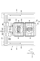
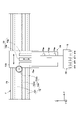
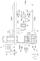
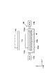
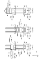
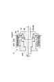
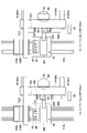
- FIG. 1 It is a figure showing typically composition of a cutting device concerning one embodiment of the present invention. It is a perspective view which shows typically the table for cutting of the same embodiment, and its peripheral structure. It is the figure (plan view) seen from the Z direction which shows typically the structure of the cutting table of the same embodiment, and its peripheral structure. It is the figure (front view) seen from the Y direction which shows typically the structure of the cutting table of the same embodiment, and its peripheral structure. It is the figure (front view) seen from the Y direction which shows typically the structure of the 1st holding mechanism of the same embodiment, and the moving mechanism for conveyance. It is the figure (side view) which showed typically the structure of the 1st holding mechanism of the same embodiment, and the moving mechanism for conveyance seen from the X direction.
- 11 is a cross-sectional view schematically showing a state before removal of the blade by the blade replacement mechanism of the modified example; It is the figure (top view) seen from the Z direction which shows the exchange state of each blade by the blade exchange mechanism of the same embodiment.
- 5 is a flow chart of a full-cut conveying operation and a half-cut conveying operation of the embodiment;
- the processing apparatus of the present invention includes a processing table on which an object to be processed is processed by a processing mechanism, a processing moving mechanism for moving the processing mechanism in first and second directions perpendicular to each other on a horizontal plane, a working tool exchange mechanism for exchanging the working tool of the working mechanism, wherein the working movement mechanism includes a pair of first guide rails provided along the first direction with the working table interposed therebetween; and a support that moves along the first guide rail of and supports the processing mechanism movably along the second direction, wherein the processing tool exchange mechanism is configured to replace the processing tool It is characterized by having a processing tool holding portion for holding and a holding portion moving mechanism for moving the processing tool holding portion in the second direction.
- the processing moving mechanism moves the processing mechanism in the first and second directions perpendicular to each other on the horizontal plane. Objects can be processed. For this reason, a moving mechanism for moving the processing table can be made unnecessary, so that the apparatus configuration can be simplified and the footprint can be reduced. Further, since the moving direction (first direction) of the support that supports the processing mechanism movably in the second direction and the moving direction (second direction) of the holding portion moving mechanism that moves the holding portion are orthogonal to each other, The support can be moved in the first direction to bring the processing mechanism closer to the processing tool exchange mechanism, and the holding portion moving mechanism can move the processing tool holding portion in the second direction to exchange the processing tool of the processing mechanism. . As described above, according to the present invention, the processing moving mechanism for moving the processing mechanism and the holding portion moving mechanism of the processing tool exchange mechanism can be optimally arranged. can be reduced.
- a processing apparatus has a first holding mechanism for holding the workpiece to be conveyed to the processing table, and a transfer shaft for moving the first holding mechanism along the first direction. It is desirable to have a movement mechanism for. With this configuration, since the transfer shaft extends in the first direction, the extending direction of the transfer shaft and the moving direction of the holding portion moving mechanism are perpendicular to each other in plan view. Further, the transfer shaft and the support are orthogonal to each other in plan view, and the extending direction of the transfer shaft and the moving direction of the support are parallel to each other in plan view. Due to this relationship, it becomes possible to optimally arrange the working moving mechanism, the working tool changing mechanism and the transfer shaft.
- the first holding mechanism When dressing the processing tool, a dressing member is used. At this time, it is preferable that the first holding mechanism has a dressing member holding portion that holds a dressing member for dressing the processing tool. With this configuration, the first holding mechanism that holds the workpiece holds the dressing member, so there is no need to provide a separate dressing member holding mechanism, and the device configuration can be simplified.
- the processing apparatus of the present invention include a plurality of processing tables along the first direction.
- a plurality of processing tables are arranged along the first direction, it is possible to move the processing mechanisms to the plurality of processing tables using a single processing moving mechanism. As a result, the device configuration can be simplified.
- the processing apparatus of the present invention further include a dressing table for dressing the processing tool using a dressing member.
- the dressing table is preferably provided between the processing tables in order to reduce the footprint of the apparatus.
- the processing apparatus of the present invention includes a processing object storage unit that stores a processing object, a receiving stage that receives the processing object from the processing object storage unit, and the receiving stage along the second direction. It is desirable to further include a stage moving mechanism that has moving rails for moving and moves the receiving stage to the transport position.
- a stage moving mechanism that has moving rails for moving and moves the receiving stage to the transport position.
- the processing apparatus of the present invention further includes a dressing member accommodating section that accommodates a dressing member for dressing the processing tool.
- the dressing member accommodating section is provided movably along the moving rail.
- the processing mechanism When the processing apparatus of the present invention is a cutting apparatus, the processing mechanism includes a blade as the processing tool, a spindle section for rotating the blade, and a flange for detachably fixing the blade to the spindle section. configuration.
- the working tool exchange mechanism is provided separately from the first suction part, which is the working tool holding part that suctions and holds the blade, and the first suction part, and suctions and holds the flange.
- a suction surface of the flange that is attracted by the second suction portion is preferably a plane perpendicular to the rotation axis of the spindle portion.
- a method for manufacturing a processed product using the processing apparatus described above is also an aspect of the present invention.
- the processing apparatus 100 of the present embodiment is a cutting apparatus that separates a sealed substrate W, which is an object to be processed, into a plurality of products P, which are processed products.
- the cutting apparatus 100 includes two cutting tables (processing tables) 2A and 2B that hold the sealed substrate W, and the sealed substrate W on the cutting tables 2A and 2B.
- a first holding mechanism 3 that holds the sealed substrate W for transportation
- a cutting mechanism (processing mechanism) 4 that cuts the sealed substrate W held on the cutting tables 2A and 2B, and a plurality of products P a transfer table 5 to which the are transferred
- a second holding mechanism 6 for holding a plurality of products P in order to transfer the plurality of products P from the cutting tables 2A and 2B to the transfer table 5
- a transfer moving mechanism 7 having a common transfer shaft 71 for moving the second holding mechanism 6, and a cutting mechanism 4 for moving the sealed substrate W held by the cutting tables 2A and 2B.
- a moving mechanism (processing moving mechanism) 8 is provided.
- the sealed substrate W is a substrate to which electronic elements such as a semiconductor chip, a resistor element, a capacitor element, etc. are connected, and at least the electronic elements are resin-molded so as to be resin-sealed.
- a lead frame and a printed wiring board can be used as the substrate constituting the sealed substrate W.
- semiconductor substrates including semiconductor wafers such as silicon wafers
- metal substrates metal substrates
- ceramic substrates can be used.
- a glass substrate, a resin substrate, or the like can be used.
- the substrates constituting the sealed substrate W may or may not be wired.
- the directions orthogonal to each other in the plane (horizontal plane) along the upper surfaces of the cutting tables 2A and 2B are the X direction and the Y direction, respectively, and the vertical direction orthogonal to the X direction and the Y direction is the Z direction.
- the horizontal direction in FIG. 1 is the X direction (first direction)
- the vertical direction is the Y direction (second direction).
- the X direction is the direction in which the support 812 moves
- the two cutting tables 2A, 2B are fixed in the X, Y and Z directions.
- the cutting table 2A can be rotated in the .theta. direction by a rotating mechanism 9A provided below the cutting table 2A.
- the cutting table 2B can be rotated in the .theta. direction by a rotating mechanism 9B provided under the cutting table 2B.
- These two cutting tables 2A and 2B are provided along the X direction on the horizontal plane. Specifically, the two cutting tables 2A and 2B are arranged such that their upper surfaces are positioned on the same horizontal plane (located at the same height in the Z direction) (see FIG. 4), and their The centers of the upper surfaces (specifically, the centers of rotation of the rotation mechanisms 9A and 9B) are arranged on the same straight line extending in the X direction (see FIGS. 2 and 3).
- the two cutting tables 2A and 2B suck and hold the sealed substrate W, and as shown in FIG.
- Two vacuum pumps 10A, 10B are arranged.
- Each vacuum pump 10A, 10B is, for example, a water ring vacuum pump.
- the pipes (not shown) connected from the vacuum pumps 10A and 10B to the cutting tables 2A and 2B can be shortened, and the pipe pressure It is possible to reduce the loss and prevent the deterioration of the adsorption force. As a result, even a very small package of, for example, 1 mm square or less can be reliably attracted to the cutting tables 2A and 2B.
- the capacities of the vacuum pumps 10A and 10B can be reduced, leading to miniaturization and cost reduction.
- the first holding mechanism 3 holds the sealed substrate W in order to transport the sealed substrate W from the substrate supply mechanism 11 to the cutting tables 2A and 2B.
- the first holding mechanism 3 includes a suction head 31 provided with a plurality of suction portions 311 for sucking and holding the sealed substrate W, and a suction portion of the suction head 31. 311 and a vacuum pump (not shown). Then, the suction head 31 is moved to a desired position by a transfer mechanism 7 or the like, which will be described later, to transfer the sealed substrate W from the substrate supply mechanism 11 to the cutting tables 2A and 2B.
- the substrate supply mechanism 11 includes a substrate accommodation portion 111 that accommodates a plurality of sealed substrates W from the outside, and a first holding portion for the sealed substrates W accommodated in the substrate accommodation portion 111 . and a substrate supply unit 112 for moving to a holding position RP where the mechanism 3 sucks and holds the substrate.
- This holding position RP is set so as to be aligned with the two cutting tables 2A and 2B in the X direction.
- the substrate supply mechanism 11 may have a substrate heating unit 113 that heats the sealed substrate W to be attracted by the first holding mechanism 3 so as to make the sealed substrate W flexible and facilitate the attraction.
- substrate accommodation part 111 is corresponded to a workpiece accommodation part.
- the substrate accommodation unit 111 may be configured to directly accommodate a plurality of sealed substrates W that are objects to be processed, or may be a container that accommodates a plurality of sealed substrates W that are objects to be processed. It may be configured to accommodate certain magazines. Other specific configurations of the substrate supply mechanism 11 will be described later.
- the cutting mechanism 4 as shown in FIGS. 1, 2 and 3, has two rotary tools 40 consisting of blades 41A and 41B corresponding to working tools and two spindles 42A and 42B.
- the two spindle parts 42A and 42B are provided so that their rotation axes are along the Y direction, and the blades 41A and 41B attached to them are arranged so as to face each other (see FIG. 3).
- the blade 41A of the spindle section 42A and the blade 41B of the spindle section 42B cut the sealed substrate W held on each cutting table 2A, 2B by rotating in a plane including the X direction and the Z direction. As shown in FIGS.
- the cutting apparatus 100 of the present embodiment has an injection nozzle 121 for injecting cutting water (working fluid) to suppress frictional heat generated by the blades 41A and 41B.
- a feed mechanism 12 is provided.
- This injection nozzle 121 is supported by, for example, a Z-direction moving unit 83, which will be described later.
- the transfer table 5 of the present embodiment is a table to which a plurality of products P inspected by an inspection unit 13, which will be described later, are transferred.
- This transfer table 5 is a so-called index table, and a plurality of products P are temporarily placed thereon before sorting the plurality of products P onto various trays 21 .
- the transfer table 5 and the two cutting tables 2A and 2B are arranged in a line along the X direction on the horizontal plane.
- the transfer table 5 is movable back and forth along the Y direction, and can move up to the sorting mechanism 20 .
- a plurality of products P placed on the transfer table 5 are sorted into various trays 21 by the sorting mechanism 20 according to the inspection results (good products, defective products, etc.) by the inspection unit 13 .
- the tray housing unit 23 includes, for example, a tray 21 before housing the product P, a tray 21 housing a non-defective product P, and a tray 21 housing a defective product P that requires rework (reinspection). It is configured to accommodate three types of trays 21 such as.
- the inspection unit 13 is provided between the cutting tables 2A and 2B and the transfer table 5, and inspects the plurality of products P held by the second holding mechanism 6.
- the inspection unit 13 of this embodiment has a first inspection unit 131 that inspects the sealing surface (package surface) of the product P and a second inspection unit 132 that inspects the lead surface of the product P.
- the first inspection unit 131 is an imaging camera having an optical system for inspecting the package surface
- the second inspection unit 132 is an imaging camera having an optical system for inspecting the lead surface. Note that the first inspection unit 131 and the second inspection unit 132 may be shared.
- the sealed substrate W and the product P of this embodiment are configured such that one surface of the substrate is molded with resin.
- the resin-molded surface is the surface on which the electronic element connected to the substrate is resin-sealed, and is called a “sealing surface” or a “package surface”.
- the non-resin-molded surface opposite to the resin-molded surface is called the lead surface because the leads functioning as external connection electrodes of the product are usually exposed.
- this lead is a protruding electrode used in an electronic component such as a BGA (Ball Grid Array), it is sometimes called a "ball surface".
- the non-resin-molded surface opposite to the resin-molded surface may be called a "substrate surface" because there are some forms in which leads are not formed.
- the resin-molded surface is referred to as the “sealing surface” or "package surface”
- the resin-molded surface opposite to the resin-molded surface is referred to as the "lead surface”.
- a reversing mechanism 14 for reversing the plurality of products P is provided so that both sides of the plurality of products P can be inspected by the inspection unit 13 (see FIG. 1).
- the reversing mechanism 14 has a holding table 141 that holds a plurality of products P, and a reversing unit 142 such as a motor that turns the holding table 141 upside down.
- the package surface of the products P faces downward.
- the first inspection unit 131 inspects the package surfaces of the products P.
- the multiple products P held by the second holding mechanism 6 are reversed by the reversing mechanism 14 .
- the lead surface of the product P faces downward, and the lead surface of the product P is inspected by moving the reversing mechanism 14 to the second inspection unit 132 .
- the second holding mechanism 6 holds a plurality of products P in order to convey the plurality of products P from the cutting tables 2A and 2B to the transfer table 5, as shown in FIG.
- the second holding mechanism 6 is connected to a suction head 61 provided with a plurality of suction portions 611 for sucking and holding a plurality of products P, and the suction portions 611 of the suction head 61 . and a vacuum pump (not shown). Then, the suction head 61 is moved to a desired position by a transfer mechanism 7 or the like, which will be described later, to transfer the plurality of products P from the cutting tables 2A and 2B to the holding table 141 or the transfer table 5 .
- the transportation moving mechanism 7 moves the first holding mechanism 3 between at least the substrate supply mechanism 11 and the cutting tables 2A and 2B, and moves the second holding mechanism 6 between at least the cutting tables. It is moved between 2A, 2B and the holding table 141 .
- the transportation moving mechanism 7 extends in a straight line along the arrangement direction (X direction) of the two cutting tables 2A and 2B and the transfer table 5, and the first holding mechanism 3 and the second 2 has a common transfer shaft 71 for moving the holding mechanism 6 .
- the transfer shaft 71 is provided within a range in which the first holding mechanism 3 can move above the substrate supply section 112 of the substrate supply mechanism 11 and the second holding mechanism 6 can move above the transfer table 5 ( See Figure 1).
- the first holding mechanism 3, the second holding mechanism 6, the cutting tables 2A and 2B, and the transfer table 5 are provided on the same side (front side) of the transfer shaft 71 in plan view.
- the inspection section 13, the reversing mechanism 14, various trays 21, the tray conveying mechanism 22, the tray accommodating section 23, the first cleaning mechanism 18 and the second cleaning mechanism 19 described later, and the collection container 172 are the same with respect to the transfer shaft 71. provided on the side (front side).
- the transporting moving mechanism 7 includes a main moving mechanism 72 that moves the first holding mechanism 3 and the second holding mechanism 6 in the X direction along the transfer shaft 71; A vertical movement mechanism 73 for vertically moving the first holding mechanism 3 and the second holding mechanism 6 with respect to the transfer shaft 71 in the Z direction, and a vertical movement mechanism 73 for vertically moving the first holding mechanism 3 and the second holding mechanism 6 with respect to the transfer shaft 71 in the Y direction. and a horizontal movement mechanism 74 for horizontal movement.
- the main moving mechanism 72 is provided on the transfer shaft 71 and has a common guide rail 721 for guiding the first holding mechanism 3 and the second holding mechanism 6. and a rack-and-pinion mechanism 722 for moving the first holding mechanism 3 and the second holding mechanism 6 .
- the guide rail 721 extends straight in the X direction along the transfer shaft 71, and, like the transfer shaft 71, allows the first holding mechanism 3 to move above the substrate supply portion 112 of the substrate supply mechanism 11, 2 A holding mechanism 6 is provided within a range in which it can move above the transfer table 5 .
- the guide rail 721 is slidably provided with a slide member 723 on which the first holding mechanism 3 and the second holding mechanism 6 are provided via a vertical movement mechanism 73 and a horizontal movement mechanism 74 .
- the guide rail 721 is common to the first holding mechanism 3 and the second holding mechanism 6, but the vertical movement mechanism 73, the horizontal movement mechanism 74 and the slide member 723 are common to the first holding mechanism 3 and the second holding mechanism 6. provided separately for each.
- the rack and pinion mechanism 722 includes a cam rack 722a common to the first holding mechanism 3 and the second holding mechanism 6, and a pinion provided in each of the first holding mechanism 3 and the second holding mechanism 6 and rotated by an actuator (not shown). and a gear 722b.
- the cam rack 722a is provided on the common transfer shaft 71 and can be varied in length by connecting a plurality of cam rack elements.
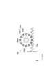
- the pinion gear 722b is provided on the slide member 723 and is called a so-called roller pinion. As shown in FIG. It has a plurality of roller pins 722b2 which are provided at equal intervals in the circumferential direction between the roller bodies 722b1 and are provided so as to be able to roll with respect to the roller body 722b1.
- the rack-and-pinion mechanism 722 of this embodiment uses the roller pinions described above, two or more roller pins 722b2 come into contact with the cam rack 722a. Positioning accuracy is improved when moving the first holding mechanism 3 and the second holding mechanism 6 in the X direction.
- the lifting mechanism 73 is provided corresponding to each of the first holding mechanism 3 and the second holding mechanism 6.
- the lifting mechanism 73 of the first holding mechanism 3 is interposed between the transfer shaft 71 (specifically, the main moving mechanism 72) and the first holding mechanism 3, as shown in FIGS. It has a Z-direction guide rail 73a provided along the Z-direction, and an actuator portion 73b for moving the first holding mechanism 3 along the Z-direction guide rail 73a.
- the actuator section 73b may use, for example, a ball screw mechanism, an air cylinder, or a linear motor.
- the configuration of the up-and-down movement mechanism 73 of the second holding mechanism 6 is the same as that of the up-and-down movement mechanism 73 of the first holding mechanism 3, as shown in FIG.
- the horizontal movement mechanism 74 is provided corresponding to each of the first holding mechanism 3 and the second holding mechanism 6, as shown in FIGS.
- the horizontal movement mechanism 74 of the first holding mechanism 3 is interposed between the transfer shaft 71 (specifically, the vertical movement mechanism 73) and the first holding mechanism 3, as shown in FIGS. Y-direction guide rails 74a provided along the Y-direction, elastic bodies 74b for applying force to the first holding mechanism 3 on one side of the Y-direction guide rails 74a, and the first holding mechanism 3. and a cam mechanism 74c for moving to the other side of the Y-direction guide rail 74a.
- the cam mechanism 74c uses an eccentric cam, and the amount of movement of the first holding mechanism 3 in the Y direction can be adjusted by rotating the eccentric cam with an actuator such as a motor.
- the configuration of the horizontal movement mechanism 74 of the second holding mechanism 6 is the same as that of the vertical movement mechanism 73 of the first holding mechanism 3, as shown in FIG. Further, the second holding mechanism 6 may be configured without the horizontal movement mechanism 74 , or both the first holding mechanism 3 and the second holding mechanism 6 may be configured without the horizontal movement mechanism 74 . Further, the horizontal movement mechanism 74 may use, for example, a ball screw mechanism or an air cylinder without using the cam mechanism 74c, like the elevation movement mechanism 73. Alternatively, a linear motor may be used.
- the cutting movement mechanism 8 linearly moves the two spindles 42A and 42B independently in the X, Y and Z directions.
- the cutting movement mechanism 8 includes an X-direction movement section 81 that linearly moves the spindle sections 42A and 42B in the X direction, and the spindle sections 42A and 42B. and a Z-direction moving portion 83 for linearly moving the spindle portions 42A and 42B in the Z-direction.
- the X-direction moving part 81 is common to the two cutting tables 2A and 2B, and is provided along the X direction with the two cutting tables 2A and 2B interposed therebetween, as particularly shown in FIGS. and a pair of X-direction guide rails (first guide rails) 811, and along the pair of X-direction guide rails 811, the spindle portion 42A, and a support 812 that supports 42B.
- a pair of X-direction guide rails 811 are provided on the sides of the two cutting tables 2A and 2B provided along the X-direction.
- the support 812 is, for example, a portal type and has a shape extending in the Y direction. Specifically, the support 812 has a pair of legs extending upward from the pair of X-direction guide rails 811 and beams (beams) bridging the pair of legs. extending in the direction
- the support 812 is linearly reciprocated along the X direction on a pair of X direction guide rails 811 by, for example, a ball screw mechanism 813 extending in the X direction.
- the ball screw mechanism 813 is driven by a drive source (not shown) such as a servomotor.
- the support 812 may be configured to reciprocate by another linear motion mechanism such as a linear motor.
- the Y-direction moving part 82 includes a Y-direction guide rail 821 provided along the Y direction on the support 812, and a Y-direction slider 822 that moves along the Y-direction guide rail 821. have.
- the Y-direction slider 822 is driven by, for example, a linear motor 823 and linearly reciprocates on the Y-direction guide rail 821 .
- two Y-direction sliders 822 are provided corresponding to the two spindle portions 42A and 42B. Thereby, the two spindle parts 42A and 42B are movable in the Y direction independently of each other.
- the Y-direction slider 822 may be configured to reciprocate by another direct acting mechanism using a ball screw mechanism.
- the Z-direction moving part 83 moves along a Z-direction guide rail 831 provided along the Z-direction on each Y-direction slider 822 and moves along the Z-direction guide rail 831. and a Z-direction slider 832 that supports the spindle portions 42A and 42B. That is, the Z-direction moving portion 83 is provided corresponding to each spindle portion 42A, 42B.
- the Z-direction slider 832 is driven by, for example, an eccentric cam mechanism (not shown), and linearly reciprocates on the Z-direction guide rail 831 .
- the Z-direction slider 832 may be configured to reciprocate by another direct acting mechanism such as a ball screw mechanism.
- the positional relationship between the moving mechanism 8 for cutting and the transfer shaft 71 is such that the transfer shaft 71 is arranged above the moving mechanism 8 for cutting so as to cross the moving mechanism 8 for cutting. ing.
- the transfer shaft 71 is arranged above the support 812 so as to traverse the support 812, and the transfer shaft 71 and the support 812 are in a positional relationship orthogonal to each other in plan view.
- the cutting apparatus 100 of the present embodiment further includes a processing waste storage section 17 that stores processing waste S such as offcuts generated by cutting the sealed substrate W, as shown in FIG.
- the processing waste container 17 is provided below the cutting tables 2A and 2B, and is a guide chute having an upper opening 171X surrounding the cutting tables 2A and 2B in plan view. 171 and a collection container 172 for collecting the processing waste S guided by the guide shooter 171 .
- the recovery rate of the processing waste S can be improved.
- the guide shooter 171 guides the processing waste S scattered or dropped from the cutting tables 2A, 2B to the collection container 172.
- the upper opening 171X of the guide shooter 171 surrounds the cutting tables 2A and 2B (see FIG. 3)
- it is difficult to remove the processing waste S, and the collection rate of the processing waste S is further improved. can be improved.
- the guide shooter 171 is provided so as to surround the rotating mechanisms 9A and 9B provided under the cutting tables 2A and 2B (see FIG. 4). is configured to protect
- the processing waste container 17 is shared by the two cutting tables 2A and 2B, but may be provided for each of the cutting tables 2A and 2B.
- the collection container 172 is for collecting the processing waste S that has passed through the guide shooter 171 by its own weight.
- the two collection containers 172 are arranged on the front side of the transfer shaft 71 and configured to be independently removable from the front side of the cutting device 100 . With this configuration, it is possible to improve maintainability such as disposal of the processing waste S. Considering the size of the sealed substrate W, the size and amount of the processing waste S, the workability, etc., one collection container 172 may be provided under the entire cutting table, or three collection containers may be provided. The above may be set.
- the processing waste storage section 17 has a separating section 173 for separating cutting water and processing waste.
- a filter such as a perforated plate that allows cutting water to pass through the bottom surface of the collection container 172 may be provided.
- the separation unit 173 allows the processing waste S to be collected without accumulating cutting water in the collection container 172 .
- the cutting apparatus 100 of the present invention includes a first cleaning mechanism 18 that cleans the upper surfaces (lead surfaces) of the plurality of products P held on the cutting tables 2A and 2B. I have more.
- the first cleaning mechanism 18 cleans the upper surfaces of the products P by means of injection nozzles 18a (see FIG. 5) that inject cleaning liquid and/or compressed air onto the upper surfaces of the plurality of products P held on the cutting tables 2A and 2B. It is for cleaning.
- the first cleaning mechanism 18 is configured to be movable along the transfer shaft 71 together with the first holding mechanism 3, as shown in FIG.
- the first cleaning mechanism 18 is provided on a slide member 723 that slides on a guide rail 721 provided on the transfer shaft 71 .
- an elevation movement mechanism 181 for vertically moving the first cleaning mechanism 18 in the Z direction.
- the lifting mechanism 181 may be, for example, one using a rack and pinion mechanism, one using a ball screw mechanism, or one using an air cylinder.
- the cutting device 100 of the present invention further includes a second cleaning mechanism 19 that cleans the lower surface side (package surface) of the plurality of products P held by the second holding mechanism 6, as shown in FIG. .
- the second cleaning mechanism 19 is provided between the cutting table 2B and the inspection section 13, and sprays cleaning liquid and/or compressed air onto the lower surfaces of the plurality of products P held by the second holding mechanism 6. By doing so, the lower surface side of the product P is cleaned. That is, the second cleaning mechanism 19 cleans the lower surface side of the product P while the second holding mechanism 6 is being moved along the transfer shaft 71 .
- FIG. 9 shows the moving path of the first holding mechanism 3 and the moving path of the second holding mechanism 6 in the operation of the cutting device 10.
- all operations and controls of the cutting apparatus 100 such as transportation of the sealed substrate W, cutting of the sealed substrate W, inspection of the product P, replacement of the blade described later, dressing, etc. is performed by the control unit CTL (see FIG. 1).
- the substrate supply unit 112 of the substrate supply mechanism 11 moves the sealed substrate W accommodated in the substrate accommodation unit 111 toward the holding position RP held by the first holding mechanism 3 .
- the transport moving mechanism 7 moves the first holding mechanism 3 to the holding position RP, and the first holding mechanism 3 holds the sealed substrate W by suction.
- the transfer moving mechanism 7 moves the first holding mechanism 3 holding the sealed substrate W to the cutting tables 2A and 2B, and the first holding mechanism 3 releases the suction holding, and the sealed substrate W is released.
- a substrate W is placed on the cutting tables 2A and 2B.
- the main moving mechanism 72 adjusts the position of the sealed substrate W in the X direction
- the horizontal moving mechanism 74 adjusts the position of the sealed substrate W in the Y direction.
- the cutting tables 2A and 2B hold the sealed substrate W by suction.
- the elevation movement mechanism 73 moves the first holding mechanism 3 to the cutting movement mechanism 8 (support body 812). Raise to a position where there is no physical interference.
- the support body 812 is retracted from the cutting table 2B to the transfer table 5 side. It is not necessary to raise and lower the first holding mechanism 3 at this time.
- the cutting movement mechanism 8 sequentially moves the two spindles 42A and 42B in the X direction and the Y direction, and the cutting tables 2A and 2B rotate to form the sealed substrate W in a grid pattern. Cut and individualize.
- the transfer mechanism 7 moves the first cleaning mechanism 18 to clean the upper surface side (lead surface) of the multiple products P held on the cutting tables 2A and 2B. After this cleaning, the transfer mechanism 7 retracts the first holding mechanism 3 and the first cleaning mechanism 18 to predetermined positions.
- the transfer movement mechanism 7 moves the second holding mechanism 6 to the cutting tables 2A and 2B after cutting, and the second holding mechanism 6 holds the plurality of products P by suction.
- the transport moving mechanism 7 moves the second holding mechanism 6 holding the plurality of products P to the second cleaning mechanism 19 .
- the second cleaning mechanism 19 cleans the lower surface side (package surface) of the plurality of products P held by the second holding mechanism 6 .
- the multiple products P held by the second holding mechanism 6 are double-sided inspected by the inspection unit 13 and the reversing mechanism 14 .
- the transfer movement mechanism 7 moves the second holding mechanism 6 to the transfer table 5
- the second holding mechanism 6 releases the suction holding, and places the plurality of products P on the transfer table 5 .
- a plurality of products P placed on the transfer table 5 are sorted into various trays 21 by the sorting mechanism 20 according to the inspection results (good products, defective products, etc.) by the inspection unit 13 .
- the double-sided inspection for example, first, one side of the product P is inspected while being sucked and held by the second holding mechanism 6 . Next, the product P is transferred from the second holding mechanism 6 to the holding table 141 of the reversing mechanism 14, and the other side of the product P is inspected while being sucked and held by the holding table 141 after reversing. inspection can be performed. Subsequently, the product P can be transferred from the reversing mechanism 14 to the transfer table 5 by transferring it from the holding table 141 to the second holding mechanism 6 .
- the holding table 141 is configured to be movable in the X direction, and at least one of the holding table 141 and the transfer table 5 is configured to be movable in the Z direction, and the holding table 141 is moved above the transfer table 5.
- the product P can also be transported to the transfer table 5 and transferred.
- the substrate supply mechanism 11 supplies the sealed substrate W to the first holding mechanism 3 as described above.
- the substrate supply mechanism 11 includes a substrate accommodation portion 111 in which a plurality of sealed substrates W are accommodated from the outside, and a substrate accommodation portion 111 in which a plurality of sealed substrates W are accommodated. and a substrate supply unit 112 for moving the sealed substrate W to a holding position RP where the first holding mechanism 3 sucks and holds the substrate W.
- a substrate accommodation portion 111 in which a plurality of sealed substrates W are accommodated from the outside
- a substrate accommodation portion 111 in which a plurality of sealed substrates W are accommodated.
- a substrate supply unit 112 for moving the sealed substrate W to a holding position RP where the first holding mechanism 3 sucks and holds the substrate W.
- the substrate housing portion 111 is provided with an extrusion mechanism 114 that pushes out part of the sealed substrate W contained therein to the outside of the substrate housing portion 111 .
- the push-out mechanism 114 has a movable push member 114a that pushes one end of the sealed substrate W, and an actuator section 114b that moves the push member 114a.
- the actuator section 114b one using a motor, one using an air cylinder, one using a solenoid, or the like can be used.
- the substrate supply unit 112 moves the sealed substrate W from the substrate storage unit 111 to the reception stage 115 that receives the sealed substrate W from the substrate storage unit 111 and to the reception stage 115.
- a substrate moving unit 116 and a stage moving mechanism 117 for moving the receiving stage 115 to a predetermined transport position X2 are provided.
- the receiving stage 115 of the present embodiment is configured not only to receive the sealed substrate W from the substrate housing portion 111 but also to transfer the sealed substrate W to the substrate housing portion 111. ing. Specifically, the receiving stage 115 has a loading stage 115A for receiving the sealed substrate W from the substrate housing portion 111 and an unloading stage 115B for delivering the sealed substrate W to the substrate housing portion 111.
- the loading stage 115A is a suction stage, and can hold the mounted sealed substrate W by suction.
- the unloading stage 115B of the present embodiment delivers the sealed substrate W that has been half-cut. Half-cutting is a process of forming a groove by cutting a part of the upper surface (lead surface) of the sealed substrate W. As shown in FIG.
- the sealed substrate W placed on the loading stage 115A is heated while being pressed against the upper surface of the loading stage 115A by the substrate heating unit 113 from above.
- the loading stage 115A is provided with a sheet-like cushion material 115x that absorbs the impact when heated by the substrate heating section 113. As shown in FIG.
- the loading stage 115A is provided with a positioning mechanism 118 for positioning the sealed substrate W, as shown in FIG.
- this positioning mechanism 118 one side wall 115m of a pair of side walls 115m and 115n of the carrying-in stage 115A is movable with respect to the other side wall 115n.
- the finished substrate W hits the other side wall 115n and is positioned with reference to the inner surface of the other side wall 115n.
- one side wall 115m is movable by an actuator 115j
- the other side wall 115n is movable by an actuator 115k.
- the substrate moving part 116 includes a clip part 116a that clamps the edge of the sealed substrate W, an X-direction moving part 116b that moves the clip part 116a in the X direction, and a Z-direction moving part 116b that moves the clip part 116a. and a Z-direction moving part 116c for moving in the direction.
- the transfer procedure of the sealed substrate W from the substrate storage section 111 to the receiving stage 115 (the loading stage 115A and the unloading stage 115B) using the pushing mechanism 114 and the substrate moving section 116 is as follows.
- the sealed substrate W accommodated in the substrate accommodation portion 111 is pushed by the push member 114a of the pushing mechanism 114, and part of the sealed substrate W is ejected from the substrate accommodation portion 111 to the carry-in stage 115A side.
- the portion of the sealed substrate W protruding from the substrate accommodating portion 111 is clamped by the clip portion 116a of the substrate moving portion 116, and the clip portion 116a is moved in the X direction by the X direction moving portion 116b to move the sealed substrate W. is pulled out from the substrate accommodating portion 111 and placed on the loading stage 115A.
- the stage moving mechanism 117 includes a pair of moving rails 117a for moving the receiving stage 115 (the loading stage 115A and the unloading stage 115B), and the moving rails 117a. and a slide member 117b on which the receiving stage 115 is provided.
- the slide member 117b is linearly reciprocated along the Y direction on the pair of moving rails 117a by, for example, a ball screw mechanism 117c extending in the Y direction.
- the ball screw mechanism 117c is driven by a drive source (not shown) such as a servomotor.
- the slide member 117b may be configured to reciprocate by another linear motion mechanism such as a linear motor.
- the moving rail 117a is positioned below the transfer shaft 71, and the moving rail 117a and the transfer shaft 71 of the transfer moving mechanism 7 are orthogonal to each other in plan view.
- the transfer shaft 71 extends in the X direction and the moving rail 117a extends in the Y direction.
- perpendicular to each other in plan view includes not only the fact that the transfer shaft 71 and the moving rail 117a intersect perpendicularly (at 90 degrees), but also the fact that they are substantially perpendicular to each other.
- “Substantially orthogonal” means a state in which they intersect perpendicularly with a slight error, for example, a state in which they intersect at 85° or more and 95° or less.
- the moving rail 117a is perpendicular to the transfer shaft 71, the moving rail 117a is perpendicular to the X-direction guide rail 811 for moving the support 812 of the moving mechanism 8 for cutting. In other words, the moving rail 117a is parallel to the support 812 of the cutting moving mechanism 8 in plan view.
- the peripheral structures of the transfer shaft 71 and the moving rail 117a are mentioned.
- the substrate accommodating portion 111 is provided on the back side of the transfer shaft 71 in the Y direction
- the first holding mechanism 3 is provided on the front side of the transfer shaft 71 in the Y direction.
- the stage moving mechanism 117 moves the loading stage 115A to the receiving position X1 where the sealed substrate W is received from the substrate accommodation section 111 and the sealed substrate W by the first holding mechanism 3. It is linearly moved between the held transport position X2.
- the receiving position X1 is located on the back side of the transfer shaft 71 in the Y-axis direction
- the transporting position X2 is located on the front side of the transfer shaft 71 in the Y-axis direction.
- the sealed substrate W on the receiving stage 115 (loading stage 115A) at the transport position X2 is positioned at the holding position RP.
- the stage moving mechanism 117 moves the loading stage 115A to the heating position X3 for heating the mounted sealed substrate W by the substrate heating unit 113 (see FIG. 13).
- the heating position X3 in this embodiment is set on the back side in the Y direction from the receiving position X1.
- the substrate heating unit 113 contacts the upper surface of the sealed substrate W placed on the loading stage 115A and heats the sealed substrate W. As shown in FIG.
- the stage moving mechanism 117 moves the unloading stage 115B to the transport position X2.
- the first holding mechanism 3 transports the half-cut sealed substrate W to the unloading stage 115B.
- the stage moving mechanism 117 moves the unloading stage 115B to the receiving position X1.
- the sealed substrate W is accommodated in the substrate accommodation portion 111 from the unloading stage 115B by the substrate moving portion 116 .
- an accommodation position for accommodating the sealed substrate W is separately set, and the sealed substrate W is received at the accommodation position. It may be housed in the housing portion 111 .
- the cutting device 100 of this embodiment has a blade replacement mechanism 24 that automatically replaces the blades 41A and 41B.
- the blade exchange mechanism 24 in this embodiment can exchange the blades 41A and 41B from the two spindle portions 42A and 42B, respectively.
- the blade exchange mechanism 24 stores the blades 41A and 41B in the blade storage section 25 while holding the removed blades 41A and 41B, holds the new blades 41A and 41B, and conveys them to the spindle sections 42A and 42B. to be installed.
- the blade exchange mechanism 24 corresponds to a working tool exchange mechanism.
- FIG. It has a pair of flanges 43, 44 which are detachably secured to 42A, 42B.
- the pair of flanges 43 and 44 are fixed to the spindle portions 42A and 42B and are detachable from the inner flange 43 closer to the spindle portions 42A and 42B and the spindle portions 42A and 42B. and an outer flange 44 remote from the .
- the outer flange 44 is attached to the central shaft portion of the inner flange 43 and fixed by a detachable member 45 such as a nut.
- the attachment/detachment member 45 allows the blades 41A and 41B to be attached to and detached from the spindle portions 42A and 42B.
- the blade replacement mechanism 24 includes an attraction arm 241 that attracts and holds the blades 41A and 41B and the outer flange 44, and the attraction arm 241 that is positioned relative to the cutting mechanism 4. and an arm moving mechanism 242 for moving.
- the arm moving mechanism corresponds to the holding portion moving mechanism.
- the suction arm 241 includes a first suction portion (processing tool holding portion) 241a that suctions and holds one surface (the surface on the side of the outer flange 44) of the blades 41A and 41B, and a first suction portion.
- a second suction portion 241b is provided inside the portion 241a and holds the outer surface of the outer flange 44 (the surface opposite to the inner flange 43) by suction.
- the adsorption arm 241 is positioned inside the second adsorption portion 241b, and is a detachable member rotating portion 241 that engages with the detachable members 45 (nuts in this case) of the spindle portions 42A and 42B to detach the detachable members 45.
- the first adsorption portion 241 a and the second adsorption portion 241 b are connected to a suction pump (not shown) provided outside the adsorption arm 241 .
- the detachable member rotating portion 241c is configured using a rotating mechanism (not shown) such as a motor for rotating the detachable member 45 .
- the outer attracting surface 44a of the outer flange 44 which is attracted by the second attracting portion 241b, has a tapered shape, but the configuration shown in FIG. 18 may be adopted.
- the outer attracting surface 44a to be attracted by the second attracting portion 241b is a flat plane orthogonal to the rotation axes of the spindle portions 42A and 42B.
- the configuration of the second adsorption portion 241b differs from that shown in FIG. 17 in that the flat has a shape corresponding to a flat surface.
- the outer flange 44 can be stably sucked and held by the second sucking portion 241b of the sucking arm 241, and the risk of the outer flange 44 falling when the sucking arm 241 is moved by the arm moving mechanism 242 is reduced. can.
- the arm moving mechanism 242 includes a Y-direction moving mechanism 242a that moves the suction arm 241 in the Y direction and an X-direction moving mechanism 242b that moves the suction arm 241 in the X direction.
- the arm moving mechanism 242 may have a mechanism for moving the adsorption arm 241 in the Z direction.
- the Y-direction movement mechanism 242a is configured using the movement rail 117a of the stage movement mechanism 117 described above, and has a Y-direction slider 242a1 that slides along the movement rail 117a.
- the Y-direction slider 242a1 is driven by, for example, a linear motor, and linearly reciprocates on the movement rail 117a.
- the Y-direction slider 242a1 may be configured to reciprocate by another direct acting mechanism using a ball screw mechanism.
- the X-direction moving mechanism 242b has an X-direction guide rail 242b2 provided along the X-direction on the Y-direction slider 242a1, and an X-direction slider 242b1 that moves along the X-direction guide rail 242b2.
- the X-direction slider 242b1 is driven by, for example, a linear motor, and linearly reciprocates on the X-direction guide rail 242b2.
- the X-direction slider 242b1 may be configured to reciprocate by another direct acting mechanism using a ball screw mechanism.
- the movement direction of the blade replacement mechanism 24 (the direction along the movement rail 117a) and the movement direction of the support body 812 in the processing movement mechanism 83 (the direction along the X-direction guide rail 811). ) are perpendicular to each other in plan view. That is, the suction arm 241 of the blade replacement mechanism 24 moves along the longitudinal direction of the support 812 .
- “perpendicular to each other in plan view” includes not only the fact that the movement rail 117a and the X-direction guide rail 811 intersect perpendicularly (90°), but also the fact that they are substantially perpendicular to each other.
- “Substantially orthogonal” means a state in which they intersect perpendicularly with a slight error, for example, a state in which they intersect at 85° or more and 95° or less.
- the processing movement mechanism 83 moves the cutting mechanism 4 to a predetermined replacement position.
- the X-direction moving unit 81 moves the support 812 toward the moving rail 117a (the blade exchange mechanism 24 side), and the Y-direction moving unit 82 (see FIG. 2) moves the cutting mechanism 4 to the support 812. By moving along, the cutting mechanism 4 is moved to the predetermined exchange position.
- the blade replacement mechanism 24 replaces the blades 41A and 41B of the cutting mechanism 4 at the predetermined replacement position.
- the arm moving mechanism 242 moves the suction arm 241 along the moving rail 117a to remove the blades 41A and 41B of the cutting mechanism 4 at the replacement position.
- the arm moving mechanism 242 moves the suction arm 241 along the moving rail 117a, and the blade replacement mechanism 24 stores the removed blades 41A and 41B in the blade storage section 25, and replaces the new blades 41A and 41B in the blade storage section. 25 and attached to the cutting mechanism 4 in the exchange position.
- the attraction arm 241 is rotated 180 degrees by a rotation mechanism (not shown) to perform the same operation.
- the cutting device 100 of the present embodiment includes a dressing member housing portion 26 housing a dressing member DP for dressing the blades 41A and 41B, and a blade 41A and 41B on which the dressing member DP is mounted. has a dressing table 27 on which is dressed.
- the dressing member storage section 26 stores a new dressing member DP and an old dressing member DP.
- the dressing member housing portion 26 of this embodiment is provided on the moving rail 117a, and more specifically, is provided on the Y-direction slider 242a1 that moves on the moving rail 117a.
- the dressing table 27 of this embodiment is provided between the two cutting tables 2A and 2B in the X direction.
- the dressing member DP is conveyed to the dressing table 27 by the first holding mechanism 3 and the conveying movement mechanism 7 .
- the dressing table 27 sucks and holds the transported dressing member DP.
- the first holding mechanism 3 is provided with a dressing member suction portion (dressing member holding portion) 32 (see FIGS. 6 and 10) for sucking and holding the dressing member DP.
- the cutting movement mechanism 8 moves the cutting mechanism 4 to the dressing table 27, and the blades 41A and 41B of the cutting mechanism 4 are dressed.
- the dressing member DP is transported from the dressing table 27 to the dressing member accommodating section 26 by the first holding mechanism 3 and the transport moving mechanism 7 .
- the full cut is a process of cutting the sealed substrate W into individual pieces.
- the loading stage 115A is moved to the transport position by the stage moving mechanism 117, the sealed substrate W is held by the first holding mechanism 3, and transported to the cutting tables 2A and 2B (loading step).
- the sealed substrate W is fully cut (cut) by the cutting tables 2A and 2B into individual pieces (full cut process).
- the product P is held by the second transport mechanism 6 and transported to the holding stage 141 of the inspection unit 14 or the transfer stage 5 (unloading process).
- the operation after that is as described in ⁇ Example of Operation of Cutting Device>.
- the loading stage 115A is moved to the transport position X2, the sealed substrate W is held by the first holding mechanism 3, and transported to the cutting tables 2A and 2B (loading step).
- the sealed substrate W is half-cut (grooved) by the cutting tables 2A and 2B (half-cutting process).
- the half-cut sealed substrate W is held by the first holding mechanism 3 and transported to the unloading stage 115B at the transport position X2 (unloading step).
- the unloading stage 115B to which the half-cut sealed substrate W has been transferred is moved to the accommodation position (receiving position X1) by the stage moving mechanism 117.
- the substrate moving unit 116 accommodates the half-cut sealed substrate W in the substrate accommodation unit 111 (accommodation step).
- the cutting mechanism 4 is moved by the cutting moving mechanism 8 in the first direction (X direction) and the second direction (Y direction) perpendicular to each other in the horizontal plane.
- the sealed substrate W can be processed without moving 2A and 2B in the X and Y directions. Therefore, a moving mechanism for moving the cutting tables 2A and 2B can be dispensed with, thereby simplifying the apparatus configuration and reducing the footprint.
- the moving direction (X direction) of the support body 812 that supports the cutting mechanism 4 so as to be movable in the Y direction and the moving direction (Y direction) of the arm moving mechanism 242 that moves the adsorption arm 241 (first adsorption portion 241a) are perpendicular to each other, the support 812 is moved in the X direction to bring the cutting mechanism 4 closer to the blade replacement mechanism 24, and the arm moving mechanism 242 moves the adsorption arm 241 (first adsorption portion 241a) in the Y direction.
- the blades 41A and 41B of the cutting mechanism 4 can be replaced.
- the cutting movement mechanism 8 for moving the cutting mechanism 4 and the arm movement mechanism 242 of the blade replacement mechanism 24 can be optimally arranged, and the footprint of the cutting device 100 can be reduced. can be done.
- the extending direction (X direction) of the transfer shaft 71 and the moving direction (Y direction) of the arm moving mechanism 242 are orthogonal to each other in plan view, and the extending direction of the transfer shaft and the moving direction of the support body are mutually perpendicular in plan view. Since they are parallel, the cutting movement mechanism 8, the blade exchange mechanism 24 and the transfer shaft 71 can be arranged optimally, thereby simplifying the apparatus configuration and reducing the footprint.
- the first holding mechanism 3 holds the dressing member DP, there is no need to provide a separate dressing member holding mechanism, and the device configuration can be simplified. Moreover, since the dressing table 27 is provided between the cutting tables 2A and 2B in the X direction, the footprint of the cutting device 100 can be reduced.
- the footprint of the cutting device 100 can be reduced by moving the receiving stage 115 in the Y direction by the moving rails 117a to the predetermined transport position X2. Specifically, since the receiving stage 115 is moved in the Y direction by the moving rails 117a, the transfer shafts 71 for moving the first holding mechanism 3 are orthogonal to each other in plan view, thereby reducing the footprint of the cutting device 100. can do.
- the arm moving mechanism 242 is configured using the moving rail 117a, the footprint of the cutting device 100 can be reduced while simplifying the device configuration.
- the dressing member housing section 26 is configured to be movable along the moving rail 117a, the configuration of the device can be simplified and the footprint of the cutting device 100 can be reduced.
- the blade exchange mechanism 24 is movable by the movement rail 117a of the stage movement mechanism 117, but it may be configured to be movable along another rail.
- the cutting apparatus 100 of the above embodiment performs both full-cutting and half-cutting operations, it may perform only full-cutting operations.
- the receiving stage 115 may be only the loading stage 115A.
- only the half-cut operation may be performed.
- a configuration for carrying out the product P such as the second holding mechanism 6 is unnecessary.
- twin-cut table system and a twin-spindle configuration cutting device have been described. It may also be a cutting device with a twin spindle configuration.
- the transfer table 5 of the above embodiment is an index table that is temporarily placed before sorting into the various trays 21 , but the transfer table 5 may be used as the holding table 141 of the reversing mechanism 14 .
- the transfer table 5 is sorted into the tray 21, but the product P may be conveyed and attached to the adhesive tape arranged inside the frame-shaped member.
- the cutting device (processing device) 100 can be separated and connected between the second cleaning mechanism 19 and the inspection unit 13. It can be configured as a removable (detachable) module. In this case, for example, between the module on the second cleaning mechanism 19 side and the module on the inspection section 13 side, a module that performs an inspection different from the inspection performed by the inspection section 13 can be added.
- the cutting device (processing device) 100 may have a module configuration that can be separated and connected (detachable) at any point, and the modules to be added may be modules with various functions other than inspection. .
- processing apparatus of the present invention may perform processing other than cutting, and may perform other mechanical processing such as cutting and grinding.
- Processing device Sealed substrate (object to be processed) P ⁇ Product (processed product) 2A, 2B... Cutting table (processing table) 3 First holding mechanism 4 Cutting mechanism (processing mechanism) 6 Second holding mechanism 7 Transportation movement mechanism 71 Transfer shaft 8 Cutting movement mechanism (processing movement mechanism) 811 ... X-direction guide rail (first guide rail) 812... Support body 115... Receiving stage 117a... Moving rail 117... Stage moving mechanism 24... Blade changing mechanism (processing tool changing mechanism) 241a... First adsorption part (processing tool holding part) 242... Arm moving mechanism (holding portion moving mechanism) DP... Dressing member 32... Dressing member holding portion 26... Dressing member accommodating portion 27... Dressing table
Landscapes
- Engineering & Computer Science (AREA)
- Mechanical Engineering (AREA)
- Dicing (AREA)
- Container, Conveyance, Adherence, Positioning, Of Wafer (AREA)
- Constituent Portions Of Griding Lathes, Driving, Sensing And Control (AREA)
- Grinding-Machine Dressing And Accessory Apparatuses (AREA)
- Finish Polishing, Edge Sharpening, And Grinding By Specific Grinding Devices (AREA)
- Automatic Tool Replacement In Machine Tools (AREA)
- Processing Of Stones Or Stones Resemblance Materials (AREA)
- Electrical Discharge Machining, Electrochemical Machining, And Combined Machining (AREA)
- Turning (AREA)
Abstract
Description
この加工装置であれば、加工用移動機構により加工機構を水平面において互いに直交する第1方向及び第2方向それぞれに移動させるので、加工テーブルを第1方向及び第2方向に移動させることなく、加工対象物を加工することができる。このため、加工テーブルを移動させる移動機構を不要にすることができ、装置構成を簡素化するとともに、フットプリントを低減することができる。
また、加工機構を第2方向に移動可能に支持する支持体の移動方向(第1方向)と、保持部を移動させる保持部移動機構の移動方向(第2方向)とが互いに直交するので、支持体を第1方向に移動させて加工機構を加工具交換機構に近づけるとともに、保持部移動機構が加工具保持部を第2方向に移動させて、加工機構の加工具を交換することができる。このように本発明では、加工機構を移動させる加工用移動機構と加工具交換機構の保持部移動機構とを最適な配置にすることができ、加工装置の装置構成を簡素化するとともに、フットプリントを低減することができる。
この構成であれば、トランスファ軸が第1方向に延びているので、トランスファ軸の延伸方向と保持部移動機構の移動方向とは平面視において互いに直交することになる。また、トランスファ軸と支持体とは平面視において互いに直交するとともに、トランスファ軸の延伸方向と支持体の移動方向とは平面視において互いに平行となる。このような関係により加工用移動機構、加工具交換機構及びトランスファ軸を最適に配置できるようになる。
このとき、前記第1保持機構は、前記加工具をドレッシングするためのドレス部材を保持するドレス部材保持部を有することが望ましい。
この構成であれば、加工対象物を保持する第1保持機構がドレス部材を保持するので、別途ドレス部材保持機構を設ける必要がなく、装置構成を簡素化することができる。
ここで、第1方向に沿って複数の加工テーブルが配置されているので、1つの加工用移動機構により複数の加工用テーブルに加工機構を移動させることができる。その結果、装置構成を簡素化することができる。
この構成において、装置のフットプリントを低減するためには、前記ドレス用テーブルは、前記加工テーブルの間に設けられていることが望ましい。
移動レールにより受取ステージを第2方向に移動させて搬送位置に移動させる構成とすることにより、加工装置のフットプリントを低減することができる。具体的には、移動レールにより受取ステージを第2方向に移動させるので、第1保持機構を移動させるトランスファ軸が平面視において互いに直交することになり、加工装置のフットプリントを低減することができる。
この構成において装置構成を簡素化するためには、前記保持部移動機構は、前記移動レールに沿って移動できることが望ましい。
この構成において装置構成を簡素化するためには、前記ドレス部材収容部は、前記移動レールに沿って移動可能に設けられていることが望ましい。
この場合、前記加工具交換機構は、前記ブレードを吸着して保持する前記加工具保持部である第1吸着部と、前記第1吸着部とは別に設けられ、前記フランジを吸着して保持する第2吸着部とを有し、前記フランジにおける前記第2吸着部に吸着される吸着面は、前記スピンドル部の回転軸に直交する平面であることが望ましい。
この構成であれば、第2吸着部によりフランジを安定して吸着保持することができ、保持部移動機構による第2吸着部の移動時にフランジが位置ずれ又は落下するおそれを低減できる。
以下に、本発明に係る加工装置の一実施形態について、図面を参照して説明する。なお、以下に示すいずれの図についても、わかりやすくするために、適宜省略し又は誇張して模式的に描かれている。同一の構成要素については、同一の符号を付して説明を適宜省略する。
本実施形態の加工装置100は、加工対象物である封止済基板Wを切断することによって、複数の加工品である製品Pに個片化する切断装置である。
2つの切断用テーブル2A、2Bは、X方向、Y方向及びZ方向に固定して設けられている。なお、切断用テーブル2Aは、切断用テーブル2Aの下に設けられた回転機構9Aによってθ方向に回転可能である。また、切断用テーブル2Bは、切断用テーブル2Bの下に設けられた回転機構9Bによってθ方向に回転可能である。
第1保持機構3は、図1に示すように、封止済基板Wを基板供給機構11から切断用テーブル2A、2Bに搬送するために封止済基板Wを保持するものである。この第1保持機構3は、図5及び図6に示すように、封止済基板Wを吸着保持するための複数の吸着部311が設けられた吸着ヘッド31と、当該吸着ヘッド31の吸着部311に接続された真空ポンプ(不図示)とを有している。そして、吸着ヘッド31が、後述する搬送用移動機構7などにより所望の位置に移動されることにより、封止済基板Wを基板供給機構11から切断用テーブル2A、2Bに搬送する。
切断機構4は、図1、図2及び図3に示すように、加工具に相当するブレード41A、41B及び2つのスピンドル部42A、42Bからなる2つの回転工具40を有するものである。2つのスピンドル部42A、42Bは、それらの回転軸がY方向に沿うように設けられており、それらに取り付けられるブレード41A、41Bが互いに対向するように配置される(図3参照)。スピンドル部42Aのブレード41A及びスピンドル部42Bのブレード41Bは、X方向とZ方向とを含む面内において回転することによって各切断用テーブル2A、2Bに保持された封止済基板Wを切断する。なお、本実施形態の切断装置100には、図3及び図4に示すように、ブレード41A、41Bによって発生する摩擦熱を抑えるために切削水(加工液)を噴射する噴射ノズル121を有する液体供給機構12が設けられている。この噴射ノズル121は、例えば、後述するZ方向移動部83に支持されている。
本実施形態の移載テーブル5は、図1に示すように、後述する検査部13により検査された複数の製品Pが移されるテーブルである。この移載テーブル5は、いわゆるインデックステーブルといわれるものであり、複数の製品Pを各種トレイ21に仕分けする前に、複数の製品Pが一時的に載置される。また、移載テーブル5は、2つの切断用テーブル2A、2Bと水平面上においてX方向に沿って一列に配置される。さらに、移載テーブル5は、Y方向に沿って前後に移動可能であり、仕分け機構20まで移動することができる。移載テーブル5に載置された複数の製品Pは、検査部13による検査結果(良品、不良品など)に応じて、仕分け機構20によって各種トレイ21に仕分けされる。
ここで、検査部13は、図1に示すように、切断用テーブル2A、2Bと移載テーブル5との間に設けられ、第2保持機構6に保持された複数の製品Pを検査するものである。本実施形態の検査部13は、製品Pの封止面(パッケージ面)を検査する第1検査部131と、製品Pのリード面を検査する第2検査部132とを有している。第1検査部131は、パッケージ面を検査するための光学系を有する撮像カメラであり、第2検査部132は、リード面を検査するための光学系を有する撮像カメラである。なお、第1検査部131及び第2検査部132を共通としても良い。
第2保持機構6は、図1に示すように、複数の製品Pを切断用テーブル2A、2Bから移載テーブル5に搬送するために複数の製品Pを保持するものである。この第2保持機構6は、図8に示すように、複数の製品Pを吸着保持するための複数の吸着部611が設けられた吸着ヘッド61と、当該吸着ヘッド61の吸着部611に接続された真空ポンプ(不図示)とを有している。そして、吸着ヘッド61が、後述する搬送用移動機構7などにより所望の位置に移動されることにより、複数の製品Pを切断用テーブル2A、2Bから保持テーブル141又は移載テーブル5に搬送する。
搬送用移動機構7は、図1に示すように、第1保持機構3を少なくとも基板供給機構11と切断用テーブル2A、2Bとの間で移動させるとともに、第2保持機構6を少なくとも切断用テーブル2A、2Bと保持テーブル141との間で移動させるものである。
切断用移動機構8は、2つのスピンドル部42A、42Bそれぞれを、X方向、Y方向及びZ方向それぞれに独立して直線移動させるものである。
また、本実施形態の切断装置100は、図1に示すように、封止済基板Wの切断により生じた端材などの加工屑Sを収容する加工屑収容部17をさらに備えている。
また、本発明の切断装置100は、図1及び図5に示すように、切断用テーブル2A、2Bに保持された複数の製品Pの上面側(リード面)をクリーニングする第1クリーニング機構18をさらに備えている。この第1クリーニング機構18は、切断用テーブル2A、2Bに保持された複数の製品Pの上面に洗浄液及び/又は圧縮空気を噴射する噴射ノズル18a(図5参照)によって、製品Pの上面側をクリーニングするものである。
さらに、本発明の切断装置100は、図1に示すように、第2保持機構6に保持された複数の製品Pの下面側(パッケージ面)をクリーニングする第2クリーニング機構19をさらに備えている。この第2クリーニング機構19は、切断用テーブル2Bと検査部13との間に設けられており、第2保持機構6に保持された複数の製品Pの下面に洗浄液及び/又は圧縮空気を噴射することによって、製品Pの下面側をクリーニングする。つまり、第2保持機構6がトランスファ軸71に沿って移動される途中において、第2クリーニング機構19は製品Pの下面側をクリーニングする。
次に、切断装置100の動作の一例を説明する。図9には、切断装置10の動作における第1保持機構3の移動経路、及び、第2保持機構6の移動経路を示している。なお、本実施形態においては、切断装置100の動作、例えば封止済基板Wの搬送、封止済基板Wの切断、製品Pの検査、後述するブレードの交換、ドレッシングなど、すべての動作や制御は制御部CTL(図1参照)により行われる。
以下に、基板供給機構11の詳細構成について説明する。
基板収容部111に収容された封止済基板Wを押出機構114のプッシュ部材114aにより押して、封止済基板Wの一部を基板収容部111から搬入用ステージ115A側に出す。そして、封止済基板Wの基板収容部111から出た部分を基板移動部116のクリップ部116aで挟み、クリップ部116aをX方向移動部116bによりX方向に移動させて、封止済基板Wを基板収容部111から引き出して搬入用ステージ115Aに載置する。
本実施形態の切断装置100は、図10及び図15に示すように、ブレード41A、41Bを自動的に交換するブレード交換機構24を有している。具体的にブレード交換機構24は、本実施形態では2つのスピンドル部42A、42Bそれぞれからブレード41A、41Bを交換できるものである。そして、ブレード交換機構24は、取り外したブレード41A、41Bを保持したまま、ブレード収容部25にブレード41A、41Bを収容し、新しいブレード41A、41Bを保持して、スピンドル部42A、42Bに搬送して取り付けるものである。なお、ブレード交換機構24は、加工具交換機構に相当する。
基板収容部111にある封止済基板を、押出機構114及び基板移動部116を用いて、受取ステージ115の搬入用ステージ115Aに受け渡す。
基板収容部111にあるハーフカット予定の封止済基板Wを、押出機構114及び基板移動部116を用いて、受取ステージ115の搬入用ステージ115Aに受け渡す。
本実施形態の切断装置100によれば、切断用移動機構8により切断機構4を水平面において互いに直交する第1方向(X方向)及び第2方向(Y方向)それぞれに移動させるので、切断用テーブル2A、2BをX方向及びY方向に移動させることなく、封止済基板Wを加工することができる。このため、切断用テーブル2A、2Bを移動させる移動機構を不要にすることができ、装置構成を簡素化するとともに、フットプリントを低減することができる。
なお、本発明は前記実施形態に限られるものではない。
W・・・封止済基板(加工対象物)
P・・・製品(加工品)
2A、2B・・・切断用テーブル(加工テーブル)
3・・・第1保持機構
4・・・切断機構(加工機構)
6・・・第2保持機構
7・・・搬送用移動機構
71・・・トランスファ軸
8・・・切断用移動機構(加工用移動機構)
811・・・X方向ガイドレール(第1ガイドレール)
812・・・支持体
115・・・受取ステージ
117a・・・移動レール
117・・・ステージ移動機構
24・・・ブレード交換機構(加工具交換機構)
241a・・・第1吸着部(加工具保持部)
242・・・アーム移動機構(保持部移動機構)
DP・・・ドレス部材
32・・・ドレス部材保持部
26・・・ドレス部材収容部
27・・・ドレス用テーブル
Claims (9)
- 加工機構により加工対象物が加工される加工テーブルと、
前記加工機構を水平面において互いに直交する第1方向及び第2方向に移動させる加工用移動機構と、
前記加工機構の加工具を交換する加工具交換機構とを備え、
前記加工用移動機構は、前記加工テーブルを挟んで前記第1方向に沿って設けられた一対の第1ガイドレールと、当該一対の第1ガイドレールに沿って移動するとともに、前記第2方向に沿って前記加工機構を移動可能に支持する支持体とを有し、
前記加工具交換機構は、前記加工具を交換するために保持する加工具保持部と、当該加工具保持部を前記第2方向に移動させる保持部移動機構とを有する、加工装置。 - 前記加工対象物を前記加工テーブルに搬送するために保持する第1保持機構と、
前記第1保持機構を前記第1方向に沿って移動するためのトランスファ軸を有する搬送用移動機構とを備える、請求項1に記載の加工装置。 - 前記第1保持機構は、前記加工具をドレッシングするためのドレス部材を保持するドレス部材保持部を有する、請求項2に記載の加工装置。
- 前記加工テーブルは、前記第1方向に沿って複数設けられている、請求項1乃至3の何れか一項に記載の加工装置。
- 前記加工具をドレス部材を用いてドレッシングするためのドレス用テーブルをさらに備え、
前記ドレス用テーブルは、前記加工テーブルの間に設けられている、請求項1乃至4の何れか一項に記載の加工装置。 - 加工対象物を収容する加工対象物収容部と、
前記加工対象物収容部から前記加工対象物を受け取る受取ステージと、
前記受取ステージを前記第2方向に沿って移動させるための移動レールを有し、前記受取ステージを搬送位置に移動させるステージ移動機構とをさらに備え、
前記保持部移動機構は、前記移動レールに沿って移動できる、請求項1乃至5の何れか一項に記載の加工装置。 - 前記加工具をドレッシングするためのドレス部材を収容するドレス部材収容部をさらに備え、
前記ドレス部材収容部は、前記移動レールに沿って移動可能に設けられている、請求項6に記載の加工装置。 - 前記加工機構は、前記加工具であるブレードと、当該ブレードを回転させるスピンドル部と、前記ブレードをスピンドル部に脱着可能に固定するフランジとを有し、
前記加工具交換機構は、前記ブレードを吸着して保持する前記加工具保持部である第1吸着部と、前記第1吸着部とは別に設けられ、前記フランジを吸着して保持する第2吸着部とを有し、
前記フランジにおける前記第2吸着部に吸着される吸着面は、前記スピンドル部の回転軸に直交する平面である、請求項1乃至7の何れか一項に記載の加工装置。 - 請求項1乃至8の何れか一項に記載の加工装置を用いて加工品を製造する加工品の製造方法。
Priority Applications (2)
| Application Number | Priority Date | Filing Date | Title |
|---|---|---|---|
| CN202180093623.6A CN116940442B (zh) | 2021-03-24 | 2021-12-23 | 加工装置及加工品的制造方法 |
| KR1020237026399A KR102917001B1 (ko) | 2021-03-24 | 2021-12-23 | 가공 장치 및 가공품의 제조 방법 |
Applications Claiming Priority (2)
| Application Number | Priority Date | Filing Date | Title |
|---|---|---|---|
| JP2021050755A JP7548853B2 (ja) | 2021-03-24 | 2021-03-24 | 加工装置、及び加工品の製造方法 |
| JP2021-050755 | 2021-03-24 |
Publications (1)
| Publication Number | Publication Date |
|---|---|
| WO2022201701A1 true WO2022201701A1 (ja) | 2022-09-29 |
Family
ID=83396775
Family Applications (1)
| Application Number | Title | Priority Date | Filing Date |
|---|---|---|---|
| PCT/JP2021/047768 Ceased WO2022201701A1 (ja) | 2021-03-24 | 2021-12-23 | 加工装置、及び加工品の製造方法 |
Country Status (5)
| Country | Link |
|---|---|
| JP (1) | JP7548853B2 (ja) |
| KR (1) | KR102917001B1 (ja) |
| CN (1) | CN116940442B (ja) |
| TW (1) | TWI806486B (ja) |
| WO (1) | WO2022201701A1 (ja) |
Cited By (1)
| Publication number | Priority date | Publication date | Assignee | Title |
|---|---|---|---|---|
| WO2024120787A1 (de) * | 2022-12-07 | 2024-06-13 | Reishauer Ag | Vorrichtung zum schleifen eines werkstücks und/oder abrichten eines werkzeugs |
Citations (7)
| Publication number | Priority date | Publication date | Assignee | Title |
|---|---|---|---|---|
| JPS6253804A (ja) * | 1984-12-27 | 1987-03-09 | 株式会社 デイスコ | 半導体ウエ−ハダイシング装置 |
| JP2008135519A (ja) * | 2006-11-28 | 2008-06-12 | Disco Abrasive Syst Ltd | 切削装置 |
| JP2008147344A (ja) * | 2006-12-08 | 2008-06-26 | Disco Abrasive Syst Ltd | 加工装置 |
| JP2014054713A (ja) * | 2012-09-13 | 2014-03-27 | Disco Abrasive Syst Ltd | ウェーハの加工方法 |
| JP2016092237A (ja) * | 2014-11-05 | 2016-05-23 | 株式会社ディスコ | フレームユニット |
| JP2018195729A (ja) * | 2017-05-18 | 2018-12-06 | 株式会社ディスコ | 加工装置 |
| JP2021020281A (ja) * | 2019-07-29 | 2021-02-18 | Towa株式会社 | ブレード交換機構、切断装置、及び切断品の製造方法 |
Family Cites Families (8)
| Publication number | Priority date | Publication date | Assignee | Title |
|---|---|---|---|---|
| JP4571851B2 (ja) * | 2004-11-30 | 2010-10-27 | 株式会社ディスコ | 切削装置 |
| JP5312857B2 (ja) * | 2008-06-30 | 2013-10-09 | Towa株式会社 | 基板の切断方法及び装置 |
| JP5717571B2 (ja) * | 2011-07-25 | 2015-05-13 | 株式会社ディスコ | 切削装置 |
| JP6218526B2 (ja) * | 2013-09-20 | 2017-10-25 | Towa株式会社 | 切断装置及び切断方法 |
| JP6560714B2 (ja) | 2017-06-26 | 2019-08-14 | Towa株式会社 | ブレード交換機構、切断装置およびブレード交換方法 |
| JP7266398B2 (ja) * | 2018-12-11 | 2023-04-28 | 株式会社ディスコ | 切削装置及び切削装置を用いたウエーハの加工方法 |
| JP7313202B2 (ja) * | 2019-06-18 | 2023-07-24 | 株式会社ディスコ | 切削装置及び交換方法 |
| JP7541964B2 (ja) * | 2021-10-01 | 2024-08-29 | キヤノン株式会社 | 信号処理装置、信号処理方法 |
-
2021
- 2021-03-24 JP JP2021050755A patent/JP7548853B2/ja active Active
- 2021-12-23 CN CN202180093623.6A patent/CN116940442B/zh active Active
- 2021-12-23 KR KR1020237026399A patent/KR102917001B1/ko active Active
- 2021-12-23 WO PCT/JP2021/047768 patent/WO2022201701A1/ja not_active Ceased
-
2022
- 2022-03-11 TW TW111109093A patent/TWI806486B/zh active
Patent Citations (7)
| Publication number | Priority date | Publication date | Assignee | Title |
|---|---|---|---|---|
| JPS6253804A (ja) * | 1984-12-27 | 1987-03-09 | 株式会社 デイスコ | 半導体ウエ−ハダイシング装置 |
| JP2008135519A (ja) * | 2006-11-28 | 2008-06-12 | Disco Abrasive Syst Ltd | 切削装置 |
| JP2008147344A (ja) * | 2006-12-08 | 2008-06-26 | Disco Abrasive Syst Ltd | 加工装置 |
| JP2014054713A (ja) * | 2012-09-13 | 2014-03-27 | Disco Abrasive Syst Ltd | ウェーハの加工方法 |
| JP2016092237A (ja) * | 2014-11-05 | 2016-05-23 | 株式会社ディスコ | フレームユニット |
| JP2018195729A (ja) * | 2017-05-18 | 2018-12-06 | 株式会社ディスコ | 加工装置 |
| JP2021020281A (ja) * | 2019-07-29 | 2021-02-18 | Towa株式会社 | ブレード交換機構、切断装置、及び切断品の製造方法 |
Cited By (2)
| Publication number | Priority date | Publication date | Assignee | Title |
|---|---|---|---|---|
| WO2024120787A1 (de) * | 2022-12-07 | 2024-06-13 | Reishauer Ag | Vorrichtung zum schleifen eines werkstücks und/oder abrichten eines werkzeugs |
| CH720303A1 (de) * | 2022-12-07 | 2024-06-14 | Reishauer Ag | Vorrichtung zum Schleifen eines Werkstücks und/oder Abrichten eines Werkzeugs |
Also Published As
| Publication number | Publication date |
|---|---|
| TWI806486B (zh) | 2023-06-21 |
| CN116940442B (zh) | 2026-04-28 |
| KR102917001B1 (ko) | 2026-01-23 |
| CN116940442A (zh) | 2023-10-24 |
| KR20230125071A (ko) | 2023-08-28 |
| JP7548853B2 (ja) | 2024-09-10 |
| JP2022148902A (ja) | 2022-10-06 |
| TW202237338A (zh) | 2022-10-01 |
Similar Documents
| Publication | Publication Date | Title |
|---|---|---|
| TWI795191B (zh) | 加工裝置及加工品的製造方法 | |
| JP7645142B2 (ja) | 加工装置、及び加工品の製造方法 | |
| WO2022201701A1 (ja) | 加工装置、及び加工品の製造方法 | |
| TWI834199B (zh) | 加工裝置、及加工品的製造方法 | |
| TWI826950B (zh) | 加工裝置及加工品的製造方法 | |
| JP7430154B2 (ja) | 加工装置、及び加工品の製造方法 | |
| WO2022195931A1 (ja) | 加工装置、及び加工品の製造方法 | |
| WO2022209081A1 (ja) | 加工装置、及び加工品の製造方法 | |
| KR102865073B1 (ko) | 가공 장치 및 가공품의 제조 방법 | |
| TWI830233B (zh) | 加工裝置、及加工品的製造方法 |
Legal Events
| Date | Code | Title | Description |
|---|---|---|---|
| 121 | Ep: the epo has been informed by wipo that ep was designated in this application |
Ref document number: 21933291 Country of ref document: EP Kind code of ref document: A1 |
|
| ENP | Entry into the national phase |
Ref document number: 20237026399 Country of ref document: KR Kind code of ref document: A |
|
| WWE | Wipo information: entry into national phase |
Ref document number: 1020237026399 Country of ref document: KR |
|
| WWE | Wipo information: entry into national phase |
Ref document number: 202180093623.6 Country of ref document: CN |
|
| NENP | Non-entry into the national phase |
Ref country code: DE |
|
| 122 | Ep: pct application non-entry in european phase |
Ref document number: 21933291 Country of ref document: EP Kind code of ref document: A1 |