WO2022201648A1 - ワーク保持装置 - Google Patents
ワーク保持装置 Download PDFInfo
- Publication number
- WO2022201648A1 WO2022201648A1 PCT/JP2021/044819 JP2021044819W WO2022201648A1 WO 2022201648 A1 WO2022201648 A1 WO 2022201648A1 JP 2021044819 W JP2021044819 W JP 2021044819W WO 2022201648 A1 WO2022201648 A1 WO 2022201648A1
- Authority
- WO
- WIPO (PCT)
- Prior art keywords
- chuck
- base
- workpiece
- holding device
- clamping member
- Prior art date
- Legal status (The legal status is an assumption and is not a legal conclusion. Google has not performed a legal analysis and makes no representation as to the accuracy of the status listed.)
- Ceased
Links
Images


Classifications
-
- B—PERFORMING OPERATIONS; TRANSPORTING
- B24—GRINDING; POLISHING
- B24B—MACHINES, DEVICES, OR PROCESSES FOR GRINDING OR POLISHING; DRESSING OR CONDITIONING OF ABRADING SURFACES; FEEDING OF GRINDING, POLISHING, OR LAPPING AGENTS
- B24B41/00—Component parts such as frames, beds, carriages, headstocks
- B24B41/06—Work supports, e.g. adjustable steadies
- B24B41/067—Work supports, e.g. adjustable steadies radially supporting workpieces
-
- B—PERFORMING OPERATIONS; TRANSPORTING
- B24—GRINDING; POLISHING
- B24B—MACHINES, DEVICES, OR PROCESSES FOR GRINDING OR POLISHING; DRESSING OR CONDITIONING OF ABRADING SURFACES; FEEDING OF GRINDING, POLISHING, OR LAPPING AGENTS
- B24B41/00—Component parts such as frames, beds, carriages, headstocks
- B24B41/06—Work supports, e.g. adjustable steadies
-
- B—PERFORMING OPERATIONS; TRANSPORTING
- B24—GRINDING; POLISHING
- B24B—MACHINES, DEVICES, OR PROCESSES FOR GRINDING OR POLISHING; DRESSING OR CONDITIONING OF ABRADING SURFACES; FEEDING OF GRINDING, POLISHING, OR LAPPING AGENTS
- B24B7/00—Machines or devices designed for grinding plane surfaces on work, including polishing plane glass surfaces; Accessories therefor
- B24B7/04—Machines or devices designed for grinding plane surfaces on work, including polishing plane glass surfaces; Accessories therefor involving a rotary work-table
-
- H—ELECTRICITY
- H10—SEMICONDUCTOR DEVICES; ELECTRIC SOLID-STATE DEVICES NOT OTHERWISE PROVIDED FOR
- H10P—GENERIC PROCESSES OR APPARATUS FOR THE MANUFACTURE OR TREATMENT OF DEVICES COVERED BY CLASS H10
- H10P52/00—Grinding, lapping or polishing of wafers, substrates or parts of devices
-
- H—ELECTRICITY
- H10—SEMICONDUCTOR DEVICES; ELECTRIC SOLID-STATE DEVICES NOT OTHERWISE PROVIDED FOR
- H10P—GENERIC PROCESSES OR APPARATUS FOR THE MANUFACTURE OR TREATMENT OF DEVICES COVERED BY CLASS H10
- H10P72/00—Handling or holding of wafers, substrates or devices during manufacture or treatment thereof
- H10P72/04—Apparatus for manufacture or treatment
- H10P72/0428—Apparatus for mechanical treatment or grinding or cutting
-
- H—ELECTRICITY
- H10—SEMICONDUCTOR DEVICES; ELECTRIC SOLID-STATE DEVICES NOT OTHERWISE PROVIDED FOR
- H10P—GENERIC PROCESSES OR APPARATUS FOR THE MANUFACTURE OR TREATMENT OF DEVICES COVERED BY CLASS H10
- H10P72/00—Handling or holding of wafers, substrates or devices during manufacture or treatment thereof
- H10P72/70—Handling or holding of wafers, substrates or devices during manufacture or treatment thereof for supporting or gripping
Definitions
- the present invention relates to a work holding device that rotatably holds a work to be machined by a grindstone.
- a processing device for semiconductor wafers such as silicon wafers (hereinafter referred to as "workpiece") presses a grinding wheel against the workpiece held by suction on a chuck table to grind the surface of the workpiece flat.
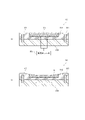
- Constant temperature chiller water 105 is supplied to the adsorbent 101 and the frame 102 to substantially reduce the temperature of the chuck table 100 during processing. It is known to maintain equality (see, for example, Patent Document 1).
- a work holding device for rotatably holding a work to be machined by a grindstone, comprising: a base; and a clamping member that is attached to the base with a gap between it and the chuck in the radial direction of the base and presses the peripheral edge of the chuck against the base.
- the clamping member provided on the base allows the base and the chuck to thermally expand independently while maintaining the state in which the peripheral edge of the chuck is pressed against the base. Even in the case where the base thermally expands to a large extent relative to the chuck, the workpiece can be machined with high accuracy without warping the attracting surface of the chuck.
- the work can be processed with high accuracy without warping the adsorption surface of the chuck. can.
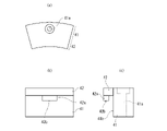
- FIG. 3 is a cross-sectional view taken along the line AA in FIG. 2 and a partially enlarged view; It is a figure which shows the structure of a clamp member, (a) is a top view, (b) is a front view, (c) is a side view.
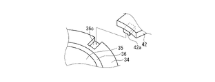
- FIG. 4 is a perspective view showing a mounting position of a clamp member with respect to a chuck table; 1A and 1B are diagrams showing a conventional chuck table and a base, in which FIG. 1A is a vertical cross-sectional view, and FIG.
- drawings may exaggerate by enlarging and exaggerating characteristic parts in order to make the features easier to understand, and the dimensional ratios, etc. of the constituent elements may not necessarily be the same as the actual ones.
- hatching of some components may be omitted in order to facilitate understanding of the cross-sectional structure of the components.
- expressions indicating directions such as up and down, left and right are not absolute, and are appropriate when each component is in the posture depicted in the drawing. In some cases, it should be changed and interpreted according to changes in posture.
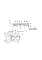
- the processing device 1 performs grinding processing on the workpiece W. As shown in FIG. 1, the processing device 1 includes a processing section 2 and a holding section 3 as a work holding device.
- the processing section 2 includes a grindstone 21 , a grindstone spindle 22 and an infeed mechanism 23 .
- the grindstone 21 is, for example, a cup-shaped grindstone and attached to the lower end of the grindstone spindle 22 .
- the grindstone spindle 22 is rotatable around the rotary shaft 2a, and the grindstone 21 and the grindstone spindle 22 are configured to be integrally rotatable.
- the infeed mechanism 23 raises and lowers the grindstone spindle 22 in the vertical direction.
- the infeed mechanism 23 has a known configuration, and is composed of, for example, a plurality of linear guides that guide the movement direction of the grindstone spindle 22 and a ball screw slider mechanism that moves the grindstone spindle 22 up and down.
- the infeed mechanism 23 is interposed between the grindstone spindle 22 and the column 24 .
- the holding unit 3 includes a chuck table 31 and a chuck spindle 32.
- the chuck table 31 includes a chuck 33 and a base 34.
- the chuck 33 includes an attracting body 35 and a frame body 36.
- the attracting body 35 is formed in a shape corresponding to the workpiece W when viewed from above.
- the adsorbent 35 is made of alumina porous material.
- the chuck table 31 has a conduit (not shown) extending through the inside to the surface.
- the pipeline is connected to a vacuum pump P and a compressed air source or water supply source (not shown) via a rotary joint (not shown).
- a vacuum pump P When the vacuum pump P is activated, a negative pressure is generated between the workpiece W placed on the adsorbent 35 and the upper surface (adsorption surface 35a) of the adsorption body 35, and the workpiece W is adsorbed and held on the adsorption surface 35a.
- the compressed air source or the water supply source is activated, the adsorption between the workpiece W and the adsorbent 35 is released.
- the frame 36 is made of a dense body of alumina with the adsorbent 35 embedded substantially in the center.
- a flange 36 a is formed on the outer periphery of the frame 36 .
- alumina is generally used for the adsorbent 35 and the frame 36, but any material that exhibits a lower thermal expansion coefficient than the base 34 may be used.
- Silicon carbide is lightweight and has excellent corrosion resistance and heat resistance. , or aluminum nitride or the like that exhibits good thermal conductivity.
- the base 34 is connected to the chuck spindle 32.
- a convex portion 34a provided in the center of the upper surface of the base 34 closely fits into a central concave portion 36b provided in the center of the lower surface of the frame 36, so that the center of the frame 36 and the center of the base 34 are aligned. ing.
- the base 34 is made of a material exhibiting a higher coefficient of thermal expansion than the adsorbent 35 and frame 36, such as stainless steel. Note that the thermal expansion coefficient of alumina is 7.2 ⁇ 10 ⁇ 6 /° C., and the thermal expansion coefficient of stainless steel (SUS304) is 17.3 ⁇ 10 ⁇ 6 /° C.
- the chuck table 31 has a clamp member 40 .
- the clamp member 40 has a main body portion 41 and an overhang portion 42 .
- the clamp member 40 is made of stainless steel, for example.
- the main body part 41 is formed in a substantially fan shape when viewed from the top.
- the body portion 41 is fastened to the base 34 via bolts B inserted through the bolt holes 41a.
- the projecting portion 42 is erected on the inner side surface 41b of the main body portion 41 .
- a detent projection 42a is provided on the lower surface of the projecting portion 42.
- the anti-rotation protrusion 42a is configured to fit into an outer peripheral recess 36c formed on the surface of the flange 36a.
- the anti-rotation protrusion 42a presses the flange 36a against the base 34 with the tightening force of the bolt B. Specifically, a clamped surface 36d facing the protruding portion 42 of the flange 36a is pressed toward the base 34 by a clamping surface 42b of the detent projection 42a facing the flange 36a.
- the anti-rotation protrusion 42a is offset with respect to the bolt B and is supported by the main body 41 in a cantilever manner, it is possible to prevent the fastening force of the bolt B from exerting an excessive clamping force on the flange 36a. do. Since the detent projection 42a moves relative to the chuck 33 due to thermal expansion of the base 34, which will be described later, the projection 42a is set to a size that allows contact with the flange 36a before and after movement.
- At least one of the lower surface 36e of the frame 36 and the upper surface 34b of the base 34 is preferably coated with a slippery layer (not shown) exhibiting low friction.
- the slippery layer is, for example, graphite, molybdenum disulfide, or DLC (diamond-like carbon).
- at least one of the frame 36 and the base 34 is preferably composed of graphite, molybdenum disulfide, DLC, or the like in which a solid lubricant is dispersed to exhibit low friction.
- At least one of the clamped surface 36d and the clamped surface 42b is preferably coated with a slippery layer (not shown) exhibiting low friction.
- the slippery layer is, for example, graphite, molybdenum disulfide, DLC, or the like.
- at least one of the frame 36 and the clamp member 40 is preferably made of graphite, molybdenum disulfide, DLC, or the like in which a solid lubricant is dispersed to exhibit low friction.
- gaps G1 and G2 are secured, respectively.
- the gaps G1 and G2 are set so that the clamp member 40 does not come into contact with the frame 36 in the radial direction D in the initial state before the base 34 expands in the radial direction D due to processing heat.
- the chuck spindle 32 is configured to rotationally drive the chuck table 31 around the rotary shaft 3a.
- a drive source for the chuck spindle 32 may be, for example, a servomotor.
- the operation of the processing device 1 is controlled by a control unit (not shown).
- the control unit controls each of the constituent elements that constitute the processing apparatus 1 .
- the control unit is composed of, for example, a CPU, a memory, and the like.
- the functions of the control unit may be realized by controlling using software, or may be realized by operating using hardware.
- the workpiece W is placed on the chuck 33 via a transfer robot or the like (not shown), and the vacuum pump P generates a negative pressure between the workpiece W and the attracting surface 35a, whereby the workpiece W is attracted to the attracting body 35. retained.
- the grindstone 21 is moved above the workpiece W by the slider of the infeed mechanism 23 .
- the work W is ground by pressing the grinding surface 21a of the grindstone 21 against the work W while rotating the grindstone 21 and the chuck 33, respectively.
- the rotation speed of the grindstone 21 is set to 2000 rpm
- the rotation speed of the workpiece W is set to 300 rpm. Since the detent projection 42 a fits into the outer peripheral recess 36 c to regulate the rotation of the chuck 33 in the radial direction D, the rotational drive of the chuck spindle 32 is transmitted to the chuck 33 .
- the base 34 and the chuck 33 are thermally expanded and deformed so as to expand in the radial direction D due to processing heat due to friction. Since the base 34 and the chuck 33 have different thermal expansion amounts, the base 34 thermally expands relatively more than the chuck 33 so that the upper surface 34b of the base 34 slides on the lower surface 36e of the frame 36 .
- the clamp member 40 presses the chuck 33 against the base 34 with gaps G1 and G2, thereby avoiding interference between the chuck 33 and the clamp member 40 when the chuck 33 and the base 34 thermally expand. can.
- the clamped surface 36d or the clamping surface 42b is coated with an easy-slip layer, or if at least one of the frame 36 or the clamping member 40 is made of a material exhibiting low friction, is easy for the clamp member 40 to move relative to the chuck 33 .
- the holding part 3 is a work holding device that rotatably holds the work W to be processed by the grindstone 21, and is composed of the base 34 and a material having a lower thermal expansion coefficient than the base 34
- a chuck 33 which is placed on a base 34 and is capable of holding the workpiece W by suction is attached to the base 34 with gaps G1 and G2 between the chuck 33 and the chuck 33 in the radial direction D of the base 34. and a clamp member 40 that presses the flange 36 a against the base 34 .
- the clamp member 40 provided on the base 34 can thermally expand the base 34 and the chuck 33 independently while maintaining the state in which the flange 36a is pressed against the base 34. Even if the base 34 thermally expands to a large extent relative to the chuck 33 due to the processing heat accompanying the processing of the work W, the work W is accurately processed without warping the adsorption surface 35a of the chuck 33. be able to.
- the holding portion 3 includes a detent projection 42a that the clamp member 40 is fitted to the outer peripheral recess 36c of the chuck 33 to restrict the rotation of the chuck 33 in the circumferential direction with respect to the base 34. It was configured with
- the rotation of the chuck 33 in the circumferential direction is restricted by fitting the anti-rotation protrusion 42a into the outer peripheral recess 36c, so that the workpiece W held by the chuck 33 can be ground with high accuracy. can do.
- clamping members 40 are provided on the outer periphery of the frame 36 at equal intervals, but the number of clamping members 40 installed is not less than seven but not less than nine. I don't mind.
- shape of the clamp member 40 is not limited to the one described above, and for example, it may be formed in an annular shape so as to surround the frame 36 .
- the clamping member 40 may omit the anti-rotation protrusion 42a, and the static friction of the force that presses the chuck 33 against the base 34 may be used.
- a configuration in which the chuck 33 is prevented from rotating in the circumferential direction only by force may be employed.
- the chuck 33 is made of a material having a lower coefficient of thermal expansion than the base 34, but the material of the chuck 33 is not limited to this.
- the chuck 33 thermally expands relatively greatly with respect to the base 34 due to processing heat accompanying processing of the work W.
- the clamping member 40 provided on the base 34 maintains the state of pressing the flange 36a against the base 34, and the base 34 and the chuck 33 are respectively clamped. Since it can be thermally expanded independently, the chucking surface 35a of the chuck 33 does not warp, and the workpiece W can be processed with high accuracy.
- the chuck 33 and the base 34 are made of materials exhibiting substantially equal coefficients of thermal expansion, more processing heat due to processing of the work W is transmitted to the chuck 33 than to the base 34 , and the chuck 33 is relative to the base 43 . may undergo large thermal expansion. Even in such a case, according to the configuration of the present invention, the clamping member 40 provided on the base 34 maintains the state of pressing the flange 36a against the base 34, and the base 34 and the chuck 33 are independently clamped. Since it is thermally expandable, the chucking surface 35a of the chuck 33 does not warp, and the workpiece W can be processed with high accuracy.
- Processing device 2 Processing unit 21: Grinding wheel 21a: Grinding surface 22: Grinding wheel spindle 23: In-feed mechanism 24: Column 3: Holding unit 31: Chuck table 32: Chuck spindle 33: Chuck 34: Base 34a: Convex portion 34b : Upper surface 35 (of the base) : Attractive body 35a : Attractive surface 36 : Frame 36a : Flange 36b : Central recess 36c : Peripheral recess 36d : Clamped surface 36e : Lower surface 36f (frame) : Periphery (frame) Surface 40 : Clamping member 41 : Main body 41a : Bolt hole 41b : Inner surface 42 (of main body) : Overhang 42a : Anti-rotation projection 42b : Clamp surface 42c : Inner peripheral surfaces G1 and G2 (of overhang) : Gap W: Work
Landscapes
- Engineering & Computer Science (AREA)
- Mechanical Engineering (AREA)
- Constituent Portions Of Griding Lathes, Driving, Sensing And Control (AREA)
- Grinding Of Cylindrical And Plane Surfaces (AREA)
- Mechanical Treatment Of Semiconductor (AREA)
- Container, Conveyance, Adherence, Positioning, Of Wafer (AREA)
Abstract
Description
2 :加工部
21 :砥石
21a :研削面
22 :砥石スピンドル
23 :インフィード機構
24 :コラム
3 :保持部
31 :チャックテーブル
32 :チャックスピンドル
33 :チャック
34 :ベース
34a :凸部
34b :(ベースの)上面
35 :吸着体
35a :吸着面
36 :枠体
36a :フランジ
36b :中央凹部
36c :外周凹部
36d :被クランプ面
36e :(枠体の)下面
36f :(枠体の)外周面
40 :クランプ部材
41 :本体部
41a :ボルト孔
41b :(本体部の)内側面
42 :張り出し部
42a :回り止め突部
42b :クランプ面
42c :(張り出し部の)内周面
G1、G2 :隙間
W :ワーク
Claims (6)
- 砥石で加工されるワークを回転可能に保持するワーク保持装置であって、
ベースと、
前記ベース上に載置され、前記ワークを吸着保持可能なチャックと、
前記ベースの径方向において前記チャックとの間に隙間を空けて前記ベースに取り付けられ、前記チャックの周縁を前記ベースに押さえつけるクランプ部材と、
を備えていることを特徴とするワーク保持装置。 - 前記ベースの前記チャックに対向する対向面又は前記チャックの前記ベースに対向する対向面の少なくとも一方には、前記チャックに対する前記ベースの横滑りを促す易滑り層が被膜されていることを特徴とする請求項1に記載のワーク保持装置。
- 前記ベース又は前記チャックの少なくとも一方は、前記チャックに対する前記ベースの横滑りを促す素材で構成されていることを特徴とする請求項1に記載のワーク保持装置。
- 前記チャックの前記クランプ部材に対向する被クランプ面又は前記クランプ部材の前記チャックに対向するクランプ面の少なくとも一方には、前記チャックに対する前記クランプ部材の横滑りを促す易滑り層が被膜されていることを特徴とする請求項1に記載のワーク保持装置。
- 前記チャック又は前記クランプ部材の少なくとも一方は、前記チャックに対する前記クランプ部材の横滑りを促す素材で構成されていることを特徴とする請求項1に記載のワーク保持装置。
- 前記クランプ部材は、前記チャックの凹部に嵌合されて、前記ベースに対する前記チャックの周方向の回転を規制する回り止め突部を備えていることを特徴とする請求項1乃至5の何れか1項に記載のワーク保持装置。
Priority Applications (3)
| Application Number | Priority Date | Filing Date | Title |
|---|---|---|---|
| CN202180096262.0A CN117042918B (zh) | 2021-03-23 | 2021-12-07 | 工件保持装置 |
| KR1020237029290A KR102772078B1 (ko) | 2021-03-23 | 2021-12-07 | 워크 유지 장치 |
| US18/281,936 US20240173817A1 (en) | 2021-03-23 | 2021-12-07 | Workpiece holding device |
Applications Claiming Priority (2)
| Application Number | Priority Date | Filing Date | Title |
|---|---|---|---|
| JP2021-048840 | 2021-03-23 | ||
| JP2021048840A JP7565842B2 (ja) | 2021-03-23 | 2021-03-23 | ワーク保持装置 |
Publications (1)
| Publication Number | Publication Date |
|---|---|
| WO2022201648A1 true WO2022201648A1 (ja) | 2022-09-29 |
Family
ID=83395296
Family Applications (1)
| Application Number | Title | Priority Date | Filing Date |
|---|---|---|---|
| PCT/JP2021/044819 Ceased WO2022201648A1 (ja) | 2021-03-23 | 2021-12-07 | ワーク保持装置 |
Country Status (5)
| Country | Link |
|---|---|
| US (1) | US20240173817A1 (ja) |
| JP (1) | JP7565842B2 (ja) |
| KR (1) | KR102772078B1 (ja) |
| CN (1) | CN117042918B (ja) |
| WO (1) | WO2022201648A1 (ja) |
Citations (9)
| Publication number | Priority date | Publication date | Assignee | Title |
|---|---|---|---|---|
| JPH06252253A (ja) * | 1993-02-26 | 1994-09-09 | Sumitomo Metal Ind Ltd | 静電チャック |
| JPH10102249A (ja) * | 1996-09-27 | 1998-04-21 | Nissin Electric Co Ltd | 基板保持装置 |
| JPH11145264A (ja) * | 1997-09-06 | 1999-05-28 | Anelva Corp | 静電吸着ステージ及びこの静電吸着ステージを備えた基板処理装置 |
| JP2005118979A (ja) * | 2003-09-22 | 2005-05-12 | Ibiden Co Ltd | 研削・研磨用真空チャックおよび吸着板 |
| JP2011222800A (ja) * | 2010-04-12 | 2011-11-04 | Disco Abrasive Syst Ltd | 保持テーブル |
| WO2013088733A1 (ja) * | 2011-12-14 | 2013-06-20 | 株式会社ニコン | 基板ホルダ及び一対の基板ホルダ |
| JP2014216496A (ja) * | 2013-04-25 | 2014-11-17 | 東京エレクトロン株式会社 | 接合装置、接合システムおよび接合方法 |
| JP2018050039A (ja) * | 2016-09-20 | 2018-03-29 | 日本碍子株式会社 | ウエハ載置装置 |
| JP2020057696A (ja) * | 2018-10-02 | 2020-04-09 | 東京エレクトロン株式会社 | プラズマ処理装置及び静電吸着方法 |
Family Cites Families (7)
| Publication number | Priority date | Publication date | Assignee | Title |
|---|---|---|---|---|
| JP2000288857A (ja) * | 1999-03-31 | 2000-10-17 | Shibaura Mechatronics Corp | 静電チャック装置及び載置台 |
| JP5482282B2 (ja) * | 2009-03-03 | 2014-05-07 | 東京エレクトロン株式会社 | 載置台構造及び成膜装置 |
| JP2017069429A (ja) | 2015-09-30 | 2017-04-06 | 株式会社東京精密 | ウェハの高精度加工装置 |
| CN205310048U (zh) * | 2015-12-30 | 2016-06-15 | 株洲中航动科南方燃气轮机成套制造安装有限公司 | 磨工夹具 |
| JP6696851B2 (ja) * | 2016-07-13 | 2020-05-20 | 株式会社ディスコ | チャックテーブル機構 |
| CN111801787B (zh) * | 2018-09-13 | 2023-10-03 | 日本碍子株式会社 | 晶圆载置装置 |
| JP7228989B2 (ja) * | 2018-11-05 | 2023-02-27 | 東京エレクトロン株式会社 | 載置台、エッジリングの位置決め方法及び基板処理装置 |
-
2021
- 2021-03-23 JP JP2021048840A patent/JP7565842B2/ja active Active
- 2021-12-07 CN CN202180096262.0A patent/CN117042918B/zh active Active
- 2021-12-07 KR KR1020237029290A patent/KR102772078B1/ko active Active
- 2021-12-07 WO PCT/JP2021/044819 patent/WO2022201648A1/ja not_active Ceased
- 2021-12-07 US US18/281,936 patent/US20240173817A1/en active Pending
Patent Citations (9)
| Publication number | Priority date | Publication date | Assignee | Title |
|---|---|---|---|---|
| JPH06252253A (ja) * | 1993-02-26 | 1994-09-09 | Sumitomo Metal Ind Ltd | 静電チャック |
| JPH10102249A (ja) * | 1996-09-27 | 1998-04-21 | Nissin Electric Co Ltd | 基板保持装置 |
| JPH11145264A (ja) * | 1997-09-06 | 1999-05-28 | Anelva Corp | 静電吸着ステージ及びこの静電吸着ステージを備えた基板処理装置 |
| JP2005118979A (ja) * | 2003-09-22 | 2005-05-12 | Ibiden Co Ltd | 研削・研磨用真空チャックおよび吸着板 |
| JP2011222800A (ja) * | 2010-04-12 | 2011-11-04 | Disco Abrasive Syst Ltd | 保持テーブル |
| WO2013088733A1 (ja) * | 2011-12-14 | 2013-06-20 | 株式会社ニコン | 基板ホルダ及び一対の基板ホルダ |
| JP2014216496A (ja) * | 2013-04-25 | 2014-11-17 | 東京エレクトロン株式会社 | 接合装置、接合システムおよび接合方法 |
| JP2018050039A (ja) * | 2016-09-20 | 2018-03-29 | 日本碍子株式会社 | ウエハ載置装置 |
| JP2020057696A (ja) * | 2018-10-02 | 2020-04-09 | 東京エレクトロン株式会社 | プラズマ処理装置及び静電吸着方法 |
Also Published As
| Publication number | Publication date |
|---|---|
| JP7565842B2 (ja) | 2024-10-11 |
| JP2022147550A (ja) | 2022-10-06 |
| KR102772078B1 (ko) | 2025-02-21 |
| US20240173817A1 (en) | 2024-05-30 |
| KR20230132596A (ko) | 2023-09-15 |
| CN117042918B (zh) | 2025-08-22 |
| CN117042918A (zh) | 2023-11-10 |
Similar Documents
| Publication | Publication Date | Title |
|---|---|---|
| CN100429041C (zh) | 换位工作台 | |
| US8448543B2 (en) | Clamping device for rotary index device for machine tool | |
| US8505895B2 (en) | Clamping device in main shaft driving device for machine tool | |
| JP5117260B2 (ja) | 工作機械における主軸駆動装置の回転抵抗装置 | |
| JP5078526B2 (ja) | 工作機械用の回転割出し装置のためのクランプ装置 | |
| CN101801594A (zh) | 工作机械用的旋转分度盘装置 | |
| JP6524596B2 (ja) | 予圧の調整のための軸受の可変予圧システム | |
| WO2022201648A1 (ja) | ワーク保持装置 | |
| KR20210155713A (ko) | 인덱스 테이블용 원형가공 회전장치 | |
| US10335908B2 (en) | Rotary table device | |
| JP2006167821A (ja) | 装着物の取り付け方法及びスピンドル装置 | |
| KR101854647B1 (ko) | 에어베어링을 이용한 흡착 또는 비접촉 부상 구조를 갖는 진공회전 테이블 | |
| JP2025072601A (ja) | 加工装置 | |
| JP2012187648A (ja) | ワーク内面の研削方法 | |
| CN214092763U (zh) | 一种真空吸盘夹紧主轴排气结构及晶圆减薄机 | |
| CN214063587U (zh) | 一种真空吸盘夹紧主轴注油结构及晶圆减薄机 | |
| JPS58217201A (ja) | 円筒体の端面加工装置 | |
| JP7114862B2 (ja) | ワーク保持装置及びワーク加工方法 | |
| CN223160743U (zh) | 保温杯抛光夹具 | |
| JPS63191535A (ja) | 薄板加工装置 | |
| KR101392149B1 (ko) | 폴리싱 헤드 | |
| JPH06143249A (ja) | スライシングマシンにおけるブレードクランプ装置 | |
| KR20190001825A (ko) | 공작기계 주축의 클램프 장치 | |
| JP2023159658A (ja) | 回転軸クランプ装置 | |
| JPH0329537B2 (ja) |
Legal Events
| Date | Code | Title | Description |
|---|---|---|---|
| 121 | Ep: the epo has been informed by wipo that ep was designated in this application |
Ref document number: 21931955 Country of ref document: EP Kind code of ref document: A1 |
|
| ENP | Entry into the national phase |
Ref document number: 20237029290 Country of ref document: KR Kind code of ref document: A |
|
| WWE | Wipo information: entry into national phase |
Ref document number: 1020237029290 Country of ref document: KR |
|
| WWE | Wipo information: entry into national phase |
Ref document number: 18281936 Country of ref document: US |
|
| WWE | Wipo information: entry into national phase |
Ref document number: 202180096262.0 Country of ref document: CN |
|
| NENP | Non-entry into the national phase |
Ref country code: DE |
|
| 122 | Ep: pct application non-entry in european phase |
Ref document number: 21931955 Country of ref document: EP Kind code of ref document: A1 |
|
| WWG | Wipo information: grant in national office |
Ref document number: 1020237029290 Country of ref document: KR |
|
| WWG | Wipo information: grant in national office |
Ref document number: 202180096262.0 Country of ref document: CN |