WO2022196367A1 - フレーム構造 - Google Patents
フレーム構造 Download PDFInfo
- Publication number
- WO2022196367A1 WO2022196367A1 PCT/JP2022/009027 JP2022009027W WO2022196367A1 WO 2022196367 A1 WO2022196367 A1 WO 2022196367A1 JP 2022009027 W JP2022009027 W JP 2022009027W WO 2022196367 A1 WO2022196367 A1 WO 2022196367A1
- Authority
- WO
- WIPO (PCT)
- Prior art keywords
- hole
- intermediate member
- side member
- vehicle
- longitudinal direction
- Prior art date
- Legal status (The legal status is an assumption and is not a legal conclusion. Google has not performed a legal analysis and makes no representation as to the accuracy of the status listed.)
- Ceased
Links
Images



Classifications
-
- B—PERFORMING OPERATIONS; TRANSPORTING
- B62—LAND VEHICLES FOR TRAVELLING OTHERWISE THAN ON RAILS
- B62D—MOTOR VEHICLES; TRAILERS
- B62D21/00—Understructures, i.e. chassis frame on which a vehicle body may be mounted
- B62D21/07—Understructures, i.e. chassis frame on which a vehicle body may be mounted wide-hipped frame type, i.e. a wide box-shaped mid portion with narrower sections extending from said mid portion in both fore and aft directions
-
- B—PERFORMING OPERATIONS; TRANSPORTING
- B62—LAND VEHICLES FOR TRAVELLING OTHERWISE THAN ON RAILS
- B62D—MOTOR VEHICLES; TRAILERS
- B62D21/00—Understructures, i.e. chassis frame on which a vehicle body may be mounted
- B62D21/02—Understructures, i.e. chassis frame on which a vehicle body may be mounted comprising longitudinally or transversely arranged frame members
-
- B—PERFORMING OPERATIONS; TRANSPORTING
- B62—LAND VEHICLES FOR TRAVELLING OTHERWISE THAN ON RAILS
- B62D—MOTOR VEHICLES; TRAILERS
- B62D27/00—Connections between superstructure or understructure sub-units
- B62D27/02—Connections between superstructure or understructure sub-units rigid
- B62D27/023—Assembly of structural joints
Definitions
- the present invention relates to a vehicle frame structure.
- Patent Literature 1 discloses a frame structure in which the distance between two side frames in one region in the longitudinal direction of the vehicle is different from the distance in other regions.
- an object of the present invention is to increase the distance between a plurality of side frames in a partial area of a vehicle while ensuring sufficient strength. .
- a frame structure of the present invention is a frame structure for a vehicle, and has four or more front through-holes, and a front intermediate member provided such that its longitudinal direction coincides with the width direction of the vehicle;
- a rear intermediate member having one or more rear through-holes and provided behind the front intermediate member such that its longitudinal direction coincides with the width direction of the vehicle;
- the first front side member extending forward of the front intermediate member and the second front through hole of the front intermediate member are fixed while being inserted into the through hole.
- a second front side member extending forward of the front intermediate member and a first rear through-hole of the rear intermediate member, the first side member extending rearward of the rear intermediate member being inserted into and fixed to a first rear through hole of the rear intermediate member;
- a rear side member a second rear side member fixed in a state of being inserted into a second rear through hole of the rear intermediate member and extending rearward of the rear intermediate member, the front intermediate member and the rear
- intermediate members a first intermediate side member inserted and fixed in a third front through-hole of the front intermediate member and a third rear through-hole of the rear intermediate member; and the front intermediate member.
- the position of the first front through hole in the longitudinal direction of the front intermediate member and the position of the first rear through hole in the longitudinal direction of the rear intermediate member are the same, and the position of the first rear through hole in the longitudinal direction of the front intermediate member is the same.
- the position of the two front through-holes and the position of the second rear through-hole in the longitudinal direction of the rear intermediate member may be the same.
- the longitudinal extension of the first front side member and the longitudinal extension of the first rear side member coincide, and the longitudinal extension of the second front side member and the longitudinal extension of the second rear side member are aligned. It may coincide with the extension line in the longitudinal direction.
- the position of the third front through hole in the longitudinal direction of the front intermediate member and the position of the third rear through hole in the longitudinal direction of the rear intermediate member are the same, and the position of the third rear through hole in the longitudinal direction of the front intermediate member is the same. 4. Even if the position of the front through-hole is the same as the position of the fourth rear through-hole in the longitudinal direction of the rear intermediate member, and the first intermediate side member and the second intermediate side member are parallel to each other. good.
- the positions of the first front through hole and the second front through hole in the longitudinal direction of the front intermediate member are higher than the positions of the third front through hole and the fourth front through hole in the longitudinal direction of the front intermediate member. It may be inside the vehicle.
- the position of the first front through-hole and the position of the first rear through-hole in the height direction of the vehicle are different, and the position of the second front through-hole and the second rear through-hole in the height direction of the vehicle are different.
- the positions of the through holes are different from each other, the positions of the third front through hole and the third rear through hole in the height direction of the vehicle are the same, and the positions of the fourth front through hole in the height direction of the vehicle are the same; and the position of the fourth rear through-hole may be the same.
- the first intermediate side member has a first reinforcing member provided at least either above or below the linear first basic member
- the second intermediate side member is a linear second basic member. and further comprising a second reinforcing member provided at least either above or below the front intermediate member and the rear intermediate member in the region between the front intermediate member and the rear intermediate member.
- the width of the intermediate side member and the width of the second intermediate side member are equal to the width of the first intermediate side member and the width of the second intermediate side member in the vehicle height direction in the regions forward of the front intermediate member and rearward of the rear intermediate member. It may be larger than the width of the two intermediate side members.
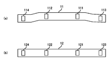
- FIG. 1 is a perspective view of a frame structure
- FIG. FIG. 4 is a plan view of the front intermediate member and the rear intermediate member as seen from the front-rear direction of the vehicle
- FIG. 1 is a diagram showing an outline of a frame structure 1 mounted on a vehicle.
- FIG. 2 is a perspective view of the frame structure 1.
- the vehicle is for example a commercial vehicle.
- FIG. 1 is a schematic diagram showing a frame structure 1 viewed from above a vehicle. The frame structure 1 is provided at a position that does not interfere with the wheels W.
- the frame structure 1 includes a front intermediate member 11, a rear intermediate member 12, a first front side member 13, a second front side member 14, and a first rear side member 15. , a second rear side member 16 , a first intermediate side member 17 and a second intermediate side member 18 .
- the front intermediate member 11 has four or more front through-holes, and is provided such that its longitudinal direction coincides with the vehicle width direction (that is, the left-right direction).
- the rear intermediate member 12 has four or more rear through-holes, and is provided behind the front intermediate member 11 so that its longitudinal direction coincides with the width direction of the vehicle.
- FIG. 3 is a plan view of the front intermediate member 11 and the rear intermediate member 12 as seen from the rear of the vehicle.
- the number of front through-holes in the front intermediate member 11 and the number of rear through-holes in the rear intermediate member 12 are arbitrary, but in the example shown in FIG. 3, four front through-holes and four rear through-holes are provided.
- the front intermediate member 11 has a first front through-hole 111 , a second front through-hole 112 , a third front through-hole 113 and a fourth front through-hole 114 .
- the rear intermediate member 12 has a first rear through-hole 121 , a second rear through-hole 122 , a third rear through-hole 123 and a fourth rear through-hole 124 .
- the shape of the front through-hole and the rear through-hole is a shape equivalent to the cross-sectional shape of the side member to be inserted, and a shape larger than the cross-sectional shape of the side member.
- the through-hole is rectangular in size so that the first front side member 13, the second front side member 14, the first rear side member 15 and the second rear side member 16 can be inserted.
- the first front side member 13 is fixed to the front intermediate member 11 by a gusset 21 while being inserted into the first front through hole 111 of the front intermediate member 11, and extends from the front intermediate member 11 to the front of the vehicle. ing.
- the second front side member 14 is fixed to the front intermediate member 11 by a gusset 21 while being inserted into the second front through hole 112 of the front intermediate member 11, and extends forward of the vehicle from the front intermediate member 11.
- the first front side member 13 and the second front side member 14 are parallel to the longitudinal direction of the vehicle, but the first front side member 13 and the second front side member 14 are parallel to the longitudinal direction of the vehicle. may not be parallel to
- the first rear side member 15 is fixed to the rear intermediate member 12 by a gusset 21 while being inserted into a first rear through hole 121 of the rear intermediate member 12, and extends rearward of the vehicle from the rear intermediate member 12.
- the second rear side member 16 is fixed to the rear intermediate member 12 by a gusset 21 while being inserted into a second rear through hole of the rear intermediate member 12, and extends rearward of the vehicle from the rear intermediate member 12. .
- the first intermediate side member 17 is inserted into the third front through hole 113 of the front intermediate member 11 and the third rear through hole 123 of the rear intermediate member 12 between the front intermediate member 11 and the rear intermediate member 12. In this state, it is fixed to the front intermediate member 11 and the rear intermediate member 12 by gussets 21 .
- the second intermediate side member 18 is inserted into the fourth front through hole 114 of the front intermediate member 11 and the fourth rear through hole 124 of the rear intermediate member 12 between the front intermediate member 11 and the rear intermediate member 12. In this state, it is fixed to the front intermediate member 11 and the rear intermediate member 12 by gussets 21 .
- the first front through-hole 111 and the second front through-hole 112 are formed inside the third front through-hole 113 and the fourth front through-hole 114, and the first rear through-hole 121 and the fourth front through-hole 114 are formed inside.
- the second rear through-hole 122 is provided inside the third rear through-hole 123 and the fourth rear through-hole 124 .
- the distance between the first intermediate side member 17 and the second intermediate side member 18 is equal to the distance between the first front side member 13 and the second front side member 14 and the distance between the first rear side member 15 and the distance between the first front side member 13 and the second front side member 14. and the second rear side member 16.
- the size of the area surrounded by the front intermediate member 11, the rear intermediate member 12, the first intermediate side member 17 and the second intermediate side member 18 is the size of the first intermediate side member 17 and the second intermediate side member 18.
- the spacing is greater than the spacing between the first front side member 13 and the second front side member 14 and the spacing between the first rear side member 15 and the second rear side member 16 .
- Each side member is connected to either the front intermediate member 11 or the rear intermediate member 12 by a gusset 21 while being inserted into the front through hole or the rear through hole. Since the frame structure 1 is configured in this manner, the side members can be easily aligned by inserting them into the front through-holes or the rear through-holes, so that the side members can be welded to the front intermediate member 11 and the rear through-hole.
- the frame structure 1 can be easily manufactured without using a special jig, as compared with the case of coupling with the rear intermediate member 12 .
- the position of the first front through hole 111 in the longitudinal direction of the front intermediate member 11 (that is, the width direction of the vehicle) and the position of the first front through hole 111 in the longitudinal direction of the rear intermediate member 12 (that is, the width direction of the vehicle).
- the position of the rear through hole 121 is the same.
- the position of the second front through hole 112 in the longitudinal direction of the front intermediate member 11 and the position of the second rear through hole 122 in the longitudinal direction of the rear intermediate member 12 are the same.
- the front intermediate member 11 and the rear intermediate member 12 By configuring the front intermediate member 11 and the rear intermediate member 12 in this way, the longitudinal extension of the first front side member 13 and the longitudinal extension of the first rear side member 15 are aligned, The longitudinal extension of the second front side member 14 and the longitudinal extension of the second rear side member 16 coincide.
- the first front side member 13 and the second front side member 14 are provided inside the two front wheels, and the first rear side member 15 and the second rear side member 16 are provided on the two rear wheels. It is suitable when provided inside.
- the position of the first front through-hole 111 and the position of the first rear through-hole 121 in the width direction of the vehicle are different, and the position of the second front through-hole 112 and the position of the second rear through-hole 122 are different.
- Such a configuration is suitable when it is necessary to vary the distance between the side frames in the front and rear of the vehicle.
- the position of the third front through-hole 113 in the longitudinal direction of the front intermediate member 11 and the position of the third rear through-hole 123 in the longitudinal direction of the rear intermediate member 12 are the same.
- the position of the fourth front through hole 114 in the longitudinal direction of the front intermediate member 11 and the position of the fourth rear through hole 124 in the longitudinal direction of the rear intermediate member 12 are the same.
- the first intermediate side member 17 and the second intermediate side member 18 are parallel to each other, as shown in FIG.
- the positions of the first front through-hole 111 and the second front through-hole 112 in the longitudinal direction of the front intermediate member 11 are the positions of the third front through-hole 113 and the fourth front through-hole 113 in the longitudinal direction of the front intermediate member 11 . It is inside the vehicle from the position of the front through hole 114 .
- the positions of the first rear through-hole 121 and the second rear through-hole 122 in the longitudinal direction of the rear intermediate member 12 are the positions of the third rear through-hole 123 and the fourth rear through-hole 124 in the longitudinal direction of the rear intermediate member 12.
- the distance between the side members near the center of the vehicle can be made larger than the distance between the side members at the front and rear of the vehicle.
- Such a configuration is suitable for increasing the width of the cargo bed near the center of the vehicle and increasing the allowable load on both sides of the cargo bed near the center of the vehicle.
- the height of the first front side member 13 and the second front side member 14 and the height of the first rear side member 15 and the second rear side member 16 may be different.
- the position of the first front through hole 111 and the position of the first rear through hole 121 in the height direction of the vehicle are different, and the position of the second front through hole 112 and the position of the second front through hole 112 in the height direction of the vehicle are different.
- the position of the rear through hole 122 may be different.
- the positions of the third front through-hole 113 and the third rear through-hole 123 in the height direction of the vehicle are the same, and the positions of the fourth front through-hole 114 and the fourth rear through-hole 124 in the height direction of the vehicle are the same. They may be identical.
- Such a configuration of the frame structure 1 is suitable when it is necessary to secure a large space for housing equipment under the side frames either in front of the front intermediate member 11 or behind the rear intermediate member 12.
- the height of the position where the front intermediate member 11 is joined to the first front side member 13 and the second front side member 14 is the height of the first intermediate side member 17 and the second intermediate side member 18. It is above the height of the position to be joined.
- the front intermediate member 11 is configured so that the vicinity of the center thereof is higher than the vicinity of both ends thereof, compared with the case where the front intermediate member 11 is configured in a straight line, the first front side member 13 and the second front side member 13 are more likely to move.
- a space for accommodating equipment can be increased under the two front side members 14 .
- the member 18 may be composed of a primary member and a reinforcing member.
- the first intermediate side member 17 has a first reinforcing member 172 and a first reinforcing member 173 provided at least either above or below the linear first base member 171.
- the second intermediate side member 18 has a second reinforcing member 182 and a second reinforcing member 183 provided at least either above or below the linear second basic member 181 .
- the width of the first intermediate side member 17 and the width of the second intermediate side member 18 in the height direction of the vehicle in the region between the front intermediate member 11 and the rear intermediate member 12 are the front and rear of the front intermediate member 11. It is greater than the width of the first intermediate side member 17 and the width of the second intermediate side member 18 in the vehicle height direction in the region behind the intermediate member 12 .
- FIG. 4 is a diagram showing a configuration of a modified example of the second intermediate side member 18. As shown in FIG. FIG. 4(a) is a diagram showing a state where the periphery of the connecting portion between the front intermediate member 11 and the second intermediate side member 18 is viewed from the left side of the vehicle. FIG. 4(b) is a sectional view taken along line AA.
- a second reinforcing member 182 is provided to cover the upper end of the second basic member 181
- a second reinforcing member 182 is provided to cover the lower end of the second basic member 181
- a member 183 is provided.
- the cross sections of the second reinforcing member 182 and the second reinforcing member 183 are U-shaped.
- the second reinforcing member 182 passes through the front intermediate member 11 while covering the second basic member 181, and is coupled with the front intermediate member 11 by being tightened together with the gusset 21 by the bolt B.
- the second reinforcing member 183 penetrates the front intermediate member 11 while covering the second basic member 181, and is fastened together with the gusset 21 and the second basic member 181 by bolts B, thereby connecting the front intermediate member 11 with the second reinforcing member 183.
- the second reinforcing member 183 has a width in the height direction in the region behind the front intermediate member 11 larger than the width in the height direction in the region in front of the front intermediate member 11 . That is, in the area behind the front intermediate member 11 , the lower end of the second reinforcing member 183 is below the lower end of the through hole formed in the front intermediate member 11 .
- the width H in the height direction of the region behind the front intermediate member 11 of the member obtained by coupling the second basic member 181, the second reinforcing member 182, and the second reinforcing member 183 is It is larger than the width h in the height direction in the front area of the intermediate member 11 .
- the width in the height direction of the side frame in the region between the front intermediate member 11 and the rear intermediate member 12 is greater than the width in the height direction of the side frame in the example shown in FIG.
- the strength in the height direction in the region between the front intermediate member 11 and the rear intermediate member 12 can be increased.
- the second reinforcing member 183 is configured such that the width in the height direction is maximized at the position where it is joined to the gusset 21 by the bolt B. By configuring the second reinforcing member 183 in this way, it is possible to increase the strength of the portion where the second reinforcing member 183 is coupled to the second base member 181 and to reduce the weight.
- FIG. 4 illustrates the case where the second intermediate side member 18 has the second reinforcing member 182 and the second reinforcing member 183, the second intermediate side member 18 may be the second reinforcing member 182 or the second reinforcing member. 183 only.
- FIG. 3 illustrates the case where the front intermediate member 11 and the rear intermediate member 12 have four through holes
- the number of through holes that the front intermediate member 11 and the rear intermediate member 12 have is Optional.
- the distance between the first front side member 13 and the second front side member 14 and the distance between the first rear side member 15 and the second rear side member are reduced.
- the degree of freedom of the interval with 16 increases.
- a vehicle with a different spacing between the first front side member 13 and the second front side member 14 or a spacing between the first rear side member 15 and the second rear side member 16 can be provided with a common front intermediate member. Since it can be manufactured using the member 11 and the rear intermediate member 12, manufacturing efficiency and manufacturing cost can be reduced.
- the front intermediate member 11 is not linear, and the positions of the first front through-hole 111 and the second front through-hole 112 in the height direction of the vehicle are different from the third front through-hole 113 and the third front through-hole 113 . 4 above the position of the front through-hole 114 .
- the forward intermediate member 11 may be straight like the rear intermediate member 12 .
- the rear intermediate member 12 may be configured such that some of the rear through-holes are positioned higher than the other rear through-holes, like the front intermediate member 11 shown in FIG.
- the front intermediate member 11 and the rear intermediate member 12 may be linear, and the height of some through holes may be different from that of other through holes.
- first intermediate side member 17 and the second intermediate side member 18 inserted into two of the other through holes of the front intermediate member 11 and the rear intermediate member 12, the front intermediate member 11 and the rear intermediate member 11 are separated from each other.
- a first intermediate side member 17 and a second intermediate side member 18 are provided between the members 12 .
- the space between the side frames in the midway region in the front-rear direction of the vehicle can be adjusted by using the frames that are linear when viewed from above.
- the spacing between frames can be different. That is, it is possible to increase the distance between the plurality of side frames in a partial area of the vehicle while sufficiently ensuring the strength in the longitudinal direction and the width direction of the vehicle. As a result, it is possible to secure a sufficient space for installing equipment on the side of the side frame.
- first front side member 13, the second front side member 14, the first rear side member 15, the second rear side member 16, the first intermediate side member 17 and the second intermediate side member 18 are the front intermediate member 11 and the second intermediate side member 18. After being inserted into the through hole of the rear intermediate member 12 , it is fixed by the gusset 21 . Therefore, an assembling jig that is necessary when joining these members by welding is not required, and mass productivity can be improved.
Landscapes
- Engineering & Computer Science (AREA)
- Chemical & Material Sciences (AREA)
- Combustion & Propulsion (AREA)
- Transportation (AREA)
- Mechanical Engineering (AREA)
- Body Structure For Vehicles (AREA)
Abstract
Description
図1は、車両に搭載されたフレーム構造1の概要を示す図である。図2は、フレーム構造1の斜視図である。車両は、例えば商用車である。図1は、車両の上方からフレーム構造1を見た状態を示す模式図である。フレーム構造1は、車輪Wと干渉しない位置に設けられている。
以上の説明においては、第1中間サイドメンバー17及び第2中間サイドメンバー18が、閉断面を有する一つの部材により構成されている場合を例示したが、第1中間サイドメンバー17及び第2中間サイドメンバー18が、基本部材と補強部材により構成されていてもよい。
図3に示した例においては、前方中間メンバー11及び後方中間メンバー12が4つの貫通孔を有している場合を例示したが、前方中間メンバー11及び後方中間メンバー12が有する貫通孔の数は任意である。前方中間メンバー11及び後方中間メンバー12がより多くの貫通孔を有することで、第1前方サイドメンバー13と第2前方サイドメンバー14との間隔、及び第1後方サイドメンバー15と第2後方サイドメンバー16との間隔の自由度が増す。その結果、第1前方サイドメンバー13と第2前方サイドメンバー14との間隔、又は第1後方サイドメンバー15と第2後方サイドメンバー16との間隔の少なくともいずれかが異なる車両を、共通の前方中間メンバー11及び後方中間メンバー12を用いて製造することができるので、製造効率及び製造コストを削減することが可能になる。
図3に示した例においては、前方中間メンバー11が直線状ではなく、車両の高さ方向における第1前方貫通孔111及び第2前方貫通孔112の位置が、第3前方貫通孔113及び第4前方貫通孔114の位置よりも上方にあった。しかし、前方中間メンバー11は、後方中間メンバー12と同様に直線状であってもよい。また、後方中間メンバー12が、図3に示した前方中間メンバー11のように、一部の後方貫通孔が他の後方貫通孔よりも高い位置になるように構成されていてもよい。また、前方中間メンバー11及び後方中間メンバー12が直線状で、一部の貫通孔の位置の高さが他の貫通孔の位置と異なるように構成されていてもよい。
以上説明したように、フレーム構造1においては、4つ以上の貫通孔を有する前方中間メンバー11の2つの貫通孔に第1前方サイドメンバー13及び第2前方サイドメンバー14が挿入された状態で、前方中間メンバー11の前方に第1前方サイドメンバー13及び第2前方サイドメンバー14が設けられている。また、4つ以上の貫通孔を有する後方中間メンバー12の2つの貫通孔に第1後方サイドメンバー15及び第2後方サイドメンバー16が挿入された状態で、前方中間メンバー11の後方に第1後方サイドメンバー15及び第2後方サイドメンバー16が設けられている。そして、前方中間メンバー11及び後方中間メンバー12の他の貫通孔のうち2つの貫通孔に第1中間サイドメンバー17及び第2中間サイドメンバー18が挿入された状態で、前方中間メンバー11と後方中間メンバー12との間に第1中間サイドメンバー17及び第2中間サイドメンバー18が設けられている。
11 前方中間メンバー
12 後方中間メンバー
13 第1前方サイドメンバー
14 第2前方サイドメンバー
15 第1後方サイドメンバー
16 第2後方サイドメンバー
17 第1中間サイドメンバー
18 第2中間サイドメンバー
21 ガセット
111 第1前方貫通孔
112 第2前方貫通孔
113 第3前方貫通孔
114 第4前方貫通孔
121 第1後方貫通孔
122 第2後方貫通孔
123 第3後方貫通孔
124 第4後方貫通孔
171 第1基本部材
172 第1補強部材
173 第1補強部材
181 第2基本部材
182 第2補強部材
183 第2補強部材
Claims (7)
- 車両のフレーム構造であって、
4つ以上の前方貫通孔を有しており、長手方向が前記車両の幅方向と一致するように設けられた前方中間メンバーと、
4つ以上の後方貫通孔を有しており、長手方向が前記車両の幅方向と一致するように、前記前方中間メンバーの後方に設けられた後方中間メンバーと、
前記前方中間メンバーが有する第1前方貫通孔に挿入された状態で固定されており、前記前方中間メンバーの前方に延びた第1前方サイドメンバーと、
前記前方中間メンバーが有する第2前方貫通孔に挿入された状態で固定されており、前記前方中間メンバーの前方に延びた第2前方サイドメンバーと、
前記後方中間メンバーが有する第1後方貫通孔に挿入された状態で固定されており、前記後方中間メンバーの後方に延びた第1後方サイドメンバーと、
前記後方中間メンバーが有する第2後方貫通孔に挿入された状態で固定されており、前記後方中間メンバーの後方に延びた第2後方サイドメンバーと、
前記前方中間メンバーと前記後方中間メンバーの間において、前記前方中間メンバーが有する第3前方貫通孔と前記後方中間メンバーが有する第3後方貫通孔とに挿入された状態で固定されている第1中間サイドメンバーと、
前記前方中間メンバーと前記後方中間メンバーの間において、前記前方中間メンバーが有する第4前方貫通孔と前記後方中間メンバーが有する第4後方貫通孔とに挿入された状態で固定されている第2中間サイドメンバーと、
を有するフレーム構造。 - 前記前方中間メンバーの長手方向における前記第1前方貫通孔の位置と、前記後方中間メンバーの長手方向における前記第1後方貫通孔の位置とが同一であり、
前記前方中間メンバーの長手方向における前記第2前方貫通孔の位置と、前記後方中間メンバーの長手方向における前記第2後方貫通孔の位置とが同一である、
請求項1に記載のフレーム構造。 - 前記第1前方サイドメンバーの長手方向の延長線と前記第1後方サイドメンバーの長手方向の延長線とが一致し、前記第2前方サイドメンバーの長手方向の延長線と前記第2後方サイドメンバーの長手方向の延長線とが一致する、
請求項2に記載のフレーム構造。 - 前記前方中間メンバーの長手方向における前記第3前方貫通孔の位置と、前記後方中間メンバーの長手方向における前記第3後方貫通孔の位置とが同一であり、
前記前方中間メンバーの長手方向における前記第4前方貫通孔の位置と、前記後方中間メンバーの長手方向における前記第4後方貫通孔の位置とが同一であり、
前記第1中間サイドメンバーと前記第2中間サイドメンバーが互いに平行である、
請求項1から3のいずれか一項に記載のフレーム構造。 - 前記前方中間メンバーの長手方向における前記第1前方貫通孔及び前記第2前方貫通孔の位置が、前記前方中間メンバーの長手方向における前記第3前方貫通孔及び前記第4前方貫通孔の位置よりも前記車両の内側である、
請求項1から4のいずれか一項に記載のフレーム構造。 - 前記車両の高さ方向における前記第1前方貫通孔の位置と前記第1後方貫通孔の位置とが異なっており、
前記車両の高さ方向における前記第2前方貫通孔の位置と前記第2後方貫通孔の位置とが異なっており、
前記車両の高さ方向における前記第3前方貫通孔と前記第3後方貫通孔の位置が同一であり、
前記車両の高さ方向における前記第4前方貫通孔と前記第4後方貫通孔の位置が同一である、
請求項1から5のいずれか一項に記載のフレーム構造。 - 前記第1中間サイドメンバーは、直線状の第1基本部材の上方又は下方の少なくともいずれかに設けられた第1補強部材を有し、
前記第2中間サイドメンバーは、直線状の第2基本部材の上方又は下方の少なくともいずれかに設けられた第2補強部材を有し、
をさらに有し、
前記前方中間メンバーと前記後方中間メンバーとの間の領域における前記車両の高さ方向の前記第1中間サイドメンバーの幅及び前記第2中間サイドメンバーの幅が、前記前方中間メンバーの前方及び前記後方中間メンバーの後方の領域における前記車両の高さ方向の前記第1中間サイドメンバーの幅及び前記第2中間サイドメンバーの幅よりも大きい、
請求項1から6のいずれか一項に記載のフレーム構造。
Priority Applications (3)
| Application Number | Priority Date | Filing Date | Title |
|---|---|---|---|
| DE112022001494.6T DE112022001494T5 (de) | 2021-03-16 | 2022-03-03 | Rahmenstruktur |
| CN202280015994.7A CN116917193A (zh) | 2021-03-16 | 2022-03-03 | 框架结构 |
| US18/550,785 US20240190504A1 (en) | 2021-03-16 | 2022-03-03 | Frame structure |
Applications Claiming Priority (2)
| Application Number | Priority Date | Filing Date | Title |
|---|---|---|---|
| JP2021042215A JP2022142166A (ja) | 2021-03-16 | 2021-03-16 | フレーム構造 |
| JP2021-042215 | 2021-03-16 |
Publications (1)
| Publication Number | Publication Date |
|---|---|
| WO2022196367A1 true WO2022196367A1 (ja) | 2022-09-22 |
Family
ID=83322269
Family Applications (1)
| Application Number | Title | Priority Date | Filing Date |
|---|---|---|---|
| PCT/JP2022/009027 Ceased WO2022196367A1 (ja) | 2021-03-16 | 2022-03-03 | フレーム構造 |
Country Status (5)
| Country | Link |
|---|---|
| US (1) | US20240190504A1 (ja) |
| JP (1) | JP2022142166A (ja) |
| CN (1) | CN116917193A (ja) |
| DE (1) | DE112022001494T5 (ja) |
| WO (1) | WO2022196367A1 (ja) |
Citations (6)
| Publication number | Priority date | Publication date | Assignee | Title |
|---|---|---|---|---|
| US2935335A (en) * | 1958-07-07 | 1960-05-03 | Ford Motor Co | Vehicle frame construction |
| JPH10258765A (ja) * | 1997-03-18 | 1998-09-29 | Kobe Steel Ltd | 自動車構造部材用継手構造 |
| US7325866B2 (en) * | 2001-11-09 | 2008-02-05 | Magna International Inc. | Modular underbody for a motor vehicle |
| JP2012183924A (ja) * | 2011-03-07 | 2012-09-27 | Honda Motor Co Ltd | 部材の結合構造 |
| JP2017530901A (ja) * | 2014-09-29 | 2017-10-19 | ベルテッゾロ,マッテオ | 調節可能な自動車用シャーシ |
| JP2021006436A (ja) * | 2019-06-28 | 2021-01-21 | トヨタ自動車株式会社 | 車両フレーム構造 |
Family Cites Families (21)
| Publication number | Priority date | Publication date | Assignee | Title |
|---|---|---|---|---|
| JPS58128970A (ja) * | 1982-01-27 | 1983-08-01 | Mazda Motor Corp | 自動車の車体構造 |
| US5458393A (en) * | 1993-08-11 | 1995-10-17 | Alumax Extrusions, Inc. | Space frame apparatus and process for the manufacture of same |
| US6099194A (en) * | 1997-08-20 | 2000-08-08 | Dana Corporation | Splice joint for connecting adjacent side rail sections in a vehicle body and frame assembly |
| US6302478B1 (en) * | 1997-10-16 | 2001-10-16 | Cosma International Inc. | Hydroformed space frame joints therefor |
| US6276477B1 (en) * | 1999-01-27 | 2001-08-21 | Ida Automotive | Component car system |
| US6824204B2 (en) * | 2001-03-02 | 2004-11-30 | Magna International Inc. | Hybrid space frame for motor vehicle |
| US7547063B2 (en) * | 2006-11-14 | 2009-06-16 | Ford Global Technologies, Llc | Unitized vehicle frame subassembly and method of assembling a side frame for a vehicle |
| US20100187800A1 (en) * | 2009-01-29 | 2010-07-29 | Ford Global Technologies, Llc | Reinforcement Member for Directly Jointed Tubular Components |
| ITBO20090492A1 (it) * | 2009-07-28 | 2011-01-29 | Ferrari Spa | Telaio di un veicolo provvisto di un montante centrale estruso |
| CN202147725U (zh) * | 2011-06-23 | 2012-02-22 | 浙江吉利汽车研究院有限公司 | 车身骨架结构 |
| US8915530B2 (en) * | 2011-07-28 | 2014-12-23 | Ford Global Technologies, Llc | Vehicle support frames with interlocking features for joining members of dissimilar materials |
| JP5966824B2 (ja) | 2012-09-28 | 2016-08-10 | 三菱自動車工業株式会社 | トラック形電動車両のフレーム構造 |
| TWI482716B (zh) * | 2012-11-20 | 2015-05-01 | Kwang Yang Motor Co | Modular vehicle frame for small vehicles |
| US9139235B2 (en) * | 2013-05-21 | 2015-09-22 | Ford Global Technologies, Llc | Vehicle frame rail and pillar connection |
| TWM470790U (zh) * | 2013-09-05 | 2014-01-21 | Kuianda Company Ltd | 組合式電動代步車車架結構 |
| KR101518925B1 (ko) * | 2013-12-05 | 2015-05-11 | 현대자동차 주식회사 | 전방 차체 보강구조 |
| JP7067351B2 (ja) * | 2018-08-07 | 2022-05-16 | トヨタ自動車株式会社 | 車両前部構造 |
| JP7167630B2 (ja) * | 2018-10-30 | 2022-11-09 | トヨタ自動車株式会社 | 車両前部構造 |
| JP7552929B2 (ja) * | 2021-10-11 | 2024-09-18 | 三菱自動車工業株式会社 | 車体構造 |
| US12559177B2 (en) * | 2023-08-09 | 2026-02-24 | Ford Global Technologies, Llc | Subframe attachment system for vehicle |
| CN117508354A (zh) * | 2023-11-21 | 2024-02-06 | 厦门国创中心先进电驱动技术创新中心 | 一种用于滑板底盘的可调车架及滑板底盘 |
-
2021
- 2021-03-16 JP JP2021042215A patent/JP2022142166A/ja active Pending
-
2022
- 2022-03-03 WO PCT/JP2022/009027 patent/WO2022196367A1/ja not_active Ceased
- 2022-03-03 US US18/550,785 patent/US20240190504A1/en active Pending
- 2022-03-03 CN CN202280015994.7A patent/CN116917193A/zh active Pending
- 2022-03-03 DE DE112022001494.6T patent/DE112022001494T5/de active Pending
Patent Citations (6)
| Publication number | Priority date | Publication date | Assignee | Title |
|---|---|---|---|---|
| US2935335A (en) * | 1958-07-07 | 1960-05-03 | Ford Motor Co | Vehicle frame construction |
| JPH10258765A (ja) * | 1997-03-18 | 1998-09-29 | Kobe Steel Ltd | 自動車構造部材用継手構造 |
| US7325866B2 (en) * | 2001-11-09 | 2008-02-05 | Magna International Inc. | Modular underbody for a motor vehicle |
| JP2012183924A (ja) * | 2011-03-07 | 2012-09-27 | Honda Motor Co Ltd | 部材の結合構造 |
| JP2017530901A (ja) * | 2014-09-29 | 2017-10-19 | ベルテッゾロ,マッテオ | 調節可能な自動車用シャーシ |
| JP2021006436A (ja) * | 2019-06-28 | 2021-01-21 | トヨタ自動車株式会社 | 車両フレーム構造 |
Also Published As
| Publication number | Publication date |
|---|---|
| CN116917193A (zh) | 2023-10-20 |
| JP2022142166A (ja) | 2022-09-30 |
| DE112022001494T5 (de) | 2024-01-25 |
| US20240190504A1 (en) | 2024-06-13 |
Similar Documents
| Publication | Publication Date | Title |
|---|---|---|
| US9956861B2 (en) | Framework structure of body-on-frame vehicle | |
| JP6631472B2 (ja) | 車両下部構造 | |
| JP6528674B2 (ja) | 車両後部構造 | |
| US5829824A (en) | Vehicle rear body structure and method of mounting same | |
| CN102991584B (zh) | 车辆的前部本体结构 | |
| JP6506327B2 (ja) | 電気自動車のフロア構造 | |
| CN114728570B (zh) | 车辆用电池包的支承装置及电动车辆 | |
| KR102910901B1 (ko) | 차체구조물 | |
| KR20130041259A (ko) | 차량 섀시 | |
| JP2008056189A (ja) | 後部車体構造 | |
| KR20190072345A (ko) | 측방 차체 보강구조 | |
| JP6584457B2 (ja) | 車体前部構造 | |
| JP7519032B2 (ja) | 電動車両の下部構造 | |
| JP6517859B2 (ja) | 車体フロア構造 | |
| JP5776509B2 (ja) | 車両用電池搭載構造 | |
| CN112109811A (zh) | 车身结构和包括该车身结构的车辆 | |
| JP2017196961A (ja) | 車両のバッテリ搭載構造 | |
| JP6183203B2 (ja) | 車体構造 | |
| KR20180059291A (ko) | 후방 차체구조 | |
| KR102034498B1 (ko) | 차체 프레임 연장 모듈 및 이를 구비하는 화물차량 | |
| JP5515510B2 (ja) | 車体構造 | |
| JP4878671B2 (ja) | 車両用機器の取り付け構造 | |
| KR20200044670A (ko) | 축전 유닛 및 축전 장치 | |
| JP2022142166A (ja) | フレーム構造 | |
| JP7074042B2 (ja) | スタックフレーム |
Legal Events
| Date | Code | Title | Description |
|---|---|---|---|
| 121 | Ep: the epo has been informed by wipo that ep was designated in this application |
Ref document number: 22771121 Country of ref document: EP Kind code of ref document: A1 |
|
| WWE | Wipo information: entry into national phase |
Ref document number: 202280015994.7 Country of ref document: CN |
|
| WWE | Wipo information: entry into national phase |
Ref document number: 18550785 Country of ref document: US |
|
| WWE | Wipo information: entry into national phase |
Ref document number: 112022001494 Country of ref document: DE |
|
| 122 | Ep: pct application non-entry in european phase |
Ref document number: 22771121 Country of ref document: EP Kind code of ref document: A1 |