WO2022190276A1 - 車両及び防犯システム - Google Patents
車両及び防犯システム Download PDFInfo
- Publication number
- WO2022190276A1 WO2022190276A1 PCT/JP2021/009589 JP2021009589W WO2022190276A1 WO 2022190276 A1 WO2022190276 A1 WO 2022190276A1 JP 2021009589 W JP2021009589 W JP 2021009589W WO 2022190276 A1 WO2022190276 A1 WO 2022190276A1
- Authority
- WO
- WIPO (PCT)
- Prior art keywords
- vehicle
- signal
- vehicles
- imaging
- wireless communication
- Prior art date
- Legal status (The legal status is an assumption and is not a legal conclusion. Google has not performed a legal analysis and makes no representation as to the accuracy of the status listed.)
- Ceased
Links
Images


Classifications
-
- B—PERFORMING OPERATIONS; TRANSPORTING
- B60—VEHICLES IN GENERAL
- B60R—VEHICLES, VEHICLE FITTINGS, OR VEHICLE PARTS, NOT OTHERWISE PROVIDED FOR
- B60R25/00—Fittings or systems for preventing or indicating unauthorised use or theft of vehicles
- B60R25/20—Means to switch the anti-theft system on or off
- B60R25/24—Means to switch the anti-theft system on or off using electronic identifiers containing a code not memorised by the user
-
- G—PHYSICS
- G16—INFORMATION AND COMMUNICATION TECHNOLOGY [ICT] SPECIALLY ADAPTED FOR SPECIFIC APPLICATION FIELDS
- G16Y—INFORMATION AND COMMUNICATION TECHNOLOGY SPECIALLY ADAPTED FOR THE INTERNET OF THINGS [IoT]
- G16Y10/00—Economic sectors
- G16Y10/40—Transportation
-
- H—ELECTRICITY
- H04—ELECTRIC COMMUNICATION TECHNIQUE
- H04N—PICTORIAL COMMUNICATION, e.g. TELEVISION
- H04N7/00—Television systems
- H04N7/18—Closed-circuit television [CCTV] systems, i.e. systems in which the video signal is not broadcast
-
- H—ELECTRICITY
- H04—ELECTRIC COMMUNICATION TECHNIQUE
- H04Q—SELECTING
- H04Q9/00—Arrangements in telecontrol or telemetry systems for selectively calling a substation from a main station, in which substation desired apparatus is selected for applying a control signal thereto or for obtaining measured values therefrom
Definitions
- the present invention relates to vehicles and security systems.
- Patent Literature 1 proposes a technique for changing the output sound in a vehicle anti-theft or harm prevention device that senses vehicle body vibration and outputs voice for theft or harm prevention. Further, in Patent Document 2, even if it is determined that the user of the vehicle is not an authorized user when the radio signal is received, when it is determined that the transmission is from an authorized user of a nearby vehicle, a suspicious person is detected. proposed a security device that disables Further, Patent Document 3 proposes, in a detection system for detecting a detection target approaching a driving own vehicle, a technique for controlling an acoustic system according to the direction of approach so that the driver can hear from that direction.
- the purpose of the present invention is to provide a new crime prevention mechanism by cooperating with other vehicles to take measures according to the degree of danger to the vehicle by suspicious persons.
- At least one in-vehicle sensor that detects the state of the vehicle, at least one distance sensor that measures the distance between the vehicle and other objects, and at least one operator that operates the vehicle are provided.
- a vehicle wireless communication means for transmitting a signal by wireless communication to one or more other vehicles; determining means for determining whether or not authentication by communication with the vehicle key is successful when the output of the at least one distance sensor indicates a person approaching the vehicle;
- the wireless communication means detects one or more other vehicles. and control means for causing the other vehicle that receives the first signal to perform the first action.
- a new crime prevention mechanism can be provided by cooperating with other vehicles to take measures according to the degree of danger to the vehicle by the suspicious person.
- FIG. 1 is a right side view of a straddle-type vehicle according to an embodiment
- FIG. FIG. 2 is a front view of the straddle-type vehicle of FIG. 1
- 1 is a block diagram showing the control configuration of the security system according to one embodiment
- FIG. 4 is a flow chart showing a processing procedure of warning processing for own vehicle according to the first embodiment
- 6 is a flowchart showing a modification of FIG. 5; The figure which shows the relationship between the own vehicle and other vehicles which concern on one Embodiment.
- FIG. 10 is a flowchart showing a processing procedure of warning processing for own vehicle according to the second embodiment
- FIG. 11 is a flow chart showing a processing procedure of photographing processing of another vehicle according to the second embodiment
- FIG. 4 is a flowchart showing another processing procedure when transmitting a danger signal
- 4 is a flowchart showing another processing procedure of another vehicle when receiving a danger signal
- 4 is a flowchart showing another processing procedure of another vehicle when receiving a danger signal
- 4 is a flowchart showing another processing procedure of another vehicle when receiving a danger signal
- 4 is a flowchart showing another processing procedure of another vehicle when receiving a danger signal
- 4 is a flow chart showing another processing procedure of another vehicle in the photographing process
- 14A and 14B are diagrams for explaining the effect of the processing of FIG. 13
- FIG. FIG. 10 is a flowchart showing another processing procedure of another vehicle when finishing photographing
- FIG. FIG. 10 is a flowchart showing another processing procedure of another vehicle when finishing photographing
- arrows X, Y, and Z indicate directions orthogonal to each other, the X direction being the front-rear direction of the saddle-ride type vehicle, the Y direction being the vehicle width direction (horizontal direction) of the saddle-ride type vehicle, and the Z direction being the vertical direction.
- the left and right sides of the straddle-type vehicle are the left and right sides when viewed in the forward direction.
- the front or rear in the longitudinal direction of the straddle-type vehicle may simply be referred to as the front or rear.
- the inner side or the outer side in the vehicle width direction (horizontal direction) of the straddle-type vehicle may be simply referred to as the inner side or the outer side.
- FIG. 1 is a right side view of a straddle-type vehicle 1 according to an embodiment of the present invention
- FIG. 2 is a front view of the straddle-type vehicle 1. As shown in FIG.
- the straddle-type vehicle 1 is a tourer-type motorcycle suitable for long-distance travel, but the present invention is applicable to various straddle-type vehicles including other types of motorcycles. It can be applied to an electric vehicle using a motor as a drive source as well as a vehicle using a motor as a drive source.
- the straddle-type vehicle 1 may be referred to as the vehicle 1 hereinafter.
- a two-wheel saddle type vehicle will be described as an example of a vehicle, but the present invention is not intended to be limited and can be applied to various vehicles such as a four-wheel drive vehicle.
- the vehicle 1 has a power unit 2 between the front wheels FW and the rear wheels RW.
- the power unit 2 includes a horizontally opposed six-cylinder engine 21 and a transmission 22 .
- the driving force of the transmission 22 is transmitted to the rear wheels RW via a drive shaft (not shown) to rotate the rear wheels RW.
- the power unit 2 is supported by the body frame 3.
- the body frame 3 includes a pair of left and right main frames 31 extending in the X direction.
- a fuel tank 5 and an air cleaner box (not shown) are arranged above the main frame 31 .
- a meter panel MP equipped with an electronic image display device for displaying various information to the rider.
- a head pipe 32 that rotatably supports a steering shaft (not shown) rotated by the handle 8 is provided at the front end of the main frame 31 .
- a pair of left and right pivot plates 33 are provided at the rear end of the main frame 31 .
- a lower end portion of the pivot plate 33 and a front end portion of the main frame 31 are connected by a pair of left and right lower arms (not shown), and the power unit 2 is supported by the main frame 31 and the lower arms.
- a pair of left and right seat rails (not shown) extending rearward are provided at the rear end of the main frame 31.
- the seat rails are a seat 4a on which a rider sits, a seat 4b on which a fellow passenger sits, and a rear trunk. 7b etc. are supported.
- the pivot plate 33 swingably supports the front end of a rear swing arm (not shown) extending in the front-rear direction.
- the rear swing arm is vertically swingable, and supports the rear wheel RW at its rear end.
- An exhaust muffler 6 that muffles exhaust noise from the engine 21 extends in the X direction below the rear wheel RW.
- Left and right saddlebags 7a are provided on the upper side of the rear wheel RW.
- a front suspension mechanism 9 that supports the front wheels FW is configured at the front end of the main frame 31 .
- the front suspension mechanism 9 includes an upper link 91 , a lower link 92 , a fork support 93 , a cushion unit 94 and a pair of left and right front forks 95 .
- the upper link 91 and the lower link 92 are arranged at the front end of the main frame 31 with a vertical gap therebetween. Rear ends of the upper link 91 and the lower link 92 are pivotably connected to support portions 31 a and 31 b provided at the front end of the main frame 31 . Front ends of the upper link 91 and the lower link 92 are pivotably connected to a fork support 93 .
- the upper link 91 and the lower link 92 each extend in the front-rear direction and are arranged substantially in parallel.
- the cushion unit 94 has a structure in which a shock absorber is inserted through a coil spring, and its upper end is supported by the main frame 31 so as to be swingable. A lower end portion of the cushion unit 94 is swingably supported by the lower link 92 .
- the fork support 93 is cylindrical and tilts backward.
- the front end of the upper link 91 is rotatably connected to the upper front portion of the fork support 93 .
- a front end portion of the lower link 92 is rotatably connected to the lower rear portion of the fork support 93 .
- a steering shaft 96 is rotatably supported on the fork support 93 about its axis.
- the steering shaft 96 has a shaft portion (not shown) through which the fork support 93 is inserted.
- a bridge (not shown) is provided at the lower end of the steering shaft 96, and a pair of left and right front forks 95 are supported by this bridge.
- the front wheel FW is rotatably supported by the front fork 95 .
- the upper end of the steering shaft 96 is connected via a link 97 to a steering shaft (not shown) rotated by the handle 8 . Steering of the steering wheel 8 rotates the steering shaft 96 to steer the front wheels FW.
- the vehicle 1 includes a brake device 19F that brakes the front wheels FW and a brake device 19F that brakes the rear wheels RW.
- the brake devices 19F and 19R are configured to be operable by the rider's operation of the brake lever 8a or the brake pedal 8b.
- Brake devices 19F and 19R are, for example, disc brakes. When not distinguishing between the brake devices 19F and 19R, they are collectively referred to as the brake device 19. As shown in FIG.
- a headlight 11 that emits light in front of the vehicle 1 is arranged in the front part of the vehicle 1 .
- the headlight 11 of the present embodiment is a twin-lens type headlight unit that includes a right light irradiation section 11R and a left light irradiation section 11L symmetrically.
- a single-lens type headlight unit, a three-lens type headlight unit, or a left-right asymmetric two-lens type headlight unit can also be employed.
- the front part of the vehicle 1 is covered with a front cowl 12, and the front side part of the vehicle 1 is covered with a pair of left and right side cowls 14.
- a screen 13 is arranged above the front cowl 12 .
- the screen 13 is a windshield that reduces the wind pressure applied to the rider during running, and is made of, for example, a transparent resin member.
- a pair of left and right side mirror units 15 are arranged on the sides of the front cowl 12 .
- a side mirror (not shown) is supported by the side mirror unit 15 so that the rider can visually recognize the rear.
- the front cowl 12 is composed of cowl members 121-123.
- the cowl member 121 extends in the Y direction to constitute the main body of the front cowl 12
- the cowl member 122 constitutes the upper portion of the cowl member 121 .
- the cowl member 123 is spaced downward from the cowl member 121 .
- an opening is formed to expose the headlight 11.
- the upper edge of this opening is defined by the cowl member 121, and the lower edge is defined by the cowl member 121. It is defined by the cowl member 123 and the left and right side edges are defined by the side cowls 14 .
- An imaging unit 16A and a radar unit 16B are arranged behind the front cowl 12 as detection devices for detecting the situation in front of the vehicle 1.
- the radar unit 16B is, for example, a millimeter wave radar.
- the image pickup unit 16A includes an image pickup device such as a CCD image sensor or a CMOS image sensor and an optical system such as a lens, and picks up an image in front of the vehicle 1 .
- the imaging unit 16A is arranged behind a cowl member 122 forming the upper portion of the front cowl 12. As shown in FIG. An opening 122a is formed through the cowl member 122, and the imaging unit 16A captures an image in front of the vehicle 1 through the opening 122a.
- the radar unit 16B is arranged behind the cowl member 121. Due to the existence of the cowl member 121, the presence of the detection unit (external environment monitoring device) 16 can be made inconspicuous when viewed from the front of the vehicle 1, and deterioration of the appearance of the vehicle 1 can be avoided.
- the cowl member 121 is made of a material, such as resin, through which electromagnetic waves can pass.
- the imaging unit 16A and the radar unit 16B are arranged in the center of the front cowl 12 in the Y direction when viewed from the front of the vehicle.
- By arranging the imaging unit 16A and the radar unit 16B at the center of the vehicle 1 in the Y direction it is possible to obtain a wider imaging range and a wider detection range on the left and right in front of the vehicle 1, so that the situation in front of the vehicle 1 can be obtained. It can be detected without oversight.
- one imaging unit 16A and one radar unit 16B can uniformly monitor the front of the vehicle 1 on the left and right sides, a configuration in which one imaging unit 16A and one radar unit 16B are provided instead of a plurality of each is provided. It is particularly advantageous in
- FIG. 3 is a block diagram showing the control configuration of the security system according to this embodiment, and shows only the configuration necessary in relation to the description that will be given later.
- This system includes a vehicle 100 corresponding to the vehicle 1 , one or more other vehicles 200 , and an external device 211 .
- the authentication key 220 is a key for activating the own vehicle 100.
- arbitrary short-range wireless communication is performed with the own vehicle 100 to determine whether the user of the own vehicle 100 is an authorized user.
- Authentication is performed to determine whether
- the host vehicle 100 includes a control unit (ECU) 101, a storage unit 102, an external monitoring device 103, a sound and light generating device 104, an operator 105, an in-vehicle sensor 106, and an external communication device 107.
- the external monitoring device 103 includes, for example, a radar unit 16B including a radar 111 and a laser 112, and an imaging unit 16A including a camera 113 and a drive recorder 114.
- the sound and light generating devices 104 include, for example, turn signals 115, headlights 11, taillights 117, and horns 118.
- the operators 105 include, for example, a shift pedal 119, a brake pedal 8B, a brake lever 8A, a clutch lever 122, an accelerator grip 123, a main switch 124, a vehicle function operation switch 125, a winker switch 126, a horn switch 127, a side stand 128, and a main stand 129. , and a dimmer switch 130 .
- the in-vehicle sensors 106 include an acceleration sensor 131, an angle sensor 132, and a wheel speed sensor 133, for example.
- External communication devices 107 include GPS 134, near field wireless device 135, and key authentication communication device 136, for example. Of course, each component may include other configurations.
- the control unit 101 includes a processor represented by a CPU.
- the storage unit 102 stores programs executed by the processor, data used by the processor for processing, and the like. Note that the storage unit 102 may be incorporated inside the control unit 101 .
- the control unit 101 is connected to other components 102 to 107 via signal lines such as buses, can transmit and receive signals, and controls the vehicle 100 as a whole.
- the control unit 101 acquires the detection result of the radar unit 16B of the external monitoring device 103, constantly recognizes targets and road conditions around the vehicle 100, and detects objects approaching the vehicle 100. be able to.
- the control unit 101 can use the imaging unit 16A to photograph and record road conditions, approaching objects, etc. during travel.
- the control unit 101 can store image data captured by the imaging unit 16A in the storage unit 102, and can also transmit the data to an external device using an external communication device (not shown).
- the control unit 101 acquires various information via the GPS 134 , the short-range wireless device 135 , and the key authentication communication device 136 .
- GPS 134 acquires the current position of host vehicle 100 .
- the short-range wireless device 135 transmits a signal according to the danger state of the own vehicle 100, which will be described later, within a predetermined distance via short-range wireless communication.
- Near-field wireless communication may be any communication method that enables communication within a predetermined range, such as wireless LAN (Wi-Fi), Bluetooth, NFC, and infrared communication.
- the communication range can be set as an area including a radius of 5 m to 20 m from the own vehicle 100, for example.
- the signal is received by one or more other vehicles 200 located within a predetermined range from host vehicle 100 .
- control unit 101 performs short-range wireless communication with an authentication key (key) 220 believed to be possessed by an approaching person approaching the vehicle 100 via the key authentication communication device 136, and 220 is authenticated as to whether or not the user is the authorized owner of own vehicle 100 .
- the short-range wireless communication between the key authentication communication device 136 and the authentication key 220 may or may not be the same communication method as the short-range wireless device 135 .
- the control unit 101 can control each actuator included in the manipulator 105 . Further, in the case of the present embodiment, the control unit 101 monitors inputs to each actuator in order to detect a dangerous state of the own vehicle 100 by a suspicious person, which will be described later. Furthermore, the control unit 101 detects a dangerous state of the vehicle 100 by a suspicious person based on the detection results of various vehicle-mounted sensors 106 .
- the dangerous state of the vehicle 100 by a suspicious person indicates the degree or possibility of a crime against the vehicle 100 by an approaching person whose authentication via the key authentication communication device 136 has failed, that is, a suspicious person. be.
- the dangerous state is classified into possible danger, danger preparation, danger, and danger avoidance according to the difference in degree. Details will be described later.
- the other vehicle 200 indicates one or more vehicles within a predetermined range from the position of the own vehicle 100, and each vehicle has various configurations. Only the configuration will be explained. Therefore, other vehicle 200 may include other configurations in addition to the configuration described here.
- Other vehicle 200 includes control unit 201 , storage unit 202 , external communication device 203 , and imaging unit 204 .
- the external communication device 203 includes a GPS 205 , a short-range wireless device 206 and a data transmission section 207 .
- Imaging unit 204 includes camera 208 and drive recorder 209 .
- the control unit 201 includes a processor represented by a CPU.
- the storage unit 202 stores programs executed by the processor, data used by the processor for processing, and the like. Note that the storage unit 202 may be incorporated inside the control unit 201 .
- the control unit 201 is connected to other components 203 and 204 via signal lines such as buses, can transmit and receive signals, and controls the other vehicle 200 as a whole.
- the control unit 201 can store the imaging data captured by the imaging unit 204 in the storage unit 202, and can also transmit the data to the external device 211 via the wide area network using the data transmission unit 207 of the external communication device 203. Also, the control unit 201 acquires various types of information via the GPS 205 and the short-range wireless device 206 .
- GPS 205 acquires the current position of other vehicle 200 . For example, it is possible to acquire the position of the other vehicle 200 when the camera 208 of the imaging unit 204 takes an image, and add the position information to the imaging data.
- the short-range wireless device 206 receives a signal according to the dangerous state transmitted from the own vehicle 100 via short-range wireless communication.
- Near-field wireless communication may be any communication method that enables communication within a predetermined range, such as wireless LAN (Wi-Fi), Bluetooth, NFC, and infrared communication.
- Wi-Fi wireless LAN
- Bluetooth Bluetooth
- NFC wireless fidelity
- infrared communication As the communication range, for example, an area including a radius of 5 m to 20 m from the other vehicle 200 can be set.
- the external device 211 receives, via the wide area network, data relating to the shooting site, such as image data transmitted from each vehicle, and stores the data in the data storage unit 212 .
- the data stored in the data storage unit 212 is later used by a predetermined agency to analyze and investigate crimes.
- FIG. 4 shows a diagram for explaining a mechanism for detecting an approaching person to the own vehicle 100 according to this embodiment.
- Circles R1 and R2 indicate a range of a predetermined radius from the vehicle 100.
- R1 is set between 5m and 20m
- R2 is set within 5m
- 400a to 400c represent persons approaching the own vehicle 100 in the direction of the arrow.
- own vehicle 100 uses radar 111 and laser 112 to detect objects approaching own vehicle 100.
- R1 for example, a person 400a located at a location exceeding a radius of 20 m from the own vehicle 100 can also be detected. At the position of person 400 a , it is not determined that the person is approaching vehicle 100 .
- a person 400b indicates a person located within the range of R1 but outside the range of R2, for example, within the range of 5m to 20m from the own vehicle. Note that the own vehicle 100 does not immediately judge the person 400b as an approaching person at the timing when the person 400b enters the range of R1. This is to prevent erroneous detection of a person or the like passing by the vehicle 100 as a person approaching the vehicle 100 . Also, the person 400b who is within the range of R1 but out of the range of R2 is basically not judged as an approaching person. However, if the person 400b who has entered the range of R1 moves within a predetermined period of time, such as by shortening the distance from the own vehicle 100, it may be determined as an approaching person.
- a person 400c indicates a person located within the range of R2, for example, within 5m from the own vehicle.
- the host vehicle 100 determines that a person is an approaching person when the person enters the range of R2. Further, when own vehicle 100 determines that the person is approaching, it performs short-range wireless communication with authentication key 220 that person 400c may possess via key authentication communication device 136, and the approaching person is authorized to own vehicle 100. to authenticate whether you are the owner of Here, if the person 400c does not possess the authentication key 220, the authentication information cannot be acquired from the authentication key 220 in the first place, and the authentication process fails. In such a case, the vehicle 100 determines that the approaching person 400c is a suspicious person.
- the authentication processing using these short-range wireless communication may be triggered by identifying an approaching person.
- the authentication process may be automatically executed, the range of the short-range wireless communication is set within the range of R2, for example, within 5 m, and a signal for establishing the short-range wireless communication is constantly transmitted. There may be.
- the processing is not successful, the approaching person can be immediately identified as a suspicious person.
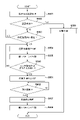
- FIG. 5 is a flowchart showing the procedure of warning processing executed by the control unit 101 of the own vehicle 100 according to the approaching state of the suspicious person according to this embodiment.
- the processing described below is realized, for example, by the CPU of the control unit 101 reading a program held in the ROM or the storage unit 102 into the RAM and executing the program.
- the number following S indicates the step number of each process.
- the approaching state of a suspicious person indicates a state of danger to the own vehicle 100 by a suspicious person.
- the control unit 101 of the own vehicle 100 executes authentication processing of an approaching person approaching the own vehicle 100, as described using FIG. Specifically, the control unit 101 transmits a signal for establishing short-range wireless communication using the key authentication communication device 136 within a predetermined distance range. Authentication information is obtained from the authentication key 220 and authentication processing is executed.
- the control unit 101 determines whether or not the authentication process with the authentication key 220 has succeeded. If the authentication process is successful, the process proceeds to S509, the control unit 101 proceeds to start control of the own vehicle 100, and ends this flowchart. On the other hand, if the authentication process has not succeeded, the control unit 101 identifies the approaching person as a suspicious person and advances the process to S503.
- the case where the authentication process is not successful means the case where the close person does not have the authentication key in the first place and the short-range wireless communication is not established, or the near-field wireless communication is established but the subsequent authentication process is performed. This includes the case where the owner of the own vehicle 100 cannot be determined to be the authorized owner.
- the control unit 101 determines whether or not an approaching person whose authentication processing has not succeeded has approached within a predetermined distance from the own vehicle 100, based on the output of the radar unit 16B. More specifically, the control unit 101 determines whether an approaching person identified as a suspicious person has approached within 3 m from the own vehicle 100 based on the output result of the radar 111, for example. If it approaches, the process proceeds to S504. On the other hand, if it is not approaching, the determination of S503 is repeated. If the person does not approach within the predetermined distance after the predetermined time has passed, or if the person moves away from the range of R2, it is determined that there is no possibility of identifying the suspicious person, and the repeated determination of S503 ends. You may
- the control unit 101 determines that the vehicle 100 may be in danger from a suspicious person.
- the possibility of danger indicates that there is an increased possibility that self-vehicle 100 will be stolen or mischievous by a suspicious person.
- the control unit 101 issues an alarm according to the first pattern. More specifically, the control unit 101 turns on the warning light using at least one of the lighting bodies such as the headlight 11, the taillight 117, and the blinker 115. FIG.
- the control unit 101 determines whether or not at least one of detection by the in-vehicle sensor 106 and input to the operator 105 has occurred. If it has not occurred, the determination of S506 is repeated periodically. Note that when a predetermined time has passed or when the approaching person has left the range of R1 or R2, it may be determined that there is no longer a possibility that the own vehicle 100 will be subjected to a criminal act, and the determination process may be terminated. . On the other hand, if either occurs, the process proceeds to S507, and the control unit 101 determines that the host vehicle 100 is under criminal activity, that is, is in danger.
- the control unit 101 issues an alarm with a second pattern different from the first pattern, and terminates the process. More specifically, the control unit 101 causes the horn 118 or the like to generate a warning sound, for example, in addition to or in place of the warning by the lamp body in the first pattern.
- the behavior of the suspicious person is monitored by switching the warning pattern using sound or light according to the approach state of the approaching person identified as the suspicious person to the own vehicle 100 . It is possible to raise awareness of the fact that It is desirable that the warning be continued until it is determined that there is no danger of a criminal act or a predetermined input is made.
- first pattern and second pattern do not necessarily correspond to the "first pattern” and “second pattern” described in the claims. . In this specification, the same applies to other terms, but “first”, “second”, and “third” merely indicate that they are different from each other.
- FIG. 6 is a flow chart showing a modification of the warning process of FIG.
- the processing described below is realized, for example, by the CPU of the control unit 101 reading a program held in the ROM or the storage unit 102 into the RAM and executing the program.
- the number following S indicates the step number of each process. Further, the same step numbers are assigned to the same processes as in FIG. 5, and the description thereof is omitted.
- the process proceeds to S601, the control unit 101 determines that it is a risk preparation time, and starts counting the number of occurrences.
- the danger preparation time indicates a state in which the possibility of danger to the own vehicle 100 is higher than the danger possibility time.
- the control unit 101 determines whether or not the number of occurrences of at least one of the detection by the in-vehicle sensor 106 and the input to the operator 105 has reached a predetermined number. If the predetermined number of times has been reached, the process proceeds to S507; otherwise, the determination of S602 is periodically repeated.
- control unit 101 determines that the host vehicle 100 is in danger, and thereafter executes the same processing as the processing in FIG.
- the warning was not issued when it was determined that it was a danger preparation time, but the warning may be issued at this timing as well.
- a warning sound may be generated continuously while blinking the body.
- FIG. 7 shows a diagram for explaining the relationship between the host vehicle 100 and the other vehicle 200 according to this embodiment.
- Circles R1 and R2 indicate a range of a predetermined radius from the vehicle 100.
- R1 is set between 5m and 20m, and R2 is set within 5m.
- a person 400 c indicates a suspicious person who has approached the own vehicle 100 .
- 200a to 200c denote other vehicles having imaging units such as cameras.
- own vehicle 100 transmits a signal informing the danger of own vehicle 100 within a predetermined distance according to the approaching state of a suspicious person to own vehicle 100 .
- the signal is transmitted, for example, within a range of R1, for example within a radius of 5 m to 20 m. Therefore, the signal transmitted from own vehicle 100 is received by each of other vehicles 200a, 200b, and 200c located within the range of R1.
- other vehicles located beyond the range R1 from own vehicle 100 cannot receive the signal from own vehicle 100.
- Own vehicle 100 transmits a signal in response to at least one of the approaching state of a suspicious person to own vehicle 100, that is, the danger potential state, danger preparatory state, and danger state.
- the own vehicle 100 transmits a signal indicating the danger possibility of the own vehicle 100 in the dangerous state, and a signal indicating that the own vehicle 100 is in danger (corresponding to the first signal) in the dangerous state.
- the own vehicle 100 transmits a signal (corresponding to a second signal) indicating that the own vehicle 100 is in a danger preparation state in the danger preparation state, and transmits a signal indicating that the own vehicle 100 is in the danger preparation state.
- a signal may be sent to indicate that there is.
- the other vehicles 200a to 200c control activation of their own imaging units according to the received signal. For example, when the other vehicles 200a to 200c receive the signal indicating the possibility of danger or the signal indicating the time of risk preparation, they activate the imaging unit to prepare for photographing, and when they receive the signal indicating the time of danger, You may make it start the imaging
- FIG. This allows for more accurate crime scene evidence to be recorded.
- the other vehicles 200a to 200c grasp the distance from the own vehicle 100 according to the signal strength of the received signal, and, for example, only when they determine that they are located within the range R2 from the own vehicle 100, shoot. you can go As a result, only other vehicles located relatively close to the host vehicle 100 can take pictures, and useless pictures can be reduced.
- the own vehicle 100 may change the transmission range according to the signal to be transmitted.
- the vehicle 100 may transmit signals within R1 during potential danger conditions and within R2 during danger conditions.
- FIG. 8 is a flow chart showing the procedure of warning processing executed by the control unit 101 of the own vehicle 100 according to the approaching state of the suspicious person according to this embodiment.
- the processing described below is realized, for example, by the CPU of the control unit 101 reading a program held in the ROM or the storage unit 102 into the RAM and executing the program.
- the number following S indicates the step number of each process. 5 and 6 are assigned the same step numbers, and descriptions thereof are omitted.
- S504 when an approaching person who has not been successfully authenticated approaches within a predetermined distance L1 from the own vehicle 100, the process proceeds to S801, and the control unit 101 determines that there is a possibility of danger and indicates the possibility of danger.
- a signal is sent, for example, within R1 to start counting the number of occurrences.
- the control unit 101 determines whether or not the number of occurrences of at least one of the detection by the in-vehicle sensor 106 and the input to the operator 105 has reached a predetermined number. If the predetermined number of times has been reached, the process proceeds to S802; otherwise, the determination of S602 is periodically repeated.
- control unit 101 determines that the host vehicle 100 is in danger, transmits a signal indicating the danger within the range of R1 or R2, and then executes the same processing as the processing in FIG.
- FIG. 9 is a flow chart showing a processing procedure of photographing processing of the other vehicle 200 according to this embodiment.
- the processing described below is realized, for example, by the CPU of the control unit 201 reading a program held in the ROM or the storage unit 202 into the RAM and executing the program.
- the number following S indicates the step number of each process.
- FIG. 8 the case where own vehicle 100 transmits a danger preliminary signal and a danger signal will be described. The same processing is performed when a danger possibility signal is received instead of the danger preliminary signal.
- control unit 201 receives a danger preliminary signal (or danger possibility signal) from the own vehicle 100 via the short-range wireless device 206. Subsequently, in S902, the control unit 201 activates at least one of the camera 208 of the imaging unit 204 and the drive recorder 209, and executes preparation processing for photographing.
- a danger preliminary signal or danger possibility signal
- the control unit 201 receives a danger signal from the own vehicle 100 via the short-range wireless device 206 . Subsequently, in S904, the control unit 201 starts shooting with the imaging unit 204 activated in S902. These imaging operations may be performed continuously for a predetermined period of time and periodically, or, for example, in the case of receiving a signal periodically, if the signal is not received for a predetermined period of time, the imaging may be terminated. The details of the determination of whether or not to end shooting will be described later.
- the control unit 201 When the shooting ends, the control unit 201 records the captured image data in the storage unit 202 in S905. Alternatively, it may be stored in a memory card (not shown) or the like. As a result, the memory card can be submitted to an investigative agency that investigates crimes, thereby improving the portability of data and effectively utilizing the storage area. Also, the control unit 201 may transmit the imaging data to the external device 211 via the data transmission unit 207 . Accordingly, the imaged data is held in the storage unit 212 of the external device 211, and the imaged data of each vehicle can be collectively managed.
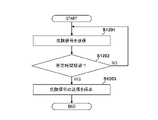
- FIG. 10 is a flow chart showing a modification of the processing procedure when the own vehicle 100 transmits the danger signal. This flowchart shows the processing executed when the GPS 134 is powered off.
- the processing described below is realized, for example, by the CPU of the control unit 101 reading a program held in the ROM or the storage unit 102 into the RAM and executing the program.
- the number following S indicates the step number of each process.
- the control unit 101 determines whether or not the power to the GPS 134 was cut off according to a normal procedure.
- the normal procedure refers to a procedure in which the power supply is cut off by disabling the function of the GPS 134 according to a predetermined procedure on an operation panel (not shown) or the like.
- the illegal procedure is, for example, when a suspicious person steals the own vehicle 100, the power supply is cut off by physically disconnecting the power cable of the GPS 134 because the position of the vehicle after the theft cannot be grasped. indicates the case. Therefore, when the input of the position information from the GPS 134 stops without performing the regular procedure, the control unit 101 determines that the power supply to the GPS 134 has been cut off by a procedure different from the regular procedure. In that case, the process advances to S1002, and if it is determined that the normal procedure has been performed, this flowchart ends.
- the control unit 101 determines that the vehicle 100 is in danger by a suspicious person, transmits a signal indicating danger within the range of R1 or R2, and terminates this flowchart.
- the danger signal may be transmitted regardless of whether the suspicious person is identified, or the danger signal may be transmitted only when the suspicious person approaching the own vehicle 100 is identified.
- the other vehicle 200 that has received the emergency signal executes the processes of S903 to S905 described with reference to FIG.
- a suspicious person may disconnect the short-range wireless device 135 of the own vehicle 100 .
- the other vehicle 200 starts photographing when it stops receiving danger signals such as danger potential signals, danger preliminary signals, and danger signals periodically transmitted from the own vehicle 100. You may make it Thereby, even when the communication device is disconnected, it is possible to start shooting at an appropriate timing.
- FIG. 11 is a flow chart showing a modified example of the processing procedure of the photographing processing of the other vehicle 200. As shown in FIG. The processing described below is realized, for example, by the CPU of the control unit 201 reading a program held in the ROM or the storage unit 202 into the RAM and executing the program. The number following S indicates the step number of each process. Further, the same step numbers are attached to the same processing as in FIG. 9, and the description thereof is omitted.
- the control unit 201 receives the danger signal from the own vehicle 100. Subsequently, in S1102, the control unit 201 determines whether or not the distance to the own vehicle 100 is within the range of R2, for example, within 5 m. For example, the control unit 201 may determine the distance to the own vehicle 100 according to the signal strength received in S1101, or may measure the distance to the own vehicle 100 using a radar unit (not shown). If it is within the range of R2, proceed to S904; otherwise, proceed to S1103d. After proceeding to S904, the control unit 201 starts shooting and executes the same processing as in FIG.
- control unit 201 determines whether or not the distance to the own vehicle 100 is within the range of R1, for example, within 20m.
- the distance to own vehicle 100 is determined in the same manner as in S1102. If it is within the range of R1, the process proceeds to S902; otherwise, the flow chart ends.
- the control unit 201 activates the imaging unit to prepare for imaging, and returns the process to S1101. After that, when the danger signal is periodically received, the imaging unit is placed in a standby state until it is positioned within the range of R2. As described above, in the modification, after the other vehicle 200 receives a danger signal from the own vehicle 100 indicating danger, the distance to the own vehicle 100 is measured, and the imaging unit is activated according to the measurement result to set the vehicle in the standby state. or to start shooting.
- FIG. 12 explains the processing related to the end of the photographing processing of the host vehicle 100 and the other vehicle 200.
- FIG. FIG. 12A shows the processing after the host vehicle 100 has transmitted the danger signal
- FIG. 12B shows the processing after the other vehicle 200 receives the danger signal.
- the processing described below is realized by, for example, CPUs of the control units 101 and 201 reading programs held in the ROM and the storage units 102 and 202 into the RAM and executing the programs.
- the number following S indicates the step number of each process.
- the control unit 101 transmits a danger signal.
- the danger signal here corresponds to the signal transmitted in S801 or S802.
- the vehicle 100 may transmit a constant signal without switching the signal according to the approaching state of the suspicious person.
- the control unit 101 starts timing a predetermined time.
- the control unit 101 determines whether or not the time that started measuring in S1201 has passed a predetermined time, for example, one minute. If the predetermined time has elapsed, the process proceeds to S1203, and if not, the process returns to S1201 to continue transmitting the danger signal. In S1203, the control unit 101 stops transmitting the danger signal and ends this flowchart.
- a predetermined time for example, one minute.
- the control unit 201 receives a danger signal from the own vehicle 100, activates the imaging unit, and puts it in a standby state. Also, the control unit 201 starts timing a predetermined time. Subsequently, in S1212, the control unit 201 determines whether or not the clocked time has passed a predetermined time, for example, 1 minute. After the predetermined time has elapsed, the process advances to step S1213, and the control unit 201 starts photographing by the imaging unit.
- the own vehicle 100 stops transmitting the danger signal after a predetermined period of time has passed, and the other vehicle 200 receives the danger signal and starts shooting after a predetermined period of time has passed. Note that it is desirable that the other vehicle 200 starts shooting when it continues to receive the danger signal even after the predetermined time has passed. As a result, it is possible to reduce erroneous operations such as when the transmission of the danger signal is stopped when the danger is avoided.
- FIG. 13 is a flowchart showing another processing procedure of photographing processing by the other vehicle 200.
- the processing described below is realized, for example, by the CPU of the control unit 201 reading a program held in the ROM or the storage unit 202 into the RAM and executing the program.
- the number following S indicates the step number of each process. Further, the same step numbers are attached to the same processing as in FIG. 9, and the description thereof is omitted.
- the control unit 201 uses the signal strength of the danger signal received from the own vehicle 100 or a radar unit (not shown) to determine whether the distance from the own vehicle 100 is within a predetermined distance, for example, the range of R2. It is judged whether it is within 5m. If it is within the predetermined distance, the determination in S1301 is repeated. If it is not within the predetermined distance, for example, if it is determined that the other vehicle 200 is not within the range R2 from the own vehicle 100, the process proceeds to S1302.
- a predetermined distance for example, the range of R2.
- control unit 201 stops shooting. Subsequently, in S1303, the control unit 201 acquires position information using the GPS 205 and adds it to the imaging data captured after S1301. After that, in S905, the control unit 201 stores the imaging data in the storage unit 202, transmits it to the external device 211 via the data transmission unit 207, and ends this flowchart.
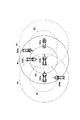
- FIG. 14 is a diagram showing the effect of the flowchart in FIG. 100a to 100c indicate own vehicles.
- the stolen own vehicle 100 is shown moving in the order of 100a, 100b, and 100c.
- 200a to 200c indicate other vehicles.
- Circles R1 and R2 indicate a range of a predetermined radius from the vehicle 100a-100c. For example, R1 is set between 5m and 20m, and R2 is set within 5m.
- Dotted lines R1 and R2 indicate radii from the host vehicle 100a.
- Solid lines R1 and R2 indicate radii from the host vehicle 100b.
- R1 and R2 indicated by dashed lines indicate radii from the host vehicle 100c.
- the other vehicle 200a When the control described above is performed using FIG. 13, the other vehicle 200a is located within the range indicated by the dotted line R2 at the position of the own vehicle 100a, so that it is photographed.
- the other vehicle 200a when the subject vehicle 100b or 100c moves to the position, the other vehicle 200a is not positioned within the range of R2 indicated by the solid line or the one-dot chain line, so the photographing ends.
- the other vehicle 200b shoots at the position of its own vehicle 100b, but finishes shooting at the position of its own vehicle 100c.
- the other vehicle 200c takes the image at the position of the own vehicle 100c, the image taking ends when the own vehicle 100c moves further and the other vehicle 200c is out of the range of R2.
- each of the other vehicles 200a to 200c obtains the positional information, adds it to the photographed data, stores it, and transmits it to the external device 211.
- each of the other vehicles 200a to 200c receives the danger signal, it determines the distance from the own vehicle 100 and determines the end of shooting. For example, when the imaging unit of the other vehicle 200 is provided in front of the vehicle, it is possible to photograph a predetermined range in the forward direction, but it is not possible to photograph positions beyond that range. In other words, since the other vehicle 200 has a limited imaging range, it is desirable to end the imaging by determining that the own vehicle 100 cannot be imaged when the distance from the own vehicle 100 is to some extent. It is desirable that this distance can be changed by setting based on the performance of the camera. If the shooting direction of the camera can be changed, it is possible to set a wider shooting range. By determining the end of photographing by the other vehicle 200 in this way, the control of the own vehicle 100 can be simplified and unnecessary photographing can be avoided.
- FIG. 15 explains processing related to the end of photographing processing of own vehicle 100 and other vehicle 200 .
- FIG. 15A shows processing when own vehicle 100 is determined to be in a dangerous state
- FIG. 15B shows processing after other vehicle 200 starts photographing.
- the processing described below is realized by, for example, CPUs of the control units 101 and 201 reading programs held in the ROM and the storage units 102 and 202 into the RAM and executing the programs.
- the number following S indicates the step number of each process.
- the control unit 101 determines that the host vehicle 100 is in danger by a suspicious person and transmits an emergency signal. Note that the determination of these dangerous states is the same as the control described with reference to FIG. 8, so description thereof will be omitted.
- the control unit 101 issues an alarm using the second pattern as described above.
- the control unit 101 determines whether the dangerous state of the own vehicle 100 is a dangerous state, a danger preparatory state, or a possible danger state. Repeat periodically. On the other hand, if it is determined that none of the dangerous states exist, the control unit 101 advances to S1506 and determines whether or not a predetermined time has elapsed. The predetermined time indicates the elapsed time since it was last determined to be one of the dangerous states. Five minutes, for example, is set as the predetermined time. If the predetermined time has not passed, the process returns to S1503, and if it is determined that the predetermined time has passed, the process proceeds to S1507. ) and terminate the process. In addition, since there is a possibility that the other vehicle 200 cannot receive the signal with one transmission, it is desirable to continuously transmit the danger evacuation signal for a predetermined period of time.
- the control unit 201 determines whether or not a retraction signal has been received after the start of imaging. Upon receiving the evacuation signal, the control unit 201 advances to S ⁇ b>1512 and acquires position information using the GPS 205 . Subsequently, in S1513, the control unit 201 attaches the acquired position information to the imaging data, transmits the imaging data to the external device 211, and ends the process. In this way, it may be determined whether or not the host vehicle 100 has escaped from a dangerous state, and if the host vehicle 100 has escaped, a signal indicating that fact may be transmitted to end the photographing of the other vehicle 200 .
- At least one in-vehicle sensor (106) that detects the state of the vehicle, at least one distance sensor (103) that measures the distance between the vehicle and other objects, and at least one sensor that operates the vehicle.
- a vehicle (100) comprising two operators (105), a wireless communication means (135) for transmitting a signal by wireless communication to one or more other vehicles; determination means (S502, S503, 101) for determining whether or not authentication by communication with the vehicle key is successful when the output of the at least one distance sensor indicates a person approaching the vehicle;
- the wireless communication means detects one or more other vehicles.
- a control means (S802, 101) for causing the other vehicle that receives the first signal to perform the first action.
- the first action is an operation of photographing at least one of a still image and a moving image by an imaging means provided in the other vehicle (S904).
- lamp bodies (11, 115, 117) that emit light; a sound generator (118) that emits sound;
- the control means is When at least one of the detection by the at least one in-vehicle sensor and the input to the at least one operation element occurs when the determining means determines that the authentication has failed, the lighting body and the sound generating device further (S508).
- the control means is When the determining means determines that the authentication has failed and the at least one distance sensor detects that the approaching person has approached the vehicle to a predetermined distance, the wireless communication means performs one or more The other vehicle is caused to transmit a second signal, and the other vehicle that has received the second signal is caused to perform a second action as a preparatory operation for the first action (S801).
- the signal can be switched and transmitted according to the dangerous state in more detail, and other vehicles that have received the signal can shoot at appropriate timing while suppressing battery consumption. . 5.
- the wireless communication means periodically transmits at least one of the first signal and the second signal (S801, S802, S1203).
- the second action is the activation operation of the imaging means provided in the other vehicle (S902).
- the signal can be switched and transmitted according to the dangerous state in more detail, and other vehicles that have received the signal can shoot at appropriate timing while suppressing battery consumption. .
- the control means is When the determining means determines that the authentication has failed and the at least one distance sensor detects that the approaching person has approached the vehicle within a predetermined distance, the light body and the sound generating device and (S505).
- the alarm pattern can be switched in more detail according to the dangerous state of the vehicle by the suspicious person, giving the suspicious person psychological surprise and enhancing the ability to deter crime. .
- the control means is before a predetermined time elapses after at least one of the detection by the at least one in-vehicle sensor and the input to the at least one operator occurs when the determination means determines that the authentication has failed
- the wireless communication means transmits the first signal to one or more other vehicles.
- the control means is When the determining means determines that the authentication has failed and at least one of the detection by the at least one in-vehicle sensor and the input to the at least one operator occurs, the lamp and An alarm is issued in a third pattern using at least one of the sound generating device, and if the number of occurrences reaches a predetermined number of times before the predetermined time elapses from the first occurrence, the alarm is issued in the first pattern.
- the alarm pattern can be switched in more detail according to the dangerous state of the vehicle by the suspicious person, giving the suspicious person psychological surprise and enhancing the ability to deter crime. .
- the first signal is transmitted to one or more other vehicles by the wireless communication means (S1001, S1002).
- the one or more other vehicles when the one or more other vehicles receive the first signal, the one or more other vehicles are located within a first distance range from the one or more other vehicles. is started (S1102, S904).
- other vehicles that have received the signal can start shooting at an appropriate timing, reduce battery consumption, and effectively utilize memory resources for recording image data.
- the imaging means provided in the one or more other vehicles starts photographing.
- the imaging means Shooting ends (S1301, S1302).
- control means controls the detection by the at least one vehicle-mounted sensor and the detection by the at least one vehicle-mounted sensor and the if no input is made to the at least one operator, causing the wireless communication means to transmit a third signal to one or more other vehicles (S1507); In the one or more other vehicles, when the third signal is received after the photographing by the photographing means is started, the photographing by the photographing means is finished (S1511).
- the captured image data is transferred to the external device via the network (S905).
- the imaging data can be reliably secured, and the crime after theft can be suitably analyzed.
- the position information at the time of photographing by the position information measuring means provided in the one or more other vehicles is acquired and transmitted. It is added to the imaging data (S1303, S1512).
- the camera can be activated and shooting can be started at appropriate timing, and crime prevention can be enhanced.
- the position information measuring means (205) for measuring the position of the vehicle is further provided,
- the transfer means adds position information at the time of photographing to the imaging data and transfers the imaging data (S1303, S1512).
- At least one in-vehicle sensor (106) that detects the state of the vehicle, at least one distance sensor (103) that measures the distance between the vehicle and other objects, and at least one operation that operates the vehicle.
- the first vehicle is a wireless communication means (135) for transmitting a signal by wireless communication to another vehicle; determining means (S502, S503, 101) for determining whether or not authentication by communication with the vehicle key is successful when the output of the at least one distance sensor indicates a person approaching the vehicle; When it is determined that the authentication has failed by the determination means, When at least one of the detection by the at least one in-vehicle sensor and the input to the at least one operator occurs when the determination means determines that the authentication has failed, the wireless communication means detects one or more other vehicles.
- control means for transmitting a first signal to and causing another vehicle that receives the first signal to perform a first action
- the second vehicle is an imaging means (204) for starting imaging upon receiving the first signal from the first vehicle; and transfer means (207) for transferring image data captured by the imaging means to an external device via a network.
Landscapes
- Engineering & Computer Science (AREA)
- Operations Research (AREA)
- Business, Economics & Management (AREA)
- Accounting & Taxation (AREA)
- Development Economics (AREA)
- Economics (AREA)
- General Business, Economics & Management (AREA)
- Computing Systems (AREA)
- Multimedia (AREA)
- Signal Processing (AREA)
- Computer Networks & Wireless Communication (AREA)
- Mechanical Engineering (AREA)
- Closed-Circuit Television Systems (AREA)
- Selective Calling Equipment (AREA)
- Traffic Control Systems (AREA)
Priority Applications (2)
| Application Number | Priority Date | Filing Date | Title |
|---|---|---|---|
| JP2023504978A JP7439341B2 (ja) | 2021-03-10 | 2021-03-10 | 車両及び防犯システム |
| PCT/JP2021/009589 WO2022190276A1 (ja) | 2021-03-10 | 2021-03-10 | 車両及び防犯システム |
Applications Claiming Priority (1)
| Application Number | Priority Date | Filing Date | Title |
|---|---|---|---|
| PCT/JP2021/009589 WO2022190276A1 (ja) | 2021-03-10 | 2021-03-10 | 車両及び防犯システム |
Publications (1)
| Publication Number | Publication Date |
|---|---|
| WO2022190276A1 true WO2022190276A1 (ja) | 2022-09-15 |
Family
ID=83227638
Family Applications (1)
| Application Number | Title | Priority Date | Filing Date |
|---|---|---|---|
| PCT/JP2021/009589 Ceased WO2022190276A1 (ja) | 2021-03-10 | 2021-03-10 | 車両及び防犯システム |
Country Status (2)
| Country | Link |
|---|---|
| JP (1) | JP7439341B2 (https=) |
| WO (1) | WO2022190276A1 (https=) |
Cited By (1)
| Publication number | Priority date | Publication date | Assignee | Title |
|---|---|---|---|---|
| CN116080555A (zh) * | 2023-01-06 | 2023-05-09 | 中国第一汽车股份有限公司 | 车辆异动检测方法、装置及车辆 |
Citations (10)
| Publication number | Priority date | Publication date | Assignee | Title |
|---|---|---|---|---|
| JP2001247013A (ja) * | 1999-12-27 | 2001-09-11 | Fuji Denki Kogyo Kk | 盗難警報装置 |
| JP4375155B2 (ja) * | 2004-07-28 | 2009-12-02 | マツダ株式会社 | 自動車の盗難防止システム |
| JP2011240880A (ja) * | 2010-05-20 | 2011-12-01 | Autonetworks Technologies Ltd | 車両用盗難防止装置 |
| JP2011251563A (ja) * | 2010-05-31 | 2011-12-15 | Toyota Motor Corp | 防犯装置及び防犯システム |
| JP2017156897A (ja) * | 2016-02-29 | 2017-09-07 | 本田技研工業株式会社 | 車両、画像表示装置、車両の制御方法、および画像表示方法 |
| JP2018052238A (ja) * | 2016-09-28 | 2018-04-05 | 本田技研工業株式会社 | カメラ映像表示装置 |
| CN107963055A (zh) * | 2017-11-23 | 2018-04-27 | 李党 | 车辆防盗系统 |
| JP2019091230A (ja) * | 2017-11-14 | 2019-06-13 | グローリー株式会社 | 車両監視システム、監視装置および情報共有方法 |
| CN110103878A (zh) * | 2019-05-22 | 2019-08-09 | 北京百度网讯科技有限公司 | 用于控制无人车的方法和装置 |
| JP2020132073A (ja) * | 2019-02-25 | 2020-08-31 | 株式会社デンソー | 車両用防犯システム及び車両用防犯装置 |
Family Cites Families (2)
| Publication number | Priority date | Publication date | Assignee | Title |
|---|---|---|---|---|
| JPH09327012A (ja) * | 1996-06-04 | 1997-12-16 | Sumitomo Electric Ind Ltd | 画像監視装置 |
| KR101413924B1 (ko) * | 2012-12-05 | 2014-07-01 | 한국남부발전 주식회사 | 건설현장에서 위험 경보를 신속히 전송하기 위한 시스템 |
-
2021
- 2021-03-10 WO PCT/JP2021/009589 patent/WO2022190276A1/ja not_active Ceased
- 2021-03-10 JP JP2023504978A patent/JP7439341B2/ja active Active
Patent Citations (10)
| Publication number | Priority date | Publication date | Assignee | Title |
|---|---|---|---|---|
| JP2001247013A (ja) * | 1999-12-27 | 2001-09-11 | Fuji Denki Kogyo Kk | 盗難警報装置 |
| JP4375155B2 (ja) * | 2004-07-28 | 2009-12-02 | マツダ株式会社 | 自動車の盗難防止システム |
| JP2011240880A (ja) * | 2010-05-20 | 2011-12-01 | Autonetworks Technologies Ltd | 車両用盗難防止装置 |
| JP2011251563A (ja) * | 2010-05-31 | 2011-12-15 | Toyota Motor Corp | 防犯装置及び防犯システム |
| JP2017156897A (ja) * | 2016-02-29 | 2017-09-07 | 本田技研工業株式会社 | 車両、画像表示装置、車両の制御方法、および画像表示方法 |
| JP2018052238A (ja) * | 2016-09-28 | 2018-04-05 | 本田技研工業株式会社 | カメラ映像表示装置 |
| JP2019091230A (ja) * | 2017-11-14 | 2019-06-13 | グローリー株式会社 | 車両監視システム、監視装置および情報共有方法 |
| CN107963055A (zh) * | 2017-11-23 | 2018-04-27 | 李党 | 车辆防盗系统 |
| JP2020132073A (ja) * | 2019-02-25 | 2020-08-31 | 株式会社デンソー | 車両用防犯システム及び車両用防犯装置 |
| CN110103878A (zh) * | 2019-05-22 | 2019-08-09 | 北京百度网讯科技有限公司 | 用于控制无人车的方法和装置 |
Cited By (2)
| Publication number | Priority date | Publication date | Assignee | Title |
|---|---|---|---|---|
| CN116080555A (zh) * | 2023-01-06 | 2023-05-09 | 中国第一汽车股份有限公司 | 车辆异动检测方法、装置及车辆 |
| CN116080555B (zh) * | 2023-01-06 | 2025-09-09 | 中国第一汽车股份有限公司 | 车辆异动检测方法、装置及车辆 |
Also Published As
| Publication number | Publication date |
|---|---|
| JPWO2022190276A1 (https=) | 2022-09-15 |
| JP7439341B2 (ja) | 2024-02-27 |
Similar Documents
| Publication | Publication Date | Title |
|---|---|---|
| US12459468B2 (en) | Vehicle control device and vehicle control method | |
| JP6996773B2 (ja) | スクータ | |
| CN111114514B (zh) | 邻近的行人碰撞减轻 | |
| JP5022272B2 (ja) | 走行支援装置 | |
| JP5978483B2 (ja) | スマートパーキングアシストシステム | |
| WO2018058273A1 (zh) | 一种防盗方法及系统 | |
| JP7439341B2 (ja) | 車両及び防犯システム | |
| CN113443051B (zh) | 跨骑型车辆以及控制装置 | |
| CN208585172U (zh) | 一种具有预警功能的流媒体后视镜系统 | |
| CN101123013B (zh) | 车辆控制装置及设有该控制装置的车辆 | |
| JP4066892B2 (ja) | 車両用警報装置 | |
| JP6403378B2 (ja) | 安全運転支援装置および安全運転支援方法 | |
| JP7664066B2 (ja) | プログラム、及びシステム | |
| KR20130101821A (ko) | 차량 속도에 따라 충격 감지 민감도를 가변하는 블랙박스 및 그 제어방법 | |
| JP7000851B2 (ja) | 運転支援装置 | |
| JP3176875U (ja) | カーセキュリティーシステムと連動してドライブレコーダーを動作させるためのタイマーを内蔵したアダプター | |
| CN201286139Y (zh) | 具防盗及监视功能的行车记录装置 | |
| JP2018045357A (ja) | 運転支援装置 | |
| JP7725275B2 (ja) | システム、車両、携帯端末、及びそれらの方法 | |
| JP7620465B2 (ja) | プログラム、鞍乗型車両、及びシステム | |
| TWI867696B (zh) | 行車警示系統及方法 | |
| WO2025017914A1 (ja) | 情報処理装置、情報処理方法、及びプログラム | |
| JP2007085745A (ja) | 物体監視装置 | |
| WO2022130742A1 (ja) | 表示制御装置、表示制御システム及び表示制御方法 | |
| WO2022196307A1 (ja) | 乗物の乗員識別装置 |
Legal Events
| Date | Code | Title | Description |
|---|---|---|---|
| 121 | Ep: the epo has been informed by wipo that ep was designated in this application |
Ref document number: 21929437 Country of ref document: EP Kind code of ref document: A1 |
|
| WWE | Wipo information: entry into national phase |
Ref document number: 2023504978 Country of ref document: JP |
|
| WWE | Wipo information: entry into national phase |
Ref document number: 202347058395 Country of ref document: IN |
|
| NENP | Non-entry into the national phase |
Ref country code: DE |
|
| 122 | Ep: pct application non-entry in european phase |
Ref document number: 21929437 Country of ref document: EP Kind code of ref document: A1 |
|
| WWG | Wipo information: grant in national office |
Ref document number: 202347058395 Country of ref document: IN |