WO2022190276A1 - Vehicle and security system - Google Patents
Vehicle and security system Download PDFInfo
- Publication number
- WO2022190276A1 WO2022190276A1 PCT/JP2021/009589 JP2021009589W WO2022190276A1 WO 2022190276 A1 WO2022190276 A1 WO 2022190276A1 JP 2021009589 W JP2021009589 W JP 2021009589W WO 2022190276 A1 WO2022190276 A1 WO 2022190276A1
- Authority
- WO
- WIPO (PCT)
- Prior art keywords
- vehicle
- signal
- vehicles
- imaging
- wireless communication
- Prior art date
Links
- 238000004891 communication Methods 0.000 claims abstract description 72
- 238000001514 detection method Methods 0.000 claims abstract description 32
- 230000009471 action Effects 0.000 claims abstract description 14
- 238000003384 imaging method Methods 0.000 claims description 82
- 238000000034 method Methods 0.000 claims description 78
- 238000012546 transfer Methods 0.000 claims description 9
- 230000004913 activation Effects 0.000 claims description 4
- 238000012545 processing Methods 0.000 description 68
- 230000008569 process Effects 0.000 description 45
- 230000005540 biological transmission Effects 0.000 description 12
- 230000004048 modification Effects 0.000 description 12
- 238000012986 modification Methods 0.000 description 12
- 230000002265 prevention Effects 0.000 description 12
- 238000013459 approach Methods 0.000 description 11
- 238000005516 engineering process Methods 0.000 description 7
- 230000007246 mechanism Effects 0.000 description 7
- 238000010586 diagram Methods 0.000 description 6
- 230000000694 effects Effects 0.000 description 6
- 238000012806 monitoring device Methods 0.000 description 4
- 238000013500 data storage Methods 0.000 description 3
- 230000002708 enhancing effect Effects 0.000 description 2
- 239000002828 fuel tank Substances 0.000 description 2
- 230000006870 function Effects 0.000 description 2
- 238000011835 investigation Methods 0.000 description 2
- 239000011347 resin Substances 0.000 description 2
- 229920005989 resin Polymers 0.000 description 2
- 239000000725 suspension Substances 0.000 description 2
- 208000019901 Anxiety disease Diseases 0.000 description 1
- 239000006096 absorbing agent Substances 0.000 description 1
- 230000001133 acceleration Effects 0.000 description 1
- 230000003213 activating effect Effects 0.000 description 1
- 230000036506 anxiety Effects 0.000 description 1
- 230000006399 behavior Effects 0.000 description 1
- 230000004397 blinking Effects 0.000 description 1
- 230000008859 change Effects 0.000 description 1
- 230000006866 deterioration Effects 0.000 description 1
- 239000000463 material Substances 0.000 description 1
- 238000005259 measurement Methods 0.000 description 1
- 230000003287 optical effect Effects 0.000 description 1
- 230000004044 response Effects 0.000 description 1
- 230000035939 shock Effects 0.000 description 1
- 238000004904 shortening Methods 0.000 description 1
- 230000008054 signal transmission Effects 0.000 description 1
- 230000001960 triggered effect Effects 0.000 description 1
Images


Classifications
-
- B—PERFORMING OPERATIONS; TRANSPORTING
- B60—VEHICLES IN GENERAL
- B60R—VEHICLES, VEHICLE FITTINGS, OR VEHICLE PARTS, NOT OTHERWISE PROVIDED FOR
- B60R25/00—Fittings or systems for preventing or indicating unauthorised use or theft of vehicles
- B60R25/20—Means to switch the anti-theft system on or off
- B60R25/24—Means to switch the anti-theft system on or off using electronic identifiers containing a code not memorised by the user
-
- G—PHYSICS
- G16—INFORMATION AND COMMUNICATION TECHNOLOGY [ICT] SPECIALLY ADAPTED FOR SPECIFIC APPLICATION FIELDS
- G16Y—INFORMATION AND COMMUNICATION TECHNOLOGY SPECIALLY ADAPTED FOR THE INTERNET OF THINGS [IoT]
- G16Y10/00—Economic sectors
- G16Y10/40—Transportation
-
- H—ELECTRICITY
- H04—ELECTRIC COMMUNICATION TECHNIQUE
- H04N—PICTORIAL COMMUNICATION, e.g. TELEVISION
- H04N7/00—Television systems
- H04N7/18—Closed-circuit television [CCTV] systems, i.e. systems in which the video signal is not broadcast
-
- H—ELECTRICITY
- H04—ELECTRIC COMMUNICATION TECHNIQUE
- H04Q—SELECTING
- H04Q9/00—Arrangements in telecontrol or telemetry systems for selectively calling a substation from a main station, in which substation desired apparatus is selected for applying a control signal thereto or for obtaining measured values therefrom
Definitions
- the present invention relates to vehicles and security systems.
- Patent Literature 1 proposes a technique for changing the output sound in a vehicle anti-theft or harm prevention device that senses vehicle body vibration and outputs voice for theft or harm prevention. Further, in Patent Document 2, even if it is determined that the user of the vehicle is not an authorized user when the radio signal is received, when it is determined that the transmission is from an authorized user of a nearby vehicle, a suspicious person is detected. proposed a security device that disables Further, Patent Document 3 proposes, in a detection system for detecting a detection target approaching a driving own vehicle, a technique for controlling an acoustic system according to the direction of approach so that the driver can hear from that direction.
- the purpose of the present invention is to provide a new crime prevention mechanism by cooperating with other vehicles to take measures according to the degree of danger to the vehicle by suspicious persons.
- At least one in-vehicle sensor that detects the state of the vehicle, at least one distance sensor that measures the distance between the vehicle and other objects, and at least one operator that operates the vehicle are provided.
- a vehicle wireless communication means for transmitting a signal by wireless communication to one or more other vehicles; determining means for determining whether or not authentication by communication with the vehicle key is successful when the output of the at least one distance sensor indicates a person approaching the vehicle;
- the wireless communication means detects one or more other vehicles. and control means for causing the other vehicle that receives the first signal to perform the first action.
- a new crime prevention mechanism can be provided by cooperating with other vehicles to take measures according to the degree of danger to the vehicle by the suspicious person.
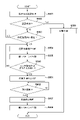
- FIG. 1 is a right side view of a straddle-type vehicle according to an embodiment
- FIG. FIG. 2 is a front view of the straddle-type vehicle of FIG. 1
- 1 is a block diagram showing the control configuration of the security system according to one embodiment
- FIG. 4 is a flow chart showing a processing procedure of warning processing for own vehicle according to the first embodiment
- 6 is a flowchart showing a modification of FIG. 5; The figure which shows the relationship between the own vehicle and other vehicles which concern on one Embodiment.
- FIG. 10 is a flowchart showing a processing procedure of warning processing for own vehicle according to the second embodiment
- FIG. 11 is a flow chart showing a processing procedure of photographing processing of another vehicle according to the second embodiment
- FIG. 4 is a flowchart showing another processing procedure when transmitting a danger signal
- 4 is a flowchart showing another processing procedure of another vehicle when receiving a danger signal
- 4 is a flowchart showing another processing procedure of another vehicle when receiving a danger signal
- 4 is a flowchart showing another processing procedure of another vehicle when receiving a danger signal
- 4 is a flowchart showing another processing procedure of another vehicle when receiving a danger signal
- 4 is a flow chart showing another processing procedure of another vehicle in the photographing process
- 14A and 14B are diagrams for explaining the effect of the processing of FIG. 13
- FIG. FIG. 10 is a flowchart showing another processing procedure of another vehicle when finishing photographing
- FIG. FIG. 10 is a flowchart showing another processing procedure of another vehicle when finishing photographing
- arrows X, Y, and Z indicate directions orthogonal to each other, the X direction being the front-rear direction of the saddle-ride type vehicle, the Y direction being the vehicle width direction (horizontal direction) of the saddle-ride type vehicle, and the Z direction being the vertical direction.
- the left and right sides of the straddle-type vehicle are the left and right sides when viewed in the forward direction.
- the front or rear in the longitudinal direction of the straddle-type vehicle may simply be referred to as the front or rear.
- the inner side or the outer side in the vehicle width direction (horizontal direction) of the straddle-type vehicle may be simply referred to as the inner side or the outer side.
- FIG. 1 is a right side view of a straddle-type vehicle 1 according to an embodiment of the present invention
- FIG. 2 is a front view of the straddle-type vehicle 1. As shown in FIG.
- the straddle-type vehicle 1 is a tourer-type motorcycle suitable for long-distance travel, but the present invention is applicable to various straddle-type vehicles including other types of motorcycles. It can be applied to an electric vehicle using a motor as a drive source as well as a vehicle using a motor as a drive source.
- the straddle-type vehicle 1 may be referred to as the vehicle 1 hereinafter.
- a two-wheel saddle type vehicle will be described as an example of a vehicle, but the present invention is not intended to be limited and can be applied to various vehicles such as a four-wheel drive vehicle.
- the vehicle 1 has a power unit 2 between the front wheels FW and the rear wheels RW.
- the power unit 2 includes a horizontally opposed six-cylinder engine 21 and a transmission 22 .
- the driving force of the transmission 22 is transmitted to the rear wheels RW via a drive shaft (not shown) to rotate the rear wheels RW.
- the power unit 2 is supported by the body frame 3.
- the body frame 3 includes a pair of left and right main frames 31 extending in the X direction.
- a fuel tank 5 and an air cleaner box (not shown) are arranged above the main frame 31 .
- a meter panel MP equipped with an electronic image display device for displaying various information to the rider.
- a head pipe 32 that rotatably supports a steering shaft (not shown) rotated by the handle 8 is provided at the front end of the main frame 31 .
- a pair of left and right pivot plates 33 are provided at the rear end of the main frame 31 .
- a lower end portion of the pivot plate 33 and a front end portion of the main frame 31 are connected by a pair of left and right lower arms (not shown), and the power unit 2 is supported by the main frame 31 and the lower arms.
- a pair of left and right seat rails (not shown) extending rearward are provided at the rear end of the main frame 31.
- the seat rails are a seat 4a on which a rider sits, a seat 4b on which a fellow passenger sits, and a rear trunk. 7b etc. are supported.
- the pivot plate 33 swingably supports the front end of a rear swing arm (not shown) extending in the front-rear direction.
- the rear swing arm is vertically swingable, and supports the rear wheel RW at its rear end.
- An exhaust muffler 6 that muffles exhaust noise from the engine 21 extends in the X direction below the rear wheel RW.
- Left and right saddlebags 7a are provided on the upper side of the rear wheel RW.
- a front suspension mechanism 9 that supports the front wheels FW is configured at the front end of the main frame 31 .
- the front suspension mechanism 9 includes an upper link 91 , a lower link 92 , a fork support 93 , a cushion unit 94 and a pair of left and right front forks 95 .
- the upper link 91 and the lower link 92 are arranged at the front end of the main frame 31 with a vertical gap therebetween. Rear ends of the upper link 91 and the lower link 92 are pivotably connected to support portions 31 a and 31 b provided at the front end of the main frame 31 . Front ends of the upper link 91 and the lower link 92 are pivotably connected to a fork support 93 .
- the upper link 91 and the lower link 92 each extend in the front-rear direction and are arranged substantially in parallel.
- the cushion unit 94 has a structure in which a shock absorber is inserted through a coil spring, and its upper end is supported by the main frame 31 so as to be swingable. A lower end portion of the cushion unit 94 is swingably supported by the lower link 92 .
- the fork support 93 is cylindrical and tilts backward.
- the front end of the upper link 91 is rotatably connected to the upper front portion of the fork support 93 .
- a front end portion of the lower link 92 is rotatably connected to the lower rear portion of the fork support 93 .
- a steering shaft 96 is rotatably supported on the fork support 93 about its axis.
- the steering shaft 96 has a shaft portion (not shown) through which the fork support 93 is inserted.
- a bridge (not shown) is provided at the lower end of the steering shaft 96, and a pair of left and right front forks 95 are supported by this bridge.
- the front wheel FW is rotatably supported by the front fork 95 .
- the upper end of the steering shaft 96 is connected via a link 97 to a steering shaft (not shown) rotated by the handle 8 . Steering of the steering wheel 8 rotates the steering shaft 96 to steer the front wheels FW.
- the vehicle 1 includes a brake device 19F that brakes the front wheels FW and a brake device 19F that brakes the rear wheels RW.
- the brake devices 19F and 19R are configured to be operable by the rider's operation of the brake lever 8a or the brake pedal 8b.
- Brake devices 19F and 19R are, for example, disc brakes. When not distinguishing between the brake devices 19F and 19R, they are collectively referred to as the brake device 19. As shown in FIG.
- a headlight 11 that emits light in front of the vehicle 1 is arranged in the front part of the vehicle 1 .
- the headlight 11 of the present embodiment is a twin-lens type headlight unit that includes a right light irradiation section 11R and a left light irradiation section 11L symmetrically.
- a single-lens type headlight unit, a three-lens type headlight unit, or a left-right asymmetric two-lens type headlight unit can also be employed.
- the front part of the vehicle 1 is covered with a front cowl 12, and the front side part of the vehicle 1 is covered with a pair of left and right side cowls 14.
- a screen 13 is arranged above the front cowl 12 .
- the screen 13 is a windshield that reduces the wind pressure applied to the rider during running, and is made of, for example, a transparent resin member.
- a pair of left and right side mirror units 15 are arranged on the sides of the front cowl 12 .
- a side mirror (not shown) is supported by the side mirror unit 15 so that the rider can visually recognize the rear.
- the front cowl 12 is composed of cowl members 121-123.
- the cowl member 121 extends in the Y direction to constitute the main body of the front cowl 12
- the cowl member 122 constitutes the upper portion of the cowl member 121 .
- the cowl member 123 is spaced downward from the cowl member 121 .
- an opening is formed to expose the headlight 11.
- the upper edge of this opening is defined by the cowl member 121, and the lower edge is defined by the cowl member 121. It is defined by the cowl member 123 and the left and right side edges are defined by the side cowls 14 .
- An imaging unit 16A and a radar unit 16B are arranged behind the front cowl 12 as detection devices for detecting the situation in front of the vehicle 1.
- the radar unit 16B is, for example, a millimeter wave radar.
- the image pickup unit 16A includes an image pickup device such as a CCD image sensor or a CMOS image sensor and an optical system such as a lens, and picks up an image in front of the vehicle 1 .
- the imaging unit 16A is arranged behind a cowl member 122 forming the upper portion of the front cowl 12. As shown in FIG. An opening 122a is formed through the cowl member 122, and the imaging unit 16A captures an image in front of the vehicle 1 through the opening 122a.
- the radar unit 16B is arranged behind the cowl member 121. Due to the existence of the cowl member 121, the presence of the detection unit (external environment monitoring device) 16 can be made inconspicuous when viewed from the front of the vehicle 1, and deterioration of the appearance of the vehicle 1 can be avoided.
- the cowl member 121 is made of a material, such as resin, through which electromagnetic waves can pass.
- the imaging unit 16A and the radar unit 16B are arranged in the center of the front cowl 12 in the Y direction when viewed from the front of the vehicle.
- By arranging the imaging unit 16A and the radar unit 16B at the center of the vehicle 1 in the Y direction it is possible to obtain a wider imaging range and a wider detection range on the left and right in front of the vehicle 1, so that the situation in front of the vehicle 1 can be obtained. It can be detected without oversight.
- one imaging unit 16A and one radar unit 16B can uniformly monitor the front of the vehicle 1 on the left and right sides, a configuration in which one imaging unit 16A and one radar unit 16B are provided instead of a plurality of each is provided. It is particularly advantageous in
- FIG. 3 is a block diagram showing the control configuration of the security system according to this embodiment, and shows only the configuration necessary in relation to the description that will be given later.
- This system includes a vehicle 100 corresponding to the vehicle 1 , one or more other vehicles 200 , and an external device 211 .
- the authentication key 220 is a key for activating the own vehicle 100.
- arbitrary short-range wireless communication is performed with the own vehicle 100 to determine whether the user of the own vehicle 100 is an authorized user.
- Authentication is performed to determine whether
- the host vehicle 100 includes a control unit (ECU) 101, a storage unit 102, an external monitoring device 103, a sound and light generating device 104, an operator 105, an in-vehicle sensor 106, and an external communication device 107.
- the external monitoring device 103 includes, for example, a radar unit 16B including a radar 111 and a laser 112, and an imaging unit 16A including a camera 113 and a drive recorder 114.
- the sound and light generating devices 104 include, for example, turn signals 115, headlights 11, taillights 117, and horns 118.
- the operators 105 include, for example, a shift pedal 119, a brake pedal 8B, a brake lever 8A, a clutch lever 122, an accelerator grip 123, a main switch 124, a vehicle function operation switch 125, a winker switch 126, a horn switch 127, a side stand 128, and a main stand 129. , and a dimmer switch 130 .
- the in-vehicle sensors 106 include an acceleration sensor 131, an angle sensor 132, and a wheel speed sensor 133, for example.
- External communication devices 107 include GPS 134, near field wireless device 135, and key authentication communication device 136, for example. Of course, each component may include other configurations.
- the control unit 101 includes a processor represented by a CPU.
- the storage unit 102 stores programs executed by the processor, data used by the processor for processing, and the like. Note that the storage unit 102 may be incorporated inside the control unit 101 .
- the control unit 101 is connected to other components 102 to 107 via signal lines such as buses, can transmit and receive signals, and controls the vehicle 100 as a whole.
- the control unit 101 acquires the detection result of the radar unit 16B of the external monitoring device 103, constantly recognizes targets and road conditions around the vehicle 100, and detects objects approaching the vehicle 100. be able to.
- the control unit 101 can use the imaging unit 16A to photograph and record road conditions, approaching objects, etc. during travel.
- the control unit 101 can store image data captured by the imaging unit 16A in the storage unit 102, and can also transmit the data to an external device using an external communication device (not shown).
- the control unit 101 acquires various information via the GPS 134 , the short-range wireless device 135 , and the key authentication communication device 136 .
- GPS 134 acquires the current position of host vehicle 100 .
- the short-range wireless device 135 transmits a signal according to the danger state of the own vehicle 100, which will be described later, within a predetermined distance via short-range wireless communication.
- Near-field wireless communication may be any communication method that enables communication within a predetermined range, such as wireless LAN (Wi-Fi), Bluetooth, NFC, and infrared communication.
- the communication range can be set as an area including a radius of 5 m to 20 m from the own vehicle 100, for example.
- the signal is received by one or more other vehicles 200 located within a predetermined range from host vehicle 100 .
- control unit 101 performs short-range wireless communication with an authentication key (key) 220 believed to be possessed by an approaching person approaching the vehicle 100 via the key authentication communication device 136, and 220 is authenticated as to whether or not the user is the authorized owner of own vehicle 100 .
- the short-range wireless communication between the key authentication communication device 136 and the authentication key 220 may or may not be the same communication method as the short-range wireless device 135 .
- the control unit 101 can control each actuator included in the manipulator 105 . Further, in the case of the present embodiment, the control unit 101 monitors inputs to each actuator in order to detect a dangerous state of the own vehicle 100 by a suspicious person, which will be described later. Furthermore, the control unit 101 detects a dangerous state of the vehicle 100 by a suspicious person based on the detection results of various vehicle-mounted sensors 106 .
- the dangerous state of the vehicle 100 by a suspicious person indicates the degree or possibility of a crime against the vehicle 100 by an approaching person whose authentication via the key authentication communication device 136 has failed, that is, a suspicious person. be.
- the dangerous state is classified into possible danger, danger preparation, danger, and danger avoidance according to the difference in degree. Details will be described later.
- the other vehicle 200 indicates one or more vehicles within a predetermined range from the position of the own vehicle 100, and each vehicle has various configurations. Only the configuration will be explained. Therefore, other vehicle 200 may include other configurations in addition to the configuration described here.
- Other vehicle 200 includes control unit 201 , storage unit 202 , external communication device 203 , and imaging unit 204 .
- the external communication device 203 includes a GPS 205 , a short-range wireless device 206 and a data transmission section 207 .
- Imaging unit 204 includes camera 208 and drive recorder 209 .
- the control unit 201 includes a processor represented by a CPU.
- the storage unit 202 stores programs executed by the processor, data used by the processor for processing, and the like. Note that the storage unit 202 may be incorporated inside the control unit 201 .
- the control unit 201 is connected to other components 203 and 204 via signal lines such as buses, can transmit and receive signals, and controls the other vehicle 200 as a whole.
- the control unit 201 can store the imaging data captured by the imaging unit 204 in the storage unit 202, and can also transmit the data to the external device 211 via the wide area network using the data transmission unit 207 of the external communication device 203. Also, the control unit 201 acquires various types of information via the GPS 205 and the short-range wireless device 206 .
- GPS 205 acquires the current position of other vehicle 200 . For example, it is possible to acquire the position of the other vehicle 200 when the camera 208 of the imaging unit 204 takes an image, and add the position information to the imaging data.
- the short-range wireless device 206 receives a signal according to the dangerous state transmitted from the own vehicle 100 via short-range wireless communication.
- Near-field wireless communication may be any communication method that enables communication within a predetermined range, such as wireless LAN (Wi-Fi), Bluetooth, NFC, and infrared communication.
- Wi-Fi wireless LAN
- Bluetooth Bluetooth
- NFC wireless fidelity
- infrared communication As the communication range, for example, an area including a radius of 5 m to 20 m from the other vehicle 200 can be set.
- the external device 211 receives, via the wide area network, data relating to the shooting site, such as image data transmitted from each vehicle, and stores the data in the data storage unit 212 .
- the data stored in the data storage unit 212 is later used by a predetermined agency to analyze and investigate crimes.
- FIG. 4 shows a diagram for explaining a mechanism for detecting an approaching person to the own vehicle 100 according to this embodiment.
- Circles R1 and R2 indicate a range of a predetermined radius from the vehicle 100.
- R1 is set between 5m and 20m
- R2 is set within 5m
- 400a to 400c represent persons approaching the own vehicle 100 in the direction of the arrow.
- own vehicle 100 uses radar 111 and laser 112 to detect objects approaching own vehicle 100.
- R1 for example, a person 400a located at a location exceeding a radius of 20 m from the own vehicle 100 can also be detected. At the position of person 400 a , it is not determined that the person is approaching vehicle 100 .
- a person 400b indicates a person located within the range of R1 but outside the range of R2, for example, within the range of 5m to 20m from the own vehicle. Note that the own vehicle 100 does not immediately judge the person 400b as an approaching person at the timing when the person 400b enters the range of R1. This is to prevent erroneous detection of a person or the like passing by the vehicle 100 as a person approaching the vehicle 100 . Also, the person 400b who is within the range of R1 but out of the range of R2 is basically not judged as an approaching person. However, if the person 400b who has entered the range of R1 moves within a predetermined period of time, such as by shortening the distance from the own vehicle 100, it may be determined as an approaching person.
- a person 400c indicates a person located within the range of R2, for example, within 5m from the own vehicle.
- the host vehicle 100 determines that a person is an approaching person when the person enters the range of R2. Further, when own vehicle 100 determines that the person is approaching, it performs short-range wireless communication with authentication key 220 that person 400c may possess via key authentication communication device 136, and the approaching person is authorized to own vehicle 100. to authenticate whether you are the owner of Here, if the person 400c does not possess the authentication key 220, the authentication information cannot be acquired from the authentication key 220 in the first place, and the authentication process fails. In such a case, the vehicle 100 determines that the approaching person 400c is a suspicious person.
- the authentication processing using these short-range wireless communication may be triggered by identifying an approaching person.
- the authentication process may be automatically executed, the range of the short-range wireless communication is set within the range of R2, for example, within 5 m, and a signal for establishing the short-range wireless communication is constantly transmitted. There may be.
- the processing is not successful, the approaching person can be immediately identified as a suspicious person.
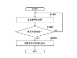
- FIG. 5 is a flowchart showing the procedure of warning processing executed by the control unit 101 of the own vehicle 100 according to the approaching state of the suspicious person according to this embodiment.
- the processing described below is realized, for example, by the CPU of the control unit 101 reading a program held in the ROM or the storage unit 102 into the RAM and executing the program.
- the number following S indicates the step number of each process.
- the approaching state of a suspicious person indicates a state of danger to the own vehicle 100 by a suspicious person.
- the control unit 101 of the own vehicle 100 executes authentication processing of an approaching person approaching the own vehicle 100, as described using FIG. Specifically, the control unit 101 transmits a signal for establishing short-range wireless communication using the key authentication communication device 136 within a predetermined distance range. Authentication information is obtained from the authentication key 220 and authentication processing is executed.
- the control unit 101 determines whether or not the authentication process with the authentication key 220 has succeeded. If the authentication process is successful, the process proceeds to S509, the control unit 101 proceeds to start control of the own vehicle 100, and ends this flowchart. On the other hand, if the authentication process has not succeeded, the control unit 101 identifies the approaching person as a suspicious person and advances the process to S503.
- the case where the authentication process is not successful means the case where the close person does not have the authentication key in the first place and the short-range wireless communication is not established, or the near-field wireless communication is established but the subsequent authentication process is performed. This includes the case where the owner of the own vehicle 100 cannot be determined to be the authorized owner.
- the control unit 101 determines whether or not an approaching person whose authentication processing has not succeeded has approached within a predetermined distance from the own vehicle 100, based on the output of the radar unit 16B. More specifically, the control unit 101 determines whether an approaching person identified as a suspicious person has approached within 3 m from the own vehicle 100 based on the output result of the radar 111, for example. If it approaches, the process proceeds to S504. On the other hand, if it is not approaching, the determination of S503 is repeated. If the person does not approach within the predetermined distance after the predetermined time has passed, or if the person moves away from the range of R2, it is determined that there is no possibility of identifying the suspicious person, and the repeated determination of S503 ends. You may
- the control unit 101 determines that the vehicle 100 may be in danger from a suspicious person.
- the possibility of danger indicates that there is an increased possibility that self-vehicle 100 will be stolen or mischievous by a suspicious person.
- the control unit 101 issues an alarm according to the first pattern. More specifically, the control unit 101 turns on the warning light using at least one of the lighting bodies such as the headlight 11, the taillight 117, and the blinker 115. FIG.
- the control unit 101 determines whether or not at least one of detection by the in-vehicle sensor 106 and input to the operator 105 has occurred. If it has not occurred, the determination of S506 is repeated periodically. Note that when a predetermined time has passed or when the approaching person has left the range of R1 or R2, it may be determined that there is no longer a possibility that the own vehicle 100 will be subjected to a criminal act, and the determination process may be terminated. . On the other hand, if either occurs, the process proceeds to S507, and the control unit 101 determines that the host vehicle 100 is under criminal activity, that is, is in danger.
- the control unit 101 issues an alarm with a second pattern different from the first pattern, and terminates the process. More specifically, the control unit 101 causes the horn 118 or the like to generate a warning sound, for example, in addition to or in place of the warning by the lamp body in the first pattern.
- the behavior of the suspicious person is monitored by switching the warning pattern using sound or light according to the approach state of the approaching person identified as the suspicious person to the own vehicle 100 . It is possible to raise awareness of the fact that It is desirable that the warning be continued until it is determined that there is no danger of a criminal act or a predetermined input is made.
- first pattern and second pattern do not necessarily correspond to the "first pattern” and “second pattern” described in the claims. . In this specification, the same applies to other terms, but “first”, “second”, and “third” merely indicate that they are different from each other.
- FIG. 6 is a flow chart showing a modification of the warning process of FIG.
- the processing described below is realized, for example, by the CPU of the control unit 101 reading a program held in the ROM or the storage unit 102 into the RAM and executing the program.
- the number following S indicates the step number of each process. Further, the same step numbers are assigned to the same processes as in FIG. 5, and the description thereof is omitted.
- the process proceeds to S601, the control unit 101 determines that it is a risk preparation time, and starts counting the number of occurrences.
- the danger preparation time indicates a state in which the possibility of danger to the own vehicle 100 is higher than the danger possibility time.
- the control unit 101 determines whether or not the number of occurrences of at least one of the detection by the in-vehicle sensor 106 and the input to the operator 105 has reached a predetermined number. If the predetermined number of times has been reached, the process proceeds to S507; otherwise, the determination of S602 is periodically repeated.
- control unit 101 determines that the host vehicle 100 is in danger, and thereafter executes the same processing as the processing in FIG.
- the warning was not issued when it was determined that it was a danger preparation time, but the warning may be issued at this timing as well.
- a warning sound may be generated continuously while blinking the body.
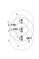
- FIG. 7 shows a diagram for explaining the relationship between the host vehicle 100 and the other vehicle 200 according to this embodiment.
- Circles R1 and R2 indicate a range of a predetermined radius from the vehicle 100.
- R1 is set between 5m and 20m, and R2 is set within 5m.
- a person 400 c indicates a suspicious person who has approached the own vehicle 100 .
- 200a to 200c denote other vehicles having imaging units such as cameras.
- own vehicle 100 transmits a signal informing the danger of own vehicle 100 within a predetermined distance according to the approaching state of a suspicious person to own vehicle 100 .
- the signal is transmitted, for example, within a range of R1, for example within a radius of 5 m to 20 m. Therefore, the signal transmitted from own vehicle 100 is received by each of other vehicles 200a, 200b, and 200c located within the range of R1.
- other vehicles located beyond the range R1 from own vehicle 100 cannot receive the signal from own vehicle 100.
- Own vehicle 100 transmits a signal in response to at least one of the approaching state of a suspicious person to own vehicle 100, that is, the danger potential state, danger preparatory state, and danger state.
- the own vehicle 100 transmits a signal indicating the danger possibility of the own vehicle 100 in the dangerous state, and a signal indicating that the own vehicle 100 is in danger (corresponding to the first signal) in the dangerous state.
- the own vehicle 100 transmits a signal (corresponding to a second signal) indicating that the own vehicle 100 is in a danger preparation state in the danger preparation state, and transmits a signal indicating that the own vehicle 100 is in the danger preparation state.
- a signal may be sent to indicate that there is.
- the other vehicles 200a to 200c control activation of their own imaging units according to the received signal. For example, when the other vehicles 200a to 200c receive the signal indicating the possibility of danger or the signal indicating the time of risk preparation, they activate the imaging unit to prepare for photographing, and when they receive the signal indicating the time of danger, You may make it start the imaging
- FIG. This allows for more accurate crime scene evidence to be recorded.
- the other vehicles 200a to 200c grasp the distance from the own vehicle 100 according to the signal strength of the received signal, and, for example, only when they determine that they are located within the range R2 from the own vehicle 100, shoot. you can go As a result, only other vehicles located relatively close to the host vehicle 100 can take pictures, and useless pictures can be reduced.
- the own vehicle 100 may change the transmission range according to the signal to be transmitted.
- the vehicle 100 may transmit signals within R1 during potential danger conditions and within R2 during danger conditions.
- FIG. 8 is a flow chart showing the procedure of warning processing executed by the control unit 101 of the own vehicle 100 according to the approaching state of the suspicious person according to this embodiment.
- the processing described below is realized, for example, by the CPU of the control unit 101 reading a program held in the ROM or the storage unit 102 into the RAM and executing the program.
- the number following S indicates the step number of each process. 5 and 6 are assigned the same step numbers, and descriptions thereof are omitted.
- S504 when an approaching person who has not been successfully authenticated approaches within a predetermined distance L1 from the own vehicle 100, the process proceeds to S801, and the control unit 101 determines that there is a possibility of danger and indicates the possibility of danger.
- a signal is sent, for example, within R1 to start counting the number of occurrences.
- the control unit 101 determines whether or not the number of occurrences of at least one of the detection by the in-vehicle sensor 106 and the input to the operator 105 has reached a predetermined number. If the predetermined number of times has been reached, the process proceeds to S802; otherwise, the determination of S602 is periodically repeated.
- control unit 101 determines that the host vehicle 100 is in danger, transmits a signal indicating the danger within the range of R1 or R2, and then executes the same processing as the processing in FIG.
- FIG. 9 is a flow chart showing a processing procedure of photographing processing of the other vehicle 200 according to this embodiment.
- the processing described below is realized, for example, by the CPU of the control unit 201 reading a program held in the ROM or the storage unit 202 into the RAM and executing the program.
- the number following S indicates the step number of each process.
- FIG. 8 the case where own vehicle 100 transmits a danger preliminary signal and a danger signal will be described. The same processing is performed when a danger possibility signal is received instead of the danger preliminary signal.
- control unit 201 receives a danger preliminary signal (or danger possibility signal) from the own vehicle 100 via the short-range wireless device 206. Subsequently, in S902, the control unit 201 activates at least one of the camera 208 of the imaging unit 204 and the drive recorder 209, and executes preparation processing for photographing.
- a danger preliminary signal or danger possibility signal
- the control unit 201 receives a danger signal from the own vehicle 100 via the short-range wireless device 206 . Subsequently, in S904, the control unit 201 starts shooting with the imaging unit 204 activated in S902. These imaging operations may be performed continuously for a predetermined period of time and periodically, or, for example, in the case of receiving a signal periodically, if the signal is not received for a predetermined period of time, the imaging may be terminated. The details of the determination of whether or not to end shooting will be described later.
- the control unit 201 When the shooting ends, the control unit 201 records the captured image data in the storage unit 202 in S905. Alternatively, it may be stored in a memory card (not shown) or the like. As a result, the memory card can be submitted to an investigative agency that investigates crimes, thereby improving the portability of data and effectively utilizing the storage area. Also, the control unit 201 may transmit the imaging data to the external device 211 via the data transmission unit 207 . Accordingly, the imaged data is held in the storage unit 212 of the external device 211, and the imaged data of each vehicle can be collectively managed.
- FIG. 10 is a flow chart showing a modification of the processing procedure when the own vehicle 100 transmits the danger signal. This flowchart shows the processing executed when the GPS 134 is powered off.
- the processing described below is realized, for example, by the CPU of the control unit 101 reading a program held in the ROM or the storage unit 102 into the RAM and executing the program.
- the number following S indicates the step number of each process.
- the control unit 101 determines whether or not the power to the GPS 134 was cut off according to a normal procedure.
- the normal procedure refers to a procedure in which the power supply is cut off by disabling the function of the GPS 134 according to a predetermined procedure on an operation panel (not shown) or the like.
- the illegal procedure is, for example, when a suspicious person steals the own vehicle 100, the power supply is cut off by physically disconnecting the power cable of the GPS 134 because the position of the vehicle after the theft cannot be grasped. indicates the case. Therefore, when the input of the position information from the GPS 134 stops without performing the regular procedure, the control unit 101 determines that the power supply to the GPS 134 has been cut off by a procedure different from the regular procedure. In that case, the process advances to S1002, and if it is determined that the normal procedure has been performed, this flowchart ends.
- the control unit 101 determines that the vehicle 100 is in danger by a suspicious person, transmits a signal indicating danger within the range of R1 or R2, and terminates this flowchart.
- the danger signal may be transmitted regardless of whether the suspicious person is identified, or the danger signal may be transmitted only when the suspicious person approaching the own vehicle 100 is identified.
- the other vehicle 200 that has received the emergency signal executes the processes of S903 to S905 described with reference to FIG.
- a suspicious person may disconnect the short-range wireless device 135 of the own vehicle 100 .
- the other vehicle 200 starts photographing when it stops receiving danger signals such as danger potential signals, danger preliminary signals, and danger signals periodically transmitted from the own vehicle 100. You may make it Thereby, even when the communication device is disconnected, it is possible to start shooting at an appropriate timing.
- FIG. 11 is a flow chart showing a modified example of the processing procedure of the photographing processing of the other vehicle 200. As shown in FIG. The processing described below is realized, for example, by the CPU of the control unit 201 reading a program held in the ROM or the storage unit 202 into the RAM and executing the program. The number following S indicates the step number of each process. Further, the same step numbers are attached to the same processing as in FIG. 9, and the description thereof is omitted.
- the control unit 201 receives the danger signal from the own vehicle 100. Subsequently, in S1102, the control unit 201 determines whether or not the distance to the own vehicle 100 is within the range of R2, for example, within 5 m. For example, the control unit 201 may determine the distance to the own vehicle 100 according to the signal strength received in S1101, or may measure the distance to the own vehicle 100 using a radar unit (not shown). If it is within the range of R2, proceed to S904; otherwise, proceed to S1103d. After proceeding to S904, the control unit 201 starts shooting and executes the same processing as in FIG.
- control unit 201 determines whether or not the distance to the own vehicle 100 is within the range of R1, for example, within 20m.
- the distance to own vehicle 100 is determined in the same manner as in S1102. If it is within the range of R1, the process proceeds to S902; otherwise, the flow chart ends.
- the control unit 201 activates the imaging unit to prepare for imaging, and returns the process to S1101. After that, when the danger signal is periodically received, the imaging unit is placed in a standby state until it is positioned within the range of R2. As described above, in the modification, after the other vehicle 200 receives a danger signal from the own vehicle 100 indicating danger, the distance to the own vehicle 100 is measured, and the imaging unit is activated according to the measurement result to set the vehicle in the standby state. or to start shooting.
- FIG. 12 explains the processing related to the end of the photographing processing of the host vehicle 100 and the other vehicle 200.
- FIG. FIG. 12A shows the processing after the host vehicle 100 has transmitted the danger signal
- FIG. 12B shows the processing after the other vehicle 200 receives the danger signal.
- the processing described below is realized by, for example, CPUs of the control units 101 and 201 reading programs held in the ROM and the storage units 102 and 202 into the RAM and executing the programs.
- the number following S indicates the step number of each process.
- the control unit 101 transmits a danger signal.
- the danger signal here corresponds to the signal transmitted in S801 or S802.
- the vehicle 100 may transmit a constant signal without switching the signal according to the approaching state of the suspicious person.
- the control unit 101 starts timing a predetermined time.
- the control unit 101 determines whether or not the time that started measuring in S1201 has passed a predetermined time, for example, one minute. If the predetermined time has elapsed, the process proceeds to S1203, and if not, the process returns to S1201 to continue transmitting the danger signal. In S1203, the control unit 101 stops transmitting the danger signal and ends this flowchart.
- a predetermined time for example, one minute.
- the control unit 201 receives a danger signal from the own vehicle 100, activates the imaging unit, and puts it in a standby state. Also, the control unit 201 starts timing a predetermined time. Subsequently, in S1212, the control unit 201 determines whether or not the clocked time has passed a predetermined time, for example, 1 minute. After the predetermined time has elapsed, the process advances to step S1213, and the control unit 201 starts photographing by the imaging unit.
- the own vehicle 100 stops transmitting the danger signal after a predetermined period of time has passed, and the other vehicle 200 receives the danger signal and starts shooting after a predetermined period of time has passed. Note that it is desirable that the other vehicle 200 starts shooting when it continues to receive the danger signal even after the predetermined time has passed. As a result, it is possible to reduce erroneous operations such as when the transmission of the danger signal is stopped when the danger is avoided.
- FIG. 13 is a flowchart showing another processing procedure of photographing processing by the other vehicle 200.
- the processing described below is realized, for example, by the CPU of the control unit 201 reading a program held in the ROM or the storage unit 202 into the RAM and executing the program.
- the number following S indicates the step number of each process. Further, the same step numbers are attached to the same processing as in FIG. 9, and the description thereof is omitted.
- the control unit 201 uses the signal strength of the danger signal received from the own vehicle 100 or a radar unit (not shown) to determine whether the distance from the own vehicle 100 is within a predetermined distance, for example, the range of R2. It is judged whether it is within 5m. If it is within the predetermined distance, the determination in S1301 is repeated. If it is not within the predetermined distance, for example, if it is determined that the other vehicle 200 is not within the range R2 from the own vehicle 100, the process proceeds to S1302.
- a predetermined distance for example, the range of R2.
- control unit 201 stops shooting. Subsequently, in S1303, the control unit 201 acquires position information using the GPS 205 and adds it to the imaging data captured after S1301. After that, in S905, the control unit 201 stores the imaging data in the storage unit 202, transmits it to the external device 211 via the data transmission unit 207, and ends this flowchart.
- FIG. 14 is a diagram showing the effect of the flowchart in FIG. 100a to 100c indicate own vehicles.
- the stolen own vehicle 100 is shown moving in the order of 100a, 100b, and 100c.
- 200a to 200c indicate other vehicles.
- Circles R1 and R2 indicate a range of a predetermined radius from the vehicle 100a-100c. For example, R1 is set between 5m and 20m, and R2 is set within 5m.
- Dotted lines R1 and R2 indicate radii from the host vehicle 100a.
- Solid lines R1 and R2 indicate radii from the host vehicle 100b.
- R1 and R2 indicated by dashed lines indicate radii from the host vehicle 100c.
- the other vehicle 200a When the control described above is performed using FIG. 13, the other vehicle 200a is located within the range indicated by the dotted line R2 at the position of the own vehicle 100a, so that it is photographed.
- the other vehicle 200a when the subject vehicle 100b or 100c moves to the position, the other vehicle 200a is not positioned within the range of R2 indicated by the solid line or the one-dot chain line, so the photographing ends.
- the other vehicle 200b shoots at the position of its own vehicle 100b, but finishes shooting at the position of its own vehicle 100c.
- the other vehicle 200c takes the image at the position of the own vehicle 100c, the image taking ends when the own vehicle 100c moves further and the other vehicle 200c is out of the range of R2.
- each of the other vehicles 200a to 200c obtains the positional information, adds it to the photographed data, stores it, and transmits it to the external device 211.
- each of the other vehicles 200a to 200c receives the danger signal, it determines the distance from the own vehicle 100 and determines the end of shooting. For example, when the imaging unit of the other vehicle 200 is provided in front of the vehicle, it is possible to photograph a predetermined range in the forward direction, but it is not possible to photograph positions beyond that range. In other words, since the other vehicle 200 has a limited imaging range, it is desirable to end the imaging by determining that the own vehicle 100 cannot be imaged when the distance from the own vehicle 100 is to some extent. It is desirable that this distance can be changed by setting based on the performance of the camera. If the shooting direction of the camera can be changed, it is possible to set a wider shooting range. By determining the end of photographing by the other vehicle 200 in this way, the control of the own vehicle 100 can be simplified and unnecessary photographing can be avoided.
- FIG. 15 explains processing related to the end of photographing processing of own vehicle 100 and other vehicle 200 .
- FIG. 15A shows processing when own vehicle 100 is determined to be in a dangerous state
- FIG. 15B shows processing after other vehicle 200 starts photographing.
- the processing described below is realized by, for example, CPUs of the control units 101 and 201 reading programs held in the ROM and the storage units 102 and 202 into the RAM and executing the programs.
- the number following S indicates the step number of each process.
- the control unit 101 determines that the host vehicle 100 is in danger by a suspicious person and transmits an emergency signal. Note that the determination of these dangerous states is the same as the control described with reference to FIG. 8, so description thereof will be omitted.
- the control unit 101 issues an alarm using the second pattern as described above.
- the control unit 101 determines whether the dangerous state of the own vehicle 100 is a dangerous state, a danger preparatory state, or a possible danger state. Repeat periodically. On the other hand, if it is determined that none of the dangerous states exist, the control unit 101 advances to S1506 and determines whether or not a predetermined time has elapsed. The predetermined time indicates the elapsed time since it was last determined to be one of the dangerous states. Five minutes, for example, is set as the predetermined time. If the predetermined time has not passed, the process returns to S1503, and if it is determined that the predetermined time has passed, the process proceeds to S1507. ) and terminate the process. In addition, since there is a possibility that the other vehicle 200 cannot receive the signal with one transmission, it is desirable to continuously transmit the danger evacuation signal for a predetermined period of time.
- the control unit 201 determines whether or not a retraction signal has been received after the start of imaging. Upon receiving the evacuation signal, the control unit 201 advances to S ⁇ b>1512 and acquires position information using the GPS 205 . Subsequently, in S1513, the control unit 201 attaches the acquired position information to the imaging data, transmits the imaging data to the external device 211, and ends the process. In this way, it may be determined whether or not the host vehicle 100 has escaped from a dangerous state, and if the host vehicle 100 has escaped, a signal indicating that fact may be transmitted to end the photographing of the other vehicle 200 .
- At least one in-vehicle sensor (106) that detects the state of the vehicle, at least one distance sensor (103) that measures the distance between the vehicle and other objects, and at least one sensor that operates the vehicle.
- a vehicle (100) comprising two operators (105), a wireless communication means (135) for transmitting a signal by wireless communication to one or more other vehicles; determination means (S502, S503, 101) for determining whether or not authentication by communication with the vehicle key is successful when the output of the at least one distance sensor indicates a person approaching the vehicle;
- the wireless communication means detects one or more other vehicles.
- a control means (S802, 101) for causing the other vehicle that receives the first signal to perform the first action.
- the first action is an operation of photographing at least one of a still image and a moving image by an imaging means provided in the other vehicle (S904).
- lamp bodies (11, 115, 117) that emit light; a sound generator (118) that emits sound;
- the control means is When at least one of the detection by the at least one in-vehicle sensor and the input to the at least one operation element occurs when the determining means determines that the authentication has failed, the lighting body and the sound generating device further (S508).
- the control means is When the determining means determines that the authentication has failed and the at least one distance sensor detects that the approaching person has approached the vehicle to a predetermined distance, the wireless communication means performs one or more The other vehicle is caused to transmit a second signal, and the other vehicle that has received the second signal is caused to perform a second action as a preparatory operation for the first action (S801).
- the signal can be switched and transmitted according to the dangerous state in more detail, and other vehicles that have received the signal can shoot at appropriate timing while suppressing battery consumption. . 5.
- the wireless communication means periodically transmits at least one of the first signal and the second signal (S801, S802, S1203).
- the second action is the activation operation of the imaging means provided in the other vehicle (S902).
- the signal can be switched and transmitted according to the dangerous state in more detail, and other vehicles that have received the signal can shoot at appropriate timing while suppressing battery consumption. .
- the control means is When the determining means determines that the authentication has failed and the at least one distance sensor detects that the approaching person has approached the vehicle within a predetermined distance, the light body and the sound generating device and (S505).
- the alarm pattern can be switched in more detail according to the dangerous state of the vehicle by the suspicious person, giving the suspicious person psychological surprise and enhancing the ability to deter crime. .
- the control means is before a predetermined time elapses after at least one of the detection by the at least one in-vehicle sensor and the input to the at least one operator occurs when the determination means determines that the authentication has failed
- the wireless communication means transmits the first signal to one or more other vehicles.
- the control means is When the determining means determines that the authentication has failed and at least one of the detection by the at least one in-vehicle sensor and the input to the at least one operator occurs, the lamp and An alarm is issued in a third pattern using at least one of the sound generating device, and if the number of occurrences reaches a predetermined number of times before the predetermined time elapses from the first occurrence, the alarm is issued in the first pattern.
- the alarm pattern can be switched in more detail according to the dangerous state of the vehicle by the suspicious person, giving the suspicious person psychological surprise and enhancing the ability to deter crime. .
- the first signal is transmitted to one or more other vehicles by the wireless communication means (S1001, S1002).
- the one or more other vehicles when the one or more other vehicles receive the first signal, the one or more other vehicles are located within a first distance range from the one or more other vehicles. is started (S1102, S904).
- other vehicles that have received the signal can start shooting at an appropriate timing, reduce battery consumption, and effectively utilize memory resources for recording image data.
- the imaging means provided in the one or more other vehicles starts photographing.
- the imaging means Shooting ends (S1301, S1302).
- control means controls the detection by the at least one vehicle-mounted sensor and the detection by the at least one vehicle-mounted sensor and the if no input is made to the at least one operator, causing the wireless communication means to transmit a third signal to one or more other vehicles (S1507); In the one or more other vehicles, when the third signal is received after the photographing by the photographing means is started, the photographing by the photographing means is finished (S1511).
- the captured image data is transferred to the external device via the network (S905).
- the imaging data can be reliably secured, and the crime after theft can be suitably analyzed.
- the position information at the time of photographing by the position information measuring means provided in the one or more other vehicles is acquired and transmitted. It is added to the imaging data (S1303, S1512).
- the camera can be activated and shooting can be started at appropriate timing, and crime prevention can be enhanced.
- the position information measuring means (205) for measuring the position of the vehicle is further provided,
- the transfer means adds position information at the time of photographing to the imaging data and transfers the imaging data (S1303, S1512).
- At least one in-vehicle sensor (106) that detects the state of the vehicle, at least one distance sensor (103) that measures the distance between the vehicle and other objects, and at least one operation that operates the vehicle.
- the first vehicle is a wireless communication means (135) for transmitting a signal by wireless communication to another vehicle; determining means (S502, S503, 101) for determining whether or not authentication by communication with the vehicle key is successful when the output of the at least one distance sensor indicates a person approaching the vehicle; When it is determined that the authentication has failed by the determination means, When at least one of the detection by the at least one in-vehicle sensor and the input to the at least one operator occurs when the determination means determines that the authentication has failed, the wireless communication means detects one or more other vehicles.
- control means for transmitting a first signal to and causing another vehicle that receives the first signal to perform a first action
- the second vehicle is an imaging means (204) for starting imaging upon receiving the first signal from the first vehicle; and transfer means (207) for transferring image data captured by the imaging means to an external device via a network.
Abstract
The present invention is a vehicle comprising at least one onboard sensor for detecting the state of the vehicle, at least one distance sensor for measuring the distance between the vehicle and another object, and at least one operator for operating the vehicle, the vehicle moreover comprising: a wireless communication means for transmitting a signal to one or more other vehicles by wireless communication; a determination means for determining whether authentication by communication with a key of the vehicle is successful when the output of the at least one distance sensor indicates an approacher approaching the vehicle; and a control means that, when it is determined by the determination means that the authentication has failed and detection by the at least one onboard sensor and/or input to the at least the one operator occurs, causes a first signal to be transmitted to the one or more other vehicles by the wireless communication means and causes the other vehicles that have received the first signal to perform a first action.
Description
本発明は車両及び防犯システムに関する。
The present invention relates to vehicles and security systems.
車両の盗難やいたずらに対する防犯性を高めるためには、車両自身がそのような行為を検出しつつ警報などの措置を行うことが望ましい。このような不審者や不正行為を検知する技術や、不審者や不正行為を検知した際に警告などにより盗難やいたずらを抑制する技術、盗難後に車両を発見する手掛かりを得る技術など様々な技術が提案されている。
In order to increase the security against vehicle theft and tampering, it is desirable for the vehicle itself to detect such acts and take measures such as issuing an alarm. There are various technologies such as technology to detect suspicious persons and fraudulent activities, technology to suppress theft and mischief by issuing warnings when a suspicious person or fraudulent activity is detected, and technology to obtain clues to find a vehicle after theft. Proposed.
例えば、特許文献1には、車体の振動を感知して盗難又は危害防止用の音声出力を行う車両用の盗難又は危害防止装置において、出力する音声を変更する技術が提案されている。また、特許文献2には、無線信号を受信した際に車両の正規ユーザでないと判定された場合であっても、周辺車両の正規ユーザから送信されたものと判断したときは、不審者の検出を無効とするセキュリティ装置について提案している。また、特許文献3には、運転する自己車両に接近する検知対象物を検知する検知システムにおいて、接近方向に応じて運転者にその方向から聞こえるよう音響システムを制御する技術が提案されている。
For example, Patent Literature 1 proposes a technique for changing the output sound in a vehicle anti-theft or harm prevention device that senses vehicle body vibration and outputs voice for theft or harm prevention. Further, in Patent Document 2, even if it is determined that the user of the vehicle is not an authorized user when the radio signal is received, when it is determined that the transmission is from an authorized user of a nearby vehicle, a suspicious person is detected. proposed a security device that disables Further, Patent Document 3 proposes, in a detection system for detecting a detection target approaching a driving own vehicle, a technique for controlling an acoustic system according to the direction of approach so that the driver can hear from that direction.
しかし、従来技術では警告音を切り替えることはできる技術や、自己車両に接近する検知対象物及びその接近方向を検知する技術は提案されているものの、一車両で行える防犯対策には限りがあり、自車両への接近者に対して他車両と協働して対策を行うことについては検討されていない。
However, although conventional technologies have proposed a technology for switching the warning sound and a technology for detecting a detection target approaching the own vehicle and its approaching direction, there is a limit to the crime prevention measures that can be performed by a single vehicle. Cooperating with other vehicles to take countermeasures against persons approaching the own vehicle has not been considered.
本発明の目的は、不審者による車両への危険の度合いに応じて、他車両と協働して対策を行うことにより新たな防犯の仕組みを提供することにある。
The purpose of the present invention is to provide a new crime prevention mechanism by cooperating with other vehicles to take measures according to the degree of danger to the vehicle by suspicious persons.
本発明によれば、車両の状態を検出する少なくとも1つの車載センサと、車両と他の物体との距離を計測する少なくとも1つの距離センサと、車両を操作する少なくとも1つの操作子と、を備える車両であって、
1以上の他車両へ無線通信による信号を送信する無線通信手段と、
前記少なくとも1つの距離センサの出力が前記車両への接近者を示す場合において、該車両の鍵との通信による認証が成功したか否かを判断する判断手段と、
前記判断手段によって認証が失敗したと判断された場合において、前記少なくとも1つの車載センサによる検知及び前記少なくとも1つの操作子への入力の少なくとも一方が発生すると、前記無線通信手段によって1以上の他車両に対して第1信号を送信させ、該第1信号を受信した他車両に第1アクションを行わせる制御手段と
を備えることを特徴とする。 According to the present invention, at least one in-vehicle sensor that detects the state of the vehicle, at least one distance sensor that measures the distance between the vehicle and other objects, and at least one operator that operates the vehicle are provided. a vehicle,
wireless communication means for transmitting a signal by wireless communication to one or more other vehicles;
determining means for determining whether or not authentication by communication with the vehicle key is successful when the output of the at least one distance sensor indicates a person approaching the vehicle;
When at least one of the detection by the at least one in-vehicle sensor and the input to the at least one operator occurs when the determination means determines that the authentication has failed, the wireless communication means detects one or more other vehicles. and control means for causing the other vehicle that receives the first signal to perform the first action.
本発明によれば、不審者による車両への危険の度合いに応じて、他車両と協働して対策を行うことにより新たな防犯の仕組みを提供できる。
According to the present invention, a new crime prevention mechanism can be provided by cooperating with other vehicles to take measures according to the degree of danger to the vehicle by the suspicious person.
本発明のその他の特徴及び利点は、添付図面を参照とした以下の説明により明らかになるであろう。なお、添付図面においては、同じ若しくは同様の構成には、同じ参照番号を付す。
Other features and advantages of the present invention will become apparent from the following description with reference to the accompanying drawings. In the accompanying drawings, the same or similar configurations are given the same reference numerals.
添付図面は明細書に含まれ、その一部を構成し、本発明の実施の形態を示し、その記述と共に本発明の原理を説明するために用いられる。
一実施形態に係る鞍乗型車両の右側の側面図。
図1の鞍乗型車両の正面図。
一実施形態に係る本防犯システムの制御構成を示すブロック図。
一実施形態に係る車両への接近者を検知する仕組みを説明する図。
第1の実施形態に係る自車両の警告処理の処理手順を示すフローチャート。
図5の変形例を示すフローチャート。
一実施形態に係る自車両と他車両との関係を示す図。
第2の実施形態に係る自車両の警告処理の処理手順を示すフローチャート。
第2の実施形態に係る他車両の撮影処理の処理手順を示すフローチャート。
危険時信号を送信する際の他の処理手順を示すフローチャート。
危険信号を受信した際の他車両の他の処理手順を示すフローチャート。
危険信号を受信した際の他車両の他の処理手順を示すフローチャート。
危険信号を受信した際の他車両の他の処理手順を示すフローチャート。
撮影処理の他車両の他の処理手順を示すフローチャート。
図13の処理による効果を説明する図。
撮影を終了する際の他車両の他の処理手順を示すフローチャート。
撮影を終了する際の他車両の他の処理手順を示すフローチャート。
The accompanying drawings, which are incorporated in and constitute a part of the specification, illustrate embodiments of the invention and, together with the description, serve to explain the principles of the invention.
1 is a right side view of a straddle-type vehicle according to an embodiment; FIG. FIG. 2 is a front view of the straddle-type vehicle of FIG. 1; 1 is a block diagram showing the control configuration of the security system according to one embodiment; FIG. The figure explaining the mechanism which detects the approaching person to the vehicle which concerns on one Embodiment. 4 is a flow chart showing a processing procedure of warning processing for own vehicle according to the first embodiment; 6 is a flowchart showing a modification of FIG. 5; The figure which shows the relationship between the own vehicle and other vehicles which concern on one Embodiment. 10 is a flowchart showing a processing procedure of warning processing for own vehicle according to the second embodiment; FIG. 11 is a flow chart showing a processing procedure of photographing processing of another vehicle according to the second embodiment; FIG. 4 is a flowchart showing another processing procedure when transmitting a danger signal; 4 is a flowchart showing another processing procedure of another vehicle when receiving a danger signal; 4 is a flowchart showing another processing procedure of another vehicle when receiving a danger signal; 4 is a flowchart showing another processing procedure of another vehicle when receiving a danger signal; 4 is a flow chart showing another processing procedure of another vehicle in the photographing process; 14A and 14B are diagrams for explaining the effect of the processing of FIG. 13; FIG. FIG. 10 is a flowchart showing another processing procedure of another vehicle when finishing photographing; FIG. FIG. 10 is a flowchart showing another processing procedure of another vehicle when finishing photographing; FIG.
以下、添付図面を参照して実施形態を詳しく説明する。なお、以下の実施形態は特許請求の範囲に係る発明を限定するものではなく、また実施形態で説明されている特徴の組み合わせの全てが発明に必須のものとは限らない。実施形態で説明されている複数の特徴のうち二つ以上の特徴は任意に組み合わされてもよい。また、同一若しくは同様の構成には同一の参照番号を付し、重複した説明は省略する。
Hereinafter, embodiments will be described in detail with reference to the accompanying drawings. It should be noted that the following embodiments do not limit the invention according to the claims, and not all combinations of features described in the embodiments are essential to the invention. Two or more of the features described in the embodiments may be combined arbitrarily. Also, the same or similar configurations are denoted by the same reference numerals, and redundant explanations are omitted.
各図において、矢印X、Y、Zは互いに直交する方向を示し、X方向は鞍乗型車両の前後方向、Y方向は鞍乗型車両の車幅方向(左右方向)、Z方向は上下方向を示す。鞍乗型車両の左、右は前進方向で見た場合の左、右である。以下、鞍乗型車両の前後方向の前方または後方のことを単に前方または後方と呼ぶ場合がある。また、鞍乗型車両の車幅方向(左右方向)の内側または外側のことを単に内側または外側と呼ぶことがある。
In each figure, arrows X, Y, and Z indicate directions orthogonal to each other, the X direction being the front-rear direction of the saddle-ride type vehicle, the Y direction being the vehicle width direction (horizontal direction) of the saddle-ride type vehicle, and the Z direction being the vertical direction. indicates The left and right sides of the straddle-type vehicle are the left and right sides when viewed in the forward direction. Hereinafter, the front or rear in the longitudinal direction of the straddle-type vehicle may simply be referred to as the front or rear. In addition, the inner side or the outer side in the vehicle width direction (horizontal direction) of the straddle-type vehicle may be simply referred to as the inner side or the outer side.
<第1の実施形態>
<鞍乗型車両の概要>
以下では本発明の第1の実施形態について説明する。図1は、本発明の一実施形態に係る鞍乗型車両1の右側の側面図、図2は鞍乗型車両1の正面図である。 <First Embodiment>
<Overview of straddle-type vehicle>
A first embodiment of the present invention will be described below. FIG. 1 is a right side view of a straddle-type vehicle 1 according to an embodiment of the present invention, and FIG. 2 is a front view of the straddle-type vehicle 1. As shown in FIG.
鞍乗型車両1は、長距離の移動に適したツアラー系の自動二輪車であるが、本発明は他の形式の自動二輪車を含む各種の鞍乗型車両に適用可能であり、また、内燃機関を駆動源とする車両のほか、モータを駆動源とする電動車両にも適用可能である。以下、鞍乗型車両1のことを車両1と呼ぶ場合がある。また、本実施形態では、車両の一例として二輪の鞍乗型車両を例に説明するが、本発明を限定する意図はなく例えば四輪駆動車両など種々の車両に適用可能である。
The straddle-type vehicle 1 is a tourer-type motorcycle suitable for long-distance travel, but the present invention is applicable to various straddle-type vehicles including other types of motorcycles. It can be applied to an electric vehicle using a motor as a drive source as well as a vehicle using a motor as a drive source. The straddle-type vehicle 1 may be referred to as the vehicle 1 hereinafter. Further, in the present embodiment, a two-wheel saddle type vehicle will be described as an example of a vehicle, but the present invention is not intended to be limited and can be applied to various vehicles such as a four-wheel drive vehicle.
車両1は、前輪FWと後輪RWとの間にパワーユニット2を備える。パワーユニット2は本実施形態の場合、水平対向六気筒のエンジン21と変速機22とを含む。変速機22の駆動力は不図示のドライブシャフトを介して後輪RWに伝達され、後輪RWを回転する。
The vehicle 1 has a power unit 2 between the front wheels FW and the rear wheels RW. In this embodiment, the power unit 2 includes a horizontally opposed six-cylinder engine 21 and a transmission 22 . The driving force of the transmission 22 is transmitted to the rear wheels RW via a drive shaft (not shown) to rotate the rear wheels RW.
パワーユニット2は車体フレーム3に支持されている。車体フレーム3は、X方向に延設された左右一対のメインフレーム31を含む。メインフレーム31の上方には、燃料タンク5やエアクリーナボックス(不図示)が配置されている。燃料タンク5の前方には、ライダに対して各種の情報を表示する電子画像表示装置等を備えたメータパネルMPが設けられている。
The power unit 2 is supported by the body frame 3. The body frame 3 includes a pair of left and right main frames 31 extending in the X direction. A fuel tank 5 and an air cleaner box (not shown) are arranged above the main frame 31 . In front of the fuel tank 5, there is provided a meter panel MP equipped with an electronic image display device for displaying various information to the rider.
メインフレーム31の前側端部には、ハンドル8によって回動される操向軸(不図示)を回動自在に支持するヘッドパイプ32が設けられている。メインフレーム31の後端部には、左右一対のピボットプレート33が設けられている。ピボットプレート33の下端部とメインフレーム31の前端部とは左右一対のロワアーム(不図示)により接続され、パワーユニット2はメインフレーム31とロワアームとに支持される。メインフレーム31の後端部には、また、後方へ延びる左右一対のシートレール(不図示)が設けられており、シートレールはライダが着座するシート4aや同乗者が着座するシート4b及びリアトランク7b等を支持する。
A head pipe 32 that rotatably supports a steering shaft (not shown) rotated by the handle 8 is provided at the front end of the main frame 31 . A pair of left and right pivot plates 33 are provided at the rear end of the main frame 31 . A lower end portion of the pivot plate 33 and a front end portion of the main frame 31 are connected by a pair of left and right lower arms (not shown), and the power unit 2 is supported by the main frame 31 and the lower arms. A pair of left and right seat rails (not shown) extending rearward are provided at the rear end of the main frame 31. The seat rails are a seat 4a on which a rider sits, a seat 4b on which a fellow passenger sits, and a rear trunk. 7b etc. are supported.
ピボットプレート33には、前後方向に延びるリアスイングアーム(不図示)の前端部が揺動自在に支持されている。リアスイングアームは、上下方向に揺動可能とされ、その後端部に後輪RWが支持されている。後輪RWの下部側方には、エンジン21の排気を消音する排気マフラ6がX方向に延設されている。後輪RWの上部側方には左右のサドルバック7aが設けられている。
The pivot plate 33 swingably supports the front end of a rear swing arm (not shown) extending in the front-rear direction. The rear swing arm is vertically swingable, and supports the rear wheel RW at its rear end. An exhaust muffler 6 that muffles exhaust noise from the engine 21 extends in the X direction below the rear wheel RW. Left and right saddlebags 7a are provided on the upper side of the rear wheel RW.
メインフレーム31の前端部には、前輪FWを支持するフロントサスペンション機構9が構成されている。フロントサスペンション機構9は、アッパリンク91、ロワリンク92、フォーク支持体93、クッションユニット94、左右一対のフロントフォーク95を含む。
A front suspension mechanism 9 that supports the front wheels FW is configured at the front end of the main frame 31 . The front suspension mechanism 9 includes an upper link 91 , a lower link 92 , a fork support 93 , a cushion unit 94 and a pair of left and right front forks 95 .
アッパリンク91及びロワリンク92は、それぞれメインフレーム31の前端部に上下に間隔を開けて配置されている。アッパリンク91及びロワリンク92の各後端部は、メインフレーム31の前端部に設けられた支持部31a、31bに揺動自在に連結されている。アッパリンク91及びロワリンク92の各前端部は、フォーク支持体93に揺動自在に連結されている。アッパリンク91及びロワリンク92は、それぞれ前後方向に延びるとともに実質的に平行に配置されている。
The upper link 91 and the lower link 92 are arranged at the front end of the main frame 31 with a vertical gap therebetween. Rear ends of the upper link 91 and the lower link 92 are pivotably connected to support portions 31 a and 31 b provided at the front end of the main frame 31 . Front ends of the upper link 91 and the lower link 92 are pivotably connected to a fork support 93 . The upper link 91 and the lower link 92 each extend in the front-rear direction and are arranged substantially in parallel.
クッションユニット94は、コイルスプリングにショックアブソーバを挿通した構造を有し、その上端部は、メインフレーム31に揺動自在に支持されている。クッションユニット94の下端部は、ロワリンク92に揺動自在に支持されている。
The cushion unit 94 has a structure in which a shock absorber is inserted through a coil spring, and its upper end is supported by the main frame 31 so as to be swingable. A lower end portion of the cushion unit 94 is swingably supported by the lower link 92 .
フォーク支持体93は、筒状をなすとともに後傾している。フォーク支持体93の上部前部には、アッパリンク91の前端部が回動可能に連結されている。フォーク支持体93の下部後部には、ロワリンク92の前端部が回動可能に連結されている。
The fork support 93 is cylindrical and tilts backward. The front end of the upper link 91 is rotatably connected to the upper front portion of the fork support 93 . A front end portion of the lower link 92 is rotatably connected to the lower rear portion of the fork support 93 .
フォーク支持体93には操舵軸96がその軸回りに回転自在に支持されている。操舵軸96はフォーク支持体93を挿通する軸部(不図示)を有する。操舵軸96の下端部にはブリッジ(不図示)が設けられており、このブリッジには左右一対のフロントフォーク95が支持されている。前輪FWはフロントフォーク95に回転自在に支持されている。操舵軸96の上端部は、リンク97を介して、ハンドル8によって回動される操向軸(不図示)に連結されている。ハンドル8の操舵によって操舵軸96が回転し、前輪FWが操舵される。
A steering shaft 96 is rotatably supported on the fork support 93 about its axis. The steering shaft 96 has a shaft portion (not shown) through which the fork support 93 is inserted. A bridge (not shown) is provided at the lower end of the steering shaft 96, and a pair of left and right front forks 95 are supported by this bridge. The front wheel FW is rotatably supported by the front fork 95 . The upper end of the steering shaft 96 is connected via a link 97 to a steering shaft (not shown) rotated by the handle 8 . Steering of the steering wheel 8 rotates the steering shaft 96 to steer the front wheels FW.
車両1は、前輪FWを制動するブレーキ装置19Fと後輪RWを制動するブレーキ装置19Fとを備える。ブレーキ装置19F、19Rはブレーキレバー8a又はブレーキペダル8bに対するライダの操作により作動可能に構成されている。ブレーキ装置19F、19Rは、例えば、ディスクブレーキである。ブレーキ装置19F、19Rを区別しない場合は、これらを総称してブレーキ装置19と呼ぶ。
The vehicle 1 includes a brake device 19F that brakes the front wheels FW and a brake device 19F that brakes the rear wheels RW. The brake devices 19F and 19R are configured to be operable by the rider's operation of the brake lever 8a or the brake pedal 8b. Brake devices 19F and 19R are, for example, disc brakes. When not distinguishing between the brake devices 19F and 19R, they are collectively referred to as the brake device 19. As shown in FIG.
車両1の前部には、車両1の前方に光を照射するヘッドライト11が配置されている。本実施形態のヘッドライト11は右側の光照射部11Rと、左側の光照射部11Lとを左右対称に備える二眼タイプのヘッドライトユニットである。しかし、一眼タイプや三眼タイプのヘッドライユニット、或いは、左右非対称の二眼タイプのヘッドライトユニットも採用可能である。
A headlight 11 that emits light in front of the vehicle 1 is arranged in the front part of the vehicle 1 . The headlight 11 of the present embodiment is a twin-lens type headlight unit that includes a right light irradiation section 11R and a left light irradiation section 11L symmetrically. However, a single-lens type headlight unit, a three-lens type headlight unit, or a left-right asymmetric two-lens type headlight unit can also be employed.
車両1の前部はフロントカウル12で覆われ、車両1の前側の側部は左右一対のサイドカウル14で覆われている。フロントカウル12の上方にはスクリーン13が配置されている。スクリーン13は走行中にライダが受ける風圧を軽減する風防であり、例えば、透明な樹脂部材で形成されている。
The front part of the vehicle 1 is covered with a front cowl 12, and the front side part of the vehicle 1 is covered with a pair of left and right side cowls 14. A screen 13 is arranged above the front cowl 12 . The screen 13 is a windshield that reduces the wind pressure applied to the rider during running, and is made of, for example, a transparent resin member.
フロントカウル12の側方には左右一対のサイドミラーユニット15が配置されている。サイドミラーユニット15にはライダが後方を視認するためのサイドミラー(不図示)が支持されている。
A pair of left and right side mirror units 15 are arranged on the sides of the front cowl 12 . A side mirror (not shown) is supported by the side mirror unit 15 so that the rider can visually recognize the rear.
本実施形態の場合、フロントカウル12は、カウル部材121~123により構成されている。カウル部材121はY方向に延在してフロントカウル12の本体を構成し、カウル部材122はカウル部材121の上側の部分を構成している。カウル部材123はカウル部材121から下方向に離間して配設されている。
In the case of this embodiment, the front cowl 12 is composed of cowl members 121-123. The cowl member 121 extends in the Y direction to constitute the main body of the front cowl 12 , and the cowl member 122 constitutes the upper portion of the cowl member 121 . The cowl member 123 is spaced downward from the cowl member 121 .
カウル部材121とカウル部材123との間、及び、左右一対のサイドカウル14の間に、ヘッドライト11を露出させる開口が形成され、この開口の上縁はカウル部材121により画定され、下縁はカウル部材123により画定され、左右の側縁はサイドカウル14で画定される。
Between the cowl member 121 and the cowl member 123 and between the pair of left and right side cowls 14, an opening is formed to expose the headlight 11. The upper edge of this opening is defined by the cowl member 121, and the lower edge is defined by the cowl member 121. It is defined by the cowl member 123 and the left and right side edges are defined by the side cowls 14 .
フロントカウル12の背後には車両1の前方の状況を検知する検知デバイスとしてとして撮像ユニット16A及びレーダーユニット16Bが配置されている。レーダーユニット16Bは例えばミリ波レーダである。撮像ユニット16AはCCDイメージセンサやCMOSイメージセンサ等の撮像素子と、レンズ等の光学系とを含み、車両1の前方の画像を撮像する。撮像ユニット16Aはフロントカウル12の上部を構成するカウル部材122の背後に配置されている。カウル部材122には、これを貫通する開口122aが形成されており、撮像ユニット16Aは開口122aを通して車両1の前方の画像を撮像する。
An imaging unit 16A and a radar unit 16B are arranged behind the front cowl 12 as detection devices for detecting the situation in front of the vehicle 1. The radar unit 16B is, for example, a millimeter wave radar. The image pickup unit 16A includes an image pickup device such as a CCD image sensor or a CMOS image sensor and an optical system such as a lens, and picks up an image in front of the vehicle 1 . The imaging unit 16A is arranged behind a cowl member 122 forming the upper portion of the front cowl 12. As shown in FIG. An opening 122a is formed through the cowl member 122, and the imaging unit 16A captures an image in front of the vehicle 1 through the opening 122a.
レーダーユニット16Bはカウル部材121の背後に配置されている。カウル部材121の存在により、車両1の正面視で検知ユニット(外界監視機器)16の存在を目立たなくすることができ、車両1の外観が悪化することを回避することができる。カウル部材121は樹脂等、電磁波の透過が可能な材料で構成される。
The radar unit 16B is arranged behind the cowl member 121. Due to the existence of the cowl member 121, the presence of the detection unit (external environment monitoring device) 16 can be made inconspicuous when viewed from the front of the vehicle 1, and deterioration of the appearance of the vehicle 1 can be avoided. The cowl member 121 is made of a material, such as resin, through which electromagnetic waves can pass.
撮像ユニット16A及びレーダーユニット16Bは、車両正面視でフロントカウル12のY方向の中央部に配置されている。撮像ユニット16A及びレーダーユニット16Bを車両1のY方向の中央部に配置することで、車両1の前方の左右に、より広い撮像範囲、検知範囲を得ることができ、車両1の前方の状況をより見落としなく検知できる。また、一つの撮像ユニット16A及び一つのレーダーユニット16Bにより車両1の前方を、左右均等に監視することができることから、撮像ユニット16A及びレーダーユニット16Bをそれぞれ複数設けずに、一つずつ設けた構成において、特に有利である。
The imaging unit 16A and the radar unit 16B are arranged in the center of the front cowl 12 in the Y direction when viewed from the front of the vehicle. By arranging the imaging unit 16A and the radar unit 16B at the center of the vehicle 1 in the Y direction, it is possible to obtain a wider imaging range and a wider detection range on the left and right in front of the vehicle 1, so that the situation in front of the vehicle 1 can be obtained. It can be detected without oversight. In addition, since one imaging unit 16A and one radar unit 16B can uniformly monitor the front of the vehicle 1 on the left and right sides, a configuration in which one imaging unit 16A and one radar unit 16B are provided instead of a plurality of each is provided. It is particularly advantageous in
<防犯システムの制御構成>
図3は本実施形態に係る防犯システムの制御構成を示すブロック図であり、後述する説明との関係で必要な構成のみが図示されている。本システムは、車両1に相当する自車両100と、1以上の他車両200と、外部機器211とを含んで構成される。認証キー220は、自車両100を起動するためのキーであり、自車両100に接近すると、自車両100との間で任意の近距離無線通信が行われ、自車両100の正規のユーザか否かを判断するための認証が行われる。 <Control configuration of security system>
FIG. 3 is a block diagram showing the control configuration of the security system according to this embodiment, and shows only the configuration necessary in relation to the description that will be given later. This system includes avehicle 100 corresponding to the vehicle 1 , one or more other vehicles 200 , and an external device 211 . The authentication key 220 is a key for activating the own vehicle 100. When the own vehicle 100 approaches, arbitrary short-range wireless communication is performed with the own vehicle 100 to determine whether the user of the own vehicle 100 is an authorized user. Authentication is performed to determine whether
図3は本実施形態に係る防犯システムの制御構成を示すブロック図であり、後述する説明との関係で必要な構成のみが図示されている。本システムは、車両1に相当する自車両100と、1以上の他車両200と、外部機器211とを含んで構成される。認証キー220は、自車両100を起動するためのキーであり、自車両100に接近すると、自車両100との間で任意の近距離無線通信が行われ、自車両100の正規のユーザか否かを判断するための認証が行われる。 <Control configuration of security system>
FIG. 3 is a block diagram showing the control configuration of the security system according to this embodiment, and shows only the configuration necessary in relation to the description that will be given later. This system includes a
自車両100は制御部(ECU)101、記憶部102、外界監視機器103、音光発生機器104、操作子105、車載センサ106、及び外部通信機器107を備える。外界監視機器103は、例えばレーダー111及びレーザー112を含むレーダーユニット16Bと、カメラ113及びドライブレコーダー114を含む撮像ユニット16Aとを備える。音光発生機器104は、例えばウィンカー115、ヘッドライト11、テールライト117、及びホーン118を含む。操作子105は、例えばシフトペダル119、ブレーキペダル8B、ブレーキレバー8A、クラッチレバー122、アクセルグリップ123、メインスイッチ124、車両機能操作スイッチ125、ウィンカスイッチ126、ホーンスイッチ127、サイドスタンド128、メインスタンド129、及びディマースイッチ130を含む。車載センサ106は、例えば加速度センサ131、角度センサ132、及び車輪速センサ133を含む。外部通信機器107は、例えばGPS134、近距離無線機器135、及びキー認証通信機器136を含む。もちろん各コンポーネントは、他の構成を含んでもよい。
The host vehicle 100 includes a control unit (ECU) 101, a storage unit 102, an external monitoring device 103, a sound and light generating device 104, an operator 105, an in-vehicle sensor 106, and an external communication device 107. The external monitoring device 103 includes, for example, a radar unit 16B including a radar 111 and a laser 112, and an imaging unit 16A including a camera 113 and a drive recorder 114. The sound and light generating devices 104 include, for example, turn signals 115, headlights 11, taillights 117, and horns 118. FIG. The operators 105 include, for example, a shift pedal 119, a brake pedal 8B, a brake lever 8A, a clutch lever 122, an accelerator grip 123, a main switch 124, a vehicle function operation switch 125, a winker switch 126, a horn switch 127, a side stand 128, and a main stand 129. , and a dimmer switch 130 . The in-vehicle sensors 106 include an acceleration sensor 131, an angle sensor 132, and a wheel speed sensor 133, for example. External communication devices 107 include GPS 134, near field wireless device 135, and key authentication communication device 136, for example. Of course, each component may include other configurations.
制御部101は、CPUに代表されるプロセッサを含む。記憶部102にはプロセッサが実行するプログラムやプロセッサが処理に使用するデータ等が格納される。なお、記憶部102は制御部101の内部に組み込まれてもよい。制御部101は、他のコンポーネント102~107とバス等の信号線で接続され、信号を送受することができ、自車両100の全体を制御する。
The control unit 101 includes a processor represented by a CPU. The storage unit 102 stores programs executed by the processor, data used by the processor for processing, and the like. Note that the storage unit 102 may be incorporated inside the control unit 101 . The control unit 101 is connected to other components 102 to 107 via signal lines such as buses, can transmit and receive signals, and controls the vehicle 100 as a whole.
例えば、制御部101は、外界監視機器103のレーダーユニット16Bの検知結果を取得して、自車両100の周辺の物標、道路状態を常時認識するとともに、自車両100に接近する物体を検知することができる。また、制御部101は、撮像ユニット16Aを用いて、走行中の道路状態や、接近物等を撮影し記録することができる。制御部101は、撮像ユニット16Aによって撮像された撮像データを記憶部102へ格納し、又不図示の外部通信機器を用いて外部機器へ送信することもできる。また、制御部101は、GPS134、近距離無線機器135、及びキー認証通信機器136を介して、各種情報を取得する。GPS134は、自車両100の現在位置を取得する。近距離無線機器135は、近距離無線通信を介して、後述する自車両100の危険状態に従った信号を所定距離内で送信する。近距離無線通信は、例えば、無線LAN(Wi-Fi)やBluetooth、NFCや赤外線通信など、所定範囲内で通信可能な通信方法であればよい。通信範囲としては、例えば、自車両100から例えば半径5m~20mを含む領域として設定されうる。当該信号は、自車両100から所定範囲内に位置する1以上の他車両200によって受信される。また、制御部101は、キー認証通信機器136を介して自車両100に接近してくる接近者が所有していると思われる認証キー(鍵)220と近距離無線通信を行い、当該認証キー220を保持するユーザが自車両100の正規の所有者であるユーザかどうかの認証を実行する。キー認証通信機器136と認証キー220との間の近距離無線通信は近距離無線機器135と同様の通信方法であってもよいし、そうでなくてもよい。
For example, the control unit 101 acquires the detection result of the radar unit 16B of the external monitoring device 103, constantly recognizes targets and road conditions around the vehicle 100, and detects objects approaching the vehicle 100. be able to. In addition, the control unit 101 can use the imaging unit 16A to photograph and record road conditions, approaching objects, etc. during travel. The control unit 101 can store image data captured by the imaging unit 16A in the storage unit 102, and can also transmit the data to an external device using an external communication device (not shown). Also, the control unit 101 acquires various information via the GPS 134 , the short-range wireless device 135 , and the key authentication communication device 136 . GPS 134 acquires the current position of host vehicle 100 . The short-range wireless device 135 transmits a signal according to the danger state of the own vehicle 100, which will be described later, within a predetermined distance via short-range wireless communication. Near-field wireless communication may be any communication method that enables communication within a predetermined range, such as wireless LAN (Wi-Fi), Bluetooth, NFC, and infrared communication. The communication range can be set as an area including a radius of 5 m to 20 m from the own vehicle 100, for example. The signal is received by one or more other vehicles 200 located within a predetermined range from host vehicle 100 . Further, the control unit 101 performs short-range wireless communication with an authentication key (key) 220 believed to be possessed by an approaching person approaching the vehicle 100 via the key authentication communication device 136, and 220 is authenticated as to whether or not the user is the authorized owner of own vehicle 100 . The short-range wireless communication between the key authentication communication device 136 and the authentication key 220 may or may not be the same communication method as the short-range wireless device 135 .
制御部101は、操作子105に含まれる各アクチュエータを制御可能である。また、本実施形態の場合、制御部101は後述する不審者による自車両100への危険状態を検知するために各アクチュエータへの入力を監視する。さらに、制御部101は、各種の車載センサ106による検知結果に基づいて不審者による自車両100への危険状態を検知する。ここで、不審者による自車両100への危険状態とは、キー認証通信機器136を介した認証が失敗した接近者、即ち不審者による自車両100への犯行の程度や可能性を示すものである。例えば、本実施形態において危険状態とは、上記程度の違いに応じて、危険可能性時、危険予備時、危険時、及び危険退避時に区分される。詳細については後述する。
The control unit 101 can control each actuator included in the manipulator 105 . Further, in the case of the present embodiment, the control unit 101 monitors inputs to each actuator in order to detect a dangerous state of the own vehicle 100 by a suspicious person, which will be described later. Furthermore, the control unit 101 detects a dangerous state of the vehicle 100 by a suspicious person based on the detection results of various vehicle-mounted sensors 106 . Here, the dangerous state of the vehicle 100 by a suspicious person indicates the degree or possibility of a crime against the vehicle 100 by an approaching person whose authentication via the key authentication communication device 136 has failed, that is, a suspicious person. be. For example, in this embodiment, the dangerous state is classified into possible danger, danger preparation, danger, and danger avoidance according to the difference in degree. Details will be described later.
次に、他車両200の構成について説明する。他車両200は、自車両100の位置から所定範囲内の1以上の車両を示すものであり、各車両は種々の構成を有するものであるが、ここでは本実施形態と実施する上で必須の構成のみを説明する。したがって、他車両200はここで説明する構成に加えて他の構成を含みうるものである。他車両200は、制御部201、記憶部202、外部通信機器203、撮像ユニット204を備える。外部通信機器203には、GPS205、近距離無線機器206、及びデータ送信部207を含む。撮像ユニット204は、カメラ208及びドライブレコーダー209を含む。
Next, the configuration of the other vehicle 200 will be explained. The other vehicle 200 indicates one or more vehicles within a predetermined range from the position of the own vehicle 100, and each vehicle has various configurations. Only the configuration will be explained. Therefore, other vehicle 200 may include other configurations in addition to the configuration described here. Other vehicle 200 includes control unit 201 , storage unit 202 , external communication device 203 , and imaging unit 204 . The external communication device 203 includes a GPS 205 , a short-range wireless device 206 and a data transmission section 207 . Imaging unit 204 includes camera 208 and drive recorder 209 .
制御部201は、CPUに代表されるプロセッサを含む。記憶部202にはプロセッサが実行するプログラムやプロセッサが処理に使用するデータ等が格納される。なお、記憶部202は制御部201の内部に組み込まれてもよい。制御部201は、他のコンポーネント203、204とバス等の信号線で接続され、信号を送受することができ、他車両200の全体を制御する。
The control unit 201 includes a processor represented by a CPU. The storage unit 202 stores programs executed by the processor, data used by the processor for processing, and the like. Note that the storage unit 202 may be incorporated inside the control unit 201 . The control unit 201 is connected to other components 203 and 204 via signal lines such as buses, can transmit and receive signals, and controls the other vehicle 200 as a whole.
制御部201は、撮像ユニット204によって撮像された撮像データを記憶部202へ格納し、又外部通信機器203のデータ送信部207を用いて広域ネットワークを介して外部機器211へ送信することもできる。また、制御部201は、GPS205、及び近距離無線機器206を介して、各種情報を取得する。GPS205は、他車両200の現在位置を取得する。例えば、撮像ユニット204のカメラ208で撮影を行った際の他車両200の位置を取得し、当該撮像データに位置情報を付与することができる。近距離無線機器206は、近距離無線通信を介して、自車両100から送信された危険状態に従った信号を受信する。近距離無線通信は、例えば、無線LAN(Wi-Fi)やBluetooth、NFCや赤外線通信など、所定範囲内で通信可能な通信方法であればよい。通信範囲としては、例えば、他車両200から例えば半径5m~20mを含む領域として設定されうる。
The control unit 201 can store the imaging data captured by the imaging unit 204 in the storage unit 202, and can also transmit the data to the external device 211 via the wide area network using the data transmission unit 207 of the external communication device 203. Also, the control unit 201 acquires various types of information via the GPS 205 and the short-range wireless device 206 . GPS 205 acquires the current position of other vehicle 200 . For example, it is possible to acquire the position of the other vehicle 200 when the camera 208 of the imaging unit 204 takes an image, and add the position information to the imaging data. The short-range wireless device 206 receives a signal according to the dangerous state transmitted from the own vehicle 100 via short-range wireless communication. Near-field wireless communication may be any communication method that enables communication within a predetermined range, such as wireless LAN (Wi-Fi), Bluetooth, NFC, and infrared communication. As the communication range, for example, an area including a radius of 5 m to 20 m from the other vehicle 200 can be set.
外部機器211は、各車両から送信された撮像データなどの撮影現場に関するデータを広域ネットワークを介して受信し、データ記憶部212に記憶する。データ記憶部212に記憶されたデータは後に所定機関において犯行を解析及び調査するために使用されるものである。
The external device 211 receives, via the wide area network, data relating to the shooting site, such as image data transmitted from each vehicle, and stores the data in the data storage unit 212 . The data stored in the data storage unit 212 is later used by a predetermined agency to analyze and investigate crimes.
<接近者の検知>
図4は本実施形態に係る自車両100に対する接近者を検知する仕組みを説明する図を示す。R1、R2の円は自車両100から所定半径の範囲を示す。例えばR1は5m~20mの間に設定され、R2は5m以内に設定される。400a~400cは自車両100へ矢印方向に接近している人物を表す。 <Detection of approaching person>
FIG. 4 shows a diagram for explaining a mechanism for detecting an approaching person to theown vehicle 100 according to this embodiment. Circles R1 and R2 indicate a range of a predetermined radius from the vehicle 100. FIG. For example, R1 is set between 5m and 20m, and R2 is set within 5m. 400a to 400c represent persons approaching the own vehicle 100 in the direction of the arrow.
図4は本実施形態に係る自車両100に対する接近者を検知する仕組みを説明する図を示す。R1、R2の円は自車両100から所定半径の範囲を示す。例えばR1は5m~20mの間に設定され、R2は5m以内に設定される。400a~400cは自車両100へ矢印方向に接近している人物を表す。 <Detection of approaching person>
FIG. 4 shows a diagram for explaining a mechanism for detecting an approaching person to the
自車両100は、410に示すように、レーダー111やレーザー112を用いて自車両100へ接近する物体を検知する。レーダー111やレーザー112の性能にもよるがR1、例えば自車両100から半径20mを超える場所に位置する人物400aも検知することができる。なお、人物400aの位置では、自車両100への接近者とは判断されない。
As indicated by 410, own vehicle 100 uses radar 111 and laser 112 to detect objects approaching own vehicle 100. Depending on the performance of the radar 111 and laser 112, R1, for example, a person 400a located at a location exceeding a radius of 20 m from the own vehicle 100 can also be detected. At the position of person 400 a , it is not determined that the person is approaching vehicle 100 .
人物400bは、R1の範囲内であって、R2の範囲外、例えば自車両から5mから20mの範囲内に位置する人物を示す。なお、自車両100は人物400bについてもR1の範囲内に侵入したタイミングですぐに接近者とは判断しない。これは、自車両100の横を通り過ぎる人物等を自車両100への接近者として誤検知することを防止するためである。また、R1の範囲内であって、R2の範囲外の人物400bについては基本的には接近者と判断しない。ただし、R1の範囲内に侵入した人物400bが所定時間内に自車両100との距離が縮まるなどの移動を行う場合には接近者と判断してもよい。
A person 400b indicates a person located within the range of R1 but outside the range of R2, for example, within the range of 5m to 20m from the own vehicle. Note that the own vehicle 100 does not immediately judge the person 400b as an approaching person at the timing when the person 400b enters the range of R1. This is to prevent erroneous detection of a person or the like passing by the vehicle 100 as a person approaching the vehicle 100 . Also, the person 400b who is within the range of R1 but out of the range of R2 is basically not judged as an approaching person. However, if the person 400b who has entered the range of R1 moves within a predetermined period of time, such as by shortening the distance from the own vehicle 100, it may be determined as an approaching person.
人物400cはR2の範囲内、例えば自車両から5m以内に位置する人物を示す。自車両100は人物がR2の範囲内に侵入すると接近者と判断する。さらに、自車両100は、接近者と判断すると、キー認証通信機器136を介して人物400cが所持しているであろう認証キー220と近距離無線通信を行い当該接近者が自車両100の正規の所有者であるか否かの認証を実施する。ここで、人物400cが認証キー220を所持していない場合は、そもそも認証キー220から認証情報を取得することができず、認証処理は失敗する。このような場合においては自車両100は、接近者である人物400cを不審者と判断する。なお、これらの近距離無線通信を用いた認証処理は、接近者を特定したことをトリガとして行われてもよい。一方、自動的に認証処理が実行されてもよく、当該近距離無線通信の範囲をR2の範囲内、例えば5m以内に設定し、近距離無線通信を確立するための信号を常時発信する構成であってもよい。これにより、例えば自車両100の周囲に障害物があることによってレーダー111等によって接近者を検知できない場合などにおいても、自車両100にかなり接近した段階でレーダー111で接近者を検知した場合に認証処理が成功していなければ、すぐに接近者を不審者として特定することができる。
A person 400c indicates a person located within the range of R2, for example, within 5m from the own vehicle. The host vehicle 100 determines that a person is an approaching person when the person enters the range of R2. Further, when own vehicle 100 determines that the person is approaching, it performs short-range wireless communication with authentication key 220 that person 400c may possess via key authentication communication device 136, and the approaching person is authorized to own vehicle 100. to authenticate whether you are the owner of Here, if the person 400c does not possess the authentication key 220, the authentication information cannot be acquired from the authentication key 220 in the first place, and the authentication process fails. In such a case, the vehicle 100 determines that the approaching person 400c is a suspicious person. Note that the authentication processing using these short-range wireless communication may be triggered by identifying an approaching person. On the other hand, the authentication process may be automatically executed, the range of the short-range wireless communication is set within the range of R2, for example, within 5 m, and a signal for establishing the short-range wireless communication is constantly transmitted. There may be. As a result, for example, even when an approaching person cannot be detected by the radar 111 or the like due to an obstacle around the own vehicle 100, authentication can be performed when the approaching person is detected by the radar 111 when the own vehicle 100 is considerably approached. If the processing is not successful, the approaching person can be immediately identified as a suspicious person.
<警告処理>
図5は本実施形態に係る不審者の接近状態に応じた自車両100の制御部101が実行する警告処理の処理手順を示すフローチャートである。以下で説明する処理は、例えば制御部101のCPUがROMや記憶部102に保持されているプログラムをRAMに読み出して実行することにより実現される。なお、Sに続く番号は、各処理のステップ番号を示すものである。なお、ここで不審者の接近状態とは、不審者による自車両100に対する危険状態を示すものである。 <Warning process>
FIG. 5 is a flowchart showing the procedure of warning processing executed by thecontrol unit 101 of the own vehicle 100 according to the approaching state of the suspicious person according to this embodiment. The processing described below is realized, for example, by the CPU of the control unit 101 reading a program held in the ROM or the storage unit 102 into the RAM and executing the program. The number following S indicates the step number of each process. Here, the approaching state of a suspicious person indicates a state of danger to the own vehicle 100 by a suspicious person.
図5は本実施形態に係る不審者の接近状態に応じた自車両100の制御部101が実行する警告処理の処理手順を示すフローチャートである。以下で説明する処理は、例えば制御部101のCPUがROMや記憶部102に保持されているプログラムをRAMに読み出して実行することにより実現される。なお、Sに続く番号は、各処理のステップ番号を示すものである。なお、ここで不審者の接近状態とは、不審者による自車両100に対する危険状態を示すものである。 <Warning process>
FIG. 5 is a flowchart showing the procedure of warning processing executed by the
まずS501で自車両100の制御部101は、図4を用いて説明したように、自車両100に接近してくる接近者の認証処理を実行する。具体的には、制御部101は、キー認証通信機器136を用いて近距離無線通信を確立するための信号を所定距離の範囲に発信し、例えば認証キー220と近距離無線通信が確立すると、認証キー220から認証情報を取得して認証処理を実行する。
First, in S501, the control unit 101 of the own vehicle 100 executes authentication processing of an approaching person approaching the own vehicle 100, as described using FIG. Specifically, the control unit 101 transmits a signal for establishing short-range wireless communication using the key authentication communication device 136 within a predetermined distance range. Authentication information is obtained from the authentication key 220 and authentication processing is executed.
続いて、S502で制御部101は、認証キー220との認証処理が成功したか否かを判断する。認証処理が成功した場合はS509に進み、制御部101は自車両の100の始動制御へ進み、本フローチャートを終了する。一方、認証処理が成功していない場合は制御部101は接近者を不審者と特定して処理をS503に進める。ここで、認証処理が成功していない場合とは、そもそも接近者が認証キーを保持しておらず上記近距離無線通信が確立しなかった場合や近距離無線通信が確立したもののその後の認証処理で自車両100の正規の所有者と判断できなかった場合を含む。
Subsequently, in S502, the control unit 101 determines whether or not the authentication process with the authentication key 220 has succeeded. If the authentication process is successful, the process proceeds to S509, the control unit 101 proceeds to start control of the own vehicle 100, and ends this flowchart. On the other hand, if the authentication process has not succeeded, the control unit 101 identifies the approaching person as a suspicious person and advances the process to S503. Here, the case where the authentication process is not successful means the case where the close person does not have the authentication key in the first place and the short-range wireless communication is not established, or the near-field wireless communication is established but the subsequent authentication process is performed. This includes the case where the owner of the own vehicle 100 cannot be determined to be the authorized owner.
S503で制御部101は、レーダーユニット16Bの出力に基づいて、認証処理が成功していない接近者が自車両100から所定距離内に接近したか否かを判定する。より詳細には、制御部101は、例えばレーダー111の出力結果に基づいて、不審者と特定した接近者が自車両100から3m以内に近づいたかどうかを判定する。近づいた場合はS504に進む。一方、近づいていない場合はS503の判定を繰り返し行う。なお、所定時間が経過しても所定距離内に近づかない場合や、上記R2の範囲内から離れた場合には不審者と特定する可能性が無いと判断して、S503の繰り返しの判定を終了してもよい。
In S503, the control unit 101 determines whether or not an approaching person whose authentication processing has not succeeded has approached within a predetermined distance from the own vehicle 100, based on the output of the radar unit 16B. More specifically, the control unit 101 determines whether an approaching person identified as a suspicious person has approached within 3 m from the own vehicle 100 based on the output result of the radar 111, for example. If it approaches, the process proceeds to S504. On the other hand, if it is not approaching, the determination of S503 is repeated. If the person does not approach within the predetermined distance after the predetermined time has passed, or if the person moves away from the range of R2, it is determined that there is no possibility of identifying the suspicious person, and the repeated determination of S503 ends. You may
S504で制御部101は、自車両100に対して不審者による危険の可能性があると判断する。ここで、危険の可能性とは、自車両100が不審者によって盗難されたり、いたずらされたりするなど犯罪行為を受ける可能性が高まったことを示す。続いて、S505で制御部101は、第1パターンでの警報を行う。より具体的には、制御部101は、灯体、例えばヘッドライト11や、テールライト117、及びウィンカー115の少なくとも1つを用いて警告光を点灯させる。
At S504, the control unit 101 determines that the vehicle 100 may be in danger from a suspicious person. Here, the possibility of danger indicates that there is an increased possibility that self-vehicle 100 will be stolen or mischievous by a suspicious person. Subsequently, in S505, the control unit 101 issues an alarm according to the first pattern. More specifically, the control unit 101 turns on the warning light using at least one of the lighting bodies such as the headlight 11, the taillight 117, and the blinker 115. FIG.
次に、S506で制御部101は、車載センサ106による検知及び操作子105への入力の少なくとも一方が発生したか否かを判断する。発生していない場合は周期的にS506の判断を繰り返し行う。なお、所定時間が経過した場合や接近者がR1又はR2の範囲内から離れた場合には自車両100が犯罪行為を受ける可能性がなくなったと判断して、当該判断処理を終了してもよい。一方、いずれかが発生した場合、S507に進み、制御部101は、自車両100が犯罪行為を受けている、即ち危険時と判断する。続いて、S508で制御部101は、第1パターンとは異なる第2パターンでの警報を行い、処理を終了する。より具体的には、制御部101は、例えば上記第1パターンでの灯体による警報に加えて又は代えて、ホーン118等により警告音を発生させる。このように、本実施形態によれば不審者と特定された接近者の自車両100に対する接近状態に応じて、音や光による警報パターンを切り替えることにより、不審者に対してその挙動が監視されていることを自覚させ、防犯性を高めることができる。なお、当該警報については、犯罪行為の危険性がなくなったと判断されか又は所定の入力が行われるまで、継続して行われることが望ましい。なお、ここで使用する用語「第1パターン」及び「第2パターン」は請求の範囲に記載する「第1パターン」及び「第2パターン」に必ずしも対応しているわけではないことに注意されたい。本明細書においては、他の用語についても同様であるが、「第1」、「第2」、「第3」については互いに異なるものであることを示しているに過ぎない。
Next, in S506, the control unit 101 determines whether or not at least one of detection by the in-vehicle sensor 106 and input to the operator 105 has occurred. If it has not occurred, the determination of S506 is repeated periodically. Note that when a predetermined time has passed or when the approaching person has left the range of R1 or R2, it may be determined that there is no longer a possibility that the own vehicle 100 will be subjected to a criminal act, and the determination process may be terminated. . On the other hand, if either occurs, the process proceeds to S507, and the control unit 101 determines that the host vehicle 100 is under criminal activity, that is, is in danger. Subsequently, in S508, the control unit 101 issues an alarm with a second pattern different from the first pattern, and terminates the process. More specifically, the control unit 101 causes the horn 118 or the like to generate a warning sound, for example, in addition to or in place of the warning by the lamp body in the first pattern. As described above, according to the present embodiment, the behavior of the suspicious person is monitored by switching the warning pattern using sound or light according to the approach state of the approaching person identified as the suspicious person to the own vehicle 100 . It is possible to raise awareness of the fact that It is desirable that the warning be continued until it is determined that there is no danger of a criminal act or a predetermined input is made. It should be noted that the terms "first pattern" and "second pattern" used here do not necessarily correspond to the "first pattern" and "second pattern" described in the claims. . In this specification, the same applies to other terms, but "first", "second", and "third" merely indicate that they are different from each other.
<警告処理の変形例>
図6は、図5の警告処理の変形例を示すフローチャートである。以下で説明する処理は、例えば制御部101のCPUがROMや記憶部102に保持されているプログラムをRAMに読み出して実行することにより実現される。なお、Sに続く番号は、各処理のステップ番号を示すものである。また、図5と同様の処理については同一のステップ番号を付し説明を省略する。 <Modified example of warning processing>
FIG. 6 is a flow chart showing a modification of the warning process of FIG. The processing described below is realized, for example, by the CPU of thecontrol unit 101 reading a program held in the ROM or the storage unit 102 into the RAM and executing the program. The number following S indicates the step number of each process. Further, the same step numbers are assigned to the same processes as in FIG. 5, and the description thereof is omitted.
図6は、図5の警告処理の変形例を示すフローチャートである。以下で説明する処理は、例えば制御部101のCPUがROMや記憶部102に保持されているプログラムをRAMに読み出して実行することにより実現される。なお、Sに続く番号は、各処理のステップ番号を示すものである。また、図5と同様の処理については同一のステップ番号を付し説明を省略する。 <Modified example of warning processing>
FIG. 6 is a flow chart showing a modification of the warning process of FIG. The processing described below is realized, for example, by the CPU of the
S506で車載センサ106による検知及び操作子105への入力の少なくとも一方が発生すると、S601に進み、制御部101は危険予備時と判断し、当該発生回数のカウントを開始する。ここで、危険予備時とは、上記危険可能性時と比較してより自車両100に対して危険の可能性が高い状態を示す。続いて、S602で制御部101は、車載センサ106による検知及び操作子105への入力の少なくとも一方の発生回数が所定回数に到達したか否かを判断する。所定回数に到達した場合はS507に進み、そうでない場合はS602の判断を周期的に繰り返し行う。なお、カウントを開始して所定時間が経過するか、又は対象の接近者がR1又はR2の範囲から離れた場合には自車両100への危険がなくなったと判断して、処理を終了してもよい。S507で制御部101は、自車両100が危険時であると判断し、その後は図5の処理と同様の処理を実行する。
When at least one of detection by the in-vehicle sensor 106 and input to the operation element 105 occurs in S506, the process proceeds to S601, the control unit 101 determines that it is a risk preparation time, and starts counting the number of occurrences. Here, the danger preparation time indicates a state in which the possibility of danger to the own vehicle 100 is higher than the danger possibility time. Subsequently, in S602, the control unit 101 determines whether or not the number of occurrences of at least one of the detection by the in-vehicle sensor 106 and the input to the operator 105 has reached a predetermined number. If the predetermined number of times has been reached, the process proceeds to S507; otherwise, the determination of S602 is periodically repeated. It should be noted that if a predetermined time has elapsed since the counting was started, or if the target approaching person has left the range of R1 or R2, it may be determined that there is no more danger to the own vehicle 100, and the process may end. good. In S507, the control unit 101 determines that the host vehicle 100 is in danger, and thereafter executes the same processing as the processing in FIG.
なお、ここでは、危険予備時と判断した場合に警報を行っていなかったが、このタイミングにおいても警報を行ってもよい。その場合、危険可能性、危険予備時、及び危険時のそれぞれにおいて異なる警報パターンとなることが望ましい。例えば、危険可能性と判断した場合に灯体を点灯し、危険予備時と判断した場合に灯体を点滅させかつホーン118により警告音を一時的に発生させ、危険時と判断した場合に灯体を点滅させつつ警告音を継続的に発生させるようにしてもよい。
Note that here, the warning was not issued when it was determined that it was a danger preparation time, but the warning may be issued at this timing as well. In that case, it is desirable to have different alarm patterns in each of the possibility of danger, danger preparation, and danger. For example, when it is determined that there is danger, the lighting is turned on, when it is determined that danger is to be prepared, the lighting is flashed and the horn 118 is used to temporarily generate a warning sound, and when it is determined that there is danger, the lighting is turned on. A warning sound may be generated continuously while blinking the body.
<第2の実施形態>
以下では本発明の第2の実施形態について説明する。上記第1の実施形態では、不審者による自車両100への接近状態に応じて音や光による警報パターンを柔軟に切り替えることについて説明した。さらに、本発明によれば、このような接近状態に応じて他車両200と協働して犯行現場を好適に撮影し、証拠となる撮像画像を記録することを特徴とする。より詳細には、不審者の自車両100に対する接近状態に応じて自車両100から送信する信号を切り替えることを特徴とする。また、他車両200は、受信した信号に応じてカメラ等の撮像ユニットの起動状態や撮影の開始を制御する。なお、本実施形態は上記第1の実施形態で説明した警告処理に加える構成としてもよいし、単独で行う構成としてもよい。 <Second embodiment>
A second embodiment of the present invention will be described below. In the first embodiment described above, flexibly switching the alarm pattern by sound or light according to the approach state of thevehicle 100 by a suspicious person has been described. Furthermore, according to the present invention, the crime scene is suitably photographed in cooperation with the other vehicle 200 in accordance with such an approaching state, and the photographed image serving as evidence is recorded. In more detail, it is characterized by switching the signal transmitted from own vehicle 100 according to the approach state with respect to own vehicle 100 of a suspicious person. Further, the other vehicle 200 controls the activation state of an imaging unit such as a camera and the start of imaging according to the received signal. Note that this embodiment may be configured to be added to the warning processing described in the first embodiment, or may be configured to be performed independently.
以下では本発明の第2の実施形態について説明する。上記第1の実施形態では、不審者による自車両100への接近状態に応じて音や光による警報パターンを柔軟に切り替えることについて説明した。さらに、本発明によれば、このような接近状態に応じて他車両200と協働して犯行現場を好適に撮影し、証拠となる撮像画像を記録することを特徴とする。より詳細には、不審者の自車両100に対する接近状態に応じて自車両100から送信する信号を切り替えることを特徴とする。また、他車両200は、受信した信号に応じてカメラ等の撮像ユニットの起動状態や撮影の開始を制御する。なお、本実施形態は上記第1の実施形態で説明した警告処理に加える構成としてもよいし、単独で行う構成としてもよい。 <Second embodiment>
A second embodiment of the present invention will be described below. In the first embodiment described above, flexibly switching the alarm pattern by sound or light according to the approach state of the
<自車両と他車両の関係>
図7は本実施形態に係る自車両100と他車両200との関係を説明する図を示す。R1、R2の円は自車両100から所定半径の範囲を示す。例えばR1は5m~20mの間に設定され、R2は5m以内に設定される。人物400cは自車両100へ接近した不審者を示す。200a~200cはカメラ等の撮像ユニットを有する他車両を示す。 <Relationship between own vehicle and other vehicle>
FIG. 7 shows a diagram for explaining the relationship between thehost vehicle 100 and the other vehicle 200 according to this embodiment. Circles R1 and R2 indicate a range of a predetermined radius from the vehicle 100. FIG. For example, R1 is set between 5m and 20m, and R2 is set within 5m. A person 400 c indicates a suspicious person who has approached the own vehicle 100 . 200a to 200c denote other vehicles having imaging units such as cameras.
図7は本実施形態に係る自車両100と他車両200との関係を説明する図を示す。R1、R2の円は自車両100から所定半径の範囲を示す。例えばR1は5m~20mの間に設定され、R2は5m以内に設定される。人物400cは自車両100へ接近した不審者を示す。200a~200cはカメラ等の撮像ユニットを有する他車両を示す。 <Relationship between own vehicle and other vehicle>
FIG. 7 shows a diagram for explaining the relationship between the
自車両100は、700に示すように、不審者の自車両100に対する接近状態に応じて、所定距離の範囲内に自車両100の危険を知らせる信号を送信する。当該信号は例えばR1の範囲内、例えば半径5m~20mの範囲内で送信される。したがって、自車両100から送信された信号は、R1の範囲内に位置する他車両200a、200b、200cのそれぞれで受信される。一方、自車両100からR1の範囲を超えた場所に位置する他車両については自車両100からの信号を受信することができない。
As indicated by 700 , own vehicle 100 transmits a signal informing the danger of own vehicle 100 within a predetermined distance according to the approaching state of a suspicious person to own vehicle 100 . The signal is transmitted, for example, within a range of R1, for example within a radius of 5 m to 20 m. Therefore, the signal transmitted from own vehicle 100 is received by each of other vehicles 200a, 200b, and 200c located within the range of R1. On the other hand, other vehicles located beyond the range R1 from own vehicle 100 cannot receive the signal from own vehicle 100. FIG.
自車両100は、不審者の自車両100に対する接近状態、即ち危険可能性状態、危険予備時状態、及び危険時状態の少なくとも1つに対応して信号を送信する。例えば、自車両100は、危険可能性状態において、自車両100の危険可能性を示す信号を送信し、危険時状態において、自車両100が危険時であることを示す信号(第1信号に相当する。)を送信する。或いは、自車両100は、危険予備状態において、自車両100が危険予備時であることを示す信号(第2信号に相当する。)を送信し、危険時状態において、自車両100が危険時であることを示す信号を送信してもよい。
Own vehicle 100 transmits a signal in response to at least one of the approaching state of a suspicious person to own vehicle 100, that is, the danger potential state, danger preparatory state, and danger state. For example, the own vehicle 100 transmits a signal indicating the danger possibility of the own vehicle 100 in the dangerous state, and a signal indicating that the own vehicle 100 is in danger (corresponding to the first signal) in the dangerous state. ). Alternatively, the own vehicle 100 transmits a signal (corresponding to a second signal) indicating that the own vehicle 100 is in a danger preparation state in the danger preparation state, and transmits a signal indicating that the own vehicle 100 is in the danger preparation state. A signal may be sent to indicate that there is.
一方、他車両200a~200cは、受信した信号に応じて自身が保持する撮像ユニットの起動を制御する。例えば、他車両200a~200cは、危険可能性を示す信号又は危険予備時を示す信号を受信すると、上記撮像ユニットを起動して撮影の準備動作を行い、危険時を示す信号を受信すると、上記撮像ユニットを用いた撮影を開始するようにしてもよい。さらに、他車両200a~200cは、撮影したデータをデータ送信部207を介して外部機器211へ転送する。外部機器211においては、各他車両200から転送された撮像データをデータ記憶部212に記憶し蓄積する。なお、他車両200から転送される撮像データには、GPS205により撮影時に取得された位置情報が付加されてもよい。これにより、より正確な犯行現場の証拠を記録することができる。また、他車両200a~200cは、受信した信号の信号強度に応じて自車両100との距離を把握し、例えば、自身が自車両100からR2の範囲内に位置すると判断する場合にのみ撮影を行ってもよい。これにより、自車両100から比較的近い場所に位置する他車両のみが撮影を行うことができ、無駄な撮影を低減することができる。
On the other hand, the other vehicles 200a to 200c control activation of their own imaging units according to the received signal. For example, when the other vehicles 200a to 200c receive the signal indicating the possibility of danger or the signal indicating the time of risk preparation, they activate the imaging unit to prepare for photographing, and when they receive the signal indicating the time of danger, You may make it start the imaging|photography using an imaging unit. Further, the other vehicles 200a to 200c transfer the photographed data to the external device 211 via the data transmission section 207. FIG. In the external device 211, the imaging data transferred from each of the other vehicles 200 is stored in the data storage unit 212 and accumulated. In addition, the positional information acquired by GPS205 at the time of imaging|photography may be added to the imaging data transferred from the other vehicle 200. FIG. This allows for more accurate crime scene evidence to be recorded. Further, the other vehicles 200a to 200c grasp the distance from the own vehicle 100 according to the signal strength of the received signal, and, for example, only when they determine that they are located within the range R2 from the own vehicle 100, shoot. you can go As a result, only other vehicles located relatively close to the host vehicle 100 can take pictures, and useless pictures can be reduced.
なお、自車両100は、送信する信号に応じて、送信範囲を変更してもよい。例えば、自車両100は、危険可能性状態においてはR1の範囲内に信号を送信し、危険時状態においてはR2の範囲内に信号を送信するようにしてもよい。これにより、実際の撮影はより近い他車両のみが撮影を行い、比較的離れた場所に位置する他車両の撮影を回避するようにしてもよい。これは、比較的離れた場所からでは、自車両との間に障害物が存在する可能性が高いため、そのような無駄な撮影を低減するためである。
Note that the own vehicle 100 may change the transmission range according to the signal to be transmitted. For example, the vehicle 100 may transmit signals within R1 during potential danger conditions and within R2 during danger conditions. As a result, in actual photographing, only other vehicles that are closer to the vehicle may be photographed, and photographing of other vehicles that are relatively distant from the vehicle may be avoided. This is because there is a high possibility that an obstacle exists between the subject vehicle and the subject vehicle from a relatively distant location, so such useless photography can be reduced.
<警告処理>
図8は本実施形態に係る不審者の接近状態に応じた自車両100の制御部101が実行する警告処理の処理手順を示すフローチャートである。以下で説明する処理は、例えば制御部101のCPUがROMや記憶部102に保持されているプログラムをRAMに読み出して実行することにより実現される。なお、Sに続く番号は、各処理のステップ番号を示すものである。また、図5及び図6と同様の処理については同一のステップ番号を付し説明を省略する。 <Warning processing>
FIG. 8 is a flow chart showing the procedure of warning processing executed by thecontrol unit 101 of the own vehicle 100 according to the approaching state of the suspicious person according to this embodiment. The processing described below is realized, for example, by the CPU of the control unit 101 reading a program held in the ROM or the storage unit 102 into the RAM and executing the program. The number following S indicates the step number of each process. 5 and 6 are assigned the same step numbers, and descriptions thereof are omitted.
図8は本実施形態に係る不審者の接近状態に応じた自車両100の制御部101が実行する警告処理の処理手順を示すフローチャートである。以下で説明する処理は、例えば制御部101のCPUがROMや記憶部102に保持されているプログラムをRAMに読み出して実行することにより実現される。なお、Sに続く番号は、各処理のステップ番号を示すものである。また、図5及び図6と同様の処理については同一のステップ番号を付し説明を省略する。 <Warning processing>
FIG. 8 is a flow chart showing the procedure of warning processing executed by the
S504にて、認証処理が成功していない接近者が自車両100から所定距離内L1に接近する事象が発生すると、S801に進み、制御部101は危険可能性と判断して危険可能性を示す信号を例えばR1の範囲内に送信し、当該発生回数のカウントを開始する。続いて、S602で制御部101は、車載センサ106による検知及び操作子105への入力の少なくとも一方の発生回数が所定回数に到達したか否かを判断する。所定回数に到達した場合はS802に進み、そうでない場合はS602の判断を周期的に繰り返し行う。なお、カウントを開始して所定時間が経過するか、又は対象の接近者がR1又はR2の範囲から離れた場合には自車両100への危険がなくなったと判断して、処理を終了してもよい。S802で制御部101は、自車両100が危険時であると判断し、危険時を示す信号をR1又はR2の範囲内に送信し、その後は図5の処理と同様の処理を実行する。
In S504, when an approaching person who has not been successfully authenticated approaches within a predetermined distance L1 from the own vehicle 100, the process proceeds to S801, and the control unit 101 determines that there is a possibility of danger and indicates the possibility of danger. A signal is sent, for example, within R1 to start counting the number of occurrences. Subsequently, in S602, the control unit 101 determines whether or not the number of occurrences of at least one of the detection by the in-vehicle sensor 106 and the input to the operator 105 has reached a predetermined number. If the predetermined number of times has been reached, the process proceeds to S802; otherwise, the determination of S602 is periodically repeated. It should be noted that if a predetermined time has elapsed since the counting was started, or if the target approaching person has left the range of R1 or R2, it may be determined that there is no more danger to the own vehicle 100, and the process may end. good. In S802, the control unit 101 determines that the host vehicle 100 is in danger, transmits a signal indicating the danger within the range of R1 or R2, and then executes the same processing as the processing in FIG.
なお、本フローチャートでは、S601で危険可能性と判断した場合にその旨を示す信号を送信していないが、このタイミングにおいてもそのような信号を送信してもよい。また、これらの各信号は継続的又は周期的に送信されることが望ましい。これにより、自車両100が移動された場合においても、移動先において近くの他車両へ信号を送信することができる。これは、他車両200が1回信号を受信しただけでは、自車両100の危険状態を継続して把握できないため、例えば撮影の終了タイミングを適切に判断できないためである。
In this flowchart, when it is determined that there is a possibility of danger in S601, no signal indicating that effect is transmitted, but such a signal may be transmitted at this timing as well. Also, it is desirable that each of these signals be transmitted continuously or periodically. As a result, even when the own vehicle 100 is moved, it is possible to transmit a signal to another nearby vehicle at the destination. This is because the other vehicle 200 cannot continuously grasp the dangerous state of the own vehicle 100 only by receiving the signal once, and therefore, for example, it cannot appropriately determine the end timing of the photographing.
<他車両の撮影処理>
図9は本実施形態に係る他車両200の撮影処理の処理手順を示すフローチャートである。以下で説明する処理は、例えば制御部201のCPUがROMや記憶部202に保持されているプログラムをRAMに読み出して実行することにより実現される。なお、Sに続く番号は、各処理のステップ番号を示すものである。ここでは、図8に示したように、自車両100が危険予備信号と、危険時信号を送信する場合について説明する。なお、危険予備信号に代えて危険可能性信号を受信する場合についても同様の処理が行われるものである。 <Photography processing of other vehicles>
FIG. 9 is a flow chart showing a processing procedure of photographing processing of theother vehicle 200 according to this embodiment. The processing described below is realized, for example, by the CPU of the control unit 201 reading a program held in the ROM or the storage unit 202 into the RAM and executing the program. The number following S indicates the step number of each process. Here, as shown in FIG. 8, the case where own vehicle 100 transmits a danger preliminary signal and a danger signal will be described. The same processing is performed when a danger possibility signal is received instead of the danger preliminary signal.
図9は本実施形態に係る他車両200の撮影処理の処理手順を示すフローチャートである。以下で説明する処理は、例えば制御部201のCPUがROMや記憶部202に保持されているプログラムをRAMに読み出して実行することにより実現される。なお、Sに続く番号は、各処理のステップ番号を示すものである。ここでは、図8に示したように、自車両100が危険予備信号と、危険時信号を送信する場合について説明する。なお、危険予備信号に代えて危険可能性信号を受信する場合についても同様の処理が行われるものである。 <Photography processing of other vehicles>
FIG. 9 is a flow chart showing a processing procedure of photographing processing of the
S901で制御部201は、自車両100から近距離無線機器206を介して危険予備信号(又は危険可能性信号)を受信する。続いて、S902で制御部201は、撮像ユニット204のカメラ208及びドライブレコーダー209の少なくとも一方を起動して、撮影の準備処理を実行する。
In S901, the control unit 201 receives a danger preliminary signal (or danger possibility signal) from the own vehicle 100 via the short-range wireless device 206. Subsequently, in S902, the control unit 201 activates at least one of the camera 208 of the imaging unit 204 and the drive recorder 209, and executes preparation processing for photographing.
次に、S903で制御部201は、自車両100から近距離無線機器206を介して危険時信号を受信する。続いて、S904で制御部201は、S902で起動した撮像ユニット204によって撮影を開始する。これらの撮影は所定時間継続して周期的に行われてもよいし、例えば周期的に信号を受信する場合には所定時間の間、当該信号の受信が無ければ終了するようにしてもよい。なお、撮影の終了判断についての詳細は後述する。
Next, in S<b>903 , the control unit 201 receives a danger signal from the own vehicle 100 via the short-range wireless device 206 . Subsequently, in S904, the control unit 201 starts shooting with the imaging unit 204 activated in S902. These imaging operations may be performed continuously for a predetermined period of time and periodically, or, for example, in the case of receiving a signal periodically, if the signal is not received for a predetermined period of time, the imaging may be terminated. The details of the determination of whether or not to end shooting will be described later.
撮影が終了すると、S905で制御部201は、撮影した撮像データを記憶部202に記録する。また不図示のメモリカード等に記憶するようにしてもよい。これによりメモリカードを犯罪を調査する調査機関へ提出することができ、データの可搬性を向上するとともに、記憶領域を有効に利用することができる。また、制御部201は、撮像データをデータ送信部207を介して外部機器211へ送信するようにしてもよい。これにより、外部機器211の記憶部212に撮像データが保持され、各車両の撮像データを一括して管理することができる。
When the shooting ends, the control unit 201 records the captured image data in the storage unit 202 in S905. Alternatively, it may be stored in a memory card (not shown) or the like. As a result, the memory card can be submitted to an investigative agency that investigates crimes, thereby improving the portability of data and effectively utilizing the storage area. Also, the control unit 201 may transmit the imaging data to the external device 211 via the data transmission unit 207 . Accordingly, the imaged data is held in the storage unit 212 of the external device 211, and the imaged data of each vehicle can be collectively managed.
<変形例>
上記実施形態に本発明を限定する意図はなく種々の変形が可能である。以下では種々の変形例を図を用いて説明する。なお、以下の変形例は上記第1及び第2の実施形態と代替的に又は追加的に適用することができ、可能な範囲で他の変形例とも代替的に又は追加的に適用することができる。 <Modification>
Various modifications are possible without intending to limit the present invention to the above embodiment. Various modifications will be described below with reference to the drawings. It should be noted that the following modifications can be applied alternatively or additionally to the first and second embodiments, and alternatively or additionally to other modifications to the extent possible. can.
<危険時信号送信の変形例>
上記実施形態では図9を用いて不審者の自車両100に対する接近状態に応じて信号を送信する構成について説明した。しかし、他の条件を満足する場合に危険時信号等を送信するようにしてもよい。図10は自車両100が危険時信号を送信する際の処理手順の変形例を示すフローチャートである。本フローチャートはGPS134の電源が遮断された際に実行される処理である。以下で説明する処理は、例えば制御部101のCPUがROMや記憶部102に保持されているプログラムをRAMに読み出して実行することにより実現される。なお、Sに続く番号は、各処理のステップ番号を示すものである。 <Modification of danger signal transmission>
In the above-described embodiment, the configuration for transmitting a signal according to the approach state of a suspicious person to theown vehicle 100 has been described with reference to FIG. However, an emergency signal or the like may be transmitted when other conditions are satisfied. FIG. 10 is a flow chart showing a modification of the processing procedure when the own vehicle 100 transmits the danger signal. This flowchart shows the processing executed when the GPS 134 is powered off. The processing described below is realized, for example, by the CPU of the control unit 101 reading a program held in the ROM or the storage unit 102 into the RAM and executing the program. The number following S indicates the step number of each process.
上記実施形態では図9を用いて不審者の自車両100に対する接近状態に応じて信号を送信する構成について説明した。しかし、他の条件を満足する場合に危険時信号等を送信するようにしてもよい。図10は自車両100が危険時信号を送信する際の処理手順の変形例を示すフローチャートである。本フローチャートはGPS134の電源が遮断された際に実行される処理である。以下で説明する処理は、例えば制御部101のCPUがROMや記憶部102に保持されているプログラムをRAMに読み出して実行することにより実現される。なお、Sに続く番号は、各処理のステップ番号を示すものである。 <Modification of danger signal transmission>
In the above-described embodiment, the configuration for transmitting a signal according to the approach state of a suspicious person to the
S1001で制御部101は、GPS134の電源が遮断された際に正規の手順で遮断されたか否かを判断する。ここで正規の手順とは、不図示の操作パネル等において所定の手順でGPS134の機能を無効にすることにより、電源供給が遮断される手順を示す。一方、正規でない手順とは、例えば不審者が自車両100を盗難する場合に、盗難後の車両の位置を把握されないためにGPS134の電源ケーブル等を物理的に切断することにより電源供給が遮断された場合を示す。したがって、制御部101は正規の手順が行われることなく、GPS134からの位置情報の入力が停止すると、正規の手順とは異なる手順でGPS134への電源供給が遮断されたと判断する。その場合はS1002に進み、正規の手順が行われたと判断した場合は本フローチャートを終了する。
In S1001, the control unit 101 determines whether or not the power to the GPS 134 was cut off according to a normal procedure. Here, the normal procedure refers to a procedure in which the power supply is cut off by disabling the function of the GPS 134 according to a predetermined procedure on an operation panel (not shown) or the like. On the other hand, the illegal procedure is, for example, when a suspicious person steals the own vehicle 100, the power supply is cut off by physically disconnecting the power cable of the GPS 134 because the position of the vehicle after the theft cannot be grasped. indicates the case. Therefore, when the input of the position information from the GPS 134 stops without performing the regular procedure, the control unit 101 determines that the power supply to the GPS 134 has been cut off by a procedure different from the regular procedure. In that case, the process advances to S1002, and if it is determined that the normal procedure has been performed, this flowchart ends.
S1002で制御部101は、自車両100が不審者によって危険にさらされていると判断して、危険時を示す信号をR1又はR2の範囲内で送信して、本フローチャートを終了する。なお、ここでは不審者が特定されていることに関係なく危険時信号が送信されてもよいし、自車両100に接近する不審者を特定している場合にのみ危険時信号を送信するようにしてもよい。危険時信号を受信した他車両200は、図9で説明したS903乃至S905の処理を実行する。
At S1002, the control unit 101 determines that the vehicle 100 is in danger by a suspicious person, transmits a signal indicating danger within the range of R1 or R2, and terminates this flowchart. Here, the danger signal may be transmitted regardless of whether the suspicious person is identified, or the danger signal may be transmitted only when the suspicious person approaching the own vehicle 100 is identified. may The other vehicle 200 that has received the emergency signal executes the processes of S903 to S905 described with reference to FIG.
また、不審者が自車両100の近距離無線機器135を切断する可能性もある。このような場合には、他車両200は、自車両100から周期的に送信される危険可能性信号、危険予備信号、及び危険時信号などの危険信号の受信が途絶えた場合に、撮影を開始するようにしてもよい。これにより、通信機器が切断された場合であっても、適切なタイミングで撮影を開始することができる。
Also, a suspicious person may disconnect the short-range wireless device 135 of the own vehicle 100 . In such a case, the other vehicle 200 starts photographing when it stops receiving danger signals such as danger potential signals, danger preliminary signals, and danger signals periodically transmitted from the own vehicle 100. You may make it Thereby, even when the communication device is disconnected, it is possible to start shooting at an appropriate timing.
<撮影処理の変形例1>
上記実施形態では図9を用いて不審者の自車両100に対する接近状態に応じて信号を切り替えて送信する構成について説明した。しかし、自車両100は、上記接近状態に応じて信号を切り替えず一定の信号(以下では、危険信号と称する。)を送信するようにしてもよい。図11は他車両200の撮影処理の処理手順の変形例を示すフローチャートである。以下で説明する処理は、例えば制御部201のCPUがROMや記憶部202に保持されているプログラムをRAMに読み出して実行することにより実現される。なお、Sに続く番号は、各処理のステップ番号を示すものである。また、図9と同様の処理については同一のステップ番号を付し説明を省略する。 <Modified Example 1 of Shooting Processing>
In the above-described embodiment, the configuration for switching and transmitting the signal according to the approach state of the suspicious person to theown vehicle 100 has been described with reference to FIG. 9 . However, the host vehicle 100 may transmit a constant signal (hereinafter referred to as a danger signal) without switching the signal according to the approach state. FIG. 11 is a flow chart showing a modified example of the processing procedure of the photographing processing of the other vehicle 200. As shown in FIG. The processing described below is realized, for example, by the CPU of the control unit 201 reading a program held in the ROM or the storage unit 202 into the RAM and executing the program. The number following S indicates the step number of each process. Further, the same step numbers are attached to the same processing as in FIG. 9, and the description thereof is omitted.
上記実施形態では図9を用いて不審者の自車両100に対する接近状態に応じて信号を切り替えて送信する構成について説明した。しかし、自車両100は、上記接近状態に応じて信号を切り替えず一定の信号(以下では、危険信号と称する。)を送信するようにしてもよい。図11は他車両200の撮影処理の処理手順の変形例を示すフローチャートである。以下で説明する処理は、例えば制御部201のCPUがROMや記憶部202に保持されているプログラムをRAMに読み出して実行することにより実現される。なお、Sに続く番号は、各処理のステップ番号を示すものである。また、図9と同様の処理については同一のステップ番号を付し説明を省略する。 <Modified Example 1 of Shooting Processing>
In the above-described embodiment, the configuration for switching and transmitting the signal according to the approach state of the suspicious person to the
S1101で制御部201は自車両100から上記危険信号を受信する。続いて、S1102で制御部201は、自車両100との距離がR2の範囲内、例えば5m以内であるか否かを判断する。例えば、制御部201は自車両100との距離をS1101で受信した信号強度に応じて判断してもよいし、不図示のレーダーユニットによって自車両100との距離を計測してもよい。R2の範囲内であればS904に進み、そうでなければS1103dに進む。S904に進むと、制御部201は撮影を開始して図9と同様の処理を実行する。
At S1101, the control unit 201 receives the danger signal from the own vehicle 100. Subsequently, in S1102, the control unit 201 determines whether or not the distance to the own vehicle 100 is within the range of R2, for example, within 5 m. For example, the control unit 201 may determine the distance to the own vehicle 100 according to the signal strength received in S1101, or may measure the distance to the own vehicle 100 using a radar unit (not shown). If it is within the range of R2, proceed to S904; otherwise, proceed to S1103d. After proceeding to S904, the control unit 201 starts shooting and executes the same processing as in FIG.
一方、S1103で制御部201は、自車両100との距離がR1の範囲内、例えば20m以内であるか否かを判断する。自車両100との距離はS1102と同様に判断する。R1の範囲内であればS902に進み、そうでなければ本フローチャートを終了する。
On the other hand, in S1103, the control unit 201 determines whether or not the distance to the own vehicle 100 is within the range of R1, for example, within 20m. The distance to own vehicle 100 is determined in the same manner as in S1102. If it is within the range of R1, the process proceeds to S902; otherwise, the flow chart ends.
S902で制御部201は撮像ユニットを起動して撮影の準備を行い、処理をS1101に戻す。その後、定期的に危険信号を受信すると、R2の範囲内に位置するまで撮像ユニットを待機状態とする。このように、当該変形例では他車両200が自車両100からの危険を示す危険信号を受信した後に、自車両100との距離を測定し、測定結果に応じて撮像ユニットを起動して待機状態とするか、撮影を開始するかを判断することができる。
In S902, the control unit 201 activates the imaging unit to prepare for imaging, and returns the process to S1101. After that, when the danger signal is periodically received, the imaging unit is placed in a standby state until it is positioned within the range of R2. As described above, in the modification, after the other vehicle 200 receives a danger signal from the own vehicle 100 indicating danger, the distance to the own vehicle 100 is measured, and the imaging unit is activated according to the measurement result to set the vehicle in the standby state. or to start shooting.
<撮影処理の変形例2>
次に、他車両200が撮影を開始するか否かを判断する場合の他の変形例について説明する。図12は自車両100及び他車両200の撮影処理の終了に関する処理について説明する。図12Aは自車両100の上記危険信号を送信した後の処理を示し、図12Bは他車両200において危険信号を受信した後の処理を示す。以下で説明する処理は、例えば制御部101、201のCPUがROMや記憶部102、202に保持されているプログラムをRAMに読み出して実行することにより実現される。なお、Sに続く番号は、各処理のステップ番号を示すものである。 <Modified Example 2 of Shooting Processing>
Next, another modified example in the case of determining whether or not anothervehicle 200 starts photographing will be described. FIG. 12 explains the processing related to the end of the photographing processing of the host vehicle 100 and the other vehicle 200. FIG. FIG. 12A shows the processing after the host vehicle 100 has transmitted the danger signal, and FIG. 12B shows the processing after the other vehicle 200 receives the danger signal. The processing described below is realized by, for example, CPUs of the control units 101 and 201 reading programs held in the ROM and the storage units 102 and 202 into the RAM and executing the programs. The number following S indicates the step number of each process.
次に、他車両200が撮影を開始するか否かを判断する場合の他の変形例について説明する。図12は自車両100及び他車両200の撮影処理の終了に関する処理について説明する。図12Aは自車両100の上記危険信号を送信した後の処理を示し、図12Bは他車両200において危険信号を受信した後の処理を示す。以下で説明する処理は、例えば制御部101、201のCPUがROMや記憶部102、202に保持されているプログラムをRAMに読み出して実行することにより実現される。なお、Sに続く番号は、各処理のステップ番号を示すものである。 <Modified Example 2 of Shooting Processing>
Next, another modified example in the case of determining whether or not another
まず自車両100の処理について説明する。S1201で制御部101は、危険信号を送信する。ここでの危険信号とは、S801やS802で送信される信号に相当する。或いは、自車両100が不審者の接近状態に応じて信号を切り替えることなく、一定の信号を送信する場合であってもよい。さらに、制御部101は所定時間の計時を開始する。
First, the processing of own vehicle 100 will be described. In S1201, the control unit 101 transmits a danger signal. The danger signal here corresponds to the signal transmitted in S801 or S802. Alternatively, the vehicle 100 may transmit a constant signal without switching the signal according to the approaching state of the suspicious person. Furthermore, the control unit 101 starts timing a predetermined time.
次に、S1202で制御部101は、S1201で計時を開始した計時時間が所定時間、例えば1分を経過したか否かを判断する。所定時間が経過するとS1203に進み、そうでない場合はS1201に処理を戻して危険信号の送信を継続する。S1203で制御部101は、危険信号の送信を停止し、本フローチャートを終了する。
Next, in S1202, the control unit 101 determines whether or not the time that started measuring in S1201 has passed a predetermined time, for example, one minute. If the predetermined time has elapsed, the process proceeds to S1203, and if not, the process returns to S1201 to continue transmitting the danger signal. In S1203, the control unit 101 stops transmitting the danger signal and ends this flowchart.
次に他車両200の処理について説明する。S1211で制御部201は、自車両100から危険信号を受信し、撮像ユニットを起動して待機状態とする。また、制御部201は所定時間の計時を開始する。続いて、S1212で制御部201は、計時時間が所定時間、例えば1分を経過したか否かを判断する。所定時間が経過するとS1213に進み、制御部201は撮像ユニットによる撮影を開始する。このように当該変形例では自車両100が所定時間が経過すると危険信号の送信を停止するとともに、他車両200が危険信号を受信して所定時間が経過すると撮影を開始する。なお、他車両200は所定時間が経過した後も危険信号を継続して受信している場合に撮影を開始することが望ましい。これにより、危険が回避された場合に危険信号の送信を停止した場合などの誤動作を低減することができる。
Next, the processing of the other vehicle 200 will be explained. In S1211, the control unit 201 receives a danger signal from the own vehicle 100, activates the imaging unit, and puts it in a standby state. Also, the control unit 201 starts timing a predetermined time. Subsequently, in S1212, the control unit 201 determines whether or not the clocked time has passed a predetermined time, for example, 1 minute. After the predetermined time has elapsed, the process advances to step S1213, and the control unit 201 starts photographing by the imaging unit. As described above, in this modified example, the own vehicle 100 stops transmitting the danger signal after a predetermined period of time has passed, and the other vehicle 200 receives the danger signal and starts shooting after a predetermined period of time has passed. Note that it is desirable that the other vehicle 200 starts shooting when it continues to receive the danger signal even after the predetermined time has passed. As a result, it is possible to reduce erroneous operations such as when the transmission of the danger signal is stopped when the danger is avoided.
<撮影処理の変形例3>
次に、他車両200によって撮影停止の判断を行い、その際の位置情報を撮像データに付加する変形例について説明する。図13は他車両200による撮影処理の他の処理手順を示すフローチャートである。以下で説明する処理は、例えば制御部201のCPUがROMや記憶部202に保持されているプログラムをRAMに読み出して実行することにより実現される。なお、Sに続く番号は、各処理のステップ番号を示すものである。また、図9と同様の処理については同一のステップ番号を付し説明を省略する。 <Modified Example 3 of Shooting Processing>
Next, a modification will be described in which anothervehicle 200 determines whether to stop photographing and adds the position information at that time to the photographed data. FIG. 13 is a flowchart showing another processing procedure of photographing processing by the other vehicle 200. FIG. The processing described below is realized, for example, by the CPU of the control unit 201 reading a program held in the ROM or the storage unit 202 into the RAM and executing the program. The number following S indicates the step number of each process. Further, the same step numbers are attached to the same processing as in FIG. 9, and the description thereof is omitted.
次に、他車両200によって撮影停止の判断を行い、その際の位置情報を撮像データに付加する変形例について説明する。図13は他車両200による撮影処理の他の処理手順を示すフローチャートである。以下で説明する処理は、例えば制御部201のCPUがROMや記憶部202に保持されているプログラムをRAMに読み出して実行することにより実現される。なお、Sに続く番号は、各処理のステップ番号を示すものである。また、図9と同様の処理については同一のステップ番号を付し説明を省略する。 <Modified Example 3 of Shooting Processing>
Next, a modification will be described in which another
S904で撮影を開始すると、S1301で制御部201は、自車両100から受信する危険時信号の信号強度又は不図示のレーダーユニットを用いて自車両100との距離が所定距離内、例えばR2の範囲である5m以内であるかどうかを判断する。所定距離内であればS1301の判定を繰り返し、所定距離内でなければ、例えば他車両200が自車両100からR2の範囲内に位置しないと判断した場合はS1302に進む。
When photographing is started in S904, in S1301, the control unit 201 uses the signal strength of the danger signal received from the own vehicle 100 or a radar unit (not shown) to determine whether the distance from the own vehicle 100 is within a predetermined distance, for example, the range of R2. It is judged whether it is within 5m. If it is within the predetermined distance, the determination in S1301 is repeated. If it is not within the predetermined distance, for example, if it is determined that the other vehicle 200 is not within the range R2 from the own vehicle 100, the process proceeds to S1302.
S1302で制御部201は、撮影を停止する。続いて、S1303で制御部201は、GPS205によって位置情報を取得し、S1301の後に撮影した撮像データに付与する。その後、S905で制御部201は、撮像データを記憶部202に記憶し、外部機器211へデータ送信部207を介して送信し、本フローチャートを終了する。
In S1302, the control unit 201 stops shooting. Subsequently, in S1303, the control unit 201 acquires position information using the GPS 205 and adds it to the imaging data captured after S1301. After that, in S905, the control unit 201 stores the imaging data in the storage unit 202, transmits it to the external device 211 via the data transmission unit 207, and ends this flowchart.
図14は図13のフローチャートの効果を示す図である。100a~100cは自車両を示す。ここでは、盗難された自車両100が100a、100b、100cの順で移動している様子を示す。200a~200cは他車両を示す。R1、R2の円は自車両100a~100cから所定半径の範囲を示す。例えばR1は5m~20mの間に設定され、R2は5m以内に設定される。点線で示すR1、R2は自車両100aからの半径を示す。実線で示すR1、R2は自車両100bからの半径を示す。一点鎖線で示すR1、R2は自車両100cからの半径を示す。
FIG. 14 is a diagram showing the effect of the flowchart in FIG. 100a to 100c indicate own vehicles. Here, the stolen own vehicle 100 is shown moving in the order of 100a, 100b, and 100c. 200a to 200c indicate other vehicles. Circles R1 and R2 indicate a range of a predetermined radius from the vehicle 100a-100c. For example, R1 is set between 5m and 20m, and R2 is set within 5m. Dotted lines R1 and R2 indicate radii from the host vehicle 100a. Solid lines R1 and R2 indicate radii from the host vehicle 100b. R1 and R2 indicated by dashed lines indicate radii from the host vehicle 100c.
図13を用いて上述した制御を行うと、他車両200aは、自車両100aの位置で点線のR2の範囲内に位置するため撮影を行う。一方、自車両100bや100cに位置に移動すると、実線や一点鎖線のR2の範囲内に他車両200aは位置しないため撮影を終了する。同様に、他車両200bは自車両100bの位置で撮影を行うものの、自車両100cの位置では撮影を終了する。また、他車両200cは自車両100cの位置で撮影を行うものの、自車両100cがさらに移動して他車両200cがR2の範囲外となると撮影を終了する。撮影を終了すると各他車両200a~200cは位置情報を取得して撮像データに付与して記憶するとともに、外部機器211へ送信する。
When the control described above is performed using FIG. 13, the other vehicle 200a is located within the range indicated by the dotted line R2 at the position of the own vehicle 100a, so that it is photographed. On the other hand, when the subject vehicle 100b or 100c moves to the position, the other vehicle 200a is not positioned within the range of R2 indicated by the solid line or the one-dot chain line, so the photographing ends. Similarly, the other vehicle 200b shoots at the position of its own vehicle 100b, but finishes shooting at the position of its own vehicle 100c. Also, although the other vehicle 200c takes the image at the position of the own vehicle 100c, the image taking ends when the own vehicle 100c moves further and the other vehicle 200c is out of the range of R2. When the photographing is finished, each of the other vehicles 200a to 200c obtains the positional information, adds it to the photographed data, stores it, and transmits it to the external device 211. FIG.
このように、各他車両200a~200cのそれぞれが危険信号を受信後に、自車両100との距離を判定して撮影の終了を判断する。例えば、他車両200の撮像ユニットが車両前方に設けられている場合には、所定範囲の前方方向の撮影が可能であるもののその範囲を超える位置を撮影することができない。つまり、他車両200には撮影範囲の限界があるため、自車両100からの距離がある程度離れた場合には自車両100を撮影できないと判断して、撮影を終了することが望ましい。この距離については、カメラの性能等に基づいて、設定により変更可能とすることが望ましい。なお、カメラの撮影方向が変更可能なものであれば、より広範囲の撮影範囲を設定することも可能である。このように撮影の終了を他車両200で判断することにより、自車両100の制御を簡易にすることができるとともに、無駄な撮影を回避することができる。
In this way, after each of the other vehicles 200a to 200c receives the danger signal, it determines the distance from the own vehicle 100 and determines the end of shooting. For example, when the imaging unit of the other vehicle 200 is provided in front of the vehicle, it is possible to photograph a predetermined range in the forward direction, but it is not possible to photograph positions beyond that range. In other words, since the other vehicle 200 has a limited imaging range, it is desirable to end the imaging by determining that the own vehicle 100 cannot be imaged when the distance from the own vehicle 100 is to some extent. It is desirable that this distance can be changed by setting based on the performance of the camera. If the shooting direction of the camera can be changed, it is possible to set a wider shooting range. By determining the end of photographing by the other vehicle 200 in this way, the control of the own vehicle 100 can be simplified and unnecessary photographing can be avoided.
<撮影処理の終了判断>
次に、自車両100によって危険が回避されたとの判断を行って信号を送信し、他車両200において当該信号の受信により撮影を終了し、その際の位置情報を撮像データに付加する変形例について説明する。図15は自車両100及び他車両200の撮影処理の終了に関する処理について説明する。図15Aは自車両100が危険状態と判断した際の処理を示し、図15Bは他車両200において撮影を開始した後の処理を示す。以下で説明する処理は、例えば制御部101、201のCPUがROMや記憶部102、202に保持されているプログラムをRAMに読み出して実行することにより実現される。なお、Sに続く番号は、各処理のステップ番号を示すものである。 <Judgment of end of shooting process>
Next, a modified example in which it is determined that thehost vehicle 100 has avoided danger and a signal is transmitted, and when the other vehicle 200 receives the signal, the other vehicle 200 ends the image capturing, and adds the position information at that time to the captured image data. explain. FIG. 15 explains processing related to the end of photographing processing of own vehicle 100 and other vehicle 200 . FIG. 15A shows processing when own vehicle 100 is determined to be in a dangerous state, and FIG. 15B shows processing after other vehicle 200 starts photographing. The processing described below is realized by, for example, CPUs of the control units 101 and 201 reading programs held in the ROM and the storage units 102 and 202 into the RAM and executing the programs. The number following S indicates the step number of each process.
次に、自車両100によって危険が回避されたとの判断を行って信号を送信し、他車両200において当該信号の受信により撮影を終了し、その際の位置情報を撮像データに付加する変形例について説明する。図15は自車両100及び他車両200の撮影処理の終了に関する処理について説明する。図15Aは自車両100が危険状態と判断した際の処理を示し、図15Bは他車両200において撮影を開始した後の処理を示す。以下で説明する処理は、例えば制御部101、201のCPUがROMや記憶部102、202に保持されているプログラムをRAMに読み出して実行することにより実現される。なお、Sに続く番号は、各処理のステップ番号を示すものである。 <Judgment of end of shooting process>
Next, a modified example in which it is determined that the
まず自車両100の処理について説明する。S1501で制御部101は、自車両100が不審者によって危険にさらされていると判断したて危険時信号を送信する。なお、これらの危険状態の判断は図8を用いて説明した制御と同様であるため説明を省略する。危険時信号を送信すると、S1502で制御部101は、上述したように第2パターンで警報を行う。
First, the processing of own vehicle 100 will be described. In S1501, the control unit 101 determines that the host vehicle 100 is in danger by a suspicious person and transmits an emergency signal. Note that the determination of these dangerous states is the same as the control described with reference to FIG. 8, so description thereof will be omitted. When the danger signal is transmitted, in S1502 the control unit 101 issues an alarm using the second pattern as described above.
その後、S1503乃至S1505で制御部101は、自車両100の危険状態が危険時、危険予備時、危険可能性時であるかどうかを判断し、何れかの状態であればS1503乃至S1505の判断を周期的に繰り返す。一方、何れの危険状態でもないと判断するとS1506に進み、制御部101は、所定時間が経過したか否かを判断する。当該所定時間は、最後に危険状態の何れかであると判断してからの経過時間を示す。当該所定時間は例えば5分が設定される。所定時間が経過していなければ処理をS1503に戻し、経過したと判断すると、S1507に進み、制御部101は、自車両100が危険状態から脱したことを示す危険退避信号(第3信号に相当する。)を送信し、処理を終了する。なお、1回の送信では他車両200が当該信号を受信できない可能性もあるため、危険退避信号の送信についても所定時間継続して行うことが望ましい。
After that, in S1503 to S1505, the control unit 101 determines whether the dangerous state of the own vehicle 100 is a dangerous state, a danger preparatory state, or a possible danger state. Repeat periodically. On the other hand, if it is determined that none of the dangerous states exist, the control unit 101 advances to S1506 and determines whether or not a predetermined time has elapsed. The predetermined time indicates the elapsed time since it was last determined to be one of the dangerous states. Five minutes, for example, is set as the predetermined time. If the predetermined time has not passed, the process returns to S1503, and if it is determined that the predetermined time has passed, the process proceeds to S1507. ) and terminate the process. In addition, since there is a possibility that the other vehicle 200 cannot receive the signal with one transmission, it is desirable to continuously transmit the danger evacuation signal for a predetermined period of time.
次に、他車両200の処理について説明する。S1511で制御部201は、撮影開始後において退避信号を受信したかどうかを判断する。退避信号を受信するとS1512へ進み、制御部201は、GPS205を用いて位置情報を取得する。続いて、S1513で制御部201は、取得した位置情報を撮像データに付与して外部機器211へ送信し、処理を終了する。このように、自車両100が危険状態を脱したかどうかを判断し、脱した場合にはその旨を示す信号を送信して他車両200の撮影を終了させるようにしてもよい。
Next, the processing of the other vehicle 200 will be explained. In S1511, the control unit 201 determines whether or not a retraction signal has been received after the start of imaging. Upon receiving the evacuation signal, the control unit 201 advances to S<b>1512 and acquires position information using the GPS 205 . Subsequently, in S1513, the control unit 201 attaches the acquired position information to the imaging data, transmits the imaging data to the external device 211, and ends the process. In this way, it may be determined whether or not the host vehicle 100 has escaped from a dangerous state, and if the host vehicle 100 has escaped, a signal indicating that fact may be transmitted to end the photographing of the other vehicle 200 .
<実施形態のまとめ>
上記実施形態は少なくとも以下の車両、及びシステムを開示している。 <Summary of embodiment>
The above embodiments disclose at least the following vehicles and systems.
上記実施形態は少なくとも以下の車両、及びシステムを開示している。 <Summary of embodiment>
The above embodiments disclose at least the following vehicles and systems.
1.上記実施形態によれば、車両の状態を検出する少なくとも1つの車載センサ(106)と、車両と他の物体との距離を計測する少なくとも1つの距離センサ(103)と、車両を操作する少なくとも1つの操作子(105)と、を備える車両(100)であって、
1以上の他車両へ無線通信による信号を送信する無線通信手段(135)と、
前記少なくとも1つの距離センサの出力が前記車両への接近者を示す場合において、該車両の鍵との通信による認証が成功したか否かを判断する判断手段(S502、S503、101)と、
前記判断手段によって認証が失敗したと判断された場合において、前記少なくとも1つの車載センサによる検知及び前記少なくとも1つの操作子への入力の少なくとも一方が発生すると、前記無線通信手段によって1以上の他車両に対して第1信号を送信させ、該第1信号を受信した他車両に第1アクションを行わせる制御手段(S802、101)と
を備える。 1. According to the above embodiment, at least one in-vehicle sensor (106) that detects the state of the vehicle, at least one distance sensor (103) that measures the distance between the vehicle and other objects, and at least one sensor that operates the vehicle. A vehicle (100) comprising two operators (105),
a wireless communication means (135) for transmitting a signal by wireless communication to one or more other vehicles;
determination means (S502, S503, 101) for determining whether or not authentication by communication with the vehicle key is successful when the output of the at least one distance sensor indicates a person approaching the vehicle;
When at least one of the detection by the at least one in-vehicle sensor and the input to the at least one operator occurs when the determination means determines that the authentication has failed, the wireless communication means detects one or more other vehicles. and a control means (S802, 101) for causing the other vehicle that receives the first signal to perform the first action.
この実施形態によれば、不審者による車両への危険の度合いに応じて、他車両と協働して対策を行うことにより防犯性を高める仕組みを提供することができる。
According to this embodiment, it is possible to provide a mechanism that enhances crime prevention by cooperating with other vehicles to take measures according to the degree of danger to the vehicle by the suspicious person.
2.上記実施形態では、
前記第1アクションは、前記他車両に設けられた撮像手段による静止画及び動画の少なくとも一方、の撮影動作である(S904)。 2. In the above embodiment,
The first action is an operation of photographing at least one of a still image and a moving image by an imaging means provided in the other vehicle (S904).
前記第1アクションは、前記他車両に設けられた撮像手段による静止画及び動画の少なくとも一方、の撮影動作である(S904)。 2. In the above embodiment,
The first action is an operation of photographing at least one of a still image and a moving image by an imaging means provided in the other vehicle (S904).
この実施形態によれば、他車両に撮影を要求して、犯行現場の撮影を行うことができ、防犯性を高めることができるとともに、後の捜査や調査等の効率を高めることができる。
According to this embodiment, it is possible to request another vehicle to photograph the scene of the crime, thereby improving crime prevention and improving the efficiency of subsequent investigations and investigations.
3.上記実施形態では、
光を発する灯体(11、115、117)と、
音を発する音発生器具(118)と、をさらに備え、
前記制御手段は、
前記判断手段によって認証が失敗したと判断された場合において、前記少なくとも1つの車載センサによる検知及び前記少なくとも1つの操作子への入力の少なくとも一方が発生すると、さらに、前記灯体及び前記音発生器具との少なくとも1つを用いた第1パターンで警報を発生させる(S508)。 3. In the above embodiment,
lamp bodies (11, 115, 117) that emit light;
a sound generator (118) that emits sound;
The control means is
When at least one of the detection by the at least one in-vehicle sensor and the input to the at least one operation element occurs when the determining means determines that the authentication has failed, the lighting body and the sound generating device further (S508).
この実施形態によれば、不審者による自車両への危険状態に応じて、警報を行うことができ、不審者に心理的な不安を与え、犯行抑止力を高めることができる。
According to this embodiment, it is possible to issue an alarm according to the state of danger to the vehicle by the suspicious person, give the suspicious person psychological anxiety, and increase the ability to deter crime.
4.上記実施形態では、
前記制御手段は、
前記判断手段によって認証が失敗したと判断された場合において、前記少なくとも1つの距離センサによって前記接近者が前記車両に対して所定の距離まで接近したことを検知すると、前記無線通信手段によって1以上の他車両に対して第2信号を送信させ、該第2信号を受信した他車両に前記第1アクションの準備動作となる第2アクションを行わせる(S801)。 4. In the above embodiment,
The control means is
When the determining means determines that the authentication has failed and the at least one distance sensor detects that the approaching person has approached the vehicle to a predetermined distance, the wireless communication means performs one or more The other vehicle is caused to transmit a second signal, and the other vehicle that has received the second signal is caused to perform a second action as a preparatory operation for the first action (S801).
この実施形態によれば、より詳細に危険状態に応じて、信号を切り替えて送信することができ、信号を受信した他車両においては、バッテリ消費を抑えつつ適切なタイミングで撮影を行うことができる。
5.上記実施形態では、前記無線通信手段は、前記第1信号及び前記第2信号の少なくとも一方を周期的に送信する(S801、S802、S1203)。 According to this embodiment, the signal can be switched and transmitted according to the dangerous state in more detail, and other vehicles that have received the signal can shoot at appropriate timing while suppressing battery consumption. .
5. In the above embodiment, the wireless communication means periodically transmits at least one of the first signal and the second signal (S801, S802, S1203).
この実施形態によれば、より正確に他車両に対して自車両の危険状態を知らせることができるとともに、最初に信号を送信した後の危険状態を継続的に知らせることができ、他車両においては撮影期間等を適切に判断することができる。
According to this embodiment, it is possible to more accurately inform other vehicles of the dangerous state of the host vehicle, and to continuously inform the dangerous state after the first transmission of the signal. It is possible to appropriately determine the shooting period and the like.
6.上記実施形態では、
前記第2アクションは、前記他車両に設けられた撮像手段の起動動作である(S902)。 6. In the above embodiment,
The second action is the activation operation of the imaging means provided in the other vehicle (S902).
前記第2アクションは、前記他車両に設けられた撮像手段の起動動作である(S902)。 6. In the above embodiment,
The second action is the activation operation of the imaging means provided in the other vehicle (S902).
この実施形態によれば、より詳細に危険状態に応じて、信号を切り替えて送信することができ、信号を受信した他車両においては、バッテリ消費を抑えつつ適切なタイミングで撮影を行うことができる。
According to this embodiment, the signal can be switched and transmitted according to the dangerous state in more detail, and other vehicles that have received the signal can shoot at appropriate timing while suppressing battery consumption. .
7.上記実施形態では、
前記制御手段は、
前記判断手段によって認証が失敗したと判断された場合において、前記少なくとも1つの距離センサによって前記接近者が前記車両に対して所定の距離まで接近したことを検知すると、前記灯体及び前記音発生器具との少なくとも1つを用いた第2パターンで警報を発生させる(S505)。 7. In the above embodiment,
The control means is
When the determining means determines that the authentication has failed and the at least one distance sensor detects that the approaching person has approached the vehicle within a predetermined distance, the light body and the sound generating device and (S505).
この実施形態によれば、不審者による自車両への危険状態に応じて、さらに詳細に警報パターンを切り替えることができ、不審者に心理的な意外性を与え、犯行抑止力を高めることができる。
According to this embodiment, the alarm pattern can be switched in more detail according to the dangerous state of the vehicle by the suspicious person, giving the suspicious person psychological surprise and enhancing the ability to deter crime. .
8.上記実施形態では、
前記制御手段は、
前記判断手段によって認証が失敗したと判断された場合において、前記少なくとも1つの車載センサによる検知及び前記少なくとも1つの操作子への入力の少なくとも一方が発生してから所定時間が経過する前に、前記少なくとも1つの車載センサによる検知及び前記少なくとも1つの操作子への入力の少なくとも一方の発生回数が所定回数に達すると、前記無線通信手段によって1以上の他車両に対して、前記第1信号を送信させる(S602、S802)
この実施形態によれば、より詳細に危険状態に応じて、信号を切り替えて送信することができ、信号を受信した他車両においては、バッテリ消費を抑えつつ適切なタイミングで撮影を行うことができる。 8. In the above embodiment,
The control means is
before a predetermined time elapses after at least one of the detection by the at least one in-vehicle sensor and the input to the at least one operator occurs when the determination means determines that the authentication has failed When the number of occurrences of at least one of detection by at least one in-vehicle sensor and input to the at least one operator reaches a predetermined number of times, the wireless communication means transmits the first signal to one or more other vehicles. (S602, S802)
According to this embodiment, the signal can be switched and transmitted according to the dangerous state in more detail, and other vehicles that have received the signal can shoot at appropriate timing while suppressing battery consumption. .
9.上記実施形態では、
前記制御手段は、
前記判断手段によって認証が失敗したと判断された場合において、前記少なくとも1つの車載センサによる検知及び前記少なくとも1つの操作子への入力の少なくとも一方が発生すると、1回目の発生で、前記灯体及び前記音発生器具との少なくとも1つを用いた第3パターンで警報を発生させ、前記1回目の発生から前記所定時間が経過する前に発生回数が所定回数に達すると、前記第1パターンで警報を発生させる。 9. In the above embodiment,
The control means is
When the determining means determines that the authentication has failed and at least one of the detection by the at least one in-vehicle sensor and the input to the at least one operator occurs, the lamp and An alarm is issued in a third pattern using at least one of the sound generating device, and if the number of occurrences reaches a predetermined number of times before the predetermined time elapses from the first occurrence, the alarm is issued in the first pattern. generate
この実施形態によれば、不審者による自車両への危険状態に応じて、さらに詳細に警報パターンを切り替えることができ、不審者に心理的な意外性を与え、犯行抑止力を高めることができる。
According to this embodiment, the alarm pattern can be switched in more detail according to the dangerous state of the vehicle by the suspicious person, giving the suspicious person psychological surprise and enhancing the ability to deter crime. .
10.上記実施形態では、
位置情報を計測する位置情報計測手段(134)をさらに備え、
前記位置情報計測手段の電源が所定の手順を行うことなく切断されると、前記無線通信手段によって1以上の他車両に対して、前記第1信号を送信させる(S1001、S1002)。 10. In the above embodiment,
Further comprising position information measuring means (134) for measuring position information,
When the power source of the position information measuring means is cut off without performing a predetermined procedure, the first signal is transmitted to one or more other vehicles by the wireless communication means (S1001, S1002).
この実施形態によれば、GPSが切断された場合に他車両に撮影を要求することにより、適切なタイミングで撮影を要求することができ、防犯性を高めることができる。
According to this embodiment, by requesting another vehicle to take a picture when the GPS is disconnected, it is possible to request the picture to be taken at an appropriate timing, thereby improving crime prevention.
11.上記実施形態では、前記1以上の他車両においては、前記第1信号を受信すると、前記1以上の他車両から第1の距離の範囲内に前記車両が存在する場合に前記1以上の他車両に設けられた撮像手段による撮影を開始する(S1102、S904)。
11. In the above embodiment, when the one or more other vehicles receive the first signal, the one or more other vehicles are located within a first distance range from the one or more other vehicles. is started (S1102, S904).
この実施形態によれば、信号を受信した他車両においては、適切なタイミングで撮影を開始でき、バッテリ消費を抑えることができ、撮像データを記録するメモリ資源を有効に活用することができる。
According to this embodiment, other vehicles that have received the signal can start shooting at an appropriate timing, reduce battery consumption, and effectively utilize memory resources for recording image data.
12.上記実施形態では、前記1以上の他車両においては、前記車両から送信される信号が途絶えると、前記1以上の他車両に設けられた撮像手段による撮影を開始する。
12. In the above-described embodiment, in the one or more other vehicles, when the signal transmitted from the vehicle ceases, the imaging means provided in the one or more other vehicles starts photographing.
この実施形態によれば、不審者によって通信機器が故意に遮断された場合であっても、適切なタイミングで撮影を開始でき、防犯性を高めることができる。
According to this embodiment, even if the communication device is intentionally blocked by a suspicious person, it is possible to start shooting at an appropriate timing and improve crime prevention.
13.上記実施形態では、前記1以上の他車両においては、前記撮像手段による撮影を開始した後に、前記車両が前記1以上の他車両から前記第1の距離の範囲外に移動すると、前記撮像手段による撮影を終了する(S1301、S1302)。
13. In the above-described embodiment, in the one or more other vehicles, when the vehicle moves out of the range of the first distance from the one or more other vehicles after the imaging means has started photographing, the imaging means Shooting ends (S1301, S1302).
この実施形態によれば、適切なタイミング撮影を終了することができ、撮像データを記録するメモリ資源を有効に活用することができる。
According to this embodiment, it is possible to finish shooting at an appropriate timing and effectively utilize memory resources for recording imaging data.
14.上記実施形態では、前記制御手段は、前記少なくとも1つの車載センサによる検知又は前記少なくとも1つの操作子への入力の最後の発生から所定時間が経過する間に、前記少なくとも1つの車載センサによる検知及び前記少なくとも1つの操作子への入力が発生しない場合、前記無線通信手段によって1以上の他車両に対して第3信号を送信させ、(S1507)、
前記1以上の他車両においては、前記撮像手段による撮影を開始した後に、前記第3信号を受信すると、前記撮像手段による撮影を終了する(S1511)。 14. In the above embodiment, the control means controls the detection by the at least one vehicle-mounted sensor and the detection by the at least one vehicle-mounted sensor and the if no input is made to the at least one operator, causing the wireless communication means to transmit a third signal to one or more other vehicles (S1507);
In the one or more other vehicles, when the third signal is received after the photographing by the photographing means is started, the photographing by the photographing means is finished (S1511).
この実施形態によれば、自車両100での危険状態に応じて、適切に撮影の終了を判断することでき、撮像データを記録するメモリ資源を有効に活用することができる。
According to this embodiment, it is possible to appropriately determine the end of shooting according to the dangerous state of the own vehicle 100, and to effectively utilize the memory resources for recording the imaging data.
15.上記実施形態では、前記1以上の他車両においては、前記撮像手段による撮影を終了すると、ネットワークを介して外部装置に撮影した撮像データを転送する(S905)。
15. In the above-described embodiment, in the one or more other vehicles, after completing the image capturing by the image capturing means, the captured image data is transferred to the external device via the network (S905).
この実施形態によれば、確実に撮像データを確保することができるとともに、盗難後の犯行を好適に解析することができる。
According to this embodiment, the imaging data can be reliably secured, and the crime after theft can be suitably analyzed.
16.上記実施形態では、前記1以上の他車両においては、前記撮像手段による撮影を終了すると、前記1以上の他車両に設けられた位置情報計測手段による撮影した際の位置情報を取得し、送信する撮像データに付与する(S1303、S1512)。
16. In the above-described embodiment, in the one or more other vehicles, when the photographing by the imaging means ends, the position information at the time of photographing by the position information measuring means provided in the one or more other vehicles is acquired and transmitted. It is added to the imaging data (S1303, S1512).
この実施形態によれば、より効果的な撮像データを生成することができ、犯行現場の位置情報を正確に把握することができ防犯性を高めることができる。
According to this embodiment, it is possible to generate more effective imaging data, accurately grasp the position information of the crime scene, and improve crime prevention.
17.上記実施形態では、車両(200)であって、
他車両から第2信号を受信すると起動し、該他車両から第1信号を受信すると撮影を開始する撮像手段(204)と、
前記撮像手段よって撮影した撮像データを、ネットワークを介して外部装置に転送する転送手段(207)と
を備える。 17. In the above embodiment, the vehicle (200),
an imaging means (204) which is activated when a second signal is received from another vehicle and starts photographing when a first signal is received from the other vehicle;
and transfer means (207) for transferring image data captured by the imaging means to an external device via a network.
この実施形態によれば、適切なタイミングでカメラの起動及び撮影開始を行うことができ、防犯性を高めることができる。
According to this embodiment, the camera can be activated and shooting can be started at appropriate timing, and crime prevention can be enhanced.
18.上記実施形態では、車両の位置を計測する位置情報計測手段(205)をさらに備え、
前記転送手段は、撮影した際の位置情報を前記撮像データに付与して転送する(S1303、S1512)。 18. In the above embodiment, the position information measuring means (205) for measuring the position of the vehicle is further provided,
The transfer means adds position information at the time of photographing to the imaging data and transfers the imaging data (S1303, S1512).
この実施形態によれば、より効果的な撮像データを記録することができ、防犯性を高めることができる。
According to this embodiment, it is possible to record more effective imaging data and improve security.
19.上記実施形態では、車両の状態を検出する少なくとも1つの車載センサ(106)と、車両と他の物体との距離を計測する少なくとも1つの距離センサ(103)と、車両を操作する少なくとも1つの操作子(105)と、を備える第1車両(100)と第2車両(200)とが連携して車両の危険を防止するシステムであって、
前記第1車両は、
他車両へ無線通信による信号を送信する無線通信手段(135)と、
前記少なくとも1つの距離センサの出力が前記車両への接近者を示す場合において、該車両の鍵との通信による認証が成功したか否かを判断する判断手段S502、S503、101)と、
前記判断手段によって認証が失敗したと判断された場合において、
前記判断手段によって認証が失敗したと判断された場合において、前記少なくとも1つの車載センサによる検知及び前記少なくとも1つの操作子への入力の少なくとも一方が発生すると、前記無線通信手段によって1以上の他車両に対して第1信号を送信させ、該第1信号を受信した他車両に第1アクションを行わせる制御手段(S802、101)と
を備え、
前記第2車両は、
前記第1車両から前記第1信号を受信すると撮影を開始する撮像手段(204)と、
前記撮像手段よって撮影した撮像データを、ネットワークを介して外部装置に転送する転送手段(207)と
を備える。 19. In the above embodiment, at least one in-vehicle sensor (106) that detects the state of the vehicle, at least one distance sensor (103) that measures the distance between the vehicle and other objects, and at least one operation that operates the vehicle. A system in which a first vehicle (100) and a second vehicle (200) having a child (105) cooperate to prevent vehicle danger,
The first vehicle is
a wireless communication means (135) for transmitting a signal by wireless communication to another vehicle;
determining means (S502, S503, 101) for determining whether or not authentication by communication with the vehicle key is successful when the output of the at least one distance sensor indicates a person approaching the vehicle;
When it is determined that the authentication has failed by the determination means,
When at least one of the detection by the at least one in-vehicle sensor and the input to the at least one operator occurs when the determination means determines that the authentication has failed, the wireless communication means detects one or more other vehicles. a control means (S802, 101) for transmitting a first signal to and causing another vehicle that receives the first signal to perform a first action;
The second vehicle is
an imaging means (204) for starting imaging upon receiving the first signal from the first vehicle;
and transfer means (207) for transferring image data captured by the imaging means to an external device via a network.
この実施形態によれば、自車両の周囲に位置する他車両に撮像を要求する際に、適切なタイミングで撮影を要求することができ、他車両のバッテリ消費を抑えることができるとともに、適切な撮像データを取得することができ防犯性を高めることができる。
According to this embodiment, when requesting another vehicle positioned around the own vehicle to take an image, it is possible to request the image to be taken at an appropriate timing. Imaging data can be acquired and crime prevention can be improved.
発明は上記の実施形態に制限されるものではなく、発明の要旨の範囲内で、種々の変形・変更が可能である。
The invention is not limited to the above embodiments, and various modifications and changes are possible within the scope of the invention.
Claims (19)
- 車両の状態を検出する少なくとも1つの車載センサと、車両と他の物体との距離を計測する少なくとも1つの距離センサと、車両を操作する少なくとも1つの操作子と、を備える車両であって、
1以上の他車両へ無線通信による信号を送信する無線通信手段と、
前記少なくとも1つの距離センサの出力が前記車両への接近者を示す場合において、該車両の鍵との通信による認証が成功したか否かを判断する判断手段と、
前記判断手段によって認証が失敗したと判断された場合において、前記少なくとも1つの車載センサによる検知及び前記少なくとも1つの操作子への入力の少なくとも一方が発生すると、前記無線通信手段によって1以上の他車両に対して第1信号を送信させ、該第1信号を受信した他車両に第1アクションを行わせる制御手段と
を備えることを特徴とする車両。 A vehicle comprising at least one in-vehicle sensor that detects the state of the vehicle, at least one distance sensor that measures the distance between the vehicle and another object, and at least one operator that operates the vehicle,
wireless communication means for transmitting a signal by wireless communication to one or more other vehicles;
determining means for determining whether or not authentication by communication with the vehicle key is successful when the output of the at least one distance sensor indicates a person approaching the vehicle;
When at least one of the detection by the at least one in-vehicle sensor and the input to the at least one operator occurs when the determination means determines that the authentication has failed, the wireless communication means detects one or more other vehicles. and control means for causing the other vehicle that receives the first signal to perform the first action. - 前記第1アクションは、前記他車両に設けられた撮像手段による静止画及び動画の少なくとも一方の撮影動作であることを特徴とする請求項1に記載の車両。 The vehicle according to claim 1, wherein the first action is an operation of capturing at least one of a still image and a moving image by image capturing means provided in the other vehicle.
- 前記制御手段は、
前記判断手段によって認証が失敗したと判断された場合において、前記少なくとも1つの距離センサによって前記接近者が前記車両に対して所定の距離まで接近したことを検知すると、前記無線通信手段によって1以上の他車両に対して第2信号を送信させ、該第2信号を受信した他車両に前記第1アクションの準備動作となる第2アクションを行わせることを特徴とする請求項1又は2に記載の車両。 The control means is
When the determining means determines that the authentication has failed and the at least one distance sensor detects that the approaching person has approached the vehicle to a predetermined distance, the wireless communication means performs one or more 3. The method according to claim 1, further comprising transmitting a second signal to another vehicle, and causing the other vehicle that has received the second signal to perform a second action as a preparatory operation for the first action. vehicle. - 前記無線通信手段は、前記第1信号及び前記第2信号の少なくとも一方を周期的に送信することを特徴とする請求項3に記載の車両。 The vehicle according to claim 3, wherein the wireless communication means periodically transmits at least one of the first signal and the second signal.
- 前記第2アクションは、前記他車両に設けられた撮像手段の起動動作であることを特徴とする請求項3又は4に記載の車両。 The vehicle according to claim 3 or 4, characterized in that said second action is an activation operation of imaging means provided in said other vehicle.
- 光を発する灯体と、
音を発する音発生器具と、をさらに備え、
前記制御手段は、
前記判断手段によって認証が失敗したと判断された場合において、前記少なくとも1つの車載センサによる検知及び前記少なくとも1つの操作子への入力の少なくとも一方が発生すると、さらに、前記灯体及び前記音発生器具との少なくとも1つを用いた第1パターンで警報を発生させることを特徴とする請求項1乃至5のいずれか1項に記載の車両。 a lamp that emits light,
further comprising a sound generating device that emits sound,
The control means is
When at least one of the detection by the at least one in-vehicle sensor and the input to the at least one operation element occurs when the determining means determines that the authentication has failed, the lighting body and the sound generating device further 6. The vehicle according to any one of claims 1 to 5, wherein an alarm is generated in a first pattern using at least one of - 前記制御手段は、
前記判断手段によって認証が失敗したと判断された場合において、前記少なくとも1つの距離センサによって前記接近者が前記車両に対して所定の距離まで接近したことを検知すると、前記灯体及び前記音発生器具との少なくとも1つを用いた第2パターンで警報を発生させることを特徴とする請求項6に記載の車両。 The control means is
When the determining means determines that the authentication has failed and the at least one distance sensor detects that the approaching person has approached the vehicle within a predetermined distance, the light body and the sound generating device 7. The vehicle according to claim 6, wherein the warning is generated in a second pattern using at least one of and. - 前記制御手段は、
前記判断手段によって認証が失敗したと判断された場合において、前記少なくとも1つの車載センサによる検知及び前記少なくとも1つの操作子への入力の少なくとも一方が発生してから所定時間が経過する前に、前記少なくとも1つの車載センサによる検知及び前記少なくとも1つの操作子への入力の少なくとも一方の発生回数が所定回数に達すると、前記無線通信手段によって1以上の他車両に対して、前記第1信号を送信させることを特徴とする請求項6又は7に記載の車両。 The control means is
before a predetermined time elapses after at least one of the detection by the at least one in-vehicle sensor and the input to the at least one operator occurs when the determination means determines that the authentication has failed When the number of occurrences of at least one of detection by at least one in-vehicle sensor and input to the at least one operator reaches a predetermined number of times, the wireless communication means transmits the first signal to one or more other vehicles. 8. A vehicle according to claim 6 or 7, characterized in that it allows - 前記制御手段は、
前記判断手段によって認証が失敗したと判断された場合において、前記少なくとも1つの車載センサによる検知及び前記少なくとも1つの操作子への入力の少なくとも一方が発生すると、1回目の発生で、前記灯体及び前記音発生器具との少なくとも1つを用いた第3パターンで警報を発生させ、前記1回目の発生から前記所定時間が経過する前に発生回数が所定回数に達すると、前記第1パターンで警報を発生させることを特徴とする請求項8に記載の車両。 The control means is
When the determining means determines that the authentication has failed and at least one of the detection by the at least one in-vehicle sensor and the input to the at least one operator occurs, the lamp and An alarm is issued in a third pattern using at least one of the sound generating device, and if the number of occurrences reaches a predetermined number of times before the predetermined time elapses from the first occurrence, the alarm is issued in the first pattern. 9. The vehicle according to claim 8, characterized in that it generates a - 位置情報を計測する位置情報計測手段をさらに備え、
前記位置情報計測手段の電源が所定の手順を行うことなく切断されると、前記無線通信手段によって1以上の他車両に対して、前記第1信号を送信させることを特徴とする請求項1乃至8の何れか1項に記載の車両。 Further comprising position information measuring means for measuring position information,
1. The first signal is transmitted to one or more other vehicles by the wireless communication means when the position information measuring means is powered off without performing a predetermined procedure. 9. The vehicle according to any one of 8. - 前記1以上の他車両においては、前記第1信号を受信すると、前記1以上の他車両から第1の距離の範囲内に前記車両が存在する場合に前記1以上の他車両に設けられた撮像手段による撮影を開始することを特徴とする請求項1乃至10の何れか1項に記載の車両。 When the one or more other vehicles receive the first signal, the imaging provided in the one or more other vehicles when the vehicle exists within a first distance range from the one or more other vehicles. 11. A vehicle as claimed in any one of the preceding claims, characterized in that it initiates filming by means.
- 前記1以上の他車両においては、前記車両から送信される信号が途絶えると、前記1以上の他車両に設けられた撮像手段による撮影を開始することを特徴とする請求項1乃至10の何れか1項に記載の車両。 11. The vehicle according to any one of claims 1 to 10, wherein in said one or more other vehicles, when the signal transmitted from said vehicle ceases, an imaging device provided in said one or more other vehicles starts photographing. 1. Vehicle according to item 1.
- 前記1以上の他車両においては、前記撮像手段による撮影を開始した後に、前記車両が前記1以上の他車両から前記第1の距離の範囲外に移動すると、前記撮像手段による撮影を終了することを特徴とする請求項11に記載の車両。 In the one or more other vehicles, when the vehicle moves out of the range of the first distance from the one or more other vehicles after starting the imaging by the imaging means, the imaging by the imaging means is terminated. 12. A vehicle according to claim 11, characterized by:
- 前記制御手段は、前記少なくとも1つの車載センサによる検知又は前記少なくとも1つの操作子への入力の最後の発生から所定時間が経過する間に、前記少なくとも1つの車載センサによる検知及び前記少なくとも1つの操作子への入力が発生しない場合、前記無線通信手段によって1以上の他車両に対して第3信号を送信させ、
前記1以上の他車両においては、前記撮像手段による撮影を開始した後に、前記第3信号を受信すると、前記撮像手段による撮影を終了することを特徴とする請求項11乃至13の何れか1項に記載の車両。 The control means performs the detection by the at least one vehicle-mounted sensor and the at least one operation during a predetermined period of time from the last occurrence of the detection by the at least one vehicle-mounted sensor or the input to the at least one operator. If no input to the child occurs, causing the wireless communication means to transmit a third signal to one or more other vehicles;
14. The one or more other vehicles according to any one of claims 11 to 13, wherein when receiving the third signal after starting photographing by the imaging means, the photographing by the imaging means ends. vehicle described in - 前記1以上の他車両においては、前記撮像手段による撮影を終了すると、ネットワークを介して外部装置に撮影した撮像データを転送することを特徴とする請求項13又は14に記載の車両。 The vehicle according to claim 13 or 14, characterized in that, in said one or more other vehicles, after finishing the photographing by said photographing means, photographed image data is transferred to an external device via a network.
- 前記1以上の他車両においては、前記撮像手段による撮影を終了すると、前記1以上の他車両に設けられた位置情報計測手段による撮影した際の位置情報を取得し、送信する撮像データに付与することを特徴とする請求項15に記載の車両。 In the one or more other vehicles, when the imaging means completes the imaging, the position information obtained by the position information measuring means provided in the one or more other vehicles is acquired and added to the imaging data to be transmitted. 16. A vehicle according to claim 15, characterized in that:
- 車両であって、
他車両から第2信号を受信すると起動し、該他車両から第1信号を受信すると撮影を開始する撮像手段と、
前記撮像手段よって撮影した撮像データを、ネットワークを介して外部装置に転送する転送手段と
を備えることを特徴とする車両。 a vehicle,
an imaging means that is activated when a second signal is received from another vehicle and starts imaging when a first signal is received from the other vehicle;
A vehicle, comprising transfer means for transferring image data captured by the image capturing means to an external device via a network. - 車両の位置を計測する位置情報計測手段をさらに備え、
前記転送手段は、撮影した際の位置情報を前記撮像データに付与して転送することを特徴とする請求項17に記載の車両。 Further comprising position information measuring means for measuring the position of the vehicle,
18. The vehicle according to claim 17, wherein the transfer means adds position information at the time of photographing to the image data and transfers the image data. - 車両の状態を検出する少なくとも1つの車載センサと、車両と他の物体との距離を計測する少なくとも1つの距離センサと、車両を操作する少なくとも1つの操作子と、を備える第1車両と第2車両とが連携して車両の危険を防止するシステムであって、
前記第1車両は、
他車両へ無線通信による信号を送信する無線通信手段と、
前記少なくとも1つの距離センサの出力が前記車両への接近者を示す場合において、該車両の鍵との通信による認証が成功したか否かを判断する判断手段と、
前記判断手段によって認証が失敗したと判断された場合において、
前記少なくとも1つの車載センサによる検知及び前記少なくとも1つの操作子への入力の少なくとも一方が発生すると、前記無線通信手段によって1以上の他車両に対して第1信号を送信させ、該第1信号を受信した他車両に第1アクションを行わせる制御手段と
を備え、
前記第2車両は、
前記第1車両から前記第1信号を受信すると撮影を開始する撮像手段と、
前記撮像手段よって撮影した撮像データを、ネットワークを介して外部装置に転送する転送手段と
を備えることを特徴とするシステム。 A first vehicle and a second vehicle comprising at least one vehicle-mounted sensor for detecting the state of the vehicle, at least one distance sensor for measuring the distance between the vehicle and another object, and at least one operator for operating the vehicle. A system that cooperates with a vehicle to prevent danger of the vehicle,
The first vehicle is
wireless communication means for transmitting a signal by wireless communication to another vehicle;
determining means for determining whether or not authentication by communication with the vehicle key is successful when the output of the at least one distance sensor indicates a person approaching the vehicle;
When it is determined that the authentication has failed by the determination means,
When at least one of the detection by the at least one vehicle-mounted sensor and the input to the at least one operator occurs, the wireless communication means transmits a first signal to one or more other vehicles, and transmits the first signal. a control means for causing the received other vehicle to perform the first action,
The second vehicle is
imaging means for starting imaging upon receiving the first signal from the first vehicle;
and transfer means for transferring image data photographed by said image pickup means to an external device via a network.
Priority Applications (2)
| Application Number | Priority Date | Filing Date | Title |
|---|---|---|---|
| JP2023504978A JP7439341B2 (en) | 2021-03-10 | 2021-03-10 | Vehicles and security systems |
| PCT/JP2021/009589 WO2022190276A1 (en) | 2021-03-10 | 2021-03-10 | Vehicle and security system |
Applications Claiming Priority (1)
| Application Number | Priority Date | Filing Date | Title |
|---|---|---|---|
| PCT/JP2021/009589 WO2022190276A1 (en) | 2021-03-10 | 2021-03-10 | Vehicle and security system |
Publications (1)
| Publication Number | Publication Date |
|---|---|
| WO2022190276A1 true WO2022190276A1 (en) | 2022-09-15 |
Family
ID=83227638
Family Applications (1)
| Application Number | Title | Priority Date | Filing Date |
|---|---|---|---|
| PCT/JP2021/009589 WO2022190276A1 (en) | 2021-03-10 | 2021-03-10 | Vehicle and security system |
Country Status (2)
| Country | Link |
|---|---|
| JP (1) | JP7439341B2 (en) |
| WO (1) | WO2022190276A1 (en) |
Citations (10)
| Publication number | Priority date | Publication date | Assignee | Title |
|---|---|---|---|---|
| JP2001247013A (en) * | 1999-12-27 | 2001-09-11 | Fuji Denki Kogyo Kk | Theft alarm device |
| JP4375155B2 (en) * | 2004-07-28 | 2009-12-02 | マツダ株式会社 | Auto theft prevention system |
| JP2011240880A (en) * | 2010-05-20 | 2011-12-01 | Autonetworks Technologies Ltd | Antitheft device for vehicle |
| JP2011251563A (en) * | 2010-05-31 | 2011-12-15 | Toyota Motor Corp | Security device and security system |
| JP2017156897A (en) * | 2016-02-29 | 2017-09-07 | 本田技研工業株式会社 | Vehicle, image display device, vehicle control method, and image display method |
| JP2018052238A (en) * | 2016-09-28 | 2018-04-05 | 本田技研工業株式会社 | Camera image display device |
| CN107963055A (en) * | 2017-11-23 | 2018-04-27 | 李党 | VATS Vehicle Anti-Theft System |
| JP2019091230A (en) * | 2017-11-14 | 2019-06-13 | グローリー株式会社 | Vehicle monitoring system, monitoring device, and information sharing method |
| CN110103878A (en) * | 2019-05-22 | 2019-08-09 | 北京百度网讯科技有限公司 | Method and apparatus for controlling unmanned vehicle |
| JP2020132073A (en) * | 2019-02-25 | 2020-08-31 | 株式会社デンソー | Crime prevention system for vehicle and crime prevention device for vehicle |
-
2021
- 2021-03-10 JP JP2023504978A patent/JP7439341B2/en active Active
- 2021-03-10 WO PCT/JP2021/009589 patent/WO2022190276A1/en active Application Filing
Patent Citations (10)
| Publication number | Priority date | Publication date | Assignee | Title |
|---|---|---|---|---|
| JP2001247013A (en) * | 1999-12-27 | 2001-09-11 | Fuji Denki Kogyo Kk | Theft alarm device |
| JP4375155B2 (en) * | 2004-07-28 | 2009-12-02 | マツダ株式会社 | Auto theft prevention system |
| JP2011240880A (en) * | 2010-05-20 | 2011-12-01 | Autonetworks Technologies Ltd | Antitheft device for vehicle |
| JP2011251563A (en) * | 2010-05-31 | 2011-12-15 | Toyota Motor Corp | Security device and security system |
| JP2017156897A (en) * | 2016-02-29 | 2017-09-07 | 本田技研工業株式会社 | Vehicle, image display device, vehicle control method, and image display method |
| JP2018052238A (en) * | 2016-09-28 | 2018-04-05 | 本田技研工業株式会社 | Camera image display device |
| JP2019091230A (en) * | 2017-11-14 | 2019-06-13 | グローリー株式会社 | Vehicle monitoring system, monitoring device, and information sharing method |
| CN107963055A (en) * | 2017-11-23 | 2018-04-27 | 李党 | VATS Vehicle Anti-Theft System |
| JP2020132073A (en) * | 2019-02-25 | 2020-08-31 | 株式会社デンソー | Crime prevention system for vehicle and crime prevention device for vehicle |
| CN110103878A (en) * | 2019-05-22 | 2019-08-09 | 北京百度网讯科技有限公司 | Method and apparatus for controlling unmanned vehicle |
Also Published As
| Publication number | Publication date |
|---|---|
| JPWO2022190276A1 (en) | 2022-09-15 |
| JP7439341B2 (en) | 2024-02-27 |
Similar Documents
| Publication | Publication Date | Title |
|---|---|---|
| JP7006733B2 (en) | Vehicle control system, vehicle control method and program, information processing device and vehicle control device | |
| JP5022272B2 (en) | Driving support device | |
| JP5804508B2 (en) | Drive recorder | |
| JP2004026144A (en) | Method for monitoring inside and outside of vehicle and vehicle provided with monitoring camera | |
| JP5978483B2 (en) | Smart parking assist system | |
| CN207128743U (en) | A kind of expanding panoramic camera system for vehicle | |
| JP3099423U (en) | Vehicle video recording device | |
| CN208585172U (en) | A kind of Streaming Media rear-view mirror system with warning function | |
| WO2018058273A1 (en) | Anti-theft method and system | |
| WO2022190276A1 (en) | Vehicle and security system | |
| KR101580567B1 (en) | Apparatus of recording event based image data | |
| JP4937665B2 (en) | Vehicle control apparatus and vehicle equipped with the same | |
| JP6403378B2 (en) | Safe driving support device and safe driving support method | |
| CN203237145U (en) | Auxiliary detecting and alarming device for traveling crane | |
| JP4066892B2 (en) | Vehicle alarm device | |
| JP3176875U (en) | Adapter with a built-in timer for operating the drive recorder in conjunction with the car security system | |
| KR20130101821A (en) | Blackbox changing sensitivity of shock detection accoridng to vehicle speed, and control method thereof | |
| JP6677133B2 (en) | Driving support device | |
| CN206812956U (en) | A kind of automotive anti-theft alarming system | |
| WO2022130742A1 (en) | Display control device, display control system, and display control method | |
| CN113443051B (en) | Saddle-ride type vehicle and control device | |
| WO2023002806A1 (en) | System, vehicle, mobile terminal, and method therefor | |
| JP7000851B2 (en) | Driving support device | |
| WO2022196307A1 (en) | Rider identification device for vehicle | |
| WO2022195816A1 (en) | Image capturing device, and vehicle |
Legal Events
| Date | Code | Title | Description |
|---|---|---|---|
| 121 | Ep: the epo has been informed by wipo that ep was designated in this application |
Ref document number: 21929437 Country of ref document: EP Kind code of ref document: A1 |
|
| WWE | Wipo information: entry into national phase |
Ref document number: 2023504978 Country of ref document: JP |
|
| NENP | Non-entry into the national phase |
Ref country code: DE |
|
| 122 | Ep: pct application non-entry in european phase |
Ref document number: 21929437 Country of ref document: EP Kind code of ref document: A1 |