WO2022185770A1 - 表示装置 - Google Patents
表示装置 Download PDFInfo
- Publication number
- WO2022185770A1 WO2022185770A1 PCT/JP2022/002136 JP2022002136W WO2022185770A1 WO 2022185770 A1 WO2022185770 A1 WO 2022185770A1 JP 2022002136 W JP2022002136 W JP 2022002136W WO 2022185770 A1 WO2022185770 A1 WO 2022185770A1
- Authority
- WO
- WIPO (PCT)
- Prior art keywords
- display
- heat
- hood
- image
- display device
- Prior art date
- Legal status (The legal status is an assumption and is not a legal conclusion. Google has not performed a legal analysis and makes no representation as to the accuracy of the status listed.)
- Ceased
Links
Images


Classifications
-
- H—ELECTRICITY
- H05—ELECTRIC TECHNIQUES NOT OTHERWISE PROVIDED FOR
- H05K—PRINTED CIRCUITS; CASINGS OR CONSTRUCTIONAL DETAILS OF ELECTRIC APPARATUS; MANUFACTURE OF ASSEMBLAGES OF ELECTRICAL COMPONENTS
- H05K5/00—Casings, cabinets or drawers for electric apparatus
- H05K5/02—Details
- H05K5/0209—Thermal insulation, e.g. for fire protection or for fire containment or for high temperature environments
-
- B—PERFORMING OPERATIONS; TRANSPORTING
- B60—VEHICLES IN GENERAL
- B60K—ARRANGEMENT OR MOUNTING OF PROPULSION UNITS OR OF TRANSMISSIONS IN VEHICLES; ARRANGEMENT OR MOUNTING OF PLURAL DIVERSE PRIME-MOVERS IN VEHICLES; AUXILIARY DRIVES FOR VEHICLES; INSTRUMENTATION OR DASHBOARDS FOR VEHICLES; ARRANGEMENTS IN CONNECTION WITH COOLING, AIR INTAKE, GAS EXHAUST OR FUEL SUPPLY OF PROPULSION UNITS IN VEHICLES
- B60K35/00—Instruments specially adapted for vehicles; Arrangement of instruments in or on vehicles
- B60K35/20—Output arrangements, i.e. from vehicle to user, associated with vehicle functions or specially adapted therefor
- B60K35/21—Output arrangements, i.e. from vehicle to user, associated with vehicle functions or specially adapted therefor using visual output, e.g. blinking lights or matrix displays
- B60K35/211—Output arrangements, i.e. from vehicle to user, associated with vehicle functions or specially adapted therefor using visual output, e.g. blinking lights or matrix displays producing three-dimensional [3D] effects, e.g. stereoscopic images
-
- B—PERFORMING OPERATIONS; TRANSPORTING
- B60—VEHICLES IN GENERAL
- B60K—ARRANGEMENT OR MOUNTING OF PROPULSION UNITS OR OF TRANSMISSIONS IN VEHICLES; ARRANGEMENT OR MOUNTING OF PLURAL DIVERSE PRIME-MOVERS IN VEHICLES; AUXILIARY DRIVES FOR VEHICLES; INSTRUMENTATION OR DASHBOARDS FOR VEHICLES; ARRANGEMENTS IN CONNECTION WITH COOLING, AIR INTAKE, GAS EXHAUST OR FUEL SUPPLY OF PROPULSION UNITS IN VEHICLES
- B60K35/00—Instruments specially adapted for vehicles; Arrangement of instruments in or on vehicles
- B60K35/20—Output arrangements, i.e. from vehicle to user, associated with vehicle functions or specially adapted therefor
- B60K35/21—Output arrangements, i.e. from vehicle to user, associated with vehicle functions or specially adapted therefor using visual output, e.g. blinking lights or matrix displays
- B60K35/22—Display screens
-
- B—PERFORMING OPERATIONS; TRANSPORTING
- B60—VEHICLES IN GENERAL
- B60K—ARRANGEMENT OR MOUNTING OF PROPULSION UNITS OR OF TRANSMISSIONS IN VEHICLES; ARRANGEMENT OR MOUNTING OF PLURAL DIVERSE PRIME-MOVERS IN VEHICLES; AUXILIARY DRIVES FOR VEHICLES; INSTRUMENTATION OR DASHBOARDS FOR VEHICLES; ARRANGEMENTS IN CONNECTION WITH COOLING, AIR INTAKE, GAS EXHAUST OR FUEL SUPPLY OF PROPULSION UNITS IN VEHICLES
- B60K35/00—Instruments specially adapted for vehicles; Arrangement of instruments in or on vehicles
- B60K35/60—Instruments characterised by their location or relative disposition in or on vehicles
-
- B—PERFORMING OPERATIONS; TRANSPORTING
- B60—VEHICLES IN GENERAL
- B60K—ARRANGEMENT OR MOUNTING OF PROPULSION UNITS OR OF TRANSMISSIONS IN VEHICLES; ARRANGEMENT OR MOUNTING OF PLURAL DIVERSE PRIME-MOVERS IN VEHICLES; AUXILIARY DRIVES FOR VEHICLES; INSTRUMENTATION OR DASHBOARDS FOR VEHICLES; ARRANGEMENTS IN CONNECTION WITH COOLING, AIR INTAKE, GAS EXHAUST OR FUEL SUPPLY OF PROPULSION UNITS IN VEHICLES
- B60K37/00—Dashboards
-
- B—PERFORMING OPERATIONS; TRANSPORTING
- B60—VEHICLES IN GENERAL
- B60R—VEHICLES, VEHICLE FITTINGS, OR VEHICLE PARTS, NOT OTHERWISE PROVIDED FOR
- B60R11/00—Arrangements for holding or mounting articles, not otherwise provided for
- B60R11/02—Arrangements for holding or mounting articles, not otherwise provided for for radio sets, television sets, telephones, or the like; Arrangement of controls thereof
- B60R11/0229—Arrangements for holding or mounting articles, not otherwise provided for for radio sets, television sets, telephones, or the like; Arrangement of controls thereof for displays, e.g. cathodic tubes
- B60R11/0235—Arrangements for holding or mounting articles, not otherwise provided for for radio sets, television sets, telephones, or the like; Arrangement of controls thereof for displays, e.g. cathodic tubes of flat type, e.g. LCD
-
- G—PHYSICS
- G09—EDUCATION; CRYPTOGRAPHY; DISPLAY; ADVERTISING; SEALS
- G09F—DISPLAYING; ADVERTISING; SIGNS; LABELS OR NAME-PLATES; SEALS
- G09F9/00—Indicating arrangements for variable information in which the information is built-up on a support by selection or combination of individual elements
-
- H—ELECTRICITY
- H05—ELECTRIC TECHNIQUES NOT OTHERWISE PROVIDED FOR
- H05K—PRINTED CIRCUITS; CASINGS OR CONSTRUCTIONAL DETAILS OF ELECTRIC APPARATUS; MANUFACTURE OF ASSEMBLAGES OF ELECTRICAL COMPONENTS
- H05K7/00—Constructional details common to different types of electric apparatus
- H05K7/20—Modifications to facilitate cooling, ventilating, or heating
- H05K7/20954—Modifications to facilitate cooling, ventilating, or heating for display panels
- H05K7/20963—Heat transfer by conduction from internal heat source to heat radiating structure
-
- B—PERFORMING OPERATIONS; TRANSPORTING
- B60—VEHICLES IN GENERAL
- B60K—ARRANGEMENT OR MOUNTING OF PROPULSION UNITS OR OF TRANSMISSIONS IN VEHICLES; ARRANGEMENT OR MOUNTING OF PLURAL DIVERSE PRIME-MOVERS IN VEHICLES; AUXILIARY DRIVES FOR VEHICLES; INSTRUMENTATION OR DASHBOARDS FOR VEHICLES; ARRANGEMENTS IN CONNECTION WITH COOLING, AIR INTAKE, GAS EXHAUST OR FUEL SUPPLY OF PROPULSION UNITS IN VEHICLES
- B60K2360/00—Indexing scheme associated with groups B60K35/00 or B60K37/00 relating to details of instruments or dashboards
- B60K2360/20—Optical features of instruments
- B60K2360/23—Optical features of instruments using reflectors
-
- B—PERFORMING OPERATIONS; TRANSPORTING
- B60—VEHICLES IN GENERAL
- B60K—ARRANGEMENT OR MOUNTING OF PROPULSION UNITS OR OF TRANSMISSIONS IN VEHICLES; ARRANGEMENT OR MOUNTING OF PLURAL DIVERSE PRIME-MOVERS IN VEHICLES; AUXILIARY DRIVES FOR VEHICLES; INSTRUMENTATION OR DASHBOARDS FOR VEHICLES; ARRANGEMENTS IN CONNECTION WITH COOLING, AIR INTAKE, GAS EXHAUST OR FUEL SUPPLY OF PROPULSION UNITS IN VEHICLES
- B60K2360/00—Indexing scheme associated with groups B60K35/00 or B60K37/00 relating to details of instruments or dashboards
- B60K2360/20—Optical features of instruments
- B60K2360/33—Illumination features
- B60K2360/334—Projection means
-
- B—PERFORMING OPERATIONS; TRANSPORTING
- B60—VEHICLES IN GENERAL
- B60K—ARRANGEMENT OR MOUNTING OF PROPULSION UNITS OR OF TRANSMISSIONS IN VEHICLES; ARRANGEMENT OR MOUNTING OF PLURAL DIVERSE PRIME-MOVERS IN VEHICLES; AUXILIARY DRIVES FOR VEHICLES; INSTRUMENTATION OR DASHBOARDS FOR VEHICLES; ARRANGEMENTS IN CONNECTION WITH COOLING, AIR INTAKE, GAS EXHAUST OR FUEL SUPPLY OF PROPULSION UNITS IN VEHICLES
- B60K2360/00—Indexing scheme associated with groups B60K35/00 or B60K37/00 relating to details of instruments or dashboards
- B60K2360/20—Optical features of instruments
- B60K2360/33—Illumination features
- B60K2360/347—Optical elements for superposition of display information
-
- B—PERFORMING OPERATIONS; TRANSPORTING
- B60—VEHICLES IN GENERAL
- B60K—ARRANGEMENT OR MOUNTING OF PROPULSION UNITS OR OF TRANSMISSIONS IN VEHICLES; ARRANGEMENT OR MOUNTING OF PLURAL DIVERSE PRIME-MOVERS IN VEHICLES; AUXILIARY DRIVES FOR VEHICLES; INSTRUMENTATION OR DASHBOARDS FOR VEHICLES; ARRANGEMENTS IN CONNECTION WITH COOLING, AIR INTAKE, GAS EXHAUST OR FUEL SUPPLY OF PROPULSION UNITS IN VEHICLES
- B60K2360/00—Indexing scheme associated with groups B60K35/00 or B60K37/00 relating to details of instruments or dashboards
- B60K2360/60—Structural details of dashboards or instruments
- B60K2360/68—Features of instruments
- B60K2360/691—Housings
-
- B—PERFORMING OPERATIONS; TRANSPORTING
- B60—VEHICLES IN GENERAL
- B60R—VEHICLES, VEHICLE FITTINGS, OR VEHICLE PARTS, NOT OTHERWISE PROVIDED FOR
- B60R11/00—Arrangements for holding or mounting articles, not otherwise provided for
- B60R2011/0001—Arrangements for holding or mounting articles, not otherwise provided for characterised by position
- B60R2011/0003—Arrangements for holding or mounting articles, not otherwise provided for characterised by position inside the vehicle
- B60R2011/0005—Dashboard
Definitions
- the disclosure in this specification relates to a display device.
- Patent Document 1 discloses a display device that displays an image.
- This display device has a display and a back cover.
- the display has a display surface for displaying images.
- the back cover is provided on the back side of the display.
- Patent Document 1 when the back surface of the back cover is irradiated with outside light such as sunlight, it is conceivable that heat from the outside light is applied to the display through the back cover. If the temperature of the display rises excessively due to the heat of external light, there is concern that the display may malfunction.
- One object of the present disclosure is to provide a display device capable of suppressing the occurrence of an abnormality in the image display section.
- a display device for displaying an image an image display unit having a display surface for displaying an image and a display back surface opposite to the display surface; a display case having a case-facing surface facing the display back surface and covering the display back surface; It is provided between the back surface of the display and the surface facing the case, restricts the transfer of heat from the display case to the image display section, and elastically deforms or flexibly expands and contracts depending on the relative displacement of the image display section with respect to the display case.
- a heat insulator with The image display unit is a display device that is fixed to the case-facing surface via a heat insulating unit.
- the heat insulating portion is provided between the display back surface and the case facing surface.
- the heat insulating portion can suppress the heat from the outside light from being transmitted from the display case to the image display portion. Therefore, the heat insulating portion can prevent the temperature of the image display portion from excessively rising due to the heat of the outside light and causing an abnormality in the image display portion.
- the heat insulating portion elastically deforms or flexibly expands and contracts according to the relative displacement of the image display portion with respect to the display case, and the image display portion is fixed to the case facing surface via the heat insulating portion.
- the heat insulating section can prevent the vibration from being transmitted from the display case to the image display section. Therefore, the heat insulation section can prevent the image display section from becoming abnormal due to the vibration of the display case.
- FIG. 2 is a diagram showing the virtual image display device mounted on a vehicle according to the first embodiment;
- FIG. 2 is a longitudinal sectional view of the image display device;
- FIG. 4 is a diagram showing the configuration of a display unit; The figure which shows the structure around a virtual image display apparatus in a vehicle interior.
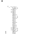
- FIG. 3 is a cross-sectional view of the image display device, which is a cross-sectional view taken along the line VV in FIG. 2;
- FIG. 4 is a cross-sectional view showing a state in which the visor hood is linearly expanded in the image display device;
- FIG. 4 is a cross-sectional view showing a state in which an object is in contact with the visor hood in the image display device;
- Cross-sectional view of a comparative example FIG.
- FIG. 4 is a cross-sectional view showing a state in which the visor hood is linearly expanded in the comparative example
- FIG. 10 is a cross-sectional view showing a state in which an object is in contact with the visor hood in the comparative example
- FIG. 2 is a longitudinal sectional view of the image display device; The figure which shows the structure around an image display apparatus in a vehicle interior.
- FIG. 13 is a cross-sectional view of the image display device, taken along line XIV-XIV of FIG. 12;
- FIG. 11 is a cross-sectional view of an image display device according to a third embodiment;
- FIG. 4 is a cross-sectional view showing a state in which the visor hood is linearly expanded in the image display device
- FIG. 11 is a cross-sectional view of an image display device according to Modification 1 of the third embodiment
- FIG. 4 is a cross-sectional view showing a state in which the visor hood is linearly expanded in the image display device
- FIG. 11 is a cross-sectional view of an image display device according to modification 2 of the third embodiment
- FIG. 4 is a cross-sectional view showing a state in which the visor hood is linearly expanded in the image display device
- the perspective view which shows the structure of a virtual-image display apparatus periphery in the vehicle interior in 4th Embodiment.
- FIG. 2 is a diagram showing the arrangement of display units in an image display device;
- FIG. 2 is a diagram showing the arrangement of displays in an image display device;
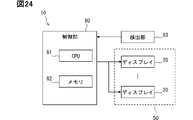
- FIG. 2 is a block diagram showing the electrical configuration of the image display device;
- FIG. 4 is a diagram for explaining an image displayed on a display surface;
- FIG. 4 is a diagram for explaining a virtual image displayed by a reflective surface;
- FIG. 5 is a diagram for explaining an image displayed on a display surface in a comparative example;
- FIG. 14 is a cross-sectional view of the periphery of the display overlapping portion in Modification 4 of the fifth embodiment
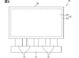
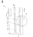
- An image display device 10 shown in FIG. 1 is mounted on a vehicle 100 .
- the image display device 10 is provided on an instrument panel 102 in a state of being exposed to the cabin 101 of the vehicle 100 .
- the instrument panel 102 is an instrument panel and is provided in front of a seat such as a driver's seat.
- the instrument panel 102 is an interior panel that forms the interior of the passenger compartment 101 .
- the interior panel forms a finished surface that is finished in the passenger compartment 101 .
- a steering wheel 105 is provided between the driver's seat and the instrument panel 102 .
- a front windshield 106 is located above the instrument panel 102 .
- the front of the seat is the front of vehicle 100 . Windshields of the vehicle 100 include the front windshield 106 as well as side windshields.
- the image display device 10 displays various information as an image V.
- the image display device 10 corresponds to a display device.
- Various information includes, for example, vehicle information and travel information.
- the vehicle information is information that indicates the amount of power stored in the vehicle-mounted battery
- the travel information is information that indicates the travel speed, travel mode, travel distance, and the like of the vehicle 100 .
- the various information includes navigation information, entertainment information, air conditioning information, camera information, and the like.
- the navigation information is information indicating the current value of the vehicle 100, information guiding a route from the current location to the destination, and the like.
- Camera information is information captured by an imaging device such as a camera.
- the camera information includes information obtained by imaging the surroundings of the vehicle 100 such as the rear of the vehicle 100 .
- the image display device 10 has a display surface 22 on which an image V can be displayed.
- the display surface 22 displays the image V by outputting image light.
- the image display device 10 has a hood rear surface 52 in addition to the display surface 22 .
- the image display device 10 is formed in a plate shape as a whole.
- the hood back surface 52 faces the side opposite to the display surface 22 in the device thickness direction.
- the device thickness direction is the thickness direction of the image display device 10, and is the direction extending vertically in the present embodiment.
- the device thickness direction is a direction orthogonal to the display surface 22 .
- the image display device 10 is included in the virtual image display device 11 together with the reflecting mirror 15 .
- the virtual image display device 11 is mounted on the vehicle 100 and displays the image V as a virtual image Vi.
- the reflecting mirror 15 is a reflecting member that reflects image light, and is sometimes called a reflecting mirror.
- the reflecting mirror 15 has a reflecting surface 16, and the reflecting surface 16 reflects the image light to display the virtual image Vi.
- Reflecting surface 16 is included in one of a pair of plate surfaces of reflecting mirror 15 .
- the reflecting mirror 15 is a member that performs reflection of the image light incident on the reflecting surface 16, out of transmission and reflection.
- the reflecting mirror 15 corresponds to a virtual image display section that displays a virtual image with image light.
- the reflecting mirror 15 is provided on the instrument panel 102 with the reflecting surface 16 exposed to the vehicle interior 101 .
- Reflecting mirror 15 is fixed to instrument panel 102 while being embedded in instrument panel 102 .
- the reflecting surface 16 faces obliquely upward so as to face the seat side. The reflective surface 16 is easily visible for the passenger sitting on the seat.
- the image display device 10 is provided so that the image light from the display surface 22 is reflected by the reflecting surface 16 toward the seat.
- the image display device 10 is provided above the reflecting mirror 15 with the display surface 22 facing downward and the hood rear surface 52 facing upward.
- the display surface 22 and the reflection surface 16 face each other. An occupant sitting on the seat looks as if the virtual image Vi displayed by the image light is behind the reflecting surface 16 .
- the occupant as a viewer does not directly see the display surface 22, but indirectly sees the display surface 22 by visually recognizing the reflection surface 16.
- the reflective surface 16 is the visible surface Sv visually recognized by the passenger. The occupant can visually recognize the virtual image Vi by visually recognizing the reflecting surface 16, which is the viewing surface Sv.
- the instrument panel 102 has a front portion 102a and a back portion 102b.
- the front portion 102a and the back portion 102b are arranged in the longitudinal direction of the vehicle.
- the vehicle front-rear direction is the front-rear direction for the vehicle 100 .
- the front portion 102 a forms the front end of the instrument panel 102 .
- the inner part 102b forms the inner end of the instrument panel 102.
- the back portion 102b is positioned higher than the front portion 102a.
- Reflecting mirror 15 is arranged between front portion 102a and back portion 102b. The reflecting mirror 15 is bridged between the front portion 102a and the back portion 102b so that the reflecting surface 16 faces obliquely upward.
- the image display device 10 protrudes forward from the back portion 102b.
- the image display device 10 is fixed to the back portion 102b and is cantilevered by the back portion 102b.
- the rear end of the image display device 10 is a base end fixed to the rear portion 102b.
- the front end portion of the image display device 10 is a tip portion arranged above the front portion 102a.
- the display surface 22 is inclined with respect to the reflective surface 16 .
- the separation distance between the display surface 22 and the reflection surface 16 increases toward a position closer to the front end of the image display device 10 .
- the display surface 22 extends in the horizontal direction or in a direction slightly inclined with respect to the horizontal direction.
- the image display device 10 is provided between the reflective surface 16 and the front windshield 106 and covers the reflective surface 16 from above.
- the hood back surface 52 faces the front windshield 106 .
- sunlight passes through the front windshield 106 and enters the vehicle compartment 101 , the sunlight easily strikes the hood back surface 52 but hardly strikes the reflecting surface 16 . Since sunlight does not hit the reflecting surface 16, which is the viewing surface Sv, the occupant can easily visually recognize the virtual image Vi on the viewing surface Sv.
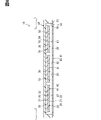
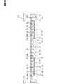
- the image display device 10 has a display 20, a heat insulating section 30, a heat radiating section 40, a visor hood 50, and a hood cover 60.
- the display 20, the heat insulation section 30, and the heat radiation section 40 are included in a display unit 70, which will be described later.
- the display 20 has a display surface 22 and a display back surface 24 .
- the display 20 is formed in a plate shape and has a pair of plate surfaces. In the display 20 , one plate surface is the display front surface 21 and the other plate surface is the display rear surface 24 .
- the display front surface 21 has a display surface 22 and a frame surface 23 (see FIG. 3).
- the display surface 22 has a horizontally long rectangular shape.
- the frame surface 23 has a rectangular frame shape and extends along the outer periphery of the display surface 22 .
- the display 20 can emit image light from the display surface 22 . No image light is emitted from the frame surface 23 .
- the display surface 22 is a display area where the image V is displayed, and the frame surface 23 is a non-display area where the image V is not displayed.
- the display 20 corresponds to an image display section, and the display rear surface 24 corresponds to a display rear surface. Display 20 may be referred to as a display.
- the reflecting mirror 15 displays the image V on the display surface 22 as a virtual image Vi, and displays the frame surface 23 as a virtual image V23 (not shown).
- the virtual image Vi of the image V is displayed by image light, while the virtual image V23 of the frame surface 23 is displayed simply by reflecting the frame surface 23 on the reflecting mirror 15 .
- the virtual image Vi that displays the image V is more conspicuous to the occupant than the virtual image V23 that reflects the frame surface 23 .
- the virtual image V23 is displayed so faintly that the occupant can hardly see it.
- the color of the frame surface 23 is a color that makes the virtual image V23 less noticeable.
- the color of the frame surface 23 is black.
- the color of the frame surface 23 may be the same color or a similar color as the color of the display surface 22 in the OFF state in which the display surface 22 does not display the image V.
- the color of the frame surface 23 may be lower than the color of the display surface 22 in the OFF state in at least one of saturation and brightness.
- the color of the frame surface 23 may be the same color as the background among the various information and the background included in the image V, or a similar color.
- the display 20 is a self-luminous display unit.
- the display 20 includes, for example, an organic EL display.
- An organic EL display includes organic light emitting diodes.
- An organic light-emitting diode is sometimes called an OLED, which is an abbreviation for Organic Light-Emitting Diode.
- the display 20 has a plurality of display elements such as organic EL elements. The plurality of display elements are arranged in a matrix along the display surface 22, and each emits light that becomes image light.
- the display 20 is self-luminous, it does not require a backlight as a light source. In the display 20 configured without a backlight in this way, it is possible to display the black portion of the image V by stopping the light emission of the light emitting elements. On the other hand, unlike this embodiment, in a display with a backlight that includes a backlight, it is conceivable that the light of the backlight slightly leaks from the black portion of the image V. FIG. If even a small amount of light from the backlight leaks from a black portion in the image V, the black portion or its surroundings will appear whitish.
- the visor hood 50 accommodates the display 20 , the heat insulating section 30 and the heat radiating section 40 in a state in which the image light on the display surface 22 can be directed toward the reflecting mirror 15 .
- the visor hood 50 is made of a resin material or the like and has a light shielding property.
- the visor hood 50 is formed in a plate shape as a whole.
- the thickness direction of the visor hood 50 is the device thickness direction.
- a visor hood 50 covers the display back surface 24 of the display 20 .
- the visor hood 50 corresponds to a display case and is sometimes called a housing case or a meter hood.
- the visor hood 50 has a hood front surface 51 in addition to a hood rear surface 52 .
- the visor hood 50 is formed in a plate shape as a whole and has a pair of plate surfaces.
- one plate surface is the hood rear surface 52 and the other plate surface is the hood front surface 51 .
- the hood back surface 52 corresponds to the back surface of the display case.
- the visor hood 50 has a hood concave portion 53 provided on the hood front surface 51 .
- the hood recess 53 is a recess that is recessed toward the hood rear surface 52 in the hood front surface 51 .
- the hood recessed portion 53 is open toward the side opposite to the hood rear surface 52 .
- the hood concave portion 53 is provided at a position spaced inward from the outer peripheral edge of the hood front surface 51 .
- the hood front surface 51 extends along the outer peripheral edge of the hood concave portion 53 and has a frame shape.
- the hood recess 53 forms a recessed opening 56 in the hood front surface 51 .
- the recessed opening 56 is an opening formed by the open end of the hood recessed portion 53 .
- the inner surface of the hood concave portion 53 includes a concave bottom surface 54 and a concave wall surface 55 .
- the concave bottom surface 54 is the bottom surface of the hood concave portion 53 and faces the side opposite to the hood rear surface 52 in the device thickness direction.
- a concave bottom surface 54 extends along the hood back surface 52 .
- the concave wall surface 55 extends along the outer peripheral edge of the concave opening 56 .
- the concave wall surface 55 spans the outer peripheral edge of the concave bottom surface 54 and the inner peripheral edge of the hood front surface 51 in the device thickness direction.
- the display 20 is housed in the hood concave portion 53 with the display surface 22 facing away from the concave bottom surface 54 .
- the concave bottom surface 54 faces the display back surface 24 and corresponds to the case facing surface.
- a concave bottom surface 54 extends along the display back surface 24 .
- the visor hood 50 covers the display 20 from the display back surface 24 side.
- the visor hood 50 is located between the display 20 and the front windshield 106 and functions as a light blocking plate. Sunlight traveling toward the display 20 through the front windshield 106 is blocked by the visor hood 50 . Therefore, the visor hood 50 prevents the display 20 from receiving direct sunlight.
- the visor hood 50 has a hood distal end portion 57 and a hood proximal end portion 58 .
- the hood distal end portion 57 forms the distal end portion of the image display device 10
- the hood proximal end portion 58 forms the proximal end portion of the image display device 10 .
- the visor hood 50 is fixed to the back portion 102b and protrudes forward from the back portion 102b in an eave shape.
- the visor hood 50 is a member attached to the instrument panel 102 and attached to the instrument panel 102 in the vehicle interior 101 .
- the visor hood 50 is in a state of being cantilevered by the back portion 102b, and is sometimes called an eaves member.
- the visor hood 50 forms the interior of the passenger compartment 101 .
- the hood cover 60 is fixed to the visor hood 50 while covering the concave opening 56 .
- the hood cover 60 has translucency, and is made of, for example, a resin material or a glass material.
- the hood cover 60 is formed in a plate shape and has a pair of plate surfaces.
- One plate surface of the hood cover 60 is a cover front surface 61 and the other plate surface is a cover rear surface 62 .
- Both the cover front surface 61 and the cover back surface 62 extend along the display surface 22 .
- the cover front surface 61 faces away from the display surface 22 .
- the cover back surface 62 faces the display surface 22 side and faces the display surface 22 .
- the hood cover 60 is arranged at a position spaced forward from the display surface 22 .
- the image light emitted from the display surface 22 passes through the hood cover 60 and is irradiated onto the reflecting mirror 15 .
- the radiator 40 radiates the heat of the display 20 to the outside of the visor hood 50 .
- the heat radiating section 40 has a heat radiating plate section 41 and heat radiating fins 44 . Both the radiator plate portion 41 and the radiator fins 44 are made of a metal material or the like, and have thermal conductivity.
- the radiator plate portion 41 extends along the display back surface 24 and is provided between the display back surface 24 and the heat insulation portion 30 .
- the radiator plate portion 41 is a heat transfer material and forms a heat transfer layer.
- the heat dissipation plate portion 41 has a heat dissipation front face 42 and a heat dissipation back face 43 .
- the radiator plate portion 41 is formed in a plate shape and has a pair of plate surfaces. In the radiator plate portion 41 , one plate surface is a heat radiation front surface 42 and the other plate surface is a heat radiation rear surface 43 .
- the heat dissipating front surface 42 overlaps the display back surface 24 , and the heat dissipating back surface 43 faces the concave bottom surface 54 .
- the heat dissipation plate portion 41 and the display 20 are fixed to each other by joining the heat dissipation front face 42 and the display back face 24 with an adhesive or the like.
- the heat radiation fins 44 are thermally connected to the heat radiation plate portion 41 .
- the radiation fins 44 extend from the radiation plate portion 41 toward the outside of the visor hood 50 and correspond to radiation extension portions.
- the radiating fins 44 have a plurality of fin portions and connecting portions that connect these fin portions.
- the radiation fins 44 are exposed outside the visor hood 50 .
- the heat radiation fins 44 extend from the heat radiation plate portion 41 toward the hood front surface 51 in the device thickness direction.
- the radiation fin 44 is provided at a position spaced apart from the hood concave portion 53 toward the hood base end portion 58 side.
- the radiating fins 44 are positioned apart from the display 20 on both the hood base end portion 58 side and the hood rear surface 52 side.
- the radiation fins 44 are covered from above by at least one of the visor hood 50 and the instrument panel 102 .
- at least one of the visor hood 50 and the instrument panel 102 blocks the irradiation of sunlight to the radiation fins 44 .
- the heat radiation fins 44 are detachably connected to the heat radiation plate portion 41 .
- the radiation fins 44 are fixed to the radiation plate portion 41 by fasteners such as screws.
- the connecting portion of the heat radiating fin 44 and the heat radiating plate portion 41 are connected inside the hood recess 53 .
- the heat radiating plate portion 41, the heat radiating fins 44 and the connector form a heat transfer path.
- the heat transfer path of the heat dissipation portion 40 is a heat dissipation path that releases the heat of the display 20 to the outside of the visor hood 50 .
- the heat insulation part 30 restricts the heat of the visor hood 50 from being transmitted from the concave bottom surface 54 to the display 20 .
- the heat insulating portion 30 is sometimes called a heat transfer restricting portion.
- the heat applied to the visor hood 50 is solar heat.
- solar heat is a type of external light that passes through the windshield and irradiates the hood back surface 52 .
- Sunlight is a type of external light that passes through the windshield and irradiates the hood back surface 52 .
- sunlight is a kind of outside light heat.
- the image display device 10 there are two separate heat paths.
- One of the two heat paths is a heat insulation path through which the heat insulation section 30 blocks solar heat, and the other is a release path through which the heat dissipation section 40 releases heat from the display 20 .
- the heat insulation path is on the hood rear surface 52 side, and the heat radiation path is on the hood front surface 51 side.
- the heat-insulating path and the heat-radiating path are on opposite sides of each other in the device thickness direction.
- the heat insulating part 30 is a heat insulating material made of a resin material, a fiber material, or the like, and has heat insulating properties.
- the thermal conductivity of the heat insulating portion 30 is approximately the same as or lower than the thermal conductivity of air, for example.
- As the heat insulating material there are a combination of resin foam or non-woven fabric and a high-performance heat insulating member such as silica airgel, and a flexible vacuum heat insulating member.
- the heat insulation part 30 forms a heat insulation layer.
- the heat insulating property of the heat insulating portion 30 is higher than that of the visor hood 50 .
- the thermal conductivity of the heat insulating portion 30 is difficult to change even if the temperature of the heat insulating portion 30 changes.
- the thermal conductivity of air tends to change as the temperature of the air changes. For this reason, for example, unlike the present embodiment, in the configuration in which the heat insulating layer is formed with air, there is concern that the heat insulating performance of the heat insulating layer may change with changes in the temperature of the heat insulating layer.
- the heat insulation part 30 is an elastic member having elasticity and stretchability, and is elastically deformable.
- the heat insulating portion 30 elastically deforms or flexibly expands and contracts when an external force is applied to the heat insulating portion 30 .
- the heat insulating portion 30 expands and contracts according to the temperature change of the heat insulating portion 30 .
- the heat insulating portion 30 expands as the temperature rises and shrinks as the temperature drops.
- the heat insulating portion 30 may change its flexibility according to the temperature change of the heat insulating portion 30 .
- the heat insulating portion 30 may become more flexible as the temperature rises and less flexible as the temperature drops.
- the heat insulating portion 30 is more likely to linearly expand or deform due to an external force than the visor hood 50 and the radiator plate portion 41 . That is, the heat insulating portion 30 has a larger coefficient of linear expansion or a lower tensile strength and Young's modulus than the visor hood 50 and the radiator plate portion 41 .
- the heat insulating portion 30 extends along the concave bottom surface 54 and is provided between the concave bottom surface 54 and the radiator plate portion 41 .
- the heat insulating portion 30 is formed in a plate shape and has a pair of plate surfaces.
- one plate surface is the heat insulating front surface 31 and the other plate surface is the heat insulating rear surface 32 .
- the heat-insulating front surface 31 is superimposed on the heat-dissipating back surface 43 and is joined to the heat-dissipating back surface 43 with an adhesive or the like.
- the adiabatic front surface 31 faces the display back surface 24 .
- the heat insulating back surface 32 is overlaid on the concave bottom surface 54 and joined to the concave bottom surface 54 by an adhesive or the like.
- the heat insulating portion 30 is fixed to both the radiator plate portion 41 and the visor hood 50 .
- the display 20 is fixed to the concave bottom surface 54 via the radiator plate portion 41 and the heat insulating portion 30 .
- the elastically deformable heat insulating portion 30 is elastically deformed according to the relative displacement of the display 20 and the radiator plate portion 41 with respect to the visor hood 50 .
- the elastic deformation of the heat insulating portion 30 suppresses the relative displacement of the heat radiating plate portion 41 with respect to the visor hood 50 and the increase in the vibration of the heat radiating plate portion 41 and the display 20 .
- the relative displacement of the display 20 and the heat sink portion 41 with respect to the visor hood 50 includes deformation of at least one of the visor hood 50 , the display 20 and the heat sink portion 41 .
- the vibration of the display 20 is also suppressed by vibration damping and back support by preload.
- vibration damping and back support by preload unlike the present embodiment, in a configuration in which there is an air layer instead of the heat insulating portion 30 on the back side of the display 20, there is a concern that the display 20 may easily vibrate without obtaining an additional effect of suppressing vibration. .
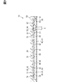
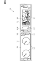
- the display 20 is included in a display unit 70, as shown in FIG.
- a display unit 70 is included in the image display device 10 .
- the display unit 70 has a circuit board 71 and a connection cable 72 in addition to the display 20 .
- the circuit board 71 controls the display 20 by controlling light-emitting elements and the like.
- the circuit board 71 is mounted with electronic components and constitutes, for example, a driver circuit.
- the connection cable 72 electrically connects the circuit board 71 and the display 20 and inputs signals from the circuit board 71 to the display 20 .
- the connection cable 72 is a flexible strip-shaped cable, such as a flexible flat cable.
- a plurality of connection cables 72 are arranged along the outer surface of the display 20 .
- the display unit 70 is housed in the visor hood 50. That is, the visor hood 50 accommodates the circuit board 71 and the connection cable 72 in addition to the display 20 .
- the circuit board 71 is provided at a position spaced apart from the display 20 toward the hood base end portion 58 side.
- at least one of the visor hood 50 and the instrument panel 102 blocks the irradiation of sunlight to the circuit board 71 and the connection cable 72 . Note that the circuit board 71 and the connection cable 72 do not have to be accommodated in the visor hood 50 as long as the circuit board 71 and the connection cable 72 are blocked from being irradiated with sunlight.
- a pair of A-pillars 108 are arranged in the vehicle width direction.
- the A-pillar 108 is provided side by side with the front windshield 106 in the vehicle width direction.
- the A pillar 108 corresponds to a pillar and is sometimes called a front pillar.
- the front windshield 106 is in a state of being stretched over a pair of A-pillars 108 in the vehicle width direction.
- the vehicle width direction is the width direction of the vehicle 100 and is a direction perpendicular to the vehicle front-rear direction.
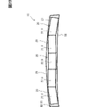
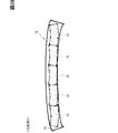
- the virtual image display device 11 extends in the vehicle width direction.
- the virtual image display device 11 is installed in the vehicle 100 so that the device width direction is the vehicle width direction.
- the device width direction is the width direction of the image display device 10 .
- both the image display device 10 and the reflecting mirror 15 extend in the vehicle width direction.
- the image display device 10 and the reflecting mirror 15 extend in the vehicle width direction at least in front of the driver's seat.
- the visor hood 50 and the hood cover 60 extend in the vehicle width direction.
- the visor hood 50, the hood cover 60, and the reflecting mirror 15 are all in a state of extending over both side ends of the instrument panel 102 in the vehicle width direction.
- a plurality of display units 70 are arranged in the vehicle width direction.
- a plurality of displays 20 and circuit boards 71 are arranged along the concave bottom surface 54 in the vehicle width direction.
- a plurality of display surfaces 22 are arranged in the vehicle width direction.
- the virtual images Vi displayed by the respective display surfaces 22 are arranged side by side in the vehicle width direction on the reflecting mirror 15 .
- the plurality of virtual images Vi are arranged side by side so as to extend over both side ends of the instrument panel 102 in the vehicle width direction.
- the display unit 70 includes a heat insulating section 30 and a heat radiating section 40 .
- the ends of the display 20, the heat insulating portion 30, and the heat sink portion 41 in the vehicle width direction are arranged in the device thickness direction.
- a plurality of the display 20 , the heat insulation portion 30 and the heat radiation plate portion 41 are arranged along the concave bottom surface 54 in the width direction of the vehicle.
- a plurality of display units 70 are individually fixed to the concave bottom surface 54 . Therefore, each of the plurality of display units 70 can be individually attached to and detached from the visor hood 50 .
- a plurality of display front surfaces 21 are arranged in the width direction of the device.
- the plurality of display front surfaces 21 all face the reflective surface 16 .
- the respective display surfaces 22 and frame surfaces 23 both face the reflective surface 16 .
- the respective frame surfaces 23 have the same color or a similar color. All the colors of these frame surfaces 23 are black, for example, and have the same saturation and brightness. At least one of hue, saturation, and lightness may differ between the plurality of frame surfaces 23, but the smaller the difference, the better.
- a plurality of display surfaces 22 and a plurality of frame surfaces 23 are provided, while a reflecting surface 16 and a cover front surface 61 are provided one each.
- a plurality of virtual images Vi generated from a plurality of images V are collectively displayed on one reflecting surface 16 .
- the virtual image Vi that reflects the image V is more conspicuous than the virtual image V23 that reflects the frame surface 23. FIG. For this reason, it is easier for the passenger to visually recognize the plurality of virtual images Vi in an integrated state rather than in a state of being partitioned by the frame surface 23 .
- the multiple displays 20 are provided at positions that do not block the image light emitted from each. Among the two displays 20 adjacent to each other, one display 20 is provided at a position that does not block the image light emitted from the other display 20 .
- the respective thickness dimensions of the respective displays 20, heat insulating portions 30, and heat radiating plate portions 41 are uniform and substantially the same.
- the respective display surfaces 22, heat-insulating front surfaces 31, and heat-radiating front surfaces 42 are all arranged side by side in the vehicle width direction.
- the distances between the respective display surfaces 22 and the reflecting mirrors 15 are uniform and substantially the same.
- the two adjacent display units 70 are separated from each other.
- the respective displays 20, heat insulating portions 30, and radiator plate portions 41 are separated from each other.
- the gap between the displays 20, the gap between the heat insulating portions 30, and the gap between the heat sink portions 41 are arranged in the device thickness direction.
- Each of the display 20, the heat insulating portion 30, and the heat sink portion 41 has a pair of side end portions aligned in the device width direction.
- the side edges of the display 20, the heat insulating portion 30, and the heat sink portion 41 are arranged in the device thickness direction.
- the heat insulation section 30 is provided between the display back surface 24 and the concave bottom surface 54 .
- the heat insulating portion 30 can prevent the solar heat as outside light heat from being transmitted from the visor hood 50 to the display 20 . Therefore, the heat insulating portion 30 can prevent the temperature of the display 20 from excessively rising due to solar heat and causing an abnormality in the display 20 .
- the instrument panel 102 and the visor hood 50 there is concern that the temperature of 50 will be excessively high.
- the temperature of the instrument panel 102 and the visor hood 50 may exceed 100°C. If the temperature of the visor hood 50 becomes excessively high in this manner, the display 20 and the circuit board 71 inside the visor hood 50 may be thermally deteriorated or damaged. In particular, when the temperature of the organic EL display exceeds 90.degree. C. and rises to nearly 100.degree.
- a method of air-cooling the visor hood 50 with an electric fan or the like can be considered.
- a method of providing an air layer of about 5 to 15 mm between the visor hood 50 and the display 20 can be considered. This method makes it difficult for the heat of the sun to be transmitted directly from the visor hood 50 to the display 20 .
- the thickness of the visor hood 50 is increased by the amount of the air layer, and it is conceivable that the clean appearance design of the image display device 10 is impaired.
- the heat insulation portion 30 mitigates the solar heat transmitted from the concave bottom surface 54 to the display back surface 24 . Therefore, even when the power switch of vehicle 100 is turned off, it is possible to prevent the temperature of display 20 from becoming excessively high. Further, by making the heat insulating portion 30 thinner than the air layer, the visor hood 50 becomes thinner, and the thickness of the image display device 10 can be reduced. Therefore, in response to the growing need for thin designs for laptop computers, smartphones, vehicle-mounted displays, and the like, it is possible to independently arrange a thin image display device 10 having a thickness of, for example, 10 to 20 mm.
- the visor hood 50 is attached to the instrument panel 102 when the image display device 10 is mounted on the vehicle 100 .
- the temperature of visor hood 50 tends to become excessively high when sunlight transmitted through the windshield is applied to visor hood 50.
- FIG. Therefore, the configuration in which heat from the visor hood 50 is restricted from being transmitted to the display 20 by the heat insulating portion 30 is effective for the image display device 10 mounted on the vehicle 100 from the viewpoint of protecting the display 20 from heat.
- the heat insulating portion 30 is elastically deformed according to the relative displacement of the display 20 with respect to the visor hood 50 , and the display 20 is fixed to the concave bottom surface 54 via the heat insulating portion 30 .
- the transmission of this vibration from the visor hood 50 to the display 20 can be suppressed by the elastic deformation of the heat insulating portion 30 .
- the transmission of vibration from the visor hood 50 to the display 20 can be suppressed by elastic deformation of the heat insulating portion 30, damping of vibration, and back support by preload.
- the elastic deformation of the heat insulating portion 30 can prevent the display 20 from becoming abnormal due to the vibration of the visor hood 50 . Moreover, the elastic deformation of the heat insulating portion 30 can suppress the display 20 from vibrating due to the vibration of the vehicle 100 .
- a plurality of heat insulating portions 30 are arranged along the concave bottom surface 54 .
- each of the plurality of heat insulating portions 30 deforms individually. Therefore, even if the concave bottom surface 54 expands in the width direction due to the linear expansion of the visor hood 50 , the expansion of the concave bottom surface 54 is individually absorbed by the plurality of heat insulating portions 30 . Therefore, the plurality of heat insulating portions 30 can suppress the stress generated by the linear expansion of the visor hood 50 from being applied to the display 20 .
- the visor hood 50 may be deformed when an external force is applied to the visor hood 50 by an occupant or the like, or when the vehicle 100 travels and shakes significantly. Conceivable.
- each of the multiple displays 20 is individually provided with the heat insulation section 30 .
- the heat insulating portions 30 provided for each of the multiple displays 20 deform individually. Therefore, the elongation of the concave bottom surface 54 is individually absorbed by the heat insulating portion 30 for each display 20 . Therefore, it is possible to individually suppress the occurrence of deformation such as bending of the display 20 for each of the plurality of displays 20 .
- the stress and load caused by the linear expansion of the visor hood 50 can be distributed to the multiple displays 20 via the multiple heat insulating portions 30 . Furthermore, it is possible to suppress the peeling of the bond between the heat sink portion 41 and the heat insulating portion 30 and the peeling of the bond between the display 20 and the heat sink portion 41 .
- the heat insulating portions 30 individually provided for each display 20 are separated from each other.
- the heat insulating portions 30 provided for each two adjacent displays 20 come into contact with each other, and these heat insulating portions 30 cannot be deformed to extend. can be suppressed. Therefore, it is possible to more reliably suppress the occurrence of abnormalities such as deformation of the display 20 due to the linear expansion of the visor hood 50 .
- the heat radiation fins 44 are positioned apart from the display 20 . With this configuration, it is possible to prevent the heat transferred from the display 20 to the heat dissipation fins 44 through the heat dissipation plate portion 41 from returning to the display 20 again. Therefore, heat radiation from the display 20 can be reliably performed by the radiation fins 44 and the radiation plate portion 41 .
- the radiator plate portion 41 is individually provided for each of the plurality of heat insulating portions 30 .
- the heat radiating plate portion 41 is individually displaced or deformed for each heat insulating portion 30 . Therefore, it is possible to prevent the joint between the heat insulating portion 30 and the heat sink portion 41 from coming off.
- both the heat insulation section 30 and the heat radiation plate section 41 are individually provided for each of the plurality of displays 20 .
- the radiator plate portion 41 is deformed or displaced for each display 20 in accordance with the deformation of the heat insulating portion 30. . Therefore, it is possible to suppress peeling of the joint between the heat insulating part 30 and the radiator plate part 41 and peeling of the joint between the radiator plate part 41 and the display 20 .
- the radiator plate portions 41 provided for each display 20 are separated from each other.
- the heat radiating plate portions 41 provided for the adjacent displays 20 come into contact with each other, and the heat radiating plate portions 41 are heat insulated. Inhibition of deformation of the portion 30 can be suppressed. Therefore, it is possible to more reliably suppress the occurrence of an abnormality such as deformation of the display 20 due to the inability of the heat insulating portion 30 to absorb the linear expansion of the visor hood 50 .
- each of the heat insulation portion 30 and the heat radiation plate portion 41 is provided so as to extend over the plurality of displays 20 .
- the heat insulation portion 30 and the heat radiation plate portion 41 provided for the plurality of displays 20 are both integrally formed into one continuous body.
- this stress is applied to the joint portion between the visor hood 50 and the heat insulating portion 30, the joint portion between the heat sink portion 41 and the heat insulating portion 30, and the joint portion between the display 20 and the heat sink portion 41. There is concern that peeling may occur.
- a plurality of displays 20 and a plurality of heat sink portions 41 are arranged along the concave bottom surface 54 .
- the radiator plate portion 41 corresponding to this display 20 can be attached and detached. In this way, the display 20 and the radiator plate portion 41 can be attached and detached individually, so that the workload and cost can be reduced.
- the display 20 when the display 20 is attached and detached, the display 20 may be replaced.
- the display 20 may be replaced.
- the display 20 may be replaced.
- an object X touches the display 20 as shown in FIG. A worker first removes the hood cover 60 from the visor hood 50 when attaching, detaching, or replacing the display 20 or the like. Then, the display 20 or the like is attached, detached or replaced through the recessed opening 56 .
- the radiator plate portion 41 is individually provided for each display 20 , it is possible to easily attach and detach the radiator plate portion 41 together with the display 20 .
- the display 20 and the radiator plate portion 41 can be attached and detached together instead of sequentially attaching and detaching the display 20 and the radiator plate portion 41 with respect to the visor hood 50 . Therefore, it is possible to reduce the work load when attaching and detaching the display 20 and the heat sink portion 41 .
- radiator plate portions 41 provided for each display 20 are separated from each other. Therefore, when an operator attaches and detaches one heat sink portion 41, the adjacent heat sink portion 41 is less likely to interfere. For example, it is possible to facilitate the work of inserting a hand or a tool into the gap between two adjacent heat sink portions 41 to remove one of the heat sink portions 41 . Therefore, it is possible to improve work efficiency when attaching and detaching the display 20 and the heat sink portion 41 .
- a plurality of displays 20 and a plurality of heat insulating portions 30 are arranged along the concave bottom surface 54 .
- this configuration for example, when replacing one display 20, only the heat insulating portion 30 corresponding to this display 20 can be replaced. In this way, the display 20 and the heat insulation part 30 can be individually replaced, so that the work burden and cost can be reduced.
- the heat insulation part 30 is provided for each display 20 individually, it is possible to easily attach and detach the heat insulation part 30 together with the display 20 .
- the display 20 and the heat insulating section 30 can be attached and detached collectively. Therefore, it is possible to reduce the work load when attaching and detaching the display 20 and the heat insulation part 30 .
- the heat insulating portions 30 individually provided for each display 20 are separated from each other. Therefore, when an operator attaches and detaches one heat insulating portion 30, the adjacent heat insulating portion 30 is less likely to interfere. For example, it is possible to facilitate the work of inserting a hand or a tool into a gap between two adjacent heat insulating portions 30 to remove one of the heat insulating portions 30 . Therefore, it is possible to improve the working efficiency when attaching and detaching the display 20 and the heat insulation part 30 .
- two adjacent displays 20 are separated from each other. Therefore, when an operator attaches or detaches one display 20, the adjacent display 20 is less likely to interfere. For example, it is possible to facilitate the work of inserting a hand or a tool into the gap between two adjacent displays 20 to remove one of the displays 20 . Therefore, it is possible to improve work efficiency when attaching and detaching the display 20 .
- the present embodiment it is possible to attach and detach part of the heat radiating plate portion 41 and the heat insulating portion 30 as described above, so that the work load can be reduced. Moreover, it is not necessary to replace all the radiator plate portions 41 and heat insulating portions 30 housed in the visor hood 50 . Therefore, the material cost of the radiator plate portion 41 and the heat insulating portion 30 can be reduced.
- the display 20 is fixed to the heat insulation section 30 via the radiator plate section 41 .
- the elastic deformation of the heat insulating portion 30 can suppress the transmission of the vibration from the visor hood 50 to the radiator plate portion 41 . Therefore, even if the display 20 is configured to dissipate heat through the heat-dissipating plate portion 41 , the display 20 and the heat-dissipating plate portion 41 may become abnormal due to the vibration of the visor hood 50 . can be suppressed by
- the heat radiation fins 44 extend from the heat radiation plate portion 41 toward the outside of the visor hood 50 .
- the heat transmitted from the display 20 to the radiator plate portion 41 is easily released from the radiator fins 44 to the outside of the visor hood 50 . Therefore, it is possible to prevent the heat of the display 20 from staying inside the visor hood 50 and further increasing the temperature of the display 20 due to the heat that is staying.
- a plurality of heat sink portions 41 are arranged along the concave bottom surface 54 .
- the heat is less likely to be transferred to the other radiator plate portions 41 . Therefore, by dividing the heat sink portion 41 into a plurality of portions, it is possible to suppress the spread of heat from a portion of the image display device 10 over a wide area. For example, when some displays 20 generate excessive heat, it is possible to suppress the occurrence of abnormalities in the other displays 20 to which the heat is transferred via the radiator plate portion 41 .
- the plurality of display surfaces 22 are arranged along the reflecting surface 16 while facing the reflecting surface 16 .
- the image V displayed on each of the multiple display surfaces 22 is displayed as multiple virtual images Vi by the reflecting surface 16 . Therefore, it is possible for the passenger to collectively view the plurality of virtual images Vi on the single reflecting surface 16 . Since the reflecting surface 16 is the viewing surface Sv for the passenger, the viewing surface Sv can be enlarged in the virtual image display device 11 .
- the virtual image Vi displayed by the image light is more conspicuous than the virtual image V23 in which only the frame surface 23 is reflected. Therefore, it is possible to reduce the conspicuousness of the virtual image gap area on one viewing surface Sv that displays a plurality of virtual images Vi.
- the virtual image gap area is an area indicating the gap between adjacent virtual images Vi. Therefore, it is possible to prevent the occupant from having a sense of discomfort in the virtual image gap area when the occupant visually recognizes the viewing surface Sv. In other words, it is possible to enhance the seamlessness of the plurality of virtual images Vi viewed from the viewing surface Sv.
- a self-luminous display unit is used as the display 20
- leakage of backlight from black portions of the image V can be avoided.
- the display front surface 21 leakage of backlight from the boundary between the outer peripheral edge of the display surface 22 and the inner peripheral edge of the frame surface 23 is avoided. Therefore, it is possible to prevent the frame surface 23 from being conspicuous due to the light of the backlight in the virtual image gap area. Therefore, the seamless feeling on the viewing surface Sv can also be enhanced by preventing light leakage from the backlight.
- a plurality of displays 20 are arranged in the device width direction. With this configuration, it is possible to prevent image light emitted from one of the two displays 20 adjacent to each other from being blocked by the other display 20 . Therefore, it is possible to prevent the virtual image gap area from being conspicuous due to the blocking of the image light.
- the frame surfaces 23 of the multiple displays 20 have the same color.
- the virtual image V23 of the frame surface 23 can be made uniform in the degree to which the virtual image V23 of the frame surface 23 is inconspicuous for the plurality of displays 20 . Therefore, when a plurality of virtual images V23 are displayed on the viewing surface Sv of the frame surface 23, it is possible to prevent only some of the virtual images V23 from standing out.
- the visor hood 50 that covers the display back surface 24 is in a state of spanning over the multiple displays 20 . Therefore, the visor hood 50 can prevent the plurality of displays 20 from being displaced. For example, the visor hood 50 can prevent the two adjacent display surfaces 22 from being relatively displaced and the two virtual images Vi displayed by these display surfaces 22 to be displaced.
- the visor hood 50 spans over the pair of A-pillars 108.
- the portion where the visor hood 50 is fixed to the instrument panel 102 can be arranged at a position as close to the A-pillar 108 as possible. Therefore, the support strength of the visor hood 50 by the instrument panel 102 can be increased.
- the visor hood 50 can be made as large as possible in the vehicle width direction in the vehicle compartment 101 . Therefore, the number of image display devices 10 accommodated in the visor hood 50 can be increased.
- the viewing surface Sv which is the reflecting surface 16, can be increased in size.
- the visor hood 50 is a member attached to the instrument panel 102 . Therefore, it is possible to prevent the visor hood 50 from degrading the design of the passenger compartment 101 . Therefore, the visor hood 50 can enhance the design of the passenger compartment 101 . In particular, in a configuration in which the visor hood 50 is also enlarged in accordance with an increase in the size of the visible surface Sv, the visor hood 50 tends to stand out in the vehicle interior 101 . Therefore, it is effective to improve the design of the passenger compartment 101 by using the visor hood 50 .
- the reflecting surface 16 is arranged so as to be visually recognized by the viewer as the viewing surface Sv.
- the cover front surface 61 is arranged so as to be visually recognized by the viewer as the viewing surface Sv. Configurations, actions, and effects not specifically described in the second embodiment are the same as those in the first embodiment. 2nd Embodiment demonstrates centering on a different point from the said 1st Embodiment.
- the occupant can view the image V instead of the virtual image Vi on the viewing surface Sv.
- the vehicle 100 is not equipped with the reflecting mirror 15 , and the image display device 10 does not constitute the virtual image display device 11 .
- the image display device 10 shown in FIGS. 11 to 14 is installed so that the cover front surface 61 is visible.
- the cover front surface 61 faces obliquely upward so as to face the seat side. It is easy for an occupant sitting on the seat to visually recognize the front surface 61 of the cover.
- the front surface 61 of the cover is the visible surface Sv that is visually recognized by the occupant.
- the occupant can visually recognize the image V by visually recognizing the cover front surface 61, which is the viewing surface Sv.
- Image light emitted from the display surface 22 passes through the hood cover 60 and travels toward the seat.
- the occupant does not look at the display surface 22 indirectly as in the first embodiment, but directly looks at the display surface 22 through the hood cover 60 . 13, illustration of the hood front surface 51 is omitted.
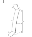
- the device thickness direction is the direction extending in the front-rear direction of the vehicle 100 .
- the image display device 10 is provided on the instrument panel 102 with the cover front surface 61 and the hood rear surface 52 exposed to the vehicle interior 101 .
- the image display device 10 extends upward from the instrument panel 102 .
- the image display device 10 is inserted between the front portion 102a and the back portion 102b.
- a lower end portion of the image display device 10 is a base end portion that is recessed into the instrument panel 102 and fixed to the instrument panel 102 .
- An upper end portion of the image display device 10 is a tip portion disposed above the inner portion 102b.
- the cover front surface 61 extends in the vertical direction or in a direction slightly inclined with respect to the vertical direction.
- the image display device 10 is provided below the front windshield 106 .
- the display surface 22 and the cover front surface 61 face in a different direction than the front windshield 106 .
- the sunlight easily strikes the hood rear surface 52 but hardly strikes the display surface 22 and the cover front surface 61 .
- the hood front end portion 57 forms the upper end portion of the image display device 10 and the hood base end portion 58 forms the lower end portion of the image display device 10 .
- the visor hood 50 is fixed to the instrument panel 102 with the hood base end portion 58 disposed below the front portion 102a and the back portion 102b.
- the heat radiating fins 44 are covered with the instrument panel 102 from above.
- the radiation fins 44 are arranged below the deep portion 102b and are covered with the deep portion 102b from above.
- the instrument panel 102 blocks sunlight from radiating to the radiation fins 44 . It should be noted that the position of the radiation fins 44 does not have to be the position spaced apart from the hood concave portion 53 toward the hood base end portion 58 side.
- the main difference between the present embodiment and the first embodiment is that the orientations of the display surface 22 and the cover front surface 61 are different. Therefore, the image display device 10 of the present embodiment can achieve the effects of the image display device 10 of the first embodiment.
- the effects described in ⁇ Configuration group A> of the first embodiment are effects that the image display device 10 of the present embodiment can also exhibit.
- ⁇ Third Embodiment> In the first embodiment, two adjacent displays 20 are arranged in the device width direction. In contrast, in the third embodiment, two adjacent displays 20 partially overlap each other in the device thickness direction. 3rd Embodiment demonstrates the structure which applied the duplication structure in which the two displays 20 overlapped in this way to the said 1st Embodiment. This overlapping configuration may be applied to the second embodiment. Configurations, actions, and effects that are not specifically described in the third embodiment are the same as those in the first embodiment. 3rd Embodiment demonstrates centering on a different point from the said 1st Embodiment.
- one of the two adjacent displays 20 is arranged closer to the viewer than the other.
- the display 20 arranged on the front side is called a front display 20A
- the display 20 arranged on the back side is called a back display 20B.
- Both the front display 20A and the rear display 20B extend parallel to the concave bottom surface 54 and the cover front surface 61 .
- the multiple displays 20 include two rear displays 20B adjacent to each other with a front display 20A interposed therebetween.
- One side end portion 25 of the front display 20A is on the front side of one of the two rear displays 20B, the rear display 20B.
- the other side end portion 25 is on the front side of the other of the two rear displays 20B.
- a side end portion 25 of the front display 20A is arranged at a position overlapping the rear display 20B in the device thickness direction.
- a side end portion 25 of the front display 20A is arranged on the front side of the display front surface 21 of the rear display 20B.
- the front display 20A is arranged at a position that does not block the image light emitted from the rear display 20B.
- the side end portion 25 of the front display 20A is arranged at a position that overlaps the frame surface 23 of the rear display 20B, but is arranged at a position that does not overlap the display surface 22 of the rear display 20B.
- the plurality of display units 70 includes a front display unit 70A and a rear display unit 70B.
- the front display unit 70A has a front display 20A
- the rear display unit 70B has a rear display 20B.
- the visor hood 50 has a bottom projection 54a.
- the bottom protrusion 54 a is a protrusion formed by protruding a portion of the concave bottom surface 54 toward the concave opening 56 .
- the portion having the bottom convex portion 54a among the portions forming the concave bottom surface 54 is partially thick.
- the tip surface of the bottom convex portion 54 a is included in the concave bottom surface 54 .
- the front display 20A is positioned closer to the front than the rear display 20B by the thickness dimension of the bottom projection 54a. In the front display unit 70A, the heat insulating portion 30 is superimposed on the tip surface of the bottom projection 54a.
- the heat insulating portion 30 of the rear display unit 70B is not overlapped with the bottom projection 54a, but is arranged side by side with the bottom projection 54a in the width direction. In the width direction, the heat insulating portion 30 and the bottom convex portion 54a of the rear display unit 70B are separated from each other.
- the front display unit 70A and the back display unit 70B have the same thickness dimension of the respective heat insulating portions 30 and the same thickness dimension of the respective heat radiation plate portions 41 . Also, the thickness dimension of the front display 20A and the thickness dimension of the back display 20B are the same. In the front display unit 70A, each width dimension of the heat insulating portion 30 and the heat radiation plate portion 41 is smaller than the width dimension of the front display 20A. The heat insulation portion 30 and the heat radiation plate portion 41 of the front display unit 70A are positioned apart in the width direction from all of the heat insulation portion 30, the heat radiation plate portion 41 and the back display 20B of the rear display unit 70B.
- the heat insulation section 30 of the front display unit 70A is located at a position separated in the width direction from all of the heat insulation section 30, the radiator plate section 41 and the rear display 20B of the rear display unit 70B. Further, the heat insulating portion 30 of the rear display unit 70B is located at a position spaced apart in the width direction from the bottom convex portion 54a. Therefore, as shown in FIG. 16, for example, even if the visor hood 50 linearly expands, each heat insulating portion 30 of the front display unit 70A and the rear display unit 70B can be elastically deformed so as to extend in the width direction. Therefore, even if the visor hood 50 has the bottom convex portion 54a, the elastic deformation of the heat insulation portion 30 can suppress the occurrence of abnormalities in the image display device 10 due to the linear expansion of the visor hood 50 .
- the visor hood 50 is partially thickened by the bottom protrusion 54a.
- the strength of the visor hood 50 can be partially increased by the bottom convex portion 54a. Therefore, it is preferable that the visor hood 50 having the bottom projection 54a be applied to the image display device 10 that requires high strength such as being easily applied with an external force.
- the visor hood 50 having the bottom convex portion 54a is selectively adopted according to the application and vehicle type of the vehicle 100. As shown in FIG.
- the side end portion 25 of the front display 20A is provided at a position overlapping the display surface 22 of the rear display 20B in the device thickness direction. Therefore, unlike the configuration in which there is a gap between the front display 20A and the rear display 20B in the device thickness direction, the virtual image reflecting the gap is not included in the virtual image gap area. Therefore, it is possible to prevent the virtual image gap area from being conspicuous to the occupant who visually recognizes the virtual image Vi due to the virtual image of the gap.
- the thickness dimension of the heat insulating portion 30 may be different between the front display unit 70A and the rear display unit 70B.
- the visor hood 50 does not have the bottom convex portion 54a.
- the thickness dimension of the heat insulation portion 30 of the front display unit 70A is larger than the thickness dimension of the heat insulation portion 30 of the rear display unit 70B.
- the front display 20A is positioned closer to the front than the rear display 20B by the difference in the thickness dimension of the heat insulating portion 30.
- the front display unit 70A and the rear display unit 70B have the same thickness dimension of the respective heat sink portions 41 .
- the heat insulation section 30 of the front display unit 70A is located at a position separated in the width direction from all of the heat insulation section 30, the radiator plate section 41 and the rear display 20B of the rear display unit 70B. For this reason, as shown in FIG. 18, for example, even if the visor hood 50 linearly expands, the front display unit 70A and the rear display unit 70B do not interfere with each other, and each heat insulating portion 30 is elastically extended in the width direction. It is possible to transform.
- the elastic deformation of the heat insulating portion 30 suppresses the occurrence of abnormalities in the image display device 10 due to the linear expansion of the visor hood 50. can.
- the heat insulating portion 30 of the front display unit 70A is thicker than the heat insulating portion 30 of the rear display unit 70B.
- the heat insulation performance for the front display 20A is higher than the heat insulation performance for the back display 20B.
- a portion of the visor hood 50 that is likely to become hot includes, for example, a portion that is likely to be exposed to sunlight.
- the position of the front display unit 70A is preferably set according to the application and vehicle type of the vehicle 100.
- the thickness dimension of the radiator plate portion 41 may be different between the front display unit 70A and the rear display unit 70B.
- the thickness dimension of the heat sink portion 41 of the front display unit 70A is larger than the thickness dimension of the heat sink portion 41 of the back display unit 70B.
- the front display 20A is positioned closer to the front than the rear display 20B by the difference in the thickness dimension of the heat sink portion 41.
- the front display unit 70A and the rear display unit 70B have the same thickness dimension of the heat insulation portion 30. As shown in FIG.
- the radiator plate portion 41 of the front display unit 70A is located at a position separated in the width direction from all of the heat insulation portion 30, the radiator plate portion 41, and the rear display 20B of the rear display unit 70B. Therefore, even if the visor hood 50 linearly expands, the front display unit 70A and the rear display unit 70B do not interfere with each other as shown in FIG. It is possible to Therefore, even if the front display unit 70A and the rear display unit 70B have different thicknesses of the radiator plate portion 41, the elastic deformation of the heat insulating portion 30 prevents the image display device 10 from being abnormal due to the linear expansion of the visor hood 50. can be suppressed.
- the radiator plate portion 41 of the front display unit 70A is thicker than the radiator plate portion 41 of the rear display unit 70B.
- the heat dissipation performance for the front display 20A is higher than the heat dissipation performance for the back display 20B.
- the front display unit 70A be provided for, for example, the display 20 that easily generates heat among the plurality of displays 20 .
- the position of the front display unit 70A is preferably set according to the application and vehicle type of the vehicle 100.
- the image display device 10 and the reflecting mirror 15 are curved as a whole.
- the visor hood 50 and the reflecting mirror 15 are in a state of being stretched over the pair of A-pillars 108 .
- the visor hood 50 and the reflecting mirror 15 are curved so that their center portions swell toward the front of the vehicle.
- a reflecting surface 16 of the reflecting mirror 15 is a flat surface or a curved surface, and forms one continuous continuous surface.
- Hood front end portion 57 is curved such that a center portion of hood front end portion 57 in the vehicle width direction is recessed toward hood base end portion 58 .
- a plurality of display units 70 are arranged along the hood tip portion 57 .
- a plurality of display units 70 are arranged in the vehicle width direction.
- the display 20 and the circuit board 71 are arranged in the longitudinal direction of the vehicle.
- respective displays 20 are arranged along the hood tip portion 57. As shown in FIG. 23, in a plurality of display units 70, respective displays 20 are arranged along the hood tip portion 57. As shown in FIG. As long as a plurality of displays 20 are arranged along hood tip portion 57, they may or may not be inclined with respect to the width direction of the vehicle. For example, one display 20 of two adjacent displays 20 may or may not be tilted with respect to the other display 20 . 22 and 23, illustration of the hood cover 60 is omitted.
- the image display device 10 has a control section 80 and a detection section 83 .
- the control unit 80 is electrically connected to each of the multiple displays 20 and controls each of these displays 20 individually.
- the control unit 80 controls the display 20 via, for example, a driver circuit.
- the control unit 80 is, for example, an ECU and corresponds to a control device.
- ECU is an abbreviation for Electronic Control Unit.
- the control unit 80 has a CPU 81 as an arithmetic processing device and a memory 82 as a storage device.
- CPU 81 is a processor.
- the control unit 80 is mainly composed of a microcomputer having, for example, a CPU 81, a memory 82, I/O, and a bus connecting them.
- the control unit 80 executes various processes related to driving the display 20 by executing control programs stored in the memory 82 .
- This memory 82 is a non-transitory tangible storage medium that stores computer-readable programs and data non-temporarily.
- a non-transitional physical storage medium is implemented by a semiconductor memory, a magnetic disk, or the like.
- the detection section 83 is electrically connected to the control section 80 .
- the detection unit 83 detects the brightness of the external light applied to the reflecting surface 16 and outputs a detection signal indicating the brightness to the control unit 80 .
- the detector 83 is provided on the front side of the reflecting surface 16 in the instrument panel 102 .
- the control unit 80 uses the detection signal from the detection unit 83 to measure the brightness of the outside light applied to the reflecting surface 16 as the outside light brightness, and controls the display 20 according to this outside light brightness.
- the control unit 80 adjusts, for example, the color, brightness, image quality, etc. of the image V according to the brightness of the outside light. For example, the control unit 80 sets the lightness and brightness of the image V to be high when the measured value of the external light brightness is high, such as when the reflection surface 16 is illuminated with the setting sun or the morning sun.
- the detection unit 83 may be provided at a position where the brightness of the external light with which the display surface 22 is irradiated is detected. Further, the detection unit 83 may be provided at least one of the position for detecting the brightness of the external light irradiated to the reflecting surface 16 and the position for detecting the brightness of the external light irradiated to the display surface 22. good. In this configuration, the controller 80 measures at least one of the external light brightness on the reflecting surface 16 and the external light brightness on the display surface 22, and controls the display 20 according to the measured external light brightness. .
- a configuration in which the virtual image Vi is distorted includes, for example, a configuration in which the reflecting surface 16 is relatively curved with respect to the display surface 22 in the thickness direction of the device or in the longitudinal direction of the vehicle.
- the control unit 80 performs distortion correction processing to correct the image V so that the virtual image Vi is not distorted.
- the control unit 80 performs, for example, a process of intentionally distorting the image V with respect to the display surface 22 so as to cancel the distortion of the virtual image Vi.
- the controller 80 controls the horizontal center line Lva of the image V to be inclined with respect to the horizontal center line La of the display surface 22 and the vertical center line Lvb of the image V to be the vertical center of the display surface 22. Distortion correction is performed so as to be inclined with respect to the line Lb.
- horizontal center lines Lva and La extend in the horizontal direction of the display surface 22
- vertical center lines Lvb and Lb extend in the vertical direction of the display surface 22
- the horizontal direction is the longitudinal direction
- the vertical direction is the lateral direction.
- the horizontal direction of the display surface 22 is the vehicle width direction
- the vertical direction of the display surface 22 is the vehicle front-rear direction.
- the distortion of the virtual image Vi is eliminated.
- the horizontal center lines Lva of the virtual images Vi become parallel or coincident with each other and extend in the vehicle width direction. become a state.
- the vertical center lines Lvb of the virtual images Vi become parallel or coincide with each other, and extend in the longitudinal direction of the vehicle.
- the image V is not distorted with respect to the display surface 22 as shown in FIG.
- the horizontal center lines Lva and La of the image V and the display surface 22 are parallel or coincide with each other.
- the respective vertical center lines Lvb, Lb are parallel or coincident with each other.
- the virtual image Vi is distorted with respect to both the image V and the reflecting surface 16 as shown in FIG.
- the reflective surface 16 may have a plurality of continuous surfaces instead of being one continuous surface.
- the reflection mirror 15 has a center mirror 15a and a pair of side mirrors 15b and 15c.
- the center mirror 15a extends in the width direction of the vehicle and faces the seat.
- the center mirror 15a is provided between a pair of side mirrors 15b and 15c and connects the side mirrors 15b and 15c.
- the center mirror 15a and the side mirrors 15b and 15c are both plate-shaped.
- one end in the vehicle width direction is formed by the side mirror 15b, and the other end is formed by the side mirror 15c.
- the side mirror 15b is fixed to one of the pair of A pillars 108, and the side mirror 15c is fixed to the other.
- the reflecting surface 16 has a center surface 16a and a pair of side surfaces 16b and 16c.
- the center surface 16a is formed by one plate surface of the center mirror 15a and faces the seat side.
- the side surfaces 16b and 16c are formed by one plate surface of the side mirrors 15b and 15c. Both of the side surfaces 16b and 16c are inclined with respect to the center surface 16a and face the seat side so as to face the center surface 16a side. Therefore, of the two seats arranged in the width direction of the vehicle, the side surface 16b closer to one of the seats can also be easily seen from the other seat. Similarly, the side surface 16c near the other seat is also easy to see from one seat.
- the side surfaces 16b and 16c are bent with respect to the center surface 16a, and the bending angle is, for example, an obtuse angle.
- the side surfaces 16b and 16c are curved, for example, so that their central portions bulge toward the seat.
- One end of the reflecting surface 16 in the vehicle width direction is formed by a side surface 16b, and the other end is formed by a side surface 16c.
- the side surfaces 16b and 16c are capable of displaying an image V captured around the vehicle 100 as a virtual image Vi. For example, when the side surface 16b is on the right side for the driver, an image V of the right side of the vehicle is displayed as the virtual image Vi on the side surface 16b. When the side surface 16c is on the left side of the driver, an image V of the left side of the vehicle is displayed as the virtual image Vi on the side surface 16c.
- the side surfaces 16b and 16c correspond to electronic mirrors that function as side mirrors. Side mirrors include door mirrors and fender mirrors.
- the fifth embodiment like the third embodiment, two adjacent displays 20 partially overlap each other in the image surface thickness direction.
- the side end portion 25 of the front display 20A is provided at a position overlapping the display surface 22 of the rear display 20B.
- Configurations, functions, and effects not specifically described in the fifth embodiment are the same as those in the third embodiment.
- differences from the third embodiment will be mainly described.
- the front display 20A and the rear display 20B are provided with their respective display surfaces 22 facing downward.
- a side end portion 25 of the front display 20A is arranged below the display surface 22 of the rear display 20B.
- the image display device 10 has a display overlapping section 26 .
- the display overlapping portion 26 is a portion where the front display 20A and the rear display 20B overlap in the device thickness direction.
- the display rear surface 24 of the front display 20A and the display front surface 21 of the rear display 20B overlap each other.
- the front display 20A is housed in the visor hood 50 while protruding from the concave opening 56.
- the rear display 20B is housed in the visor hood 50 without protruding from the concave opening 56.
- the rear display 20B has a thickness dimension D1.
- the thickness dimension of the front display 20A is the same as the thickness dimension of the back display 20B.
- a projection dimension D2 of the rear display 20B from the concave opening 56 is smaller than the thickness dimension D1.
- the protrusion dimension D2 is less than half the thickness dimension D1.
- the image display device 10 does not have the hood cover 60 in this embodiment.
- illustration of the heat insulating portion 30 and the heat radiating portion 40 is omitted.
- each of the multiple displays 20 has a display main body 201, a polarizing plate 202 and a display frame portion 203.
- the display main body 201 is, for example, an organic EL display and is formed in a plate shape.
- the polarizing plate 202 is superimposed on the plate surface of the display body 201 and fixed to the display body 201 .
- a polarizer 202 forms the display front surface 21 .
- the polarizing plate 202 forms both the display surface 22 and the frame surface 23 .
- the polarizing plate 202 has, for example, a transmission axis and an absorption axis that are orthogonal to each other, transmits light that has been changed in the direction of the transmission axis, and absorbs light that has been changed in the direction of the absorption axis.
- the display frame portion 203 extends along the outer peripheral edge of the display main body 201 and is formed in a frame shape.
- the display frame portion 203 forms the side edges 25 and the frame surface 23 .
- the display frame portion 203 is made of a resin material or the like.
- the display frame portion 203 is formed by applying paint to the display main body 201 and the polarizing plate 202, for example.
- the display frame portion 203 has a dark color such as black with low brightness. In the display frame portion 203, light reflectivity is low.
- the display frame portion 203 is a reflection suppression portion that suppresses reflection of light. When light such as image light impinges on the display frame portion 203 , the light is less likely to be reflected by the display frame portion 203 . Processing such as applying paint to form the display frame portion 203 is antireflection processing.
- the display frame portion 203 has a frame front portion 203a and a frame edge portion 203b.
- the frame front surface portion 203a is a portion forming the frame surface 23, and overlaps the polarizing plate 202, for example.
- the frame edge portion 203b is a portion that forms the edge surface of the display 20, and overlaps each end surface of the display main body 201 and the polarizing plate 202, for example.
- the side end portion 25 is formed by the frame edge portion 203b.
- the display frame portion 203 of the front display 20A straddles the display surface 22 and the frame surface 23 of the rear display 20B in the device width direction.
- the width dimension W1 of the display overlapping portion 26 is larger than the width dimension W2 of the frame surface 23 formed by the frame front surface portion 203a.
- the distance W3 between the display surface 22 of the front display 20A and the display surface 22 of the rear display 20B is the same as the width dimension W2.
- the separation distance W3 is smaller than the width dimension W1.
- the side end portion 25 of the front display 20A is arranged in front of the frame surface 23 of the rear display 20B.
- at least part of the frame surface 23 of the rear display 20B is exposed between the display surface 22 of the front display 20A and the display surface 22 of the rear display 20B in the device width direction. Therefore, both the frame surface 23 of the front display 20A and the frame surface 23 of the rear display 20B are exposed between the two adjacent display surfaces 22 in the device width direction.
- the separation distance W3 becomes larger than the width dimension W2.
- the entire frame surface 23 of the rear display 20B is hidden behind the front display 20A. Therefore, the frame surface 23 of the rear display 20B is not exposed between the two adjacent display surfaces 22 in the device width direction.
- the separation distance W3 becomes the same as the width dimension W2.
- the width dimension of the virtual image gap area becomes smaller than the configuration in which the separation distance W3 is larger than the width dimension W2 as described above. Therefore, it is possible to prevent the virtual image gap area from being conspicuous when the occupant visually recognizes the virtual image Vi.
- a virtual image gap area is displayed between two adjacent virtual images Vi on the viewing surface Sv.
- the frame surface 23 of the front display 20A is displayed as a virtual image V23.
- this virtual image V23 is displayed so slightly that it is almost invisible to the occupant.
- the virtual image Vi includes an information virtual image Vi1 and a background virtual image Vi2.
- the information virtual image Vi1 is a virtual image that displays various information such as vehicle information.
- the background virtual image Vi2 is a virtual image that displays the background for the information virtual image Vi1.
- the background virtual image Vi2 extends along the virtual image V23 displaying the frame surface 23 and is displayed at a position adjacent to the virtual image V23. It is conceivable that the background virtual image Vi2 is displayed between the information virtual image Vi1 and the virtual image V23.
- the information virtual image Vi1 may be called a first virtual image
- the background virtual image Vi2 may be called a second virtual image.
- the image display device 10 has a control section 80 as in the third embodiment.
- the control unit 80 causes the display 20 to display an image V such that the occupant cannot distinguish between the virtual image V23 showing the frame surface 23 and the background virtual image Vi2.
- the control unit 80 controls the display 20 so that at least one of the hue, saturation, and brightness of the background virtual image Vi2 is the same as or close to the virtual image V23. As a result, it is possible to prevent the virtual image V23 from standing out against the background virtual image Vi2 and causing the occupant to feel uncomfortable.
- the display frame portion 203 is the reflection suppressing portion.
- image light emitted from the rear display 20B is less likely to be reflected by the display frame portion 203 of the front display 20A. Therefore, it is possible to prevent the image light emitted from the rear display 20B from being reflected on the edge surface of the front display 20A, and the reflected light from conspicuous at the boundary between the background virtual image Vi2 and the virtual image V23.
- the display frame portion 203 may have a shape that wraps around to the display rear surface 24 side.
- the display frame portion 203 has a frame rear portion 203c in addition to the frame front portion 203a and the frame edge portion 203b.
- the frame back surface portion 203c is provided on the opposite side of the display body 201 from the frame front surface portion 203a.
- the frame back portion 203 c is superimposed on the back side plate surface of the display body 201 .
- the frame edge portion 203b connects the frame front portion 203a and the frame back portion 203c.
- the frame back surface portion 203 c forms part of the display back surface 24 .
- the frame rear surface portion 203c of the front display 20A is arranged at a position straddling the display surface 22 and the frame surface 23 of the rear display 20B in the device width direction. That is, at least a portion of the frame back surface portion 203c of the front display 20A faces the display surface 22 of the rear display 20B.
- the frame rear surface portion 203c is less likely to reflect the image light. Therefore, it is possible to prevent the image light emitted from the rear display 20B from conspicuous at the boundary between the virtual image Vi and the virtual image V23.
- the radiation fins 44 may not be covered by the instrument panel 102 or the visor hood 50 .
- the radiation fins 44 may be exposed from at least one of the hood front surface 51 and the hood rear surface 52 in the vehicle interior 101 .
- the heat radiation fins 44 may overlap at least one of the display front surface 21 and the display rear surface 24 .
- the position of the radiation fins 44 does not have to be between the display 20 and the hood base end 58 .
- the radiation fins 44 may not be provided individually for each radiation plate portion 41 .
- one heat radiation fin 44 may be provided for a plurality of heat radiation plate portions 41 .
- one heat radiation fin 44 may be in a state in which it spans over a plurality of heat radiation plate portions 41 .
- a single display unit 70 may have a plurality of heat radiation fins 44 .
- the image display device 10 may be provided with a configuration for increasing the heat dissipation efficiency of the heat dissipation section 40 .
- a heat transfer member that transfers heat such as a heat pipe, may be connected to at least one of the heat dissipation plate portion 41 and the heat dissipation extension portion 42 .
- the heat of the heat radiation plate portion 41 and the heat radiation extension portion 42 is released via the heat transfer member, so that the heat radiation efficiency of the heat radiation portion 40 is likely to be improved.
- an electric fan that blows air toward the heat radiation extension portion 42 may be provided. In this configuration, the heat radiation efficiency of the heat radiation extension portion 42 is likely to be improved by blowing air from the electric fan.
- part of the heat dissipation plate portion 41 of the heat dissipation portion 40 may be exposed to the outside of the visor hood 50 .
- the heat of the display 20 is easily released from the radiator plate portion 41 to the outside of the visor hood 50 .
- the heat radiation part 40 does not have to be exposed to the outside of the visor hood 50 as long as the heat of the display 20 can be released to the outside of the visor hood 50 .
- the radiation extending portion such as the radiation fins 44 does not have to be exposed to the outside of the visor hood 50 as long as it extends from the radiation plate portion 41 toward the outside of the visor hood 50 .
- the heat radiation extension part may be formed in a plate shape like the heat radiation plate part 41 .
- the radiator plate portions 41 individually provided for each of the two adjacent displays 20 may be in contact with each other.
- a plurality of radiator plate portions 41 may be individually provided in one display 20 .
- the radiator plate portion 41 does not have to be provided individually for each display 20 .
- one radiator plate portion 41 may span two adjacent displays 20 . If a plurality of heat sink portions 41 are arranged along the concave bottom surface 54, the direction in which the heat sink portions 41 are arranged does not have to be the width direction of the device. Even if the heat sink part 41 is not individually provided for each display 20, when attaching and detaching one display 20 to and from the visor hood 50, the worker attaches and detaches only a part of the heat sink part 41 together with the display 20.
- One display unit 70 may have a plurality of radiator plate portions 41 .
- the radiator plate portion 41 may be fixed to the display 20 with fasteners such as screws.
- the radiator plate portion 41 does not have to be fixed to the display 20 as long as it overlaps the display back surface 24 .
- the radiator plate portion 41 and the radiator fins 44 may be integrally formed. In this configuration, the operator attaches and detaches the radiator fins 44 to and from the visor hood 50 together with the radiator plate portion 41 when attaching and detaching the radiator plate portion 41 to and from the visor hood 50 .
- the heat radiating portion 40 may not have one of the heat radiating plate portion 41 and the heat radiating fins 44 . In a configuration in which the heat radiating portion 40 does not have the heat radiating plate portion 41 , the display back surface 24 may be joined to the heat insulating portion 30 . Further, the image display device 10 may not have the heat dissipation section 40 .
- the heat insulating portions 30 individually provided for each of the two adjacent displays 20 may be in contact with each other.
- a single display 20 may have a plurality of heat insulating portions 30 provided individually.
- the heat insulating section 30 does not have to be provided individually for each display 20 .
- one heat insulating portion 30 may span two adjacent displays 20 . If a plurality of heat insulating portions 30 are arranged along the concave bottom surface 54, the direction in which these heat insulating portions 30 are arranged does not have to be the width direction of the apparatus.
- One display unit 70 may have a plurality of heat insulation sections 30 .
- the heat insulating part 30 may be fixed to the visor hood 50 with a fastener such as a screw as long as it is fixed to the concave bottom surface 54 .
- the heat insulating portion 30 may be fixed to the radiator plate portion 41 with fasteners such as screws.
- the display 20 may be fixed to the heat insulation section 30 with fasteners such as screws as long as it is fixed to the concave bottom surface 54 via the heat insulation section 30 .
- the display 20 may be fixed to the concave bottom surface 54 by the heat insulating portion 30 in a state in which the display 20 is displaceable relative to the concave bottom surface 54 .
- a plurality of displays 20 may be arranged in the vertical direction. In a configuration in which the image display device 10 is installed in the vehicle interior 101 so that the device width direction is the vehicle front-rear direction, it is preferable that a plurality of the displays 20 be arranged in the vehicle front-rear direction.
- the image display device 10 may have only one display 20 .
- the heat insulating portion 30 does not have to be joined to the concave bottom surface 54 as long as it is fixed to the visor hood 50 .
- the heat insulation part 30 may be fixed to the visor hood 50 with fasteners such as screws.
- the heat insulating portion 30 may be formed of an air layer.
- the image display device 10 does not have to have at least one of the heat insulation section 30 and the heat radiation section 40 .
- the display back surface 24 may be directly bonded to the concave bottom surface 54 .
- one side end portion 25 is arranged on the front side of the adjacent display 20, and the other side end portion 25 is arranged on the back side of the adjacent display 20 on the opposite side.
- the displays 20 are inclined with respect to the width direction of the image display device 10 .
- the display 20 may not have the frame surface 23 . That is, the entire display front surface 21 may serve as the display surface 22 .
- the image display device 10 does not have to have the hood cover 60 .
- the plurality of display front surfaces 21 as a whole form one viewing surface Sv.
- the display 20 does not have to be housed inside the hood recess 53 as long as the display back surface 24 is covered with the visor hood 50 .
- the visor hood 50 may cover the display rear surface 24 with the hood front surface 51 facing the display rear surface 24 .
- the hood front surface 51 corresponds to the case facing surface.
- the heat insulation part 30 and the heat radiation plate part 41 do not need to be housed inside the hood recess 53 as long as they are provided between the case-facing surface and the display back surface 24 .
- the display 20 as an image display unit does not have to be self-luminous.
- the display 20 may be a picture element such as a liquid crystal panel.
- the image display device 10 has a light source such as an LED as a backlight.
- the two adjacent display surfaces 22 are shifted in the thickness direction of the device regardless of whether or not the two adjacent displays 20 overlap each other in the thickness direction of the device. may be placed in
- a plurality of reflecting mirrors 15 may be arranged in the device width direction.
- the plurality of reflecting surfaces 16 as a whole form one viewing surface Sv.
- the virtual image display unit may not be the reflecting mirror 15 as long as it can display the image V as the virtual image Vi.
- the virtual image display section may be, for example, a half mirror or a lens member.
- a half mirror has a mirror surface and is a member that both transmits and reflects image light incident on the mirror surface.
- the windshield may be used as the virtual image display unit.
- the configuration is such that image light from the image display device 10 is irradiated onto the windshield.
- the inner surface of the windshield reflects image light to display a virtual image Vi. Therefore, at least part of the inner surface of the windshield becomes the visible surface Sv.
- the visor hood 50 may be attached to an interior panel different from the instrument panel 102.
- interior panels include door panels and ceiling panels.
- the visor hood 50 may be attached to a door panel or a ceiling panel.
- control unit 80 is provided by a control system including at least one computer.
- the control system includes at least one processor in hardware (hardware processor).
- a hardware processor may be provided by (i), (ii), or (iii) below.
- a hardware processor may be a hardware logic circuit.
- the computer is provided by digital circuits containing a large number of programmed logic units (gate circuits).
- a digital circuit may include a memory that stores programs and/or data.
- Computers may be provided by analog circuits. Computers may be provided by a combination of digital and analog circuits.
- the hardware processor may be at least one processor core executing a program stored in at least one memory;
- the computer is provided by at least one memory and at least one processor core.
- a processor core is called a CPU, for example.
- Memory is also referred to as storage medium.
- a memory is a non-transitional and substantial storage medium that non-temporarily stores "at least one of a program and data" readable by a processor.
- the hardware processor may be a combination of (i) above and (ii) above. (i) and (ii) are located on different chips or on a common chip.
- control unit 80 can be provided by hardware only, software only, or a combination thereof.
- the vehicle 100 on which the display devices 10 and 11 are mounted includes an automatically operated vehicle capable of both automatic operation and manual operation.
- Vehicles 100 on which the display devices 10 and 11 are mounted include passenger cars, buses, construction vehicles, agricultural machinery vehicles, and the like. Examples of moving objects on which the display devices 10 and 11 are mounted include a train, an airplane, a ship, etc., in addition to the vehicle 100 .
- the display devices 10, 11 may be mounted on a vehicle. Vehicles include mobile vehicles such as the vehicle 100 and stationary vehicles such as game machines.
- the display devices 10 and 11 may be mounted on stationary equipment or equipment.
- the display devices 10 and 11 may be applied to personal digital assistants such as head-mounted displays. In a configuration in which the display devices 10 and 11 are mounted on equipment or equipment different from the vehicle 100 , at least part of the finished surface of these equipment or equipment may be formed by the visor hood 50 .
- Configuration Group A In a display device, when the back surface of the back cover is irradiated with outside light such as sunlight, it is conceivable that heat from the outside light is applied to the display through the back cover. In this case, there is concern that the temperature of the display will rise excessively due to the heat of the outside light, causing an abnormality in the display.
- the configurations disclosed herein include features of configuration group A as follows. According to feature A1 below, it is possible to suppress the occurrence of an abnormality in the image display section of the display device.
- a heat insulating part (30) with The display device, wherein the image display section is fixed to the surface facing the case via the heat insulating section.
- a heat dissipation part (40) provided between the display back surface and the case facing surface and dissipating the heat of the image display part to the outside of the display case,
- the heat insulating part elastically deforms or flexibly expands and contracts according to relative displacement of the heat radiating part with respect to the display case,
- the display device according to feature A1, wherein the image display unit is fixed to the heat insulating unit via the heat radiating unit.
- the heat sink is a plate-like radiator plate portion (41) provided between the display back surface and the heat insulation portion and superimposed on the display back surface; a heat radiation extension part (44) extending from the heat radiation plate part toward the outside of the display case;
- the display device of feature A2 comprising:
- a plurality of image display units are arranged along the surface facing the case, The display device according to feature A4, wherein the radiator plate section is individually provided for each of the plurality of image display sections.
- a plurality of image display units are arranged along the surface facing the case, The display device according to feature A8, wherein the heat insulation section is provided individually for each of the plurality of image display sections.
- One image display unit (20A) of two adjacent image display units (20A, 20B) is provided at a position that does not block image light emitted from the other image display unit (20B).
- the image display section a frame surface (23) extending along the outer periphery of the display surface and facing the reflecting surface together with the display surface;
- the respective frame surfaces of the plurality of image display units have the same color or similar colors.
- a virtual image display device according to any one of features B1 to B4.
- feature B6 Any one of features B1 to B5, comprising a display case (50) covering a display back surface (24) on the side opposite to the display surface of the image display units while being spanned over the plurality of image display units.
- the virtual image display device according to 1.
- FIG. 1 A virtual image display device mounted on a vehicle (100), The virtual image display device according to any one of features B1 to B7, wherein the display case is a member attached to an interior panel (102) forming an interior in a vehicle compartment (101).
Landscapes
- Engineering & Computer Science (AREA)
- Mechanical Engineering (AREA)
- Combustion & Propulsion (AREA)
- Transportation (AREA)
- Chemical & Material Sciences (AREA)
- Microelectronics & Electronic Packaging (AREA)
- Physics & Mathematics (AREA)
- General Physics & Mathematics (AREA)
- Theoretical Computer Science (AREA)
- Thermal Sciences (AREA)
- Instrument Panels (AREA)
- Fittings On The Vehicle Exterior For Carrying Loads, And Devices For Holding Or Mounting Articles (AREA)
- Devices For Indicating Variable Information By Combining Individual Elements (AREA)
Priority Applications (1)
| Application Number | Priority Date | Filing Date | Title |
|---|---|---|---|
| US18/240,693 US12532420B2 (en) | 2021-03-05 | 2023-08-31 | Display device |
Applications Claiming Priority (2)
| Application Number | Priority Date | Filing Date | Title |
|---|---|---|---|
| JP2021-035486 | 2021-03-05 | ||
| JP2021035486A JP7559624B2 (ja) | 2021-03-05 | 2021-03-05 | 表示装置 |
Related Child Applications (1)
| Application Number | Title | Priority Date | Filing Date |
|---|---|---|---|
| US18/240,693 Continuation US12532420B2 (en) | 2021-03-05 | 2023-08-31 | Display device |
Publications (1)
| Publication Number | Publication Date |
|---|---|
| WO2022185770A1 true WO2022185770A1 (ja) | 2022-09-09 |
Family
ID=83155300
Family Applications (1)
| Application Number | Title | Priority Date | Filing Date |
|---|---|---|---|
| PCT/JP2022/002136 Ceased WO2022185770A1 (ja) | 2021-03-05 | 2022-01-21 | 表示装置 |
Country Status (3)
| Country | Link |
|---|---|
| US (1) | US12532420B2 (https=) |
| JP (1) | JP7559624B2 (https=) |
| WO (1) | WO2022185770A1 (https=) |
Cited By (1)
| Publication number | Priority date | Publication date | Assignee | Title |
|---|---|---|---|---|
| WO2025134187A1 (ja) * | 2023-12-18 | 2025-06-26 | 本田技研工業株式会社 | 車両 |
Families Citing this family (2)
| Publication number | Priority date | Publication date | Assignee | Title |
|---|---|---|---|---|
| JP2025017893A (ja) * | 2023-07-26 | 2025-02-06 | 矢崎総業株式会社 | 車両用表示装置 |
| US20250255081A1 (en) * | 2024-02-07 | 2025-08-07 | Innolux Corporation | Display device |
Citations (3)
| Publication number | Priority date | Publication date | Assignee | Title |
|---|---|---|---|---|
| JP2003337556A (ja) * | 2002-05-20 | 2003-11-28 | Denso Corp | El表示装置 |
| JP2017094828A (ja) * | 2015-11-20 | 2017-06-01 | カルソニックカンセイ株式会社 | 車両用内装部材 |
| WO2020195111A1 (ja) * | 2019-03-25 | 2020-10-01 | 株式会社デンソー | 車両用表示装置 |
Family Cites Families (29)
| Publication number | Priority date | Publication date | Assignee | Title |
|---|---|---|---|---|
| US3828215A (en) * | 1972-06-30 | 1974-08-06 | Ibm | Integrated packaging arrangement for gas panel display device |
| US5537343A (en) * | 1993-09-02 | 1996-07-16 | Elonex Technologies, Inc. | Digital assistant system having a host computer with a docking bay and a moveable heat sink for cooling a docked module |
| TW326087B (en) * | 1995-09-29 | 1998-02-01 | Intel Corp | Cooling system for computer systems |
| US6504713B1 (en) * | 1998-01-22 | 2003-01-07 | Iv Phoenix Group, Inc. | Ultra-rugged, high-performance computer system |
| TW445386B (en) * | 1998-03-16 | 2001-07-11 | Hitachi Ltd | Thin-type display |
| US6246459B1 (en) * | 1998-06-10 | 2001-06-12 | Tyco Electronics Corporation | Assembly including an active matrix liquid crystal display module and having plural environmental seals |
| JP2000010661A (ja) * | 1998-06-18 | 2000-01-14 | Mitsubishi Electric Corp | 携帯型情報処理装置および携帯型情報処理装置用カバー、卓上型情報処理装置 |
| US6097597A (en) * | 1998-06-30 | 2000-08-01 | Mitsubishi Denki Kabushiki Kaisha | Thermo-siphon and manufacturing method of thermo-siphon and information processing apparatus |
| US6052280A (en) * | 1999-01-19 | 2000-04-18 | Alliedsignal Inc. | Carbon/carbon heat spreader |
| US6172871B1 (en) * | 1999-03-31 | 2001-01-09 | International Business Machines Corporation | Method and system in a data processing system for efficiently cooling a portable computer system |
| US6816371B2 (en) * | 2002-12-16 | 2004-11-09 | International Business Machines Corporation | Method and arrangement for enhancing the cooling capacity of portable computers |
| KR100522695B1 (ko) * | 2003-09-01 | 2005-10-19 | 삼성에스디아이 주식회사 | 디스플레이 장치 |
| KR100581863B1 (ko) * | 2003-10-09 | 2006-05-22 | 삼성에스디아이 주식회사 | 플라즈마 디스플레이 장치 |
| JP2005141194A (ja) * | 2003-10-14 | 2005-06-02 | Seiko Epson Corp | 補強構造体、表示装置、及び電子機器 |
| KR100669700B1 (ko) * | 2003-11-28 | 2007-01-16 | 삼성에스디아이 주식회사 | 방열 성능이 개선된 플라즈마 표시장치 조립체 |
| KR20050122517A (ko) * | 2004-06-24 | 2005-12-29 | 삼성에스디아이 주식회사 | 플라즈마 표시장치 조립체 |
| US7205717B2 (en) * | 2004-06-24 | 2007-04-17 | Eastman Kodak Company | OLED display having thermally conductive material |
| US7205718B2 (en) * | 2004-06-24 | 2007-04-17 | Eastman Kodak Company | OLED display having thermally conductive adhesive |
| KR100669756B1 (ko) * | 2004-11-11 | 2007-01-16 | 삼성에스디아이 주식회사 | 플라즈마 표시장치 조립체 |
| KR101096759B1 (ko) * | 2005-06-16 | 2011-12-26 | 삼성전자주식회사 | 백라이트 어셈블리 및 이를 이용한 액정표시장치 |
| KR100760770B1 (ko) * | 2006-03-29 | 2007-09-21 | 삼성에스디아이 주식회사 | 플라즈마 표시장치 |
| KR100759574B1 (ko) * | 2006-04-11 | 2007-09-18 | 삼성에스디아이 주식회사 | 플라즈마 표시장치 |
| JP5216602B2 (ja) * | 2009-01-08 | 2013-06-19 | 株式会社日立製作所 | 画像表示装置 |
| CN202354003U (zh) * | 2011-10-31 | 2012-07-25 | 深圳富泰宏精密工业有限公司 | 便携式电子装置 |
| JP5928411B2 (ja) * | 2013-06-04 | 2016-06-01 | 株式会社デンソー | 車両用表示装置 |
| JP6367608B2 (ja) | 2014-05-19 | 2018-08-01 | 矢崎総業株式会社 | 車両用表示装置 |
| JP6950715B2 (ja) * | 2019-02-05 | 2021-10-13 | 株式会社デンソー | 車両用表示装置 |
| JP7444112B2 (ja) | 2021-03-05 | 2024-03-06 | 株式会社デンソー | 表示装置 |
| JP7521459B2 (ja) | 2021-03-05 | 2024-07-24 | 株式会社デンソー | 表示装置 |
-
2021
- 2021-03-05 JP JP2021035486A patent/JP7559624B2/ja active Active
-
2022
- 2022-01-21 WO PCT/JP2022/002136 patent/WO2022185770A1/ja not_active Ceased
-
2023
- 2023-08-31 US US18/240,693 patent/US12532420B2/en active Active
Patent Citations (3)
| Publication number | Priority date | Publication date | Assignee | Title |
|---|---|---|---|---|
| JP2003337556A (ja) * | 2002-05-20 | 2003-11-28 | Denso Corp | El表示装置 |
| JP2017094828A (ja) * | 2015-11-20 | 2017-06-01 | カルソニックカンセイ株式会社 | 車両用内装部材 |
| WO2020195111A1 (ja) * | 2019-03-25 | 2020-10-01 | 株式会社デンソー | 車両用表示装置 |
Cited By (1)
| Publication number | Priority date | Publication date | Assignee | Title |
|---|---|---|---|---|
| WO2025134187A1 (ja) * | 2023-12-18 | 2025-06-26 | 本田技研工業株式会社 | 車両 |
Also Published As
| Publication number | Publication date |
|---|---|
| JP2022135576A (ja) | 2022-09-15 |
| JP7559624B2 (ja) | 2024-10-02 |
| US12532420B2 (en) | 2026-01-20 |
| US20230413458A1 (en) | 2023-12-21 |
Similar Documents
| Publication | Publication Date | Title |
|---|---|---|
| US12532420B2 (en) | Display device | |
| KR102015035B1 (ko) | 차량용 인스트루먼트 패널 | |
| JP6465031B2 (ja) | 表示装置 | |
| CN109878428B (zh) | 传感器搭载结构 | |
| US11904689B2 (en) | Display device for vehicle | |
| US12326627B2 (en) | Display device | |
| CN210149233U (zh) | 后视镜装置、车载显示装置、车载显示系统 | |
| CN110770635A (zh) | 平视显示装置 | |
| WO2022185769A1 (ja) | 表示装置 | |
| WO2022185768A1 (ja) | 表示装置 | |
| JP7474028B2 (ja) | ヘッドアップディスプレイ | |
| JP7036074B2 (ja) | 車両用表示装置 | |
| CN114660700B (zh) | 背光模组及显示装置 | |
| KR102792959B1 (ko) | 디스플레이 모듈, 디스플레이 장치 및 디스플레이 모듈용 분할형 폼 테이프 | |
| JP2021017177A (ja) | 表示装置 | |
| US20240377631A1 (en) | Display unit and vehicular display device | |
| US20240280810A1 (en) | Display device and head-up display | |
| JP3234820U (ja) | リアビューミラー装置、車載表示装置、車載表示システム | |
| JP2021002562A (ja) | 表示装置 | |
| CN221860771U (zh) | 平视显示装置 | |
| JP7476858B2 (ja) | 表示装置 | |
| JP7375729B2 (ja) | 表示装置 | |
| JP7028216B2 (ja) | 車両用表示装置 | |
| KR20250128038A (ko) | 디스플레이장치 | |
| WO2025220358A1 (ja) | 画像表示装置 |
Legal Events
| Date | Code | Title | Description |
|---|---|---|---|
| 121 | Ep: the epo has been informed by wipo that ep was designated in this application |
Ref document number: 22762829 Country of ref document: EP Kind code of ref document: A1 |
|
| NENP | Non-entry into the national phase |
Ref country code: DE |
|
| 122 | Ep: pct application non-entry in european phase |
Ref document number: 22762829 Country of ref document: EP Kind code of ref document: A1 |