WO2022185768A1 - 表示装置 - Google Patents
表示装置 Download PDFInfo
- Publication number
- WO2022185768A1 WO2022185768A1 PCT/JP2022/002134 JP2022002134W WO2022185768A1 WO 2022185768 A1 WO2022185768 A1 WO 2022185768A1 JP 2022002134 W JP2022002134 W JP 2022002134W WO 2022185768 A1 WO2022185768 A1 WO 2022185768A1
- Authority
- WO
- WIPO (PCT)
- Prior art keywords
- hood
- display
- case
- connecting portion
- end portion
- Prior art date
Links
- 238000005452 bending Methods 0.000 claims description 21
- 230000004048 modification Effects 0.000 description 32
- 238000012986 modification Methods 0.000 description 32
- 230000005855 radiation Effects 0.000 description 24
- 230000000052 comparative effect Effects 0.000 description 18
- 238000009413 insulation Methods 0.000 description 12
- 238000000926 separation method Methods 0.000 description 12
- 238000010586 diagram Methods 0.000 description 10
- 238000000034 method Methods 0.000 description 10
- 230000000694 effects Effects 0.000 description 9
- 230000002093 peripheral effect Effects 0.000 description 9
- 230000005856 abnormality Effects 0.000 description 8
- 238000001514 detection method Methods 0.000 description 8
- 230000006870 function Effects 0.000 description 8
- 230000017525 heat dissipation Effects 0.000 description 8
- 230000008859 change Effects 0.000 description 6
- 239000000470 constituent Substances 0.000 description 6
- 238000012937 correction Methods 0.000 description 6
- 238000006073 displacement reaction Methods 0.000 description 6
- 210000000887 face Anatomy 0.000 description 6
- 239000000463 material Substances 0.000 description 6
- 238000012545 processing Methods 0.000 description 5
- 239000011347 resin Substances 0.000 description 5
- 229920005989 resin Polymers 0.000 description 5
- 238000012546 transfer Methods 0.000 description 5
- 239000000853 adhesive Substances 0.000 description 4
- 230000001070 adhesive effect Effects 0.000 description 4
- 238000013461 design Methods 0.000 description 4
- 230000008569 process Effects 0.000 description 4
- 230000005540 biological transmission Effects 0.000 description 3
- 238000010276 construction Methods 0.000 description 3
- VYPSYNLAJGMNEJ-UHFFFAOYSA-N Silicium dioxide Chemical compound O=[Si]=O VYPSYNLAJGMNEJ-UHFFFAOYSA-N 0.000 description 2
- 230000002159 abnormal effect Effects 0.000 description 2
- 238000010521 absorption reaction Methods 0.000 description 2
- 230000000903 blocking effect Effects 0.000 description 2
- 239000003086 colorant Substances 0.000 description 2
- 239000012141 concentrate Substances 0.000 description 2
- 230000008878 coupling Effects 0.000 description 2
- 238000010168 coupling process Methods 0.000 description 2
- 238000005859 coupling reaction Methods 0.000 description 2
- 238000003384 imaging method Methods 0.000 description 2
- 239000011810 insulating material Substances 0.000 description 2
- 239000003973 paint Substances 0.000 description 2
- 230000000452 restraining effect Effects 0.000 description 2
- 230000001629 suppression Effects 0.000 description 2
- 241000872198 Serjania polyphylla Species 0.000 description 1
- 230000002730 additional effect Effects 0.000 description 1
- 238000004378 air conditioning Methods 0.000 description 1
- 230000003321 amplification Effects 0.000 description 1
- 238000013016 damping Methods 0.000 description 1
- 230000000593 degrading effect Effects 0.000 description 1
- 230000002542 deteriorative effect Effects 0.000 description 1
- 230000005489 elastic deformation Effects 0.000 description 1
- 239000002657 fibrous material Substances 0.000 description 1
- 238000007667 floating Methods 0.000 description 1
- 239000006260 foam Substances 0.000 description 1
- 239000011521 glass Substances 0.000 description 1
- 239000004973 liquid crystal related substance Substances 0.000 description 1
- 239000011159 matrix material Substances 0.000 description 1
- 239000007769 metal material Substances 0.000 description 1
- 239000004745 nonwoven fabric Substances 0.000 description 1
- 238000003199 nucleic acid amplification method Methods 0.000 description 1
- 238000001579 optical reflectometry Methods 0.000 description 1
- 230000036316 preload Effects 0.000 description 1
- 238000003825 pressing Methods 0.000 description 1
- 239000004065 semiconductor Substances 0.000 description 1
- 239000000377 silicon dioxide Substances 0.000 description 1
Images


Classifications
-
- B—PERFORMING OPERATIONS; TRANSPORTING
- B60—VEHICLES IN GENERAL
- B60K—ARRANGEMENT OR MOUNTING OF PROPULSION UNITS OR OF TRANSMISSIONS IN VEHICLES; ARRANGEMENT OR MOUNTING OF PLURAL DIVERSE PRIME-MOVERS IN VEHICLES; AUXILIARY DRIVES FOR VEHICLES; INSTRUMENTATION OR DASHBOARDS FOR VEHICLES; ARRANGEMENTS IN CONNECTION WITH COOLING, AIR INTAKE, GAS EXHAUST OR FUEL SUPPLY OF PROPULSION UNITS IN VEHICLES
- B60K35/00—Instruments specially adapted for vehicles; Arrangement of instruments in or on vehicles
-
- B—PERFORMING OPERATIONS; TRANSPORTING
- B60—VEHICLES IN GENERAL
- B60R—VEHICLES, VEHICLE FITTINGS, OR VEHICLE PARTS, NOT OTHERWISE PROVIDED FOR
- B60R11/00—Arrangements for holding or mounting articles, not otherwise provided for
- B60R11/02—Arrangements for holding or mounting articles, not otherwise provided for for radio sets, television sets, telephones, or the like; Arrangement of controls thereof
-
- G—PHYSICS
- G09—EDUCATION; CRYPTOGRAPHY; DISPLAY; ADVERTISING; SEALS
- G09F—DISPLAYING; ADVERTISING; SIGNS; LABELS OR NAME-PLATES; SEALS
- G09F9/00—Indicating arrangements for variable information in which the information is built-up on a support by selection or combination of individual elements
Definitions
- the disclosure in this specification relates to a display device.
- Patent Document 1 discloses a display device that displays an image.
- This display device has a display and a back cover.
- the display has a display surface for displaying images.
- the back cover is provided on the back side of the display.
- This display device is mounted on a vehicle and installed in a state embedded in an instrument panel.
- the back cover is cantilevered by the instrument panel or the like.
- the back cover deforms so that the front end portion of the back cover moves in the vertical direction due to an external force, its own weight, or the like. If stress is concentrated on the display due to such deformation of the back cover, there is concern that the display may become abnormal.
- One object of the present disclosure is to provide a display device capable of suppressing the occurrence of an abnormality in the image display section.
- a display device that has a display surface for displaying an image and is attached to an object to be attached so that the display surface faces the vertical direction, an image display unit having a display surface and a display back surface opposite to the display surface; a display case that covers the back surface of the display and is connected to the mounting target; with The display case is The back of the case facing away from the display surface, a base end of the case extending in the longitudinal direction of the back surface of the case and connected to an object to be attached; a case front end portion provided on the side opposite to the case base end portion in the lateral direction of the case back surface and extending in the longitudinal direction; a case short edge portion extending in the lateral direction and bridging the case base end portion and the case tip portion; a base end connection portion that connects the case base end portion to an attachment target; a short edge connection portion that connects the short edge portion of the case to the mounting target; and
- the short edge connecting portion is a display device provided at a position spaced apart from the
- the short edge connecting portion is provided at a position spaced apart from the case base end portion toward the case tip portion side.
- FIG. 2 is a diagram showing the virtual image display device mounted on a vehicle according to the first embodiment;
- FIG. 2 is a longitudinal sectional view of the image display device;
- FIG. 4 is a diagram showing the configuration of a display unit; The figure which shows the structure around a virtual image display apparatus in a vehicle interior.
- 1 is a perspective view showing the configuration of an image display device;
- FIG. 3 is a cross-sectional view of the image display device, taken along the line VI-VI of FIG. 2;
- FIG. 4 is a longitudinal sectional view of the visor hood; The top view which looked at the image display apparatus from the hood back side.
- FIG. 4 is a diagram for explaining vibration of a display; The top view which looked at the comparative example from the hood back side.
- the figure for demonstrating the stress when an external force is applied to a comparative example The figure for demonstrating the stress when an external force is applied to a comparative example.
- the figure for demonstrating the vibration of a comparative example The top view which looked at the comparative example from the hood back side.
- FIG. 10 is a plan view of the image display device in Modification 1 as seen from the rear side of the hood.
- FIG. 11 is a plan view of the image display device according to Modification 2 as viewed from the rear side of the hood.
- FIG. 11 is a plan view of the image display device according to Modification 3 as viewed from the rear side of the hood;
- FIG. 12 is a plan view of the image display device in Modification 4 as seen from the rear side of the hood.
- FIG. 11 is a plan view of the image display device according to Modification 2 as viewed from the rear side of the hood.
- FIG. 12 is a plan view of the image display device according to Modification 3 as viewed from the rear side of the hood.
- FIG. 4 is a diagram for explaining vibration of a display;
- FIG. 21 is a plan view of the image display device in Modification 9 as seen from the rear side of the hood.
- FIG. 21 is a plan view of the image display device according to Modification 10 as viewed from the rear side of the hood.
- FIG. 21 is a plan view of the image display device in Modification 11 as seen from the rear side of the hood.
- FIG. 2 is a diagram showing the arrangement of display units in an image display device;
- FIG. 2 is a diagram showing the arrangement of displays in an image display device;
- FIG. 2 is a block diagram showing the electrical configuration of the image display device;
- FIG. 4 is a diagram for explaining an image displayed on a display surface;
- FIG. 4 is a diagram for explaining a virtual image displayed by a reflective surface;
- FIG. 5 is a diagram for explaining an image displayed on a display surface in a comparative example; The figure for demonstrating the virtual image displayed by the reflective surface in a comparative example.
- FIG. 44 is a cross-sectional view along the XLV-XLV line. Cross-sectional view around the display overlapping portion.
- FIG. 21 is a cross-sectional view of the periphery of the display overlapping portion in Modification 13 of the tenth embodiment;
- An image display device 10 shown in FIG. 1 is mounted on a vehicle 100 .
- the image display device 10 is provided on an instrument panel 102 in a state of being exposed to the cabin 101 of the vehicle 100 .
- the instrument panel 102 is an instrument panel and is provided in front of a seat such as a driver's seat.
- the instrument panel 102 is an interior panel that forms the interior of the passenger compartment 101 .
- the interior panel forms a finished surface that is finished in the passenger compartment 101 .
- a steering wheel 105 is provided between the driver's seat and the instrument panel 102 .
- a front windshield 106 is located above the instrument panel 102 .
- the front of the seat is the front of vehicle 100 . Windshields of the vehicle 100 include the front windshield 106 as well as side windshields.
- the image display device 10 displays various information as an image V.
- the image display device 10 corresponds to a display device.
- Various information includes, for example, vehicle information and travel information.
- the vehicle information is information that indicates the amount of power stored in the vehicle-mounted battery
- the travel information is information that indicates the travel speed, travel mode, travel distance, and the like of the vehicle 100 .
- the various information includes navigation information, entertainment information, air conditioning information, camera information, and the like.
- the navigation information is information indicating the current value of the vehicle 100, information guiding a route from the current location to the destination, and the like.
- Camera information is information captured by an imaging device such as a camera.
- the camera information includes information obtained by imaging the surroundings of the vehicle 100 such as the rear of the vehicle 100 .
- the image display device 10 has a display surface 22 on which an image V can be displayed.
- the display surface 22 displays the image V by outputting image light.
- the image display device 10 has a hood rear surface 52 in addition to the display surface 22 .
- the image display device 10 is formed in a plate shape as a whole.
- the hood back surface 52 faces the side opposite to the display surface 22 in the device thickness direction.
- the device thickness direction is the thickness direction of the image display device 10, and is the direction extending vertically in the present embodiment.
- the device thickness direction is a direction orthogonal to the display surface 22 .
- the image display device 10 is included in the virtual image display device 11 together with the reflecting mirror 15 .
- the virtual image display device 11 is mounted on the vehicle 100 and displays the image V as a virtual image Vi.
- the reflecting mirror 15 is a reflecting member that reflects image light, and is sometimes called a reflecting mirror.
- the reflecting mirror 15 has a reflecting surface 16, and the reflecting surface 16 reflects the image light to display the virtual image Vi.
- Reflecting surface 16 is included in one of a pair of plate surfaces of reflecting mirror 15 .
- the reflecting mirror 15 is a member that performs reflection of the image light incident on the reflecting surface 16, out of transmission and reflection.
- the reflecting mirror 15 corresponds to a virtual image display section that displays a virtual image with image light.
- the reflecting mirror 15 is provided on the instrument panel 102 with the reflecting surface 16 exposed to the vehicle interior 101 .
- Reflecting mirror 15 is fixed to instrument panel 102 while being embedded in instrument panel 102 .
- the reflecting surface 16 faces obliquely upward so as to face the seat side. The reflective surface 16 is easily visible for the passenger sitting on the seat.
- the image display device 10 is provided so that the image light from the display surface 22 is reflected by the reflecting surface 16 toward the seat.
- the image display device 10 is provided above the reflecting mirror 15 with the display surface 22 facing downward and the hood rear surface 52 facing upward.
- the display surface 22 and the reflection surface 16 face each other. An occupant sitting on the seat looks as if the virtual image Vi displayed by the image light is behind the reflecting surface 16 .
- the occupant as a viewer does not directly see the display surface 22, but indirectly sees the display surface 22 by visually recognizing the reflection surface 16.
- the reflective surface 16 is the visible surface Sv visually recognized by the passenger. The occupant can visually recognize the virtual image Vi by visually recognizing the reflecting surface 16, which is the viewing surface Sv.
- the instrument panel 102 has a front portion 102a, a back portion 102b and side portions 102c.
- the front portion 102a and the back portion 102b are arranged in the longitudinal direction of the vehicle.
- the vehicle front-rear direction is the front-rear direction for the vehicle 100 .
- the front portion 102 a forms the front end of the instrument panel 102 .
- the inner part 102b forms the inner end of the instrument panel 102.
- the back portion 102b is positioned higher than the front portion 102a.
- Reflecting mirror 15 is arranged between front portion 102a and back portion 102b. The reflecting mirror 15 is bridged between the front portion 102a and the back portion 102b so that the reflecting surface 16 faces obliquely upward.
- the side portions 102 c form each of a pair of side end portions of the instrument panel 102 and are included in the instrument panel 102 .
- the pair of side portions 102c are arranged in the vehicle width direction.
- the vehicle width direction is the width direction of the vehicle 100 and is a direction perpendicular to the vehicle front-rear direction.
- the side portion 102c extends in the longitudinal direction of the vehicle, and straddles the image display device 10 and the reflecting mirror 15 to bridge the front portion 102a and the back portion 102b.
- the image display device 10 protrudes forward from the back portion 102b.
- the image display device 10 is fixed to the back portion 102b.
- the rear end of the image display device 10 is a base end fixed to the rear portion 102b.
- the front end portion of the image display device 10 is a tip portion arranged above the front portion 102a.
- the display surface 22 is inclined with respect to the reflective surface 16 .
- the separation distance between the display surface 22 and the reflection surface 16 increases toward a position closer to the front end of the image display device 10 .
- the display surface 22 extends in the horizontal direction or in a direction slightly inclined with respect to the horizontal direction.
- the image display device 10 is provided between the reflective surface 16 and the front windshield 106 and covers the reflective surface 16 from above.
- the hood back surface 52 faces the front windshield 106 .
- sunlight passes through the front windshield 106 and enters the vehicle compartment 101 , the sunlight easily strikes the hood back surface 52 but hardly strikes the reflecting surface 16 . Since sunlight does not hit the reflecting surface 16, which is the viewing surface Sv, the occupant can easily visually recognize the virtual image Vi on the viewing surface Sv.
- the image display device 10 has a display 20, a heat insulating section 30, a heat radiating section 40, a visor hood 50, and a hood cover 60.
- the display 20, the heat insulation section 30, and the heat radiation section 40 are included in a display unit 70, which will be described later.
- the display 20 has a display surface 22 and a display back surface 24 .
- the display 20 is formed in a plate shape and has a pair of plate surfaces. In the display 20 , one plate surface is the display front surface 21 and the other plate surface is the display rear surface 24 .
- the display front surface 21 has a display surface 22 and a frame surface 23 (see FIG. 3).
- the display surface 22 has a horizontally long rectangular shape.
- the frame surface 23 has a rectangular frame shape and extends along the outer periphery of the display surface 22 .
- the display 20 can emit image light from the display surface 22 . No image light is emitted from the frame surface 23 .
- the display surface 22 is a display area where the image V is displayed, and the frame surface 23 is a non-display area where the image V is not displayed.
- the display 20 corresponds to an image display section, and the display rear surface 24 corresponds to a display rear surface. Display 20 may be referred to as a display.
- the reflecting mirror 15 displays the image V on the display surface 22 as a virtual image Vi, and displays the frame surface 23 as a virtual image V23 (not shown).
- the virtual image Vi of the image V is displayed by image light, while the virtual image V23 of the frame surface 23 is displayed simply by reflecting the frame surface 23 on the reflecting mirror 15 .
- the virtual image Vi that displays the image V is more conspicuous to the occupant than the virtual image V23 that reflects the frame surface 23 .
- the virtual image V23 is displayed so faintly that the occupant can hardly see it.
- the color of the frame surface 23 is a color that makes the virtual image V23 less noticeable.
- the color of the frame surface 23 is black.
- the color of the frame surface 23 may be the same color or a similar color as the color of the display surface 22 in the OFF state in which the display surface 22 does not display the image V.
- the color of the frame surface 23 may be lower than the color of the display surface 22 in the OFF state in at least one of saturation and brightness.
- the color of the frame surface 23 may be the same color as the background among the various information and the background included in the image V, or a similar color.
- the display 20 is a self-luminous display unit.
- the display 20 includes, for example, an organic EL display.
- An organic EL display includes organic light emitting diodes.
- An organic light-emitting diode is sometimes called an OLED, which is an abbreviation for Organic Light-Emitting Diode.
- the display 20 has a plurality of display elements such as organic EL elements. The plurality of display elements are arranged in a matrix along the display surface 22, and each emits light that becomes image light.
- the display 20 is self-luminous, it does not require a backlight as a light source. In the display 20 configured without a backlight in this way, it is possible to display the black portion of the image V by stopping the light emission of the light emitting elements. On the other hand, unlike this embodiment, in a display with a backlight that includes a backlight, it is conceivable that the light of the backlight slightly leaks from the black portion of the image V. FIG. If even a small amount of light from the backlight leaks from a black portion in the image V, the black portion or its surroundings will appear whitish.
- the visor hood 50 accommodates the display 20 , the heat insulating section 30 and the heat radiating section 40 in a state in which the image light on the display surface 22 can be directed toward the reflecting mirror 15 .
- the visor hood 50 is made of a resin material or the like and has a light shielding property.
- the visor hood 50 is formed in a plate shape as a whole.
- the thickness direction of the visor hood 50 is the device thickness direction.
- a visor hood 50 covers the display back surface 24 of the display 20 .
- the visor hood 50 corresponds to a display case and is sometimes called a housing case or a meter hood.
- the visor hood 50 has a hood front surface 51 in addition to a hood rear surface 52 .
- the visor hood 50 is formed in a plate shape as a whole and has a pair of plate surfaces.
- one plate surface is the hood rear surface 52 and the other plate surface is the hood front surface 51 .
- the hood back surface 52 corresponds to the back surface of the display case and the back surface of the case.
- the visor hood 50 has a hood concave portion 53 provided on the hood front surface 51 .
- the hood recess 53 is a recess that is recessed toward the hood rear surface 52 in the hood front surface 51 .
- the hood recessed portion 53 is open toward the side opposite to the hood rear surface 52 .
- the hood concave portion 53 is provided at a position spaced inward from the outer peripheral edge of the hood front surface 51 .
- the hood front surface 51 extends along the outer peripheral edge of the hood concave portion 53 and has a frame shape.
- the hood recess 53 forms a recessed opening 56 in the hood front surface 51 .
- the recessed opening 56 is an opening formed by the open end of the hood recessed portion 53 .
- the inner surface of the hood concave portion 53 includes a concave bottom surface 54 and a concave wall surface 55 .
- the concave bottom surface 54 is the bottom surface of the hood concave portion 53 and faces the side opposite to the hood rear surface 52 in the device thickness direction.
- a concave bottom surface 54 extends along the hood back surface 52 .
- the concave wall surface 55 extends along the outer peripheral edge of the concave opening 56 .
- the concave wall surface 55 spans the outer peripheral edge of the concave bottom surface 54 and the inner peripheral edge of the hood front surface 51 in the device thickness direction.
- the display 20 is housed in the hood concave portion 53 with the display surface 22 facing away from the concave bottom surface 54 .
- the concave bottom surface 54 faces the display back surface 24 and corresponds to the case facing surface.
- a concave bottom surface 54 extends along the display back surface 24 .
- the visor hood 50 covers the display 20 from the display back surface 24 side.
- the visor hood 50 is located between the display 20 and the front windshield 106 and functions as a light blocking plate. Sunlight traveling toward the display 20 through the front windshield 106 is blocked by the visor hood 50 . Therefore, the visor hood 50 prevents the display 20 from receiving direct sunlight.
- the visor hood 50 has a hood distal end portion 57 and a hood proximal end portion 58 .
- the hood distal end portion 57 forms the distal end portion of the image display device 10
- the hood proximal end portion 58 forms the proximal end portion of the image display device 10 .
- the visor hood 50 is fixed to the back portion 102b and protrudes forward from the back portion 102b in an eave shape.
- the visor hood 50 is a member attached to the instrument panel 102 and attached to the instrument panel 102 in the vehicle interior 101 .
- the visor hood 50 is in a state of being cantilevered by the back portion 102b, and is sometimes called an eaves member.
- the visor hood 50 forms the interior of the passenger compartment 101 .
- the hood cover 60 is fixed to the visor hood 50 while covering the concave opening 56 .
- the hood cover 60 has translucency, and is made of, for example, a resin material or a glass material.
- the hood cover 60 is formed in a plate shape and has a pair of plate surfaces.
- One plate surface of the hood cover 60 is a cover front surface 61 and the other plate surface is a cover rear surface 62 .
- Both the cover front surface 61 and the cover back surface 62 extend along the display surface 22 .
- the cover front surface 61 faces away from the display surface 22 .
- the cover back surface 62 faces the display surface 22 side and faces the display surface 22 .
- the hood cover 60 is arranged at a position spaced forward from the display surface 22 .
- the image light emitted from the display surface 22 passes through the hood cover 60 and is irradiated onto the reflecting mirror 15 .
- the radiator 40 radiates the heat of the display 20 to the outside of the visor hood 50 .
- the heat radiating section 40 has a heat radiating plate section 41 and heat radiating fins 44 . Both the radiator plate portion 41 and the radiator fins 44 are made of a metal material or the like, and have thermal conductivity.
- the radiator plate portion 41 extends along the display back surface 24 and is provided between the display back surface 24 and the heat insulation portion 30 .
- the radiator plate portion 41 is a heat transfer material and forms a heat transfer layer.
- the heat dissipation plate portion 41 has a heat dissipation front face 42 and a heat dissipation back face 43 .
- the radiator plate portion 41 is formed in a plate shape and has a pair of plate surfaces. In the radiator plate portion 41 , one plate surface is a heat radiation front surface 42 and the other plate surface is a heat radiation rear surface 43 .
- the heat dissipating front surface 42 overlaps the display back surface 24 , and the heat dissipating back surface 43 faces the concave bottom surface 54 .
- the heat dissipation plate portion 41 and the display 20 are fixed to each other by joining the heat dissipation front face 42 and the display back face 24 with an adhesive or the like.
- the heat radiation fins 44 are thermally connected to the heat radiation plate portion 41 .
- the radiation fins 44 extend from the radiation plate portion 41 toward the outside of the visor hood 50 and correspond to radiation extension portions.
- the radiating fins 44 have a plurality of fin portions and connecting portions that connect these fin portions.
- the radiation fins 44 are exposed outside the visor hood 50 .
- the heat radiation fins 44 extend from the heat radiation plate portion 41 toward the hood front surface 51 in the device thickness direction.
- the radiation fin 44 is provided at a position spaced apart from the hood concave portion 53 toward the hood base end portion 58 side.
- the radiating fins 44 are positioned apart from the display 20 on both the hood base end portion 58 side and the hood rear surface 52 side.
- the radiation fins 44 are covered from above by at least one of the visor hood 50 and the instrument panel 102 .
- at least one of the visor hood 50 and the instrument panel 102 blocks the irradiation of sunlight to the radiation fins 44 .
- the heat radiation fins 44 are detachably connected to the heat radiation plate portion 41 .
- the radiation fins 44 are fixed to the radiation plate portion 41 by fasteners such as screws.
- the connecting portion of the heat radiating fin 44 and the heat radiating plate portion 41 are connected inside the hood recess 53 .
- the heat radiating plate portion 41, the heat radiating fins 44 and the connector form a heat transfer path.
- the heat transfer path of the heat dissipation portion 40 is a heat dissipation path that releases the heat of the display 20 to the outside of the visor hood 50 .
- the heat insulation part 30 restricts the heat of the visor hood 50 from being transmitted from the concave bottom surface 54 to the display 20 .
- the heat insulating portion 30 is sometimes called a heat transfer restricting portion.
- the heat applied to the visor hood 50 is solar heat.
- solar heat is a type of external light that passes through the windshield and irradiates the hood back surface 52 .
- Sunlight is a type of external light that passes through the windshield and irradiates the hood back surface 52 .
- sunlight is a kind of outside light heat.
- the image display device 10 there are two separate heat paths.
- One of the two heat paths is a heat insulation path through which the heat insulation section 30 blocks solar heat, and the other is a release path through which the heat dissipation section 40 releases heat from the display 20 .
- the heat insulation path is on the hood rear surface 52 side, and the heat radiation path is on the hood front surface 51 side.
- the heat-insulating path and the heat-radiating path are on opposite sides of each other in the device thickness direction.
- the heat insulating part 30 is a heat insulating material made of a resin material, a fiber material, or the like, and has heat insulating properties.
- the thermal conductivity of the heat insulating portion 30 is approximately the same as or lower than the thermal conductivity of air, for example.
- As the heat insulating material there are a combination of resin foam or non-woven fabric and a high-performance heat insulating member such as silica airgel, and a flexible vacuum heat insulating member.
- the heat insulation part 30 forms a heat insulation layer.
- the heat insulating property of the heat insulating portion 30 is higher than that of the visor hood 50 .
- the thermal conductivity of the heat insulating portion 30 is difficult to change even if the temperature of the heat insulating portion 30 changes.
- the thermal conductivity of air tends to change as the temperature of the air changes. For this reason, for example, unlike the present embodiment, in the configuration in which the heat insulating layer is formed with air, there is concern that the heat insulating performance of the heat insulating layer may change with changes in the temperature of the heat insulating layer.
- the heat insulation part 30 is an elastic member having elasticity and stretchability, and is elastically deformable.
- the heat insulating portion 30 elastically deforms or flexibly expands and contracts when an external force is applied to the heat insulating portion 30 .
- the heat insulating portion 30 expands and contracts according to the temperature change of the heat insulating portion 30 .
- the heat insulating portion 30 expands as the temperature rises and shrinks as the temperature drops.
- the heat insulating portion 30 may change its flexibility according to the temperature change of the heat insulating portion 30 .
- the heat insulating portion 30 may become more flexible as the temperature rises and less flexible as the temperature drops.
- the heat insulating portion 30 is more likely to linearly expand or deform due to an external force than the visor hood 50 and the radiator plate portion 41 . That is, the coefficient of linear expansion of the heat insulating portion 30 is larger than the coefficient of linear expansion of each of the visor hood 50 and the radiator plate portion 41, or its tensile strength and Young's modulus are low.
- the heat insulating portion 30 extends along the concave bottom surface 54 and is provided between the concave bottom surface 54 and the radiator plate portion 41 .
- the heat insulating portion 30 is formed in a plate shape and has a pair of plate surfaces.
- one plate surface is the heat insulating front surface 31 and the other plate surface is the heat insulating rear surface 32 .
- the heat-insulating front surface 31 is superimposed on the heat-dissipating back surface 43 and is joined to the heat-dissipating back surface 43 with an adhesive or the like.
- the adiabatic front surface 31 faces the display back surface 24 .
- the heat insulating back surface 32 is overlaid on the concave bottom surface 54 and joined to the concave bottom surface 54 by an adhesive or the like.
- the heat insulating portion 30 is fixed to both the radiator plate portion 41 and the visor hood 50 .
- the display 20 is fixed to the concave bottom surface 54 via the radiator plate portion 41 and the heat insulating portion 30 .
- the elastically deformable heat insulating portion 30 is elastically deformed according to the relative displacement of the display 20 and the radiator plate portion 41 with respect to the visor hood 50 .
- the elastic deformation of the heat insulating portion 30 suppresses the relative displacement of the heat radiating plate portion 41 with respect to the visor hood 50 and the increase in the vibration of the heat radiating plate portion 41 and the display 20 .
- the relative displacement of the display 20 and the heat sink portion 41 with respect to the visor hood 50 includes deformation of at least one of the visor hood 50 , the display 20 and the heat sink portion 41 .
- the vibration of the display 20 is also suppressed by vibration damping and back support by preload.
- vibration damping and back support by preload unlike the present embodiment, in a configuration in which there is an air layer instead of the heat insulating portion 30 on the back side of the display 20, there is a concern that the display 20 may easily vibrate without obtaining an additional effect of suppressing vibration. .
- the display 20 is included in a display unit 70, as shown in FIG.
- a display unit 70 is included in the image display device 10 .
- the display unit 70 has a circuit board 71 and a connection cable 72 in addition to the display 20 .
- the circuit board 71 controls the display 20 by controlling light-emitting elements and the like.
- the circuit board 71 is mounted with electronic components and constitutes, for example, a driver circuit.
- the connection cable 72 electrically connects the circuit board 71 and the display 20 and inputs signals from the circuit board 71 to the display 20 .
- the connection cable 72 is a flexible belt-shaped cable, such as a flexible flat cable.
- a plurality of connection cables 72 are arranged along the outer surface of the display 20 .
- the display unit 70 is housed in the visor hood 50. That is, the visor hood 50 accommodates the circuit board 71 and the connection cable 72 in addition to the display 20 .
- the circuit board 71 is provided at a position spaced apart from the display 20 toward the hood base end portion 58 side.
- at least one of the visor hood 50 and the instrument panel 102 blocks the irradiation of sunlight to the circuit board 71 and the connection cable 72 . Note that the circuit board 71 and the connection cable 72 do not have to be accommodated in the visor hood 50 as long as the circuit board 71 and the connection cable 72 are blocked from being irradiated with sunlight.
- a pair of A-pillars 108 are arranged in the vehicle width direction.
- the A-pillar 108 is provided side by side with the front windshield 106 in the vehicle width direction.
- the A pillar 108 corresponds to a pillar and is sometimes called a front pillar.
- the front windshield 106 is in a state of being stretched over a pair of A-pillars 108 in the vehicle width direction.
- the virtual image display device 11 extends in the vehicle width direction.
- the virtual image display device 11 is installed in the vehicle 100 so that the device width direction is the vehicle width direction.
- the device width direction is the width direction of the image display device 10 .
- both the image display device 10 and the reflecting mirror 15 extend in the vehicle width direction.
- the image display device 10 and the reflecting mirror 15 extend in the vehicle width direction at least in front of the driver's seat.
- the visor hood 50 and the hood cover 60 extend in the vehicle width direction.
- the visor hood 50, the hood cover 60, and the reflecting mirror 15 are all in a state of extending over both side ends of the instrument panel 102 in the vehicle width direction.
- a plurality of display units 70 are arranged in the vehicle width direction.
- a plurality of displays 20 and circuit boards 71 are arranged along the concave bottom surface 54 in the vehicle width direction.
- a plurality of display surfaces 22 are arranged in the vehicle width direction.
- the virtual images Vi displayed by the respective display surfaces 22 are arranged side by side in the vehicle width direction on the reflecting mirror 15 .
- the plurality of virtual images Vi are arranged side by side so as to extend over both side ends of the instrument panel 102 in the vehicle width direction.
- the display unit 70 includes a heat insulating section 30 and a heat radiating section 40 .
- the ends of the display 20, the heat insulating portion 30, and the heat sink portion 41 in the vehicle width direction are arranged in the device thickness direction.
- a plurality of the display 20 , the heat insulation portion 30 and the heat radiation plate portion 41 are arranged along the concave bottom surface 54 in the width direction of the vehicle.
- a plurality of display units 70 are individually fixed to the concave bottom surface 54 . Therefore, each of the plurality of display units 70 can be individually attached to and detached from the visor hood 50 .
- a plurality of display front surfaces 21 are arranged in the width direction of the device.
- the plurality of display front surfaces 21 all face the reflective surface 16 .
- the respective display surfaces 22 and frame surfaces 23 both face the reflective surface 16 .
- the respective frame surfaces 23 have the same color or a similar color. All the colors of these frame surfaces 23 are black, for example, and have the same saturation and brightness. At least one of hue, saturation, and lightness may differ between the plurality of frame surfaces 23, but the smaller the difference, the better.
- a plurality of display surfaces 22 and a plurality of frame surfaces 23 are provided, while a reflecting surface 16 and a cover front surface 61 are provided one each.
- a plurality of virtual images Vi generated from a plurality of images V are collectively displayed on one reflecting surface 16 .
- the virtual image Vi that reflects the image V is more conspicuous than the virtual image V23 that reflects the frame surface 23. FIG. For this reason, it is easier for the passenger to visually recognize the plurality of virtual images Vi in an integrated state rather than in a state of being partitioned by the frame surface 23 .
- the multiple displays 20 are provided at positions that do not block the image light emitted from each. Among the two displays 20 adjacent to each other, one display 20 is provided at a position that does not block the image light emitted from the other display 20 .
- the respective thickness dimensions of the respective displays 20, heat insulating portions 30, and heat radiating plate portions 41 are uniform and substantially the same.
- the respective display surfaces 22, heat-insulating front surfaces 31, and heat-radiating front surfaces 42 are all arranged side by side in the vehicle width direction.
- the distances between the respective display surfaces 22 and the reflecting mirrors 15 are uniform and substantially the same.
- the two adjacent display units 70 are separated from each other.
- the respective displays 20, heat insulating portions 30, and radiator plate portions 41 are separated from each other.
- the gap between the displays 20, the gap between the heat insulating portions 30, and the gap between the heat sink portions 41 are arranged in the device thickness direction.
- Each of the display 20, the heat insulating portion 30, and the heat sink portion 41 has a pair of side end portions aligned in the device width direction.
- the side edges of the display 20, the heat insulating portion 30, and the heat sink portion 41 are arranged in the device thickness direction.
- a plurality of displays 20 and display surfaces 22 are arranged in the device width direction.
- directions orthogonal to each other are referred to as X direction, Y direction, and Z direction, with the X direction being the width direction of the device and the Z direction being the thickness direction of the device.
- the Z direction is the device depth direction.
- the device depth direction is the depth direction of the image display device 10 .
- the X direction is the width direction of the vehicle
- the Z direction is the vertical direction
- the Y direction is the longitudinal direction of the vehicle. 5 and 6, illustration of the heat insulating portion 30, the radiator plate portion 41, and the hood cover 60 is omitted.
- the image display device 10 is attached to an instrument panel 102 as an attachment target.
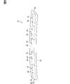
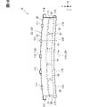
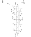
- the visor hood 50 has a hood body 120 and connecting portions 111-113.
- the visor hood 50 is connected to the instrument panel 102 by connecting portions 111-113.
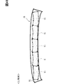
- the hood body 120 forms a main part of the visor hood 50 and has a horizontally long plate shape as a whole.
- the hood body 120 forms a hood front surface 51 , a hood rear surface 52 , a hood concave portion 53 , a hood front end portion 57 , a hood base end portion 58 and a hood side end portion 59 .
- the hood distal end portion 57 and the hood proximal end portion 58 extend in the X direction as a whole.
- the hood side end portion 59 forms a side end portion of the image display device 10 .
- a pair of hood-side end portions 59 are included in the visor hood 50 .
- the pair of hood-side end portions 59 are arranged in the X direction.
- the hood side end portion 59 extends in the Y direction and connects the hood front end portion 57 and the hood base end portion 58 .
- the hood side end portion 59 is shorter than the hood front end portion 57 and the hood base end portion 58 and corresponds to the short edge of the case.
- the hood tip 57 and hood base 58 are sometimes referred to as case long edges.
- the hood front end portion 57 corresponds to the case front end portion
- the hood base end portion 58 corresponds to the case base end portion.
- the visor hood 50 as a whole has a curved shape that expands toward the hood tip portion 57 side.
- the hood distal end portion 57 is curved so as to be recessed toward the hood base end portion 58 side, for example, curved.
- the hood tip 57 has a tip apex 57a.
- the tip top portion 57a is located at the most recessed position toward the hood base end portion 58 side in the hood tip portion 57 .
- the tip top portion 57a is located at an intermediate position between the pair of hood side end portions 59 in the hood tip portion 57. As shown in FIG.
- the hood base end portion 58 is curved, for example curved, so as to swell toward the side opposite to the hood front end portion 57 .
- the hood proximal portion 58 has a proximal top portion 58a.
- the base end top portion 58 a is located at a position where the hood base end portion 58 protrudes most toward the side opposite to the hood tip end portion 57 .
- the base end top portion 58 a is located at an intermediate position between the pair of hood side end portions 59 at the hood base end portion 58 .
- a hood horizontal line L1a of the visor hood 50 extends in the X direction as a whole.
- a hood horizontal line L1a is an imaginary center line that passes through the center of the visor hood 50 and extends in the longitudinal direction of the visor hood 50.
- the hood horizontal line L1a curves toward the hood base end portion 58 so as to swell in the Y direction.
- the hood horizontal line L1a extends in the X direction so as to span the pair of hood-side end portions 59, and corresponds to a longitudinal bending line.
- the hood horizontal line L1a is curved along both the hood distal end portion 57 and the hood proximal end portion 58, for example, curved.
- the hood horizontal line L1a passes through the side end center C1 of the hood side end portion 59 .
- the side end center C ⁇ b>1 is located at an intermediate position between the hood front end portion 57 and the hood base end portion 58 at the hood side end portion 59 .
- the longitudinal direction is the X direction
- the lateral direction is the Y direction.
- a hood vertical line L1b of the visor hood 50 extends linearly in the Y direction along the hood side end portion 59 .
- a hood vertical line L1b is an imaginary center line that passes through the center of the visor hood 50 and extends in the lateral direction of the visor hood 50 , and is located at an intermediate position between the pair of hood base ends 58 .
- the hood front end portion 57 has a front end top portion 57a at a position through which the hood vertical line L1b passes.
- the hood base end portion 58 has a base end top portion 58a at a position through which the hood vertical line L1b passes.
- the hood body 120 has a body base portion 121 and a body frame portion 122 .
- the main body base portion 121 is formed in a plate shape, and the main body frame portion 122 is formed in a frame shape.
- the main body base portion 121 and the main body frame portion 122 are arranged side by side in a direction perpendicular to the Z direction.
- the main body frame portion 122 protrudes from the main body base portion 121 toward the hood front surface 51 , thereby forming a hood concave portion 53 .
- a concave bottom surface 54 is formed by the main body base portion 121 and a concave wall surface 55 is formed by the main body frame portion 122 .
- the thickness dimension of the body frame portion 122 is larger than the thickness dimension of the body base portion 121 . That is, the body frame portion 122 is thicker than the body base portion 121 .
- the hood back surface 52 is formed by the body base portion 121 .
- a hood front surface 51 , a hood front end portion 57 , a hood base end portion 58 and a hood side end portion 59 are formed by the body frame portion 122 .
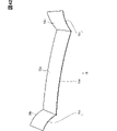
- the visor hood 50 is curved in the Z direction so as to bulge upward so that the upper end is between a pair of hood side end portions 59, for example, curved. .
- the main body base portion 121 of the visor hood 50 is curved in the Z direction so as to expand upward.
- the main body base portion 121 is curved so as to protrude upward, and has an arch shape or a circular arc shape.
- the curvature of the body base portion 121 is uniform in the X direction.
- the arch of the main body base portion 121 is gentle.
- the curvature radius of the main body base portion 121 is larger than the length dimension of the main body base portion 121 in the X direction, for example.
- the hood horizontal line L1a passes through the center of the main body base portion 121 and extends in the X direction.
- the hood horizontal line L1a is curved in the Z direction so as to expand upward, for example, curved.
- the curvature of the hood horizontal line L1a is uniform in the X direction.
- the curvature radius of the hood horizontal line L1a is larger than the length dimension of the main body base portion 121 in the X direction, for example.
- Both the hood back surface 52 and the concave bottom surface 54 are curved along the hood horizontal line L1a.
- the hood horizontal line L1a corresponds to an upward bending line.
- a hood vertical line L1c is an imaginary center line extending in the Z direction through the center of the main body base portion 121 and is located at an intermediate position between the pair of hood base end portions 58 .
- the upper end is at the highest position in the Z direction, and the lower end is at the lowest position in the Z direction.
- the upper end portion of the main body base portion 121 includes a distal top portion 57a and a proximal top portion 58a. In the body base portion 121, the distal top portion 57a and the proximal top portion 58a correspond to the upper end portion.
- connecting portions 111 to 113 connect the hood body 120 to the inner portion 102b and the side portion 102c of the instrument panel 102. As shown in FIG. The connecting portions 111 to 113 positionally hold the hood body 120 with respect to the instrument panel 102 .
- the connecting portions 111 to 113 are portions provided with receiving portions for receiving fasteners or engaging portions.
- Each of the connecting portions 111 to 113 has, for example, ear portions projecting laterally from the hood body 120 in a direction orthogonal to the Z direction, and receiving portions provided on the ear portions.
- the fasteners are fasteners such as bolts, and fasten the visor hood 50 and the instrument panel 102 while being inserted into the receiving portions of the connecting portions 111 to 113 .
- the engaging portion is a portion such as a clip provided on the instrument panel 102, and is a protrusion that engages by being pulled into the receiving portion.
- the receiving portion is a hole or recess into which the fastener or engaging portion is inserted, and is arranged, for example, in the center of the ear portion.
- the positions of the connecting portions 111 to 113 are the positions where the visor hood 50 and the instrument panel 102 are connected.
- the connecting portions 111-113 are sometimes referred to as holding fastening portions.
- the connecting parts 111 to 113 are arranged along the outer peripheral edge of the hood body 120 .
- the outer connecting portion 111 and the inner connecting portion 112 connect the hood base end portion 58 to the inner portion 102b and correspond to base end connecting portions.
- a plurality of outer connecting portions 111 and inner connecting portions 112 are arranged along the hood base end portion 58 .
- the outer connecting portion 111 and the inner connecting portion 112 protrude from the hood body 120 toward the side opposite to the hood tip portion 57 .
- the outer connecting portion 111 is provided outside the inner connecting portion 112 in the X direction. That is, the outer connecting portion 111 is provided at a position closer to the hood-side end portion 59 than the inner connecting portion 112 is.
- the outer connecting portion 111 is provided for each of the pair of hood-side end portions 59 .
- the pair of outer connecting portions 111 are arranged along the hood base end portion 58 . Both of the pair of outer connecting portions 111 are positioned apart from the hood side end portion 59 toward the hood vertical line L1b.
- the outer connecting portion 111 is positioned closer to the hood side end portion 59 than the hood vertical line L1b in the X direction.
- the outer connecting portion 111 corresponds to a base connecting portion and is sometimes referred to as a main holding fastening portion.
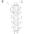
- a plurality of inner connecting portions 112 are provided between a pair of outer connecting portions 111 in the X direction. These inner connecting portions 112 are arranged along the hood base end portion 58 . All of the plurality of inner connecting portions 112 are provided on the opposite side of the hood front end portion 57 from the outer connecting portion 111 in the Y direction. The inner connecting portion 112 is at a position shifted in the Y direction with respect to the outer connecting portion 111 .
- the inner connecting portion 112 corresponds to a displaced connecting portion and is sometimes called a sub-holding fastening portion.
- the plurality of inner connecting portions 112 include an intermediate connecting portion 112a.
- the intermediate connecting portion 112a is the inner connecting portion 112 arranged at a position through which the hood vertical line L1b passes.
- the intermediate connecting portion 112 a is arranged at an intermediate position between the pair of hood side end portions 59 at the hood base end portion 58 .
- the intermediate connecting portion 112 a is located on the side opposite to the hood tip portion 57 most among the plurality of inner connecting portions 112 . Note that even if the intermediate connecting portion 112a is slightly shifted in the X direction from the intermediate position of the pair of hood side end portions 59, it is sufficient that the hood vertical line L1b passes through a portion of the intermediate connecting portion 112a.
- the outer connecting portion 111 is arranged closer to the hood tip portion 57 than the intermediate connecting portion 112a in the Y direction. In the Y direction, the outer connecting portion 111 is positioned closer to the distal top portion 57a than to the proximal top portion 58a. In the Y direction, the distance Db between the outer connecting portion 111 and the tip top portion 57a is smaller than the distance Da between the intermediate connecting portion 112a and the tip top portion 57a.
- the front connecting portion 113 connects the hood side end portion 59 to the side portion 102c.
- One front connecting portion 113 is provided on each of the pair of hood-side end portions 59 .
- the front connecting portion 113 protrudes laterally from the hood-side end portion 59 .
- the front connecting portion 113 corresponds to a short edge connecting portion and is sometimes referred to as left and right end fastening portions.
- the front connecting portion 113 is provided at a position spaced from the hood base end portion 58 toward the hood front end portion 57 at the hood side end portion 59 .
- the front connecting portion 113 is located between the hood tip portion 57 and the hood base end portion 58 and is spaced from both the hood tip portion 57 and the hood base end portion 58 .
- the front connecting portion 113 is located at an intermediate position between the hood distal end portion 57 and the hood proximal end portion 58 at the hood side end portion 59, for example.
- An intermediate position for the front connecting portion 113 is a position where the front connecting portion 113 straddles the side end center C1 in the Y direction.
- This intermediate position is a position where the hood horizontal line L1a passes through a portion of the front connecting portion 113. As shown in FIG. In the Y direction, the front connecting portion 113 is positioned closer to the hood distal end portion 57 than to the hood proximal end portion 58 .
- the positions of the connecting portions 111 to 113 are set at the respective centers.
- the outer connecting portion 111 and the inner connecting portion 112 may protrude outside the hood base end portion 58 in the Y direction, or may be positioned inside the hood base end portion 58. good.
- the front connecting portion 113 may be located outside the hood side end portion 59 in the X direction, or may be located inside the hood side end portion 59 .
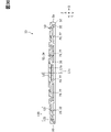
- a plurality of displays 20 are arranged along the hood horizontal line L1a.
- the displays 20 are lined up along both the hood distal end 57 and the hood proximal end 58 .
- the display 20 extends in the direction in which the hood horizontal line L1a extends.
- One of the two adjacent displays 20 is tilted with respect to the other.
- the relative tilt angle of one of the two adjacent displays 20 with respect to the other is the same for each of the multiple sets. For example, all the displays 20 have the same relative tilt angle, for example, 10 degrees each when viewed sequentially from the display 20 at one end in the X direction.
- each horizontal display line L2a extends in the X direction as a whole.
- the display horizontal line L2a extends linearly along the hood horizontal line L1a.
- the display horizontal line L2a is an imaginary center line passing through the center of the display 20 and extending along the long side of the display front surface 21 .
- One display horizontal line L2a of the two adjacent displays 20 is inclined with respect to the other display horizontal line L2a.
- the display vertical line L2b of the display 20 extends linearly in the Y direction, similar to the hood vertical line L1b.
- the display vertical line L2b is an imaginary center line that passes through the center of the display 20 and extends along the short side of the display front surface 21 .
- respective display vertical lines L2b extend parallel to each other.
- the plurality of displays 20 includes a display 20 centered on the visor hood 50 in the Y direction.
- a display vertical line L2b of the display 20 coincides with the hood vertical line L1b.
- the display vertical line L2b corresponds to the display center line.
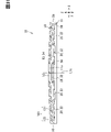
- the base end connecting portions such as the outer connecting portion 111 and the inner connecting portion 112 are individually provided for each of the multiple displays 20 .
- the outer connecting portion 111 and the inner connecting portion 112 are arranged at a position in the hood base end portion 58 through which the display vertical line L2b passes.
- a center line extending in the Y direction through the centers of the outer connection portion 111 and the inner connection portion 112 coincides with the display vertical line L2b.
- one of the outer connecting portion 111 and the inner connecting portion 112 is arranged at a position through which each of the plurality of display vertical lines L2b passes.
- the multiple displays 20 are arranged along the hood horizontal line L1a so that the displays 20 at both ends in the Y direction are arranged at the lowest position.
- the multiple displays 20 are arranged so as to form a shape that bulges upward as a whole. All of these displays 20 are connected to each other through the heat insulating portion 30 , the radiator plate portion 41 and the visor hood 50 . That is, the multiple displays 20 are indirectly connected to each other.
- the plurality of displays 20 are arranged side by side in the image display device 10 .
- a wide display area can be provided by one visor hood 50 on the instrument panel 102, such as enlarging the viewing surface Sv.
- a virtual image Vi displayed by the occupant on the reflecting surface 16 is used instead of a real image method in which the occupant directly visually recognizes the cover front surface 61 and the display surface 22. Therefore, the image V is visually recognized. can enhance sexuality.
- the image display device 10 since the display surface 22 faces downward, it is difficult for external light such as sunlight to directly hit the display surface 22 . Therefore, it is possible to prevent the visibility of the virtual image Vi from deteriorating due to external light.
- the virtual image Vi is displayed at a position farther than the reflecting surface 16 for the occupant, for example, when the driver who has adjusted his eyes to a distant position in front of the vehicle moves his eyes to the virtual image Vi, it is possible for the driver to drive.
- a person can visually recognize the virtual image Vi from a distant viewpoint. Therefore, when a passenger such as a driver visually recognizes the virtual image Vi, the load for adjusting the focus of the eyes can be reduced.
- the virtual image Vi can be displayed as long as the reflecting mirror 15 can be installed. Therefore, the viewing plane Sv for viewing the image V can be more freely set in position.
- the front connecting portion 113 is provided at a position spaced apart from the hood base end portion 58 toward the hood tip portion 57 side.
- the front connecting portion 113 can prevent the visor hood 50 from being deformed such that the hood tip portion 57 moves vertically due to an external force or its own weight. Therefore, it is possible to suppress the deformation of the visor hood 50 and the concentration of stress on the display 20 and the occurrence of an abnormality in the display 20 .
- the image display device 10 is arranged in a special manner in which it is laid down at an angle close to horizontal in order to realize the virtual image method.
- the image display device 10 is placed on the instrument panel 102 at an angle close to the vertical in order to realize the real image method. likely to occur.
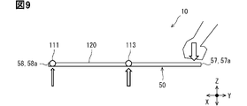
- a bending load is applied to the visor hood 50 when an occupant casually puts his or her hand on the instrument panel 102 .
- a bending load may be applied to the visor hood 50 due to the weight of the display 20 or the like.
- an external force is applied to the visor hood 50 to push down the hood front end portion 57 such as the front end top portion 57a.
- the stress due to the external force is dispersed and transmitted to the outer connecting portion 111, the inner connecting portion 112, and the front connecting portion 113.
- the front connecting portion 113 can prevent the visor hood 50 from bending or deforming so that the hood tip portion 57 moves downward.
- the front connecting portion 113 is closer to the hood tip portion 57 than the outer connecting portion 111 and the inner connecting portion 112 . Therefore, the stress applied to the front connecting portion 113 tends to be greater than the stress applied to the outer connecting portion 111 and the inner connecting portion 112 . Therefore, the front connecting portion 113 can prevent excessively large stress from being applied to the outer connecting portion 111 and the inner connecting portion 112 . Therefore, the front connecting portion 113 can prevent the outer connecting portion 111 and the inner connecting portion 112 from being deformed by the stress.
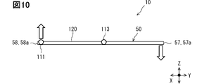
- a rotational moment is generated in the visor hood 50 due to the external force applied to the hood tip portion 57 .
- the outer connecting portion 111 and the inner connecting portion 112 are affected by the rotational moment.
- a pushing force is generated in the opposite direction. Therefore, even if a rotational moment is generated with respect to the visor hood 50 , the visor hood 50 can be maintained in an appropriate state by the outer connecting portion 111 , the inner connecting portion 112 and the front connecting portion 113 .
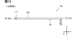
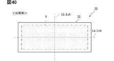
- a comparative example 10x different from the present embodiment is assumed.
- the visor hood 50 does not have the front connecting portion 113 .
- Comparative Example 10x as shown in FIG. 14, when a downward external force is applied to the hood tip portion 57, the stress due to this external force is directly transmitted to the outer connecting portion 111 and the inner connecting portion 112. FIG. Therefore, there is concern that excessively large stress is applied to the outer connecting portion 111 and the inner connecting portion 112 .
- the visor hood 50 is arranged so that the display surface 22 faces downward.
- the image display device 10 vibrates as the vehicle 100 travels. In the vehicle 100, the vibration in the vertical direction tends to be greater than the vibration in the longitudinal direction of the vehicle and the vibration in the width direction of the vehicle.
- the image display device 10 which is arranged in a lying state with an increased viewing surface Sv and a thinner visor hood 50, is likely to bend or deform due to vibration in the vertical direction.
- the image display device 10 with the display surface 22 facing downward is susceptible to vertical vibrations generated in the vehicle 100 .
- the virtual image method in which both the display surface 22 and the reflection surface 16 vibrate tends to have a greater influence of the vibration on the viewing surface Sv.
- deflection of the visor hood 50 due to vibration, displacement of the display surface 22 due to vibration, and display blur due to resonance tend to increase.
- the front connecting portion 113 is provided between the hood tip portion 57 and the outer connecting portion 111 and the inner connecting portion 112 in the Y direction.
- the front connecting portion 113, the outer connecting portion 111, and the inner connecting portion 112 are considered to be fulcrums of vibration in the Y direction. .
- the front connecting portion 113 not the outer connecting portion 111 and the inner connecting portion 112 becomes the fulcrum of vibration. Therefore, even in the image display device 10 in which the separation distance between the hood front end portion 57 and the hood base end portion 58 is increased as the visor hood 50 is enlarged, the swing width Sw of the hood front end portion 57 can be reduced. Therefore, problems caused by vibration, such as bending of the visor hood 50 and blurring of the display, can be suppressed.
- the visor hood 50 is attached to the instrument panel 102 while the image display device 10 is mounted on the vehicle 100 .
- the visor hood 50 of the vehicle 100 is likely to be vibrated. Therefore, a configuration capable of suppressing problems caused by vibration such as bending of the visor hood 50 and blurring of the display is effective for the image display device 10 mounted on the vehicle 100 from the viewpoint of protecting the display 20 from vibration.
- the outer connecting portion 111 and the inner connecting portion 112 serve as fulcrums of vibration for the hood tip portion 57 .
- the swing width Swx of the hood tip portion 57 is larger than the swing width Sw of the hood tip portion 57 in this embodiment.
- the stress is concentrated on the display 20 due to the bending of the visor hood 50, the display 20 may become abnormal.
- the visor hood 50 is held by the instrument panel 102 below the front windshield 106 .
- the posture of the visor hood 50 may not be stable.
- the cantilever support of the visor hood 50 is eliminated by the front connecting portion 113, the posture of the visor hood 50 can be stabilized.
- the hood distal end portion 57 may be displaced downward and the load on the hood proximal end portion 58 may be amplified.
- the front connecting portion 113 eliminates the visor hood 50 from being supported like a cantilever beam. Therefore, problems such as downward displacement of the hood distal end portion 57 and amplification of the load on the hood proximal end portion 58 can be eliminated.
- the visor hood 50 has the front connecting portion 113 but does not have the outer connecting portion 111 and the inner connecting portion 112 .
- the hood base end portion 58 is not connected to the instrument panel 102
- the pair of hood side end portions 59 are connected to the instrument panel 102 . That is, the visor hood 50 is held at its left and right ends.
- the visor hood 50 will be in a state like a beam supported at both ends, and will be weak against bending and likely to resonate.
- the visor hood 50 is prevented from being like a beam supported at both ends by the outer connecting portion 111 and the inner connecting portion 112 . Therefore, it is possible to prevent the visor hood 50 from becoming weak against bending and from easily resonating.
- the front connecting portion 113 is provided at the hood side end portion 59 at a position spaced apart from the hood distal end portion 57 toward the hood base end portion 58 side. Therefore, for example, when an external force is applied to the hood front end portion 57 , the external force is likely to be dispersed among the front connecting portion 113 , the outer connecting portion 111 and the inner connecting portion 112 .
- the front connecting portion 113 is located at an intermediate position between the hood front end portion 57 and the hood base end portion 58, the external force applied to the hood front end portion 57 is applied to the front connecting portion 113, the outer connecting portion 111, and the inner connecting portion. 112 can be reliably distributed. Therefore, application of an excessively large stress to the front connecting portion 113 can be suppressed.
- the outer connecting portion 111 and the inner connecting portion 112 are arranged along the hood base end portion 58 and provided at positions shifted in the Y direction.
- an external force applied to the tip top portion 57a is easily transmitted to the outer connecting portion 111 or the inner connecting portion 112, whichever is closer to the tip top portion 57a. Therefore, deformation of the visor hood 50 such that the tip top portion 57a moves downward can be suppressed by the outer connection portion 111 and the inner connection portion 112, whichever is closer to the tip top portion 57a.
- the outer connection portion 111 is positioned closer to the tip top portion 57a than the inner connection portion 112 in the Y direction. Can be placed close to each other. Moreover, since the inner connecting portion 112 is arranged between the pair of outer connecting portions 111, each of the pair of outer connecting portions 111 can be arranged at a position closer to the tip top portion 57a than the inner connecting portion 112 in the Y direction. Therefore, for example, when an external force is applied to the tip top portion 57a, the outer connection portion 111 can prevent the visor hood 50 from deforming so that the tip top portion 57a moves in the vertical direction.
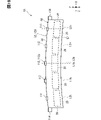
- a comparative example 10y different from the present embodiment is assumed.
- the hood base end portion 58 is not bent in the Y direction, and the positions of the outer connecting portion 111 and the inner connecting portion 112 are not shifted in the Y direction.
- the separation distance Db between the outer connecting portion 111 and the tip top portion 57a is the same as the separation distance Da between the intermediate connecting portion 112a and the tip top portion 57a.
- the outer connecting portion 111 will not provide enough restraining force against the deformation of the visor hood 50 such that the tip top portion 57a moves downward.
- the separation distance Db is smaller than the separation distance Da, the outer connecting portion 111 is prevented from deforming the visor hood 50 such that the tip top portion 57a moves downward. can increase power.
- the outer connecting portion 111 and the inner connecting portion 112 are provided at positions overlapping the display vertical line L2b.
- the outer connecting portion 111 and the inner connecting portion 112 can prevent the display 20 from deforming so that the center of the display 20 moves in the vertical direction.
- the image V displayed by the display 20 it is considered that various information is displayed at a position near the center of the image V, and the background is displayed at a position farther from the center of the image V in many cases. Therefore, the suppression of vertical movement of the center of the display 20 by the outer connecting portion 111 and the inner connecting portion 112 is effective in improving the visibility of the image V and the virtual image Vi.
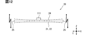
- the visor hood 50 is bent upward so that the upper end portion is present between the pair of hood side end portions 59 .
- the external force and its own weight applied to the visor hood 50 become a compressive force that compresses the visor hood 50 downward. Therefore, it is possible to suppress deformation of the visor hood 50 so as to bend downward. Therefore, it is possible to suppress deformation of the visor hood 50 such that the hood tip portion 57 and the like move partially downward.
- the visor hood 50 is curved as a whole and has an arch shape, it can reliably exert a compressive force against an external force and its own weight.
- the visor hood 50 has the main body base portion 121 and the main body frame portion 122 .
- the portion of the visor hood 50 where the body frame portion 122 is provided is larger in thickness than the body base portion 121 by the body frame portion 122 . Therefore, the portion of the visor hood 50 that overlaps the display 20 can be made thinner by the main body base portion 121 .
- the portion of the visor hood 50 that does not overlap the display 20 can increase the strength and rigidity of the visor hood 50 by the body frame portion 122 .
- the multiple displays 20 are arranged along the hood horizontal line L1a while being connected to each other via the visor hood 50 . That is, a plurality of displays 20 are arranged in an arch shape.
- the external force and own weight applied to the multiple displays 20 and the visor hood 50 become compressive forces that compress the multiple displays 20 and the visor hood 50 downward. Therefore, deformation of the visor hood 50 can be suppressed by arranging the plurality of displays 20 .
- the arrangement of the displays 20 can prevent the visor hood 50 from deforming such that the hood tip portion 57 and the like partially move downward.
- the horizontal display line L2a in the display 20 becomes a vibration axis that vibrates vertically.
- the multiple displays 20 are arranged so as to be curved in the Y direction along the horizontal hood line L1a. Therefore, for example, when vibration is applied to the image display device 10, the vibration axes of the plurality of displays 20 do not match each other. Therefore, it is possible to suppress resonance of vibrations generated in each of the plurality of displays 20 . In addition, the vibration generated in each of the multiple displays 20 can be easily reduced.
- one display horizontal line L2a of the two adjacent displays 20 is inclined with respect to the other display horizontal line L2a.
- These display horizontal lines L2a do not coincide with each other because they have different inclination angles. For this reason, even if two adjacent displays 20 vibrate with their respective display horizontal lines L2a as vibration axes, the tilt angles of these vibration axes do not match, making it difficult for these displays 20 to resonate.
- a plurality of displays 20 are arranged in an arch shape along the curved hood horizontal line L1a. Therefore, in two adjacent displays 20, one has an inclination angle in each direction of roll, pitch, and yaw with respect to the other. Two adjacent displays 20 are devisedly arranged so that these displays 20 are displaced from one beam. Therefore, it is possible to prevent two adjacent displays 20 from resonating like one beam. In addition, the vibration generated in each of the two adjacent displays 20 can be easily reduced individually.
- the visor hood 50 is curved so as to bulge upward so that the upper end portion is between the pair of hood side end portions 59, so that the external force applied to the visor hood 50 and its own weight are compressed. It becomes easy to act on the visor hood 50 as a force. Therefore, even if an external force is applied to the visor hood 50, the shape of the visor hood 50 can be properly maintained. Therefore, the curved shape of the visor hood 50 can prevent the visor hood 50 from deforming and causing an abnormality in the display 20 .
- the visor hood 50 has a curved arch shape, the external force and its own weight on the visor hood 50 can more reliably act as a compressive force. Therefore, the moment of inertia of the area tends to increase against the pressing load from the hood back surface 52 due to external force, self weight, or the like. Therefore, bending strength such as bending rigidity and bending strength of the visor hood 50 can be increased. By increasing the bending strength of the visor hood 50 in this way, it is possible to reduce the occurrence of vibration and resonance of the visor hood 50 even with respect to vehicle vibration.
- the visor hood 50 may deform such that the vicinity of the center of the visor hood 50 moves downward. In this configuration, there is concern that stress will concentrate on the display 20 as the visor hood 50 deforms, causing an abnormality in the display 20 .
- both the hood back surface 52 and the concave bottom surface 54 are bent upward.
- the visor hood 50 can be curved to expand upward.
- the curvature of the hood back surface 52 and the curvature of the concave bottom surface 54 are the same, the external force and the weight of the visor hood 50 can more reliably act as a compressive force.
- the hood side end portion 59 is connected to the instrument panel 102 as the lower end portion of the visor hood 50 .
- the supporting force with which the instrument panel 102 supports the hood-side end portion 59 resists the compressive force generated in the visor hood 50 , thereby suppressing deformation of the visor hood 50 .
- a plurality of displays 20 are arranged in the X direction along the horizontal hood line L1a while being connected to each other.
- the upwardly curved portion of the image display device 10 can be formed by a plurality of displays 20 . Therefore, the external force and its own weight applied to the visor hood 50 tend to act on the multiple displays 20 as compressive force. Therefore, even if an external force is applied to the visor hood 50 , the shape of the visor hood 50 can be properly maintained by the multiple displays 20 . As a result, it is possible to prevent the visor hood 50 from deforming and causing an abnormality in the display 20 by bending the display 20 and interconnecting the displays 20 .
- the multiple displays 20 are connected to each other via the visor hoods 50 .
- the visor hood 50 in addition to the multiple displays 20 forms an upward curved portion of the image display device 10 . Therefore, the visor hood 50 can be used in addition to the multiple displays 20 as a portion for suppressing deformation of the visor hood 50 .
- one of the two adjacent displays 20 is inclined with respect to the other while being connected to each other. Therefore, in a configuration in which a plurality of displays 20 form an upwardly curved portion of the image display device 10, the plurality of displays 20 can be arranged so as to extend along the curve of this portion. Therefore, the deterrent force against deformation of the visor hood 50 can be enhanced by the orientation of each of the multiple displays 20 .
- the plurality of display surfaces 22 are arranged along the reflecting surface 16 while facing the reflecting surface 16 .
- the image V displayed on each of the multiple display surfaces 22 is displayed as multiple virtual images Vi by the reflecting surface 16 . Therefore, it is possible for the passenger to collectively view the plurality of virtual images Vi on the single reflecting surface 16 . Since the reflecting surface 16 is the viewing surface Sv for the passenger, the viewing surface Sv can be enlarged in the virtual image display device 11 .
- the virtual image Vi displayed by the image light is more conspicuous than the virtual image V23 in which only the frame surface 23 is reflected. Therefore, it is possible to reduce the conspicuousness of the virtual image gap area on one viewing surface Sv that displays a plurality of virtual images Vi.
- the virtual image gap area is an area indicating the gap between adjacent virtual images Vi. Therefore, it is possible to prevent the occupant from having a sense of discomfort in the virtual image gap area when the occupant visually recognizes the viewing surface Sv. In other words, it is possible to enhance the seamlessness of the plurality of virtual images Vi viewed from the viewing surface Sv.
- a self-luminous display unit is used as the display 20
- leakage of backlight from black portions of the image V can be avoided.
- the display front surface 21 leakage of backlight from the boundary between the outer peripheral edge of the display surface 22 and the inner peripheral edge of the frame surface 23 is avoided. Therefore, it is possible to prevent the frame surface 23 from being conspicuous due to the light of the backlight in the virtual image gap area. Therefore, the seamless feeling on the viewing surface Sv can also be enhanced by preventing light leakage from the backlight.
- a plurality of displays 20 are arranged in the device width direction. With this configuration, it is possible to prevent image light emitted from one of the two displays 20 adjacent to each other from being blocked by the other display 20 . Therefore, it is possible to prevent the virtual image gap area from being conspicuous due to the blocking of the image light.
- the frame surfaces 23 of the multiple displays 20 have the same color.
- the virtual image V23 of the frame surface 23 can be made uniform in the degree to which the virtual image V23 of the frame surface 23 is inconspicuous for the plurality of displays 20 . Therefore, when a plurality of virtual images V23 are displayed on the viewing surface Sv of the frame surface 23, it is possible to prevent only some of the virtual images V23 from standing out.
- the visor hood 50 that covers the display back surface 24 is in a state of spanning over the multiple displays 20 . Therefore, the visor hood 50 can prevent the plurality of displays 20 from being displaced. For example, the visor hood 50 can prevent the two adjacent display surfaces 22 from being relatively displaced and the two virtual images Vi displayed by these display surfaces 22 to be displaced.
- the visor hood 50 spans over the pair of A-pillars 108.
- the portion where the visor hood 50 is fixed to the instrument panel 102 can be arranged at a position as close to the A-pillar 108 as possible. Therefore, the support strength of the visor hood 50 by the instrument panel 102 can be increased.
- the visor hood 50 in the vehicle interior 101 can be made as large as possible in the vehicle width direction. Therefore, the number of image display devices 10 accommodated in the visor hood 50 can be increased.
- the viewing surface Sv which is the reflecting surface 16, can be increased in size.
- the visor hood 50 is a member attached to the instrument panel 102 . Therefore, it is possible to prevent the visor hood 50 from degrading the design of the passenger compartment 101 . Therefore, the visor hood 50 can enhance the design of the passenger compartment 101 . In particular, in a configuration in which the visor hood 50 is also enlarged in accordance with an increase in the size of the visible surface Sv, the visor hood 50 tends to stand out in the vehicle interior 101 . Therefore, it is effective to improve the design of the passenger compartment 101 by using the visor hood 50 .
- the hood side end portion 59 is provided with only one front connecting portion 113 as a short edge connecting portion.
- the hood side end portion 59 is provided with a plurality of short edge connecting portions. Configurations, actions, and effects not specifically described in the second embodiment are the same as those in the first embodiment. 2nd Embodiment demonstrates centering on a different point from the said 1st Embodiment.
- the visor hood 50 has a rear connecting portion 114 as a short edge connecting portion in addition to the front connecting portion 113 .
- Both the front connection portion 113 and the rear connection portion 114 are provided on each of the pair of hood side end portions 59 .
- the rear connecting portion 114 is provided between the front connecting portion 113 and the hood base end portion 58 .
- the front connecting portion 113 corresponds to the first connecting portion
- the rear connecting portion 114 corresponds to the second connecting portion.
- the rear connecting portion 114 connects the hood side end portion 59 to the side portion 102c.
- the back connecting portion 114 has the same structure as the connecting portions 111 to 113, such as having an ear portion and a receiving portion.
- One rear connecting portion 114 is provided for each of the pair of hood-side end portions 59 .
- the inner connecting portion 114 protrudes laterally from the hood-side end portion 59 .
- the rear connecting portion 114 corresponds to a short edge connecting portion and is sometimes referred to as left and right end fastening portions. Since the outer connecting portion 111 is separated from the hood side end portion 59 toward the hood vertical line L1b, the inner connecting portion 114 is separated from the outer connecting portion 111 toward the hood side end portion 59 side.
- the back connecting portion 114 is provided on the back side of the front connecting portion 113 at the hood side end portion 59 , and is located at the hood base end portion 58 at the hood side end portion 59 .
- the rear connecting portion 114 extends from the hood base end portion 58 toward the hood front end portion 57 side.
- the inner connecting portion 114 is located at the hood side end portion 59 at a position spaced apart from the side end center C1 toward the hood base end portion 58 side.
- the back connecting portion 114 may be provided at a position spaced apart from the hood base end portion 58 toward the hood front end portion 57 side.
- the back connecting portion 114 may be provided at a position straddling the hood base end portion 58 in the Y direction. In short, the rear connecting portion 114 may be provided closer to the hood base end portion 58 than the front connecting portion 113 at the hood side end portion 59 .
- the front connecting portion 113 is provided closer to the front side than the back connecting portion 114 and is located at the hood tip portion 57 at the hood side end portion 59 .
- the front connecting portion 113 extends from the hood distal end portion 57 toward the hood proximal end portion 58 side.
- the front connecting portion 113 is located at the hood side end portion 59 at a position spaced apart from the side end center C1 toward the hood tip portion 57 side.
- the front connecting portion 113 may be provided at a position spaced apart from the hood distal end portion 57 toward the hood proximal end portion 58 side, as in the first embodiment.
- the front connecting portion 113 may be provided at a position straddling the hood tip portion 57 in the Y direction. In short, the front connecting portion 113 may be provided closer to the hood front end portion 57 than the rear connecting portion 114 at the hood side end portion 59 .
- the rear connecting portion 114 is provided between the front connecting portion 113 and the case base end portion at the hood side end portion 59 .
- the external force is likely to be dispersed between the front connecting portion 113 and the rear connecting portion 114 . Therefore, it is possible to prevent the stress applied to each of the front connection portion 113 and the rear connection portion 114 from becoming excessively large.
- the front connecting portion 113 is positioned closer to the hood tip portion 57 and the rear connecting portion 114 is positioned closer to the hood base end portion 58 .
- the visor hood 50 can be held by the front connecting portion 113 against the external force.
- the position of the visor hood 50 can be held by the inner connecting portion 114 against the external force.
- the external force can be dispersed to the front connection portion 113 and the rear connection portion 114.
- the inner connecting portion 112 is provided on the opposite side of the hood front end portion 57 from the outer connecting portion 111 in the hood base end portion 58 .
- the inner connection portion 112 is provided closer to the hood front end portion 57 than the outer connection portion 111 at the hood base end portion 58 . Configurations, actions, and effects that are not specifically described in the third embodiment are the same as those in the first embodiment. 3rd Embodiment demonstrates centering on a different point from the said 1st Embodiment.
- the visor hood 50 as a whole has a curved shape that expands toward the hood base end portion 58 side.
- the hood distal end portion 57 is curved, for example curved, so as to swell toward the side opposite to the hood proximal end portion 58 .
- the tip top portion 57 a is located at a position where the hood tip portion 57 protrudes most toward the side opposite to the hood base end portion 58 .
- the hood proximal end portion 58 is curved so as to be recessed toward the hood distal end portion 57 side, for example, curved.
- the base end top portion 58 a is located at the most recessed position toward the hood front end portion 57 side in the hood base end portion 58 .
- the hood horizontal line L1a is curved so as to swell in the Y direction toward the hood tip portion 57 side, for example, is curved.
- the inner connecting part 112 is arranged along the hood base end part 58 together with the outer connecting part 111 , and is closer to the hood front end part 57 than the outer connecting part 111 .
- the intermediate connecting portion 112 a is located closest to the hood tip portion 57 among the plurality of inner connecting portions 112 .
- a front connecting portion 113 and a rear connecting portion 114 are provided at the hood side end portion 59 as short edge connecting portions, as in the second embodiment.
- the intermediate connecting portion 112a and the inner connecting portion 114 are provided at positions overlapping each other in the Y direction, for example.
- the front connecting portion 113 is closer to the hood tip portion 57 than both the outer connecting portion 111 and the inner connecting portion 112 are.
- the front connecting portion 113 may not be provided at the hood side end portion 59 .
- Modified Example 2 for example, in the third embodiment, only the rear connecting portion 114 of the front connecting portion 113 and the rear connecting portion 114 is provided at the hood side end portion 59 as shown in FIG.
- only one of the front connecting portion 113 and the rear connecting portion 114 may be provided at the hood side end portion 59 .
- the outer connecting portion 111 and the inner connecting portion 112 of the hood base end portion 58 are provided at positions shifted in the Y direction.
- the inner connecting portion 112 and the outer connecting portion 111 of the hood base end portion 58 are arranged at positions overlapping each other in the Y direction. Configurations, functions, and effects that are not specifically described in the fourth embodiment are the same as those in the first embodiment. 4th Embodiment demonstrates centering on a different point from the said 1st Embodiment.
- the hood base end portion 58 extends straight in the X direction.
- the hood front end portion 57 is bent toward the hood base end portion 58 so as to be recessed.
- the outer connecting portion 111 and the inner connecting portion 112 are arranged along the hood base end portion 58 so as to overlap in the Y direction.
- the outer connecting portion 111 and the inner connecting portion 112 are arranged in a straight line without being displaced in the Y direction.
- both the front connecting portion 113 and the rear connecting portion 114 are provided at the hood side end portion 59, as in the second embodiment.
- the front connecting portion 113 is positioned away from the hood distal end portion 57 toward the hood proximal end portion 58 side.
- the bent shape of the hood tip portion 57 does not have to be recessed toward the hood base end portion 58 side.
- the hood base end portion 58 extends straight in the X direction, and the hood front end portion 57 is located on the side opposite to the hood base end portion 58. It may be bent so as to swell toward the
- the front connecting portion 113 may not be provided at the hood side end portion 59 as in the second modification.
- the hood base end portion 58 extends straight in the X direction, and the rear connection portion 114 of the front connection portion 113 and the rear connection portion 114 is configured to extend straight. is provided at the hood side end portion 59 .
- the outer connecting portion 111 and the inner connecting portion 112 are provided in the hood base end portion 58 at positions through which the display vertical lines L2b pass.
- the outer connecting portion 111 and the inner connecting portion 112 are provided at positions shifted in the X direction from the display vertical line L2b. Configurations, functions, and effects that are not specifically described in the fifth embodiment are the same as those in the first embodiment. In the fifth embodiment, differences from the first embodiment will be mainly described.
- the outer connection portion 111 is located at a position closer to the hood side end portion 59 than the display vertical line L2b that is closest to the hood side end portion 59 among the plurality of display vertical lines L2b.
- the external connecting portion 111 is provided at the hood side end portion 59 at the hood base end portion 58, for example.
- the outer connecting portion 111 may be provided at a position straddling the hood-side end portion 59 in the X direction. Further, the outer connecting portion 111 and the inner connecting portion 114 may be provided integrally with each other.
- the display 20 has a pair of display-side ends 25 . Both of the pair of display-side end portions 25 extend in the Y direction.
- the display-side end portion 25 is a short side portion extending along the short side of the display front surface 21 and spans a pair of long side portions extending along the long side of the display front surface 21 .
- the display side edge 25 may simply be referred to as the side edge 25 .
- Both the outer connecting portion 111 and the inner connecting portion 112 are provided at positions shifted in the X direction from the display vertical line L2b, and are not provided at positions where the display vertical line L2b passes through in the hood base end portion 58. .
- the intermediate connecting portion 112a is not provided at the hood base end portion 58 at the position through which the display vertical line L2b passes.
- Both the outer connection portion 111 and the inner connection portion 112 are provided at positions overlapping the display-side end portion 25 in the Y direction. Both the outer connecting portion 111 and the inner connecting portion 112 are positioned across at least one display-side end portion 25 in the X direction.
- the external connecting portion 111 straddles the display side end portion 25 on the hood side end portion 59 side in the X direction for the display 20 closest to the hood side end portion 59 among the plurality of displays 20 . .
- the inner connecting portion 112 straddles the display-side end portions 25 of the two adjacent displays 20 in the X direction.
- the outer connecting portion 111 and the inner connecting portion 112 are provided at positions overlapping the display-side end portion 25 in the Y direction.
- the outer connecting portion 111 and the inner connecting portion 112 can suppress deformation of the display 20 such that the display-side end portion 25 moves in the vertical direction.
- the vertical movement of the display-side end portion 25 causes the inner connecting portion 112 to move. Suppressed by unit 112 .
- the visibility of the image V and the virtual image Vi displayed on the display surface 22 near the display-side end portion 25 can be improved by the inner connecting portion 112 .
- outer connecting portion 111 and the inner connecting portion 112 may be arranged in a manner in which the first embodiment and the fifth embodiment are combined.
- both the outer connecting portion 111 and the inner connecting portion 112 are provided at a position through which the display vertical line L2b passes and at a position shifted in the X direction from the display vertical line L2b in the hood base end portion 58. good too.
- the curvature of the body base portion 121 is uniform in the X direction.
- the curvature of the body base portion 121 is not uniform in the X direction. Configurations, functions, and effects that are not specifically described in the sixth embodiment are the same as those in the first embodiment. In the sixth embodiment, differences from the first embodiment will be mainly described.
- the portion closer to the hood side end portion 59 is more curved in the Z direction. That is, in the main body base portion 121 and the hood horizontal line L1a, the curvature increases toward the hood side end portion 59 . In the main body base portion 121 and the hood horizontal line L1a, the curvature of the portion through which the hood vertical line L1c passes is the smallest.
- the body base portion 121 and the hood horizontal line L1a are formed in an arch shape by combining a plurality of curvatures.
- a plurality of displays 20 are arranged in the X direction along the concave bottom surface 54 .
- the relative inclination angle of one of the two adjacent displays 20 with respect to the other is greater in the set closer to the hood side end 59 in the X direction.
- the curvature of the main body base portion 121 and the hood horizontal line L1a may be smaller toward the hood side end portion 59 .
- the body base portion 121 and the hood horizontal line L1a do not have to have uniform curvatures in the X direction.
- main body base portion 121 and the hood horizontal line L1a may not have a curved portion as long as they are curved in an arch shape so as to swell upward.
- main body base portion 121 has flat portion 121a and inclined portion 121b.
- the flat portion 121 a extends straight in the X direction and forms a flat surface on the hood rear surface 52 and the concave bottom surface 54 .
- the flat portion 121a is located at a position through which the hood vertical line L1c passes, and is spaced apart from the body frame portion 122 toward the hood vertical line L1c in the X direction.
- the inclined portion 121b extends straight in a direction inclined with respect to the flat portion 121a, and forms an inclined surface on the hood back surface 52 and the concave bottom surface 54. As shown in FIG. A pair of inclined portions 121b are provided via the flat portion 121a in the X direction. Both of the pair of inclined portions 121 b connect the flat portion 121 a and the body frame portion 122 . A portion of the hood back surface 52 formed by the inclined portion 121b faces obliquely upward on the side opposite to the flat portion 121a. A portion of the concave bottom surface 54 formed by the inclined portion 121b faces obliquely downward toward the flat portion 121a.
- the inclined portion 121b may be curved.
- the inclined portion 121b may be curved in an arch shape so as to swell toward the side opposite to the recessed opening portion 56 .
- the curvature of the inclined portion 121b may be uniform in the X direction, or the curvature of the inclined portion 121b may increase or decrease toward the hood-side end portion 59 in the X direction. .
- the body base portion 121 and the hood horizontal line L1a do not have to be arched.
- main body base portion 121 and hood horizontal line L1a extend straight in the X direction.
- ⁇ Modified Example of Display 20> One of the two adjacent displays 20 does not have to be tilted with respect to the other.
- Modified Example 7 for example, in the sixth embodiment, if two adjacent displays 20 are referred to as one set, as shown in FIG. Contains non-tilted non-tilted sets.
- the main body base portion 121 has a flat portion 121a and an inclined portion 121b as in the above-described Modified Example 5, and furthermore, some displays 20 extending parallel to the flat portion 121a have non-inclined sets. include. In a set in which one of two adjacent displays 20 extends parallel to the flat portion 121a and the other extends parallel to the inclined portion 121b, one is inclined with respect to the other. Also in Modification 7, a plurality of displays 20 are arranged in an arch shape as a whole.
- a plurality of sets included in a plurality of displays 20 may all be non-tilted sets.
- Modified Example 8 for example, in the sixth embodiment, as shown in FIG. 29, all of the multiple displays 20 extend in the X direction.
- the main body base portion 121 and the hood horizontal line L1a extend straight in the X direction as in the above modified example 6, and furthermore, all of the plurality of displays 20 are connected to the main body base portion 121 and the hood horizontal line L1a. extends parallel to the In this modified example, a plurality of displays 20 are arranged in series.
- One of the two adjacent displays 20 does not have to be tilted with respect to the other.
- two adjacent displays 20 extend parallel to each other, and one is provided above the other. That is, two adjacent displays 20 are provided at positions shifted from each other in the Z direction.
- the main body base portion 121 is curved so as to bulge upward, and furthermore, the plurality of displays 20 are arranged so as to bulge upward as a whole. is curved.
- all of the multiple displays 20 extend in parallel along the concave opening 56 in the X direction.
- the display 20 closer to the hood vertical line L1c is arranged closer to the concave bottom surface 54 than the display 20 closer to the hood side end portion 59 is.
- the multiple displays 20 are arranged in an arch shape as a whole.
- the image display device 10 can be formed with a plurality of displays 20 in a curved portion that bulges upward. Moreover, since the two adjacent displays 20 extend parallel to each other at this portion, the display surfaces 22 of the respective displays 20 can be arranged parallel to each other. Therefore, the deformation of the visor hood 50 is suppressed by the curved arrangement and interconnection of the plurality of displays 20, and the two adjacent display surfaces 22 are inclined with respect to each other, which reduces the visibility of the image V and the virtual image Vi. can be avoided.
- the multiple displays 20 may be directly connected to each other.
- two adjacent displays 20 are provided so as to partially overlap each other, and are connected to each other at the overlapping portions.
- a portion of the display back surface 24 on one side and a portion of the display front surface 21 on the other side are overlapped with each other while facing each other.
- These displays 20 are fixed to each other by fixtures or the like.
- the plurality of displays 20 are arranged along the hood horizontal line L1a as a whole. In this modification, a plurality of displays 20 are alternately arranged along the hood horizontal line L1a.
- two displays 20 adjacent to each other with one display 20 interposed therebetween are both arranged closer to the concave bottom surface 54 side or the concave opening 56 side than the single display 20 .
- a plurality of displays 20 are arranged in an arch shape as a whole.
- two adjacent displays 20 are provided so that their respective parts overlap each other, and are connected at the mutually overlapping parts.
- the portion of the image display device 10 bent upward can be formed by a plurality of displays 20 without using the visor hood 50 . Therefore, regardless of the shape of the visor hoods 50, the force of restraining the deformation of the visor hoods 50 can be exerted by directly connecting the plurality of visor hoods 50 to each other.
- the multiple displays 20 do not have to be arranged alternately.
- a plurality of displays 20 are arranged such that one display 20 is arranged at the top.
- the arrangement of the plurality of displays 20 as a whole is curved so as to bulge upward.
- the display 20 closer to the hood vertical line L1c is arranged closer to the concave bottom surface 54 than the display 20 closer to the hood side end portion 59.
- the plurality of displays 20 are arranged in an arch shape as a whole.
- a plurality of displays 20 may be arranged at positions separated from each other, or may be connected by a connector or the like without passing through the visor hood 50 .
- two adjacent displays 20 may be connected without the visor hood 50 interposed therebetween.
- Modifications 5 to 11 may be combined in any way.
- modifications 5 and 6 may be selectively applied from the viewpoint of mountability and assembly to the instrument panel 102 according to the shape and specifications of the instrument panel 102 .
- Modifications 7 to 11 may be selectively applied in accordance with the shape and specifications of the visor hood 50 from the viewpoint of mountability and assembly to the visor hood 50 .
- one display horizontal line L2a of the two adjacent displays 20 is inclined with respect to the other display horizontal line L2a.
- one display horizontal line L2a of the two adjacent displays 20 is not inclined with respect to the other display horizontal line L2a. Configurations, functions, and effects that are not specifically described in the seventh embodiment are the same as those in the first embodiment. In the seventh embodiment, differences from the first embodiment will be mainly described.
- the multiple displays 20 are arranged such that the respective display horizontal lines L2a extend in the X direction.
- the horizontal display lines L2a of each of the multiple displays 20 extend parallel to each other.
- an imaginary center line passing through the center of the display 20 and extending along the short side of the display front surface 21 coincides with the display vertical line L2b.
- One of the two adjacent displays 20 is arranged at a position shifted in the Y direction with respect to the other.
- the multiple displays 20 are arranged along the hood front end portion 57 so that one display 20 is arranged closest to the hood base end portion 58 side.
- one display horizontal line L2a is at a position shifted in the Y direction from the other display horizontal line L2a.
- the display 20 closer to the hood vertical line L1b has a horizontal display line L2a that is closer to the hood side end 59 than the horizontal display line L2a of the display 20 closer to the hood side end 59 is. 58 side.
- the horizontal display lines L2a of the two adjacent displays 20 are shifted in the Y direction. These display horizontal lines L2a do not match each other because their positions in the Y direction are different from each other. For this reason, even if two adjacent displays 20 vibrate with their respective display horizontal lines L2a as vibration axes, resonance of these displays 20 is less likely to occur because the positions of these vibration axes do not match.
- the image display device 10 and the reflecting mirror 15 are curved as a whole.
- the visor hood 50 and the reflecting mirror 15 are in a state of being stretched over the pair of A-pillars 108 .
- the visor hood 50 and the reflecting mirror 15 are curved so that their center portions swell toward the front of the vehicle.
- a reflecting surface 16 of the reflecting mirror 15 is a flat surface or a curved surface, and forms one continuous continuous surface.
- Hood front end portion 57 is curved such that a center portion of hood front end portion 57 in the vehicle width direction is recessed toward hood base end portion 58 .
- a plurality of display units 70 are arranged along the hood tip portion 57 .
- a plurality of display units 70 are arranged in the vehicle width direction.
- the display 20 and the circuit board 71 are arranged in the longitudinal direction of the vehicle.
- respective displays 20 are arranged along the hood tip portion 57 .
- they may or may not be inclined with respect to the width direction of the vehicle.
- one display 20 of two adjacent displays 20 may or may not be tilted with respect to the other display 20 .
- illustration of the hood cover 60 is omitted.
- the image display device 10 has a control section 80 and a detection section 83.
- the control unit 80 is electrically connected to each of the multiple displays 20 and controls each of these displays 20 individually.
- the control unit 80 controls the display 20 via, for example, a driver circuit.
- the control unit 80 is, for example, an ECU and corresponds to a control device.
- ECU is an abbreviation for Electronic Control Unit.
- the control unit 80 has a CPU 81 as an arithmetic processing device and a memory 82 as a storage device.
- CPU 81 is a processor.
- the control unit 80 is mainly composed of a microcomputer having, for example, a CPU 81, a memory 82, I/O, and a bus connecting them.
- the control unit 80 executes various processes related to driving the display 20 by executing control programs stored in the memory 82 .
- This memory 82 is a non-transitory tangible storage medium that stores computer-readable programs and data non-temporarily.
- a non-transitional physical storage medium is implemented by a semiconductor memory, a magnetic disk, or the like.
- the detection section 83 is electrically connected to the control section 80 .
- the detection unit 83 detects the brightness of the external light applied to the reflecting surface 16 and outputs a detection signal indicating the brightness to the control unit 80 .
- the detector 83 is provided on the front side of the reflecting surface 16 in the instrument panel 102 .
- the control unit 80 uses the detection signal from the detection unit 83 to measure the brightness of the outside light applied to the reflecting surface 16 as the outside light brightness, and controls the display 20 according to this outside light brightness.
- the control unit 80 adjusts, for example, the color, brightness, image quality, etc. of the image V according to the brightness of the outside light. For example, the control unit 80 sets the lightness and brightness of the image V to be high when the measured value of the external light brightness is high, such as when the reflection surface 16 is illuminated with the setting sun or the morning sun.
- the detection unit 83 may be provided at a position where the brightness of the external light with which the display surface 22 is irradiated is detected. Further, the detection unit 83 may be provided at least one of the position for detecting the brightness of the external light irradiated to the reflecting surface 16 and the position for detecting the brightness of the external light irradiated to the display surface 22. good. In this configuration, the controller 80 measures at least one of the external light brightness on the reflecting surface 16 and the external light brightness on the display surface 22, and controls the display 20 according to the measured external light brightness. .
- a configuration in which the virtual image Vi is distorted includes, for example, a configuration in which the reflecting surface 16 is relatively curved with respect to the display surface 22 in the thickness direction of the device or in the longitudinal direction of the vehicle.
- the control unit 80 performs distortion correction processing to correct the image V so that the virtual image Vi is not distorted.
- the control unit 80 performs, for example, a process of intentionally distorting the image V with respect to the display surface 22 so as to cancel the distortion of the virtual image Vi.
- the controller 80 controls the horizontal center line Lva of the image V to be inclined with respect to the horizontal center line La of the display surface 22 and the vertical center line Lvb of the image V to be the vertical center of the display surface 22. Distortion correction is performed so as to be inclined with respect to the line Lb.
- horizontal center lines Lva and La extend in the horizontal direction of the display surface 22
- vertical center lines Lvb and Lb extend in the vertical direction of the display surface 22
- the horizontal direction is the longitudinal direction
- the vertical direction is the lateral direction.
- the horizontal direction of the display surface 22 is the vehicle width direction
- the vertical direction of the display surface 22 is the vehicle front-rear direction.
- the distortion of the virtual image Vi is eliminated.
- the horizontal center lines Lva of the virtual images Vi become parallel or coincident with each other and extend in the vehicle width direction. become a state.
- the vertical center lines Lvb of the virtual images Vi become parallel or coincide with each other, and extend in the longitudinal direction of the vehicle.
- the image V is not distorted with respect to the display surface 22 as shown in FIG.
- the horizontal center lines Lva and La of the image V and the display surface 22 are parallel or coincide with each other.
- the respective vertical center lines Lvb, Lb are parallel or coincident with each other.
- the virtual image Vi is distorted with respect to both the image V and the reflecting surface 16 as shown in FIG.
- the reflective surface 16 may have a plurality of continuous surfaces instead of being one continuous surface.
- the reflection mirror 15 has a center mirror 15a and a pair of side mirrors 15b and 15c.
- the center mirror 15a extends in the width direction of the vehicle and faces the seat.
- the center mirror 15a is provided between a pair of side mirrors 15b and 15c and connects the side mirrors 15b and 15c.
- the center mirror 15a and the side mirrors 15b and 15c are both plate-shaped.
- one end in the vehicle width direction is formed by the side mirror 15b, and the other end is formed by the side mirror 15c.
- the side mirror 15b is fixed to one of the pair of A pillars 108, and the side mirror 15c is fixed to the other.
- the reflecting surface 16 has a center surface 16a and a pair of side surfaces 16b and 16c.
- the center surface 16a is formed by one plate surface of the center mirror 15a and faces the seat side.
- the side surfaces 16b and 16c are formed by one plate surface of the side mirrors 15b and 15c. Both of the side surfaces 16b and 16c are inclined with respect to the center surface 16a and face the seat side so as to face the center surface 16a side. Therefore, of the two seats arranged in the width direction of the vehicle, the side surface 16b closer to one of the seats can also be easily seen from the other seat. Similarly, the side surface 16c near the other seat is also easy to see from one seat.
- the side surfaces 16b and 16c are bent with respect to the center surface 16a, and the bending angle is, for example, an obtuse angle.
- the side surfaces 16b and 16c are curved, for example, so that their central portions bulge toward the seat.
- One end of the reflecting surface 16 in the vehicle width direction is formed by a side surface 16b, and the other end is formed by a side surface 16c.
- the side surfaces 16b and 16c are capable of displaying an image V captured around the vehicle 100 as a virtual image Vi. For example, when the side surface 16b is on the right side for the driver, an image V of the right side of the vehicle is displayed as the virtual image Vi on the side surface 16b. When the side surface 16c is on the left side of the driver, an image V of the left side of the vehicle is displayed as the virtual image Vi on the side surface 16c.
- the side surfaces 16b and 16c correspond to electronic mirrors that function as side mirrors. Side mirrors include door mirrors and fender mirrors.
- one of the two adjacent displays 20 is arranged closer to the viewer than the other.
- the display 20 arranged on the front side is called a front display 20A
- the display 20 arranged on the back side is called a back display 20B.
- Both the front display 20A and the rear display 20B extend parallel to the concave bottom surface 54 and the cover front surface 61 .
- the multiple displays 20 include two rear displays 20B adjacent to each other with a front display 20A interposed therebetween.
- One side end portion 25 of the front display 20A is on the front side of one of the two rear displays 20B, the rear display 20B.
- the other side end portion 25 is on the front side of the other of the two rear displays 20B.
- a side end portion 25 of the front display 20A is arranged at a position overlapping the rear display 20B in the device thickness direction.
- a side end portion 25 of the front display 20A is arranged on the front side of the display front surface 21 of the rear display 20B.
- the front display 20A is arranged at a position that does not block the image light emitted from the rear display 20B.
- the side end portion 25 of the front display 20A is arranged at a position that overlaps the frame surface 23 of the rear display 20B, but is arranged at a position that does not overlap the display surface 22 of the rear display 20B.
- the plurality of display units 70 includes a front display unit 70A and a rear display unit 70B.
- the front display unit 70A has a front display 20A
- the rear display unit 70B has a rear display 20B.
- the side end portion 25 of the front display 20A is provided at a position overlapping the display surface 22 of the rear display 20B.
- a front display 20A and a rear display 20B are provided with their respective display surfaces 22 facing downward.
- a side end portion 25 of the front display 20A is arranged below the display surface 22 of the rear display 20B.
- the image display device 10 has a display overlapping section 26 .
- the display overlapping portion 26 is a portion where the front display 20A and the rear display 20B overlap in the device thickness direction.
- the display rear surface 24 of the front display 20A and the display front surface 21 of the rear display 20B overlap each other.
- the front display 20A is housed in the visor hood 50 while protruding from the concave opening 56.
- the rear display 20B is housed in the visor hood 50 without protruding from the concave opening 56.
- the rear display 20B has a thickness dimension D1.
- the thickness dimension of the front display 20A is the same as the thickness dimension of the back display 20B.
- a projection dimension D2 of the rear display 20B from the concave opening 56 is smaller than the thickness dimension D1.
- the protrusion dimension D2 is less than half the thickness dimension D1.
- the image display device 10 does not have the hood cover 60 in this embodiment.
- illustration of the heat insulating portion 30 and the heat radiating portion 40 is omitted.
- each of the multiple displays 20 has a display main body 201, a polarizing plate 202 and a display frame portion 203.
- the display main body 201 is, for example, an organic EL display and is formed in a plate shape.
- the polarizing plate 202 is superimposed on the plate surface of the display body 201 and fixed to the display body 201 .
- a polarizer 202 forms the display front surface 21 .
- the polarizing plate 202 forms both the display surface 22 and the frame surface 23 .
- the polarizing plate 202 has, for example, a transmission axis and an absorption axis that are orthogonal to each other, transmits light that has been changed in the direction of the transmission axis, and absorbs light that has been changed in the direction of the absorption axis.
- the display frame portion 203 extends along the outer peripheral edge of the display main body 201 and is formed in a frame shape.
- the display frame portion 203 forms the side edges 25 and the frame surface 23 .
- the display frame portion 203 is made of a resin material or the like.
- the display frame portion 203 is formed by applying paint to the display main body 201 and the polarizing plate 202, for example.
- the display frame portion 203 has a dark color such as black with low brightness. In the display frame portion 203, light reflectivity is low.
- the display frame portion 203 is a reflection suppression portion that suppresses reflection of light. When light such as image light impinges on the display frame portion 203 , the light is less likely to be reflected by the display frame portion 203 . Processing such as applying paint to form the display frame portion 203 is antireflection processing.
- the display frame portion 203 has a frame front portion 203a and a frame edge portion 203b.
- the frame front surface portion 203a is a portion forming the frame surface 23, and overlaps the polarizing plate 202, for example.
- the frame edge portion 203b is a portion that forms the edge surface of the display 20, and overlaps each end surface of the display main body 201 and the polarizing plate 202, for example.
- the side end portion 25 is formed by the frame edge portion 203b.
- the display frame portion 203 of the front display 20A straddles the display surface 22 and the frame surface 23 of the rear display 20B in the device width direction.
- the width dimension W1 of the display overlapping portion 26 is larger than the width dimension W2 of the frame surface 23 formed by the frame front surface portion 203a.
- the distance W3 between the display surface 22 of the front display 20A and the display surface 22 of the rear display 20B is the same as the width dimension W2.
- the separation distance W3 is smaller than the width dimension W1.
- the side end portion 25 of the front display 20A is arranged in front of the frame surface 23 of the rear display 20B.
- at least part of the frame surface 23 of the rear display 20B is exposed between the display surface 22 of the front display 20A and the display surface 22 of the rear display 20B in the device width direction. Therefore, both the frame surface 23 of the front display 20A and the frame surface 23 of the rear display 20B are exposed between the two adjacent display surfaces 22 in the device width direction.
- the separation distance W3 becomes larger than the width dimension W2.
- the entire frame surface 23 of the rear display 20B is hidden behind the front display 20A. Therefore, the frame surface 23 of the rear display 20B is not exposed between the two adjacent display surfaces 22 in the device width direction.
- the separation distance W3 becomes the same as the width dimension W2.
- the width dimension of the virtual image gap area becomes smaller than the configuration in which the separation distance W3 is larger than the width dimension W2 as described above. Therefore, it is possible to prevent the virtual image gap area from being conspicuous when the occupant visually recognizes the virtual image Vi.
- a virtual image gap area is displayed between two adjacent virtual images Vi on the viewing surface Sv.
- the frame surface 23 of the front display 20A is displayed as a virtual image V23.
- this virtual image V23 is displayed so slightly that it is almost invisible to the occupant.
- the virtual image Vi includes an information virtual image Vi1 and a background virtual image Vi2.
- the information virtual image Vi1 is a virtual image that displays various information such as vehicle information.
- the background virtual image Vi2 is a virtual image that displays the background for the information virtual image Vi1.
- the background virtual image Vi2 extends along the virtual image V23 displaying the frame surface 23 and is displayed at a position adjacent to the virtual image V23. It is conceivable that the background virtual image Vi2 is displayed between the information virtual image Vi1 and the virtual image V23.
- the information virtual image Vi1 may be called a first virtual image
- the background virtual image Vi2 may be called a second virtual image.
- the image display device 10 has a control section 80 as in the third embodiment.
- the control unit 80 causes the display 20 to display an image V such that the occupant cannot distinguish between the virtual image V23 showing the frame surface 23 and the background virtual image Vi2.
- the control unit 80 controls the display 20 so that at least one of the hue, saturation, and brightness of the background virtual image Vi2 is the same as or close to the virtual image V23. As a result, it is possible to prevent the virtual image V23 from standing out against the background virtual image Vi2 and causing the occupant to feel uncomfortable.
- the display frame portion 203 is the reflection suppressing portion.
- image light emitted from the rear display 20B is less likely to be reflected by the display frame portion 203 of the front display 20A. Therefore, it is possible to prevent the image light emitted from the rear display 20B from being reflected on the edge surface of the front display 20A, and the reflected light from conspicuous at the boundary between the background virtual image Vi2 and the virtual image V23.
- the side end portion 25 of the front display 20A is provided at a position overlapping the display surface 22 of the rear display 20B in the device thickness direction. Therefore, unlike the configuration in which there is a gap between the front display 20A and the rear display 20B in the device thickness direction, the virtual image reflecting the gap is not included in the virtual image gap area. Therefore, it is possible to prevent the virtual image gap area from being conspicuous to the occupant who visually recognizes the virtual image Vi due to the virtual image of the gap.
- the display frame portion 203 may have a shape that wraps around to the display rear surface 24 side.
- the display frame portion 203 has a frame rear portion 203c in addition to the frame front portion 203a and the frame edge portion 203b.
- the frame back surface portion 203c is provided on the opposite side of the display body 201 from the frame front surface portion 203a.
- the frame back portion 203 c is superimposed on the back side plate surface of the display body 201 .
- the frame edge portion 203b connects the frame front portion 203a and the frame back portion 203c.
- the frame back surface portion 203 c forms part of the display back surface 24 .
- the frame rear surface portion 203c of the front display 20A is arranged at a position straddling the display surface 22 and the frame surface 23 of the rear display 20B in the device width direction. That is, at least a portion of the frame back surface portion 203c of the front display 20A faces the display surface 22 of the rear display 20B.
- the frame rear surface portion 203c is less likely to reflect the image light. Therefore, it is possible to prevent the image light emitted from the rear display 20B from conspicuous at the boundary between the virtual image Vi and the virtual image V23.
- the connecting portions 111 to 114 may protrude from the hood body 120 in the Z direction. Connecting portions 111 to 114 may not protrude from hood body 120 .
- the hood body 120 may be provided with a receiving portion.
- the connecting portions 111 to 114 may be provided with fasteners or engaging portions instead of receiving portions.
- the visor hood 50 may have an upper end at a position shifted in the X direction from the position through which the hood vertical line L1b passes.
- the height positions of the pair of hood-side end portions 59 may be different.
- the visor hood 50 may have a lower end at a position closer to the hood vertical line L1b than the hood side end 59 is.
- the visor hood 50 does not have to be curved as long as it is curved so as to expand in the Z direction.
- the main body base portion 121 and the hood horizontal line L1a may be curved so as to swell upward in stages, or may be curved linearly upward.
- the visor hood 50 may be bent in the Z direction so that one of the hood front end portion 57 and the hood base end portion 58 is the upper end portion.
- the curved manner does not have to be curved.
- at least one of the hood front end portion 57, the hood base end portion 58, and the hood horizontal line L1a may be bent in a stepwise manner in the Y direction, or may be bent linearly in the Y direction. good.
- the hood front end portion 57 and the hood base end portion 58 may be bent in the Y direction so that one end of each of them is the front end or the back end.
- the hood-side end portion 59 may be curved so as to swell or dent in the X direction, or may be curved so as to swell in the Z direction.
- the hood side end portion 59 may be bent in the Z direction so that one end thereof is the upper end portion or the lower end portion, or may be bent in the X direction so that one end thereof is the side end portion.
- a plurality of displays 20 may be arranged vertically.
- the image display device 10 is installed in the vehicle interior 101 so that the device width direction is the vehicle front-rear direction, it is preferable that a plurality of the displays 20 be arranged in the vehicle front-rear direction.
- the image display device 10 may have only one display 20 .
- the display 20 does not have to be housed inside the hood recess 53 as long as the display back surface 24 is covered with the visor hood 50 .
- the visor hood 50 may cover the display rear surface 24 with the hood front surface 51 facing the display rear surface 24 .
- the hood front surface 51 corresponds to the case facing surface.
- the visor hood 50 may not have the body frame portion 122 .
- a configuration in which the entire visor hood 50 is formed by the main body base portion 121 is employed.
- the display 20 may be indirectly fixed to the visor hood 50 through one of the heat insulating portion 30 and the heat radiation plate portion 41 .
- the display 20 may be fixed directly to the visor hood 50 without the heat insulating portion 30 and the heat sink portion 41 interposed therebetween.
- a configuration in which the display 20 is directly fixed to the visor hood 50 includes a configuration in which the display side end portion 25 is fixed to the concave wall surface 55 and a configuration in which the display rear surface 24 is fixed to the concave bottom surface 54 .
- the display 20 and the visor hood 50 may be fixed with an adhesive, screws, or the like.
- one display-side end 25 is arranged on the front side of the adjacent display 20, and the other display-side end 25 is arranged on the back side of the display 20 on the opposite side.
- the displays 20 are inclined with respect to the width direction of the image display device 10 .
- the visor hood 50 may be attached to an interior panel different from the instrument panel 102.
- interior panels include door panels and ceiling panels.
- the visor hood 50 may be connected to a vehicle body such as a vehicle body frame in vehicle 100 by connecting portions 111 to 114 .
- the connecting portions 111 to 114 connect the visor hood 50 to at least one of the interior panel and the vehicle body. In this configuration, at least one of the interior panel and the vehicle body corresponds to the attachment target.
- the heat insulating portion 30 does not have to be joined to the concave bottom surface 54 as long as it is fixed to the visor hood 50 .
- the heat insulation part 30 may be fixed to the visor hood 50 with fasteners such as screws.
- the heat insulating portion 30 may be formed of an air layer.
- the image display device 10 does not have to have at least one of the heat insulation section 30 and the heat radiation section 40 .
- the display back surface 24 may be directly bonded to the concave bottom surface 54 .
- the display 20 may not have the frame surface 23 . That is, the entire display front surface 21 may serve as the display surface 22 .
- Image display device 10 may not have hood cover 60 .
- the display 20 as an image display unit does not have to be self-luminous.
- the display 20 may be a picture element such as a liquid crystal panel.
- the image display device 10 has a light source such as an LED as a backlight.
- the two adjacent display surfaces 22 are shifted in the thickness direction of the device regardless of whether or not the two adjacent displays 20 overlap each other in the thickness direction of the device. may be placed in
- a plurality of reflecting mirrors 15 may be arranged in the device width direction.
- the plurality of reflecting surfaces 16 as a whole form one viewing surface Sv.
- the virtual image display unit may not be the reflecting mirror 15 as long as it can display the image V as the virtual image Vi.
- the virtual image display section may be, for example, a half mirror or a lens member.
- a half mirror has a mirror surface and is a member that both transmits and reflects image light incident on the mirror surface.
- the windshield may be used as the virtual image display unit.
- the configuration is such that image light from the image display device 10 is irradiated onto the windshield.
- the inner surface of the windshield reflects image light to display a virtual image Vi. Therefore, at least part of the inner surface of the windshield becomes the visible surface Sv.
- the vehicle 100 on which the display devices 10 and 11 are mounted includes an automatically operated vehicle capable of both automatic operation and manual operation.
- Vehicles 100 on which the display devices 10 and 11 are mounted include passenger cars, buses, construction vehicles, agricultural machinery vehicles, and the like. Examples of moving objects on which the display devices 10 and 11 are mounted include a train, an airplane, a ship, etc., in addition to the vehicle 100 .
- the display devices 10, 11 may be mounted on a vehicle. Vehicles include mobile vehicles such as the vehicle 100 and stationary vehicles such as game machines.
- the display devices 10 and 11 may be mounted on stationary equipment or equipment.
- the display devices 10 and 11 may be applied to personal digital assistants such as head-mounted displays. In a configuration in which the display devices 10 and 11 are mounted on equipment or equipment different from the vehicle 100 , at least part of the finished surface of these equipment or equipment may be formed by the visor hood 50 .
- a display device (10) having a display surface (22) for displaying an image (V) and attached to an attachment target (102) so that the display surface faces the vertical direction, an image display portion (20) having a display surface and a display back surface (24) opposite the display surface; a display case (50) that covers the back surface of the display and is connected to the mounting object; with The display case is a back surface of the case (52) facing away from the display surface; a case base end portion (58) extending in the longitudinal direction (X) of the case back surface and connected to an object to be attached; a case front end portion (57) provided on the opposite side of the case base end portion in the lateral direction (Y) of the case back surface and extending in the longitudinal direction; a case short edge (59) extending in the lateral direction and bridged between the case base end and the case tip end; A base end connection portion (111, 112) that connects the case base end portion to an attachment target; short edge connecting portions (113, 114) for connecting the short edge of the case to the
- the short edge connecting portion is the first connecting portion (113), and the second connecting portion is provided between the first connecting portion and the case base end portion at the case short edge portion and connects the case short edge portion to the mounting object. (114), the display device of feature A1 or A2.
- the first connecting portion is provided at a position closer to the case distal end than the case proximal end, The display device according to feature A3, wherein the second connecting portion is provided at a position closer to the case proximal end than to the case distal end.
- the base end of the case is bent to swell in the short direction
- the proximal connecting portion has a base connecting portion (111) and a displaced connecting portion (112) provided at a position shifted in the lateral direction with respect to the base connecting portion,
- the display device according to any one of features A1 to A4, wherein the base connecting portion and the displaced connecting portion are arranged along the base end of the case.
- the base end of the case is curved to swell toward the opposite side of the front end of the case, A pair of base connecting portions are provided along the base connecting portion, The display device according to feature A5, wherein the displaced connecting portion is provided between the pair of base connecting portions at a position displaced from the base connecting portion to the side opposite to the front end of the case.
- the vehicle has an interior panel (102) that forms the interior of the passenger compartment (101) as an object to be attached,
- the display device according to any one of features A1 to A10, wherein the display case is a member attached to the interior panel.
- a display device (10) having a display surface (22) for displaying an image (V) and attached to an attachment target (102) so that the display surface faces the vertical direction, an image display portion (20) having a display surface and a display back surface (24) opposite the display surface; a display case (50) that covers the back surface of the display and is connected to the mounting object; with The display case is a back surface of the case (52) facing away from the display surface; a case base end portion (58) extending in the longitudinal direction (X) of the case back surface and connected to an object to be attached; and a case tip (57) provided on the opposite side of the case base end in the lateral direction (Y) of the case back surface and extending in the longitudinal direction, and the upper end (57) is located between the pair of short edges.
- the display device is bent upwardly so that the portions (57a, 58a) are present.
- the display case has a case facing surface (54) facing the display back surface,
- the display case is It has a pair of case short edges (59) extending in the lateral direction, bridging the case base end and the case tip, being the lower end of the display case and connected to the mounting object.
- the display device according to any one of B1 to B3.
- the vehicle has an interior panel (102) that forms the interior of the passenger compartment (101) as an object to be attached,
- the display device according to any one of features B1-B4, wherein the display case is a member attached to the interior panel.
- a display device (10) having a display surface (22) for displaying an image (V) and attached to an attachment target (102) so that the display surface faces the vertical direction, an image display portion (20) having a display surface and a display back surface (24) opposite the display surface; a display case (50) that covers the back surface of the display and is connected to the mounting object; with The display case is a back surface of the case (52) facing away from the display surface; a case base end portion (58) extending in the longitudinal direction (X) of the case back surface and connected to an object to be attached; a case front end portion (57) provided on the side opposite to the case base end portion in the lateral direction (Y) of the case back surface and extending in the longitudinal direction; a pair of case short edges (59) extending in the lateral direction and bridged between the case base end and the case tip end; and Assuming an upward bending line (L1a) as a virtual line that spans a pair of short edges of the case and curves upward to swell,
- One image display unit (20A) of two adjacent image display units (20A, 20B) is provided at a position that does not block image light emitted from the other image display unit (20B).
- the image display section a frame surface (23) extending along the outer periphery of the display surface and facing the reflecting surface together with the display surface;
- the respective frame surfaces of the plurality of image display units have the same color or similar colors.
- a virtual image display device according to any one of features D1 to D4.
- feature D6 Any one of features D1 to D5, comprising a display case (50) covering a display back surface (24) on the side opposite to the display surface of the image display units while being spanned over the plurality of image display units.
- the virtual image display device according to 1.
- FIG. 1 A virtual image display device mounted on a vehicle (100), The virtual image display device according to any one of features D1 to D7, wherein the display case is a member attached to an interior panel (102) forming an interior in a vehicle compartment (101).
Landscapes
- Engineering & Computer Science (AREA)
- Mechanical Engineering (AREA)
- Physics & Mathematics (AREA)
- General Physics & Mathematics (AREA)
- Theoretical Computer Science (AREA)
- Chemical & Material Sciences (AREA)
- Combustion & Propulsion (AREA)
- Transportation (AREA)
- Instrument Panels (AREA)
- Fittings On The Vehicle Exterior For Carrying Loads, And Devices For Holding Or Mounting Articles (AREA)
- Devices For Indicating Variable Information By Combining Individual Elements (AREA)
Abstract
画像表示装置(10)は、ディスプレイ(20)及びバイザフード(50)を有している。ディスプレイ(20)は表示面及びディスプレイ背面を有している。バイザフード(50)は、ディスプレイ背面を覆っており、インパネに連結される。バイザフード(50)は、表示面とは反対側を向いたフード背面(52)を有している。バイザフード(50)は、フード本体(120)及び連結部(111~113)を有している。バイザフード(50)は、X方向に延びるフード基端部(58)と、Y方向に延びるフード側端部(59)とを有している。外連結部(111)及び内連結部(112)は、フード基端部(58)に沿って並べられており、フード基端部(58)をインパネ(102)に連結する。手前連結部(113)は、フード側端部(59)に設けられており、フード側端部(59)をインパネ(102)に連結する。
Description
この出願は、2021年3月5日に日本に出願された特許出願第2021-035484号を基礎としており、基礎の出願の内容を、全体的に、参照により援用している。
この明細書における開示は、表示装置に関する。
特許文献1には、画像を表示する表示装置について開示されている。この表示装置は、ディスプレイ及び背面カバーを有している。ディスプレイは、画像を表示するディスプレイ表示面を有している。背面カバーはディスプレイの背面側に設けられている。この表示装置は、車両に搭載されており、インストルメントパネルに埋め込まれた状態で設置されている。
例えば、ディスプレイ表示面が上下方向を向くように設置された表示装置においては、背面カバーがインストルメントパネル等により片持ち支持されることが考えられる。この構成では、外力や自重などにより背面カバーの先端部が上下方向に移動するように背面カバーが変形することが考えられる。このような背面カバーの変形に伴ってディスプレイに応力が集中すると、ディスプレイに異常が発生することが懸念される。
本開示の1つの目的は、画像表示部に異常が発生することを抑制できる表示装置を提供することである。
この明細書に開示された複数の態様は、それぞれの目的を達成するために、互いに異なる技術的手段を採用する。また、請求の範囲およびこの項に記載した括弧内の符号は、一つの態様として後述する実施形態に記載の具体的手段との対応関係を示す一例であって、技術的範囲を限定するものではない。
上記目的を達成するため、開示された1つの態様は、
画像を表示する表示面を備え、表示面が上下方向を向くように取付対象に取り付けられる表示装置であって、
表示面及び表示面とは反対側の表示背面を有している画像表示部と、
表示背面を覆っており、取付対象に連結される表示ケースと、
を備え、
表示ケースは、
表示面とは反対側を向いたケース背面と、
ケース背面の長手方向に延び、取付対象に連結されるケース基端部と、
ケース背面の短手方向においてケース基端部とは反対側に設けられ、長手方向に延びたケース先端部と、
短手方向に延び、ケース基端部とケース先端部とにかけ渡されたケース短縁部と、
ケース基端部を取付対象に連結する基端連結部と、
ケース短縁部を取付対象に連結する短縁連結部と、
を有しており、
短縁連結部は、短手方向においてケース基端部からケース先端部側に離間した位置に設けられている、表示装置である。
上記態様によれば、表示ケースにおいて、短縁連結部がケース基端部からケース先端部側に離間した位置に設けられている。この構成では、例えばケース先端部に外力が付与されたとしても、この外力が基端連結部よりも短縁連結部に伝わりやすい。このため、ケース先端部が上下方向に移動するように表示カバーが変形する、ということを短縁連結部により抑制できる。したがって、表示ケースが変形して画像表示部に応力が集中し、画像表示部に異常が発生する、ということを抑制できる。
以下に、図面を参照しながら本開示を実施するための複数の形態を説明する。各形態において先行する形態で説明した事項に対応する部分には同一の参照符号を付して重複する説明を省略する場合がある。各形態において構成の一部のみを説明している場合は、構成の他の部分については先行して説明した他の形態を適用することができる。各実施形態で具体的に組み合わせが可能であることを明示している部分同士の組み合わせばかりではなく、特に組み合わせに支障が生じなければ、明示していなくても実施形態同士を部分的に組み合せることも可能である。変形例についても実施形態と同様であり、また、変形例と実施形態とを組み合わせることも可能である。
<第1実施形態>
図1に示す画像表示装置10は車両100に搭載されている。画像表示装置10は、車両100の車室101に露出した状態でインパネ102に設けられている。インパネ102は、インストルメントパネルであり、運転席などの座席の前方に設けられている。インパネ102は、車室101の内装を形成する内装パネルである。内装パネルは、車室101において仕上げ加工が施された仕上げ面を形成している。運転席とインパネ102との間にはステアリング105がある。運転席の前方には、ステアリング105に加えてフロントウインドシールド106がある。フロントウインドシールド106は、インパネ102の上側にある。座席の前方は、車両100にとっての前方である。車両100のウインドシールドとしては、フロントウインドシールド106の他にサイドウインドシールドなどがある。
図1に示す画像表示装置10は車両100に搭載されている。画像表示装置10は、車両100の車室101に露出した状態でインパネ102に設けられている。インパネ102は、インストルメントパネルであり、運転席などの座席の前方に設けられている。インパネ102は、車室101の内装を形成する内装パネルである。内装パネルは、車室101において仕上げ加工が施された仕上げ面を形成している。運転席とインパネ102との間にはステアリング105がある。運転席の前方には、ステアリング105に加えてフロントウインドシールド106がある。フロントウインドシールド106は、インパネ102の上側にある。座席の前方は、車両100にとっての前方である。車両100のウインドシールドとしては、フロントウインドシールド106の他にサイドウインドシールドなどがある。
画像表示装置10は、各種情報を画像Vとして表示する。画像表示装置10は表示装置に相当する。各種情報には、例えば車両情報及び走行情報が含まれている。車両情報は車載バッテリの蓄電量などを示す情報であり、走行情報は車両100の走行速度や走行モード、走行距離などを示す情報である。また、各種情報には、ナビゲーション情報やエンタメ情報、空調情報、カメラ情報などが含まれている。例えば、ナビゲーション情報は、車両100の現在値を示す情報や現在地から目的地までの経路を案内する情報などである。カメラ情報は、カメラ等の撮像装置により撮像された情報である。カメラ情報には、車両100の後方など車両周辺を撮像した情報が含まれている。
画像表示装置10は、表示面22を有しており、この表示面22に画像Vを表示することが可能である。表示面22は、画像光を出力することで画像Vを表示する。画像表示装置10は、表示面22に加えてフード背面52を有している。画像表示装置10は、全体として板状に形成されている。フード背面52は、装置厚さ方向において表示面22とは反対側を向いている。装置厚さ方向は、画像表示装置10の厚さ方向であり、本実施形態では上下に延びる方向である。装置厚さ方向は、表示面22に直交する方向である。
画像表示装置10は反射ミラー15と共に、虚像表示装置11に含まれている。虚像表示装置11は車両100に搭載されており、画像Vを虚像Viとして表示する。反射ミラー15は、画像光を反射する反射部材であり、反射鏡と称されることがある。反射ミラー15は、反射面16を有しており、反射面16で画像光を反射して虚像Viを表示する。反射面16は、反射ミラー15が有する一対の板面のうち一方に含まれている。反射ミラー15は、反射面16に入射する画像光について透過及び反射のうち反射を行う部材である。反射ミラー15は、画像光により虚像を表示する虚像表示部に相当する。
反射ミラー15は、反射面16が車室101に露出した状態でインパネ102に設けられている。反射ミラー15は、インパネ102に埋め込まれた状態でインパネ102に固定されている。反射面16は、座席側を向くように斜め上方を向いている。座席に座った乗員にとっては反射面16を視認しやすくなっている。
画像表示装置10は、表示面22からの画像光が反射面16で座席側に反射するように設けられている。画像表示装置10は、表示面22が下方を向き且つフード背面52が上方を向いた状態で、反射ミラー15の上側に設けられている。表示面22と反射面16とは互いに向き合った状態になっている。座席に座った乗員にとっては、画像光により表示された虚像Viがあたかも反射面16よりも奥側にあるかのように見える。
虚像表示装置11においては、視認者としての乗員は表示面22を直接的に見るのではなく、反射面16を視認することで表示面22を間接的に見ることになる。本実施形態では、反射面16が乗員により視認される視認面Svである。乗員は、視認面Svである反射面16を視認することで虚像Viを視認することが可能である。
図1、図4に示すように、インパネ102は、手前部分102a、奥部分102b及び側方部分102cを有している。手前部分102aと奥部分102bとは車両前後方向に並べられている。車両前後方向は、車両100にとっての前後方向である。インパネ102において座席側を手前側と称すると、手前部分102aはインパネ102の手前側端部を形成している。奥部分102bはインパネ102の奥側端部を形成している。奥部分102bは、手前部分102aよりも高い位置にある。反射ミラー15は、手前部分102aと奥部分102bとの間に配置されている。反射ミラー15は、反射面16が斜め上方を向くように、手前部分102aと奥部分102bとにかけ渡された状態になっている。
側方部分102cは、インパネ102が有する一対の側端部のそれぞれを形成しており、インパネ102に一対含まれている。一対の側方部分102cは、車両幅方向に並べられている。車両幅方向は、車両100にとっての幅方向であり、車両前後方向に直交する方向である。側方部分102cは、車両前後方向に延びており、画像表示装置10及び反射ミラー15を跨いで手前部分102aと奥部分102bとにかけ渡された状態になっている。
画像表示装置10は、奥部分102bから手前側に向けて突出している。画像表示装置10は、奥部分102bに固定されている。画像表示装置10の奥側端部は、奥部分102bに固定された基端部である。画像表示装置10の手前側端部は、手前部分102aの上方に配置された先端部である。表示面22は反射面16に対して傾斜している。表示面22と反射面16との離間距離は、画像表示装置10の手前側端部に近い位置ほど大きくなっている。表示面22は、水平方向又は水平方向に対して少し傾斜した方向に延びている。
画像表示装置10は、反射面16とフロントウインドシールド106との間に設けられており、反射面16を上から覆った状態になっている。フード背面52は、フロントウインドシールド106に対向している。太陽光がフロントウインドシールド106を透過して車室101に差し込んだ場合、この太陽光は、フード背面52に当たりやすい一方で、反射面16には当たりにくい。乗員は、視認面Svである反射面16に太陽光が当たらないことで、視認面Svで虚像Viを視認しやすくなっている。
図2に示すように、画像表示装置10は、ディスプレイ20、断熱部30、放熱部40、バイザフード50、フードカバー60を有している。画像表示装置10においては、ディスプレイ20、断熱部30及び放熱部40が、後述するディスプレイユニット70に含まれている。
ディスプレイ20は、表示面22及びディスプレイ背面24を有している。ディスプレイ20は、板状に形成されており、一対の板面を有している。ディスプレイ20においては、一方の板面がディスプレイ前面21であり、他方の板面がディスプレイ背面24である。ディスプレイ前面21は、表示面22及び枠面23(図3参照)を有している。表示面22は、横長の長方形状である。枠面23は、矩形枠状であり、表示面22の外周縁に沿って延びている。ディスプレイ20は、表示面22から画像光を出射させることが可能である。枠面23からは画像光が出射されない。表示面22は画像Vを表示する表示エリアであり、枠面23は画像Vを表示しない非表示エリアである。ディスプレイ20は画像表示部に相当し、ディスプレイ背面24は表示背面に相当する。ディスプレイ20は表示器と称されることがある。
反射ミラー15は、表示面22の画像Vを虚像Viとして表示するとともに、枠面23を図示しない虚像V23として表示する。画像Vの虚像Viは画像光により表示されるのに対して、枠面23の虚像V23は単に枠面23が反射ミラー15に映ることで表示される。このため、乗員にとっては、画像Vを表示する虚像Viの方が、枠面23を映した虚像V23に比べて目立ちやすくなっている。例えば、虚像V23は、乗員がほとんど視認できないくらいにわずかに表示される程度である。
枠面23の色は、虚像V23が目立ちにくい色になっている。例えば、枠面23の色は黒色になっている。また、枠面23の色は、表示面22が画像Vを表示していないオフ状態での表示面22の色と同色又は同系色になっていてもよい。さらに、枠面23の色は、彩度及び明度の少なくとも一方がオフ状態での表示面22の色よりも低い色になっていてもよい。加えて、枠面23の色は、画像Vに含まれる各種情報及び背景のうち背景と同色又は同系色になっていてもよい。
ディスプレイ20は、自発光式の表示部である。ディスプレイ20は、例えば有機ELディスプレイを含んで構成されている。有機ELディスプレイは、有機発光ダイオードを含んで構成されている。有機発光ダイオードはOLEDと称されることがあり、OLEDはOrganic Light-Emitting Diodeの略称である。ディスプレイ20は有機EL素子等の表示素子を複数有している。複数の表示素子は、表示面22に沿って行列状に配置されており、それぞれ画像光になる光を発する。
ディスプレイ20は、自発光式であることに起因して、光源としてのバックライトを必要としない。このようにバックライトを含まずに構成されたディスプレイ20では、発光素子の発光を停止することによって画像Vの黒色部分を表示することが可能である。これに対して、本実施形態とは異なり、バックライトを含んで構成されたバックライト付きのディスプレイでは、画像Vの黒色部分からバックライトの光が僅かに漏れることが考えられる。画像Vにおいて黒色部分からバックライトの光が僅かでも漏れると、黒色部分又はその周辺が白っぽく見えると考えられる。
バイザフード50は、表示面22の画像光を反射ミラー15に向けて照射可能な状態で、ディスプレイ20、断熱部30及び放熱部40を収容している。バイザフード50は、樹脂材料等により形成されており、遮光性を有している。バイザフード50は全体として板状に形成されている。バイザフード50の厚さ方向は装置厚さ方向である。バイザフード50は、ディスプレイ20のディスプレイ背面24を覆っている。バイザフード50は、表示ケースに相当し、筐体ケースやメータフードと称されることがある。バイザフード50は、フード背面52に加えてフード前面51を有している。バイザフード50は、全体として板状に形成されており、一対の板面を有している。バイザフード50においては、一方の板面がフード背面52であり、他方の板面がフード前面51である。フード背面52が表示ケースの背面及びケース背面に相当する。
バイザフード50は、フード前面51に設けられたフード凹部53を有している。フード凹部53は、フード前面51においてフード背面52に向けて凹んだ凹部である。フード凹部53は、フード背面52とは反対側に向けて開放されている。フード凹部53は、フード前面51の外周縁から内側に離間した位置に設けられている。フード前面51は、フード凹部53の外周縁に沿って延びており、枠状になっている。フード凹部53は、フード前面51に凹開口部56を形成している。凹開口部56は、フード凹部53の開放端により形成された開口である。
フード凹部53の内面には、凹底面54及び凹壁面55が含まれている。凹底面54は、フード凹部53の底面であり、装置厚さ方向においてフード背面52とは反対側を向いている。凹底面54はフード背面52に沿って延びている。凹壁面55は、凹開口部56の外周縁に沿って延びている。凹壁面55は、装置厚さ方向において凹底面54の外周縁とフード前面51の内周縁とにかけ渡されている。
ディスプレイ20は、表示面22を凹底面54とは反対側に向けた状態でフード凹部53に収容されている。凹底面54は、ディスプレイ背面24に対向しており、ケース対向面に相当する。凹底面54は、ディスプレイ背面24に沿って延びている。バイザフード50は、ディスプレイ20をディスプレイ背面24側から覆った状態になっている。バイザフード50は、ディスプレイ20とフロントウインドシールド106との間にあり、遮光板として機能する。フロントウインドシールド106を通じてディスプレイ20に向けて進む太陽光は、バイザフード50により遮られる。このため、ディスプレイ20が直接日射を受けることがバイザフード50により抑制される。
バイザフード50は、フード先端部57及びフード基端部58を有している。フード先端部57は画像表示装置10の先端部を形成しており、フード基端部58は画像表示装置10の基端部を形成している。バイザフード50は、奥部分102bに固定されており、奥部分102bから手前側に向けて庇状に突出している。バイザフード50は、インパネ102に取り付けられる部材であり、車室101においてインパネ102に取り付けられている。バイザフード50は、奥部分102bにより片持ち支持された状態になっており、庇部材と称されることがある。バイザフード50は、車室101の内装を形成している。
フードカバー60は、凹開口部56を覆った状態でバイザフード50に固定されている。フードカバー60は、透光性を有しており、例えば樹脂材料やガラス材料により形成されている。フードカバー60は、板状に形成されており、一対の板面を有している。フードカバー60においては、一方の板面がカバー前面61であり、他方の板面がカバー背面62である。カバー前面61及びカバー背面62はいずれも、表示面22に沿って延びている。カバー前面61は、表示面22とは反対側を向いている。カバー背面62は、表示面22側を向いており、表示面22に対向している。フードカバー60は、表示面22から手前側に離間した位置に配置されている。表示面22から出射された画像光は、フードカバー60を透過して反射ミラー15に照射される。
放熱部40は、ディスプレイ20の熱をバイザフード50の外部に放出する。放熱部40は、放熱板部41及び放熱フィン44を有している。放熱板部41及び放熱フィン44はいずれも、金属材料などにより形成されており、熱伝導性を有している。
放熱板部41は、ディスプレイ背面24に沿って延びており、ディスプレイ背面24と断熱部30との間に設けられている。放熱板部41は伝熱材であり、伝熱層を形成している。放熱板部41は放熱前面42及び放熱背面43を有している。放熱板部41は、板状に形成されており、一対の板面を有している。放熱板部41においては、一方の板面が放熱前面42であり、他方の板面が放熱背面43である。放熱前面42はディスプレイ背面24に重ねられており、放熱背面43は凹底面54に対向している。放熱前面42とディスプレイ背面24とが接着剤等により接合されていることで、放熱板部41とディスプレイ20とが互いに固定されている。
放熱フィン44は、放熱板部41に熱的に接続されている。放熱フィン44は、放熱板部41からバイザフード50の外側に向けて延びており、放熱延び部に相当する。放熱フィン44は、複数のフィン部とこれらフィン部を接続する接続部とを有している。放熱フィン44は、バイザフード50の外側に露出している。放熱フィン44は、装置厚さ方向において放熱板部41からフード前面51側に向けて延びている。放熱フィン44は、フード凹部53からフード基端部58側に離間した位置に設けられている。放熱フィン44は、ディスプレイ20からフード基端部58側及びフード背面52側の両方に離間した位置にある。放熱フィン44は、バイザフード50及びインパネ102の少なくとも一方により上から覆われた状態になっている。車室101においては、放熱フィン44への太陽光の照射がバイザフード50及びインパネ102の少なくとも一方により遮られる。
放熱フィン44は、放熱板部41に対して着脱可能に接続されている。放熱フィン44は、例えばネジ等の固定具により放熱板部41に固定されている。例えば、放熱フィン44の接続部と放熱板部41とがフード凹部53の内部にて接続されている。放熱部40においては、放熱板部41、放熱フィン44及び接続具が伝熱経路を形成している。ディスプレイ20の駆動に伴ってディスプレイ20が発熱した場合、この熱は、放熱板部41を介して放熱フィン44からインパネ102の下方に放出される。放熱部40の伝熱経路は、ディスプレイ20の熱をバイザフード50の外側に放出する放熱経路である。
断熱部30は、バイザフード50の熱が凹底面54からディスプレイ20に伝わることを規制する。断熱部30は伝熱規制部と称されることがある。バイザフード50に付与される熱としては太陽熱がある。例えば、フード背面52に太陽光が照射された場合に、太陽光による太陽熱がバイザフード50に付与される。太陽光は、ウインドシールドを透過してフード背面52に照射される外光の一種である。フード背面52への外光の照射によりバイザフード50に付与される熱を外光熱と称すると、太陽光は外光熱の一種である。
画像表示装置10においては、別系統の熱経路が2つある。2つの熱経路のうち1つは、断熱部30が太陽熱を遮断する断熱経路であり、もう1つは、放熱部40がディスプレイ20の熱を放出する放出経路である。断熱経路は画像表示装置10においてフード背面52側にあり、放熱経路はフード前面51側にある。断熱経路と放熱経路とは、装置厚さ方向において互いに反対側にある。
断熱部30は、樹脂材料や繊維材料などにより形成された断熱材であり、断熱性を有している。断熱部30の熱伝導率は、例えば空気の熱伝導率とほぼ同じ又はそれよりも低くなっている。断熱材としては、樹脂発泡フォームや不織布とシリカエアロゲル等の高性能断熱部材を組み合わせたものや、柔軟性を持った真空断熱部材などがある。断熱部30は断熱層を形成している。例えば、断熱部30の断熱性はバイザフード50の断熱性よりも高くなっている。断熱部30の熱伝導率は、断熱部30の温度が変化しても変化しにくくなっている。これに対して、空気の熱伝導率は、空気の温度が変化すると変化しやすい。このため、例えば本実施形態とは異なり、空気により断熱層が形成された構成では、断熱層の温度変化に伴って断熱層の断熱性能が変化する、ということが懸念される。
断熱部30は、弾性及び伸縮性を有する弾性部材であり、弾性変形可能である。断熱部30は、断熱部30に外力が加えられることに伴って弾性変形又は柔軟に伸縮変形する。断熱部30は、断熱部30の温度変化に応じて伸縮変形する。例えば、断熱部30は、温度上昇に伴って延び、温度低下に伴って縮む。また、断熱部30は、断熱部30の温度変化に応じて柔軟性が変化してもよい。例えば、断熱部30は、温度上昇に伴って柔軟性が高くなり、温度低下に伴って柔軟性が低くなってもよい。断熱部30はバイザフード50及び放熱板部41よりも線膨張しやすい、又は外力により変形しやすい。すなわち、断熱部30の線膨張係数は、バイザフード50及び放熱板部41の各線膨張係数よりも大きい、又は引っ張り強度やヤング率が低い。
断熱部30は、凹底面54に沿って延びており、凹底面54と放熱板部41との間に設けられている。断熱部30は、板状に形成されており、一対の板面を有している。断熱部30においては、一方の板面が断熱前面31であり、他方の板面が断熱背面32である。断熱前面31は、放熱背面43に重ねられており、接着剤等により放熱背面43に接合されている。断熱前面31は、ディスプレイ背面24に対向している。断熱背面32は、凹底面54に重ねられており、接着剤等により凹底面54に接合されている。断熱部30は、放熱板部41及びバイザフード50の両方に固定されている。
ディスプレイ20は、放熱板部41及び断熱部30を介して凹底面54に固定されている。弾性変形可能な断熱部30は、バイザフード50に対するディスプレイ20及び放熱板部41の相対的な変位に応じて弾性変形する。例えば、車両100の走行に伴う振動が画像表示装置10に付与された場合、バイザフード50に対するディスプレイ20の相対的な変位が生じてディスプレイ20の振動が増加する、ということが断熱部30の弾性変形により抑制される。同様に、バイザフード50に対する放熱板部41の相対的な変位が生じて放熱板部41及びディスプレイ20の振動が増加する、ということが断熱部30の弾性変形により抑制される。バイザフード50に対するディスプレイ20及び放熱板部41の相対的な変位には、バイザフード50、ディスプレイ20及び放熱板部41の少なくとも1つが変形することが含まれる。
また、ディスプレイ20の振動は、振動の減衰や、プリロードによる背面支持によっても抑制される。例えば本実施形態とは異なり、ディスプレイ20の背面側に断熱部30ではなく空気層がある構成では、振動抑制についての付加効果が得られずに、ディスプレイ20が容易に振動することが懸念される。
図3に示すように、ディスプレイ20はディスプレイユニット70に含まれている。ディスプレイユニット70は画像表示装置10に含まれている。ディスプレイユニット70は、ディスプレイ20に加えて、回路基板71及び接続ケーブル72を有している。回路基板71は、発光素子などの制御を行うことでディスプレイ20の制御を行う。回路基板71は、電子部品を搭載しており、例えばドライバ回路を構成している。接続ケーブル72は、回路基板71とディスプレイ20とを電気的に接続しており、回路基板71からの信号をディスプレイ20に入力する。接続ケーブル72は、可撓性を有する帯状のケーブルであり、例えばフレキシブルフラットケーブルである。接続ケーブル72は、ディスプレイ20の外面に沿って複数並べられている。
ディスプレイユニット70は、バイザフード50に収容されている。すなわち、バイザフード50は、ディスプレイ20に加えて回路基板71及び接続ケーブル72を収容している。バイザフード50においては、回路基板71がディスプレイ20からフード基端部58側に離間した位置に設けられている。ディスプレイユニット70においては、回路基板71及び接続ケーブル72への太陽光の照射がバイザフード50及びインパネ102の少なくとも一方により遮られる。なお、回路基板71及び接続ケーブル72への太陽光の照射が遮られるのであれば、回路基板71及び接続ケーブル72はバイザフード50に収容されていなくてもよい。
図4に示すように、車両100においては、一対のAピラー108が車両幅方向に並べられている。Aピラー108は、車両幅方向においてフロントウインドシールド106に横並びに設けられている。Aピラー108は、ピラーに相当し、フロントピラーと称されることがある。フロントウインドシールド106は、車両幅方向において一対のAピラー108にかけ渡された状態になっている。
虚像表示装置11は車両幅方向に延びている。虚像表示装置11は、装置幅方向が車両幅方向になるように車両100に設置されている。装置幅方向は、画像表示装置10の幅方向である。虚像表示装置11においては、画像表示装置10及び反射ミラー15がいずれも車両幅方向に延びている。画像表示装置10及び反射ミラー15は、少なくとも運転席の前方位置において車両幅方向に延びている。画像表示装置10では、バイザフード50及びフードカバー60が車両幅方向に延びている。例えば、バイザフード50、フードカバー60及び反射ミラー15はいずれも、車両幅方向においてインパネ102の両側端にかけ渡された状態になっている。この場合、バイザフード50、フードカバー60及び反射ミラー15はいずれも、一対のAピラー108にかけ渡された状態になっている。ディスプレイユニット70は、車両幅方向に複数並んでいる。複数のディスプレイユニット70においては、ディスプレイ20及び回路基板71のそれぞれが凹底面54に沿って車両幅方向に複数並べられている。
虚像表示装置11においては、表示面22が車両幅方向に複数並べられている。これら表示面22のそれぞれにより表示される虚像Viは、反射ミラー15において車両幅方向に横並びに配置される。例えば、複数の虚像Viは、車両幅方向においてインパネ102の両側端にかけ渡されるように並んだ状態になる。
図5に示すように、ディスプレイユニット70には、断熱部30及び放熱部40が含まれている。ディスプレイユニット70においては、車両幅方向におけるディスプレイ20、断熱部30及び放熱板部41の各端部が装置厚さ方向に並んでいる。画像表示装置10では、ディスプレイ20、断熱部30及び放熱板部41のそれぞれが凹底面54に沿って車両幅方向に複数並べられている。複数のディスプレイユニット70は、それぞれ個別に凹底面54に固定されている。このため、複数のディスプレイユニット70のそれぞれを個別にバイザフード50に対して着脱することが可能になっている。
複数のディスプレイ20においては、それぞれのディスプレイ前面21が装置幅方向に複数並べられている。複数のディスプレイ前面21は、いずれも反射面16を向いている。これらディスプレイ前面21においては、それぞれの表示面22及び枠面23がいずれも反射面16を向いている。複数のディスプレイ前面21においては、それぞれの枠面23が互いに同色又は同系色になっている。これら枠面23の色はいずれも、例えば黒色になっており、彩度及び明度が同じになっている。なお、複数の枠面23については、色相、彩度及び明度の少なくとも1つが違っていてもよいが、その違いは小さいほど好ましい。
虚像表示装置11においては、表示面22及び枠面23が複数ずつ設けられているのに対して、反射面16及びカバー前面61は1つずつ設けられている。虚像表示装置11においては、複数の画像Vにより生成された複数の虚像Viが、1つの反射面16にまとめて表示される。上述したように、反射面16では、画像Vを映した虚像Viが枠面23を映した虚像V23よりも目立ちやすい。このため、乗員にとっては、複数の虚像Viが、枠面23で仕切られた状態ではなく一体的な状態で視認されやすくなっている。
複数のディスプレイ20は、それぞれが出射する画像光を互いに遮らない位置に設けられている。隣り合う2つのディスプレイ20においては、一方のディスプレイ20が、他方のディスプレイ20から出射された画像光を遮らない位置に設けられている。
複数のディスプレイユニット70において、それぞれのディスプレイ20、断熱部30及び放熱板部41のそれぞれの厚さ寸法は揃っており、ほぼ同じになっている。複数のディスプレイユニット70において、それぞれの表示面22、断熱前面31及び放熱前面42は、いずれも車両幅方向に横並びに配置されている。複数のディスプレイユニット70において、それぞれの表示面22と反射ミラー15との離間距離は揃っており、ほぼ同じになっている。
隣り合う2つのディスプレイユニット70は、互いに離間している。隣り合う2つのディスプレイユニット70においては、それぞれのディスプレイ20、断熱部30及び放熱板部41が互いに離間している。隣り合う2つのディスプレイユニット70においては、ディスプレイ20同士の隙間と、断熱部30同士の隙間と、放熱板部41同士の隙間とが、装置厚さ方向に並んでいる。ディスプレイ20、断熱部30及び放熱板部41はいずれも、装置幅方向に並んだ一対の側端部を有している。1つのディスプレイユニット70においては、ディスプレイ20、断熱部30及び放熱板部41のそれぞれの側端部が装置厚さ方向に並んでいる。
図5、図6に示すように、ディスプレイ20及び表示面22は、装置幅方向に複数並べられている。画像表示装置10については、互いに直交した方向をX方向、Y方向、Z方向と称し、X方向が装置幅方向であり、Z方向が装置厚さ方向であるとする。Z方向は装置奥行き方向である。装置奥行き方向は、画像表示装置10の奥行き方向である。車両100においては、X方向が車両幅方向であり、Z方向が上下方向であり、Y方向が車両前後方向である。なお、図5、図6においては、断熱部30、放熱板部41及びフードカバー60の図示を省略している。
画像表示装置10は、取付対象としてのインパネ102に取り付けられている。図8に示すように、バイザフード50はフード本体120及び連結部111~113を有している。バイザフード50は、連結部111~113によりインパネ102に連結されている。
フード本体120は、バイザフード50の主要部分を形成しており、全体として横長板状になっている。例えば、フード本体120は、フード前面51、フード背面52、フード凹部53、フード先端部57、フード基端部58及びフード側端部59を形成している。
フード先端部57及びフード基端部58は、全体としてX方向に延びている。フード側端部59は、画像表示装置10の側端部を形成している。フード側端部59は、バイザフード50に一対含まれている。一対のフード側端部59は、X方向に並べられている。フード側端部59は、Y方向に延びており、フード先端部57とフード基端部58とを接続している。フード側端部59は、フード先端部57及びフード基端部58よりも短く、ケース短縁部に相当する。フード先端部57及びフード基端部58は、ケース長縁部と称されることがある。フード先端部57はケース先端部に相当し、フード基端部58はケース基端部に相当する。
バイザフード50は、全体としてフード先端部57側に膨らむように曲がった形状になっている。バイザフード50においては、フード先端部57がフード基端部58側に向けて凹むように曲がっており、例えば湾曲している。フード先端部57は、フード先端部57は先端頂部57aを有している。先端頂部57aは、フード先端部57においてフード基端部58側に向けて最も凹んだ位置にある。先端頂部57aは、フード先端部57において一対のフード側端部59の中間位置にある。フード基端部58は、フード先端部57とは反対側に向けて膨らむように曲がっており、例えば湾曲している。フード基端部58は基端頂部58aを有している。基端頂部58aは、フード基端部58においてフード先端部57とは反対側に向けて最も突出した位置にある。基端頂部58aは、フード基端部58において一対のフード側端部59の中間位置にある。
バイザフード50のフード横線L1aは、全体としてX方向に延びている。フード横線L1aは、バイザフード50の中心を通ってバイザフード50の長手方向に延びる仮想の中心線であり、フード基端部58側に向けてY方向に膨らむように曲がっている。フード横線L1aは、一対のフード側端部59にかけ渡されるようにX方向に延びており、長手曲がり線に相当する。フード横線L1aは、フード先端部57及びフード基端部58の両方に沿って曲がっており、例えば湾曲している。フード横線L1aは、フード側端部59の側端中心C1を通っている。側端中心C1は、フード側端部59においてフード先端部57とフード基端部58との中間位置にある。バイザフード50においては、長手方向がX方向であり、短手方向がY方向である。
バイザフード50のフード縦線L1bは、フード側端部59に沿ってY方向に直線状に延びている。フード縦線L1bは、バイザフード50の中心を通ってバイザフード50の短手方向に延びる仮想の中心線であり、一対のフード基端部58の中間位置にある。フード先端部57においては、フード縦線L1bが通る位置に先端頂部57aがある。フード基端部58においては、フード縦線L1bが通る位置に基端頂部58aがある。
図7に示すように、フード本体120は、本体ベース部121及び本体枠部122を有している。本体ベース部121は板状に形成されており、本体枠部122は枠状に形成されている。本体ベース部121と本体枠部122とは、Z方向に直交する方向に並べて配置されている。本体枠部122は本体ベース部121からフード前面51側に突出しており、これによってフード凹部53が形成されている。フード凹部53においては、凹底面54が本体ベース部121により形成されており、凹壁面55が本体枠部122により形成されている。Z方向においては、本体枠部122の厚さ寸法が本体ベース部121の厚さ寸法より大きい。すなわち、本体枠部122は、本体ベース部121よりも肉厚になっている。バイザフード50においては、フード背面52が本体ベース部121により形成されている。また、フード前面51、フード先端部57、フード基端部58及びフード側端部59が本体枠部122により形成されている。
図5、図6に示すように、バイザフード50は、一対のフード側端部59の間に上端部が存在するように上方に向けて膨らむようにZ方向に曲がっており、例えば湾曲している。具体的には、バイザフード50が有する本体ベース部121が、上方に向けて膨らむようにZ方向に湾曲して曲がっている。本体ベース部121は、上方に凸になるように湾曲しており、アーチ状や円弧状になっている。本体ベース部121の曲率は、X方向において均一になっている。本体ベース部121のアーチは緩やかになっている。本体ベース部121の曲率半径は、例えばX方向における本体ベース部121の長さ寸法より大きい。
フード横線L1aは、本体ベース部121の中心を通ってX方向に延びている。フード横線L1aは、上方に向けて膨らむようにZ方向に曲がっており、例えば湾曲している。フード横線L1aの曲率は、X方向において均一になっている。フード横線L1aの曲率半径は、例えばX方向における本体ベース部121の長さ寸法より大きい。フード背面52及び凹底面54はいずれも、フード横線L1aに沿って湾曲している。フード横線L1aは上曲がり線に相当する。
本体ベース部121及びフード横線L1aにおいては、フード上下線L1cが通る部分が上端部になっている。フード上下線L1cは、本体ベース部121の中心を通ってZ方向に延びる仮想の中心線であり、一対のフード基端部58の中間位置にある。本体ベース部121及びフード横線L1aにおいては、上端部がZ方向において最も上方の位置にあり、下端部がZ方向において最も下方の位置にある。本体ベース部121の上端部には、先端頂部57a及び基端頂部58aが含まれている。本体ベース部121においては、先端頂部57a及び基端頂部58aが上端部に相当する。
図8において、連結部111~113は、フード本体120をインパネ102のうち奥部分102b及び側方部分102cに連結している。連結部111~113は、インパネ102に対してフード本体120を位置保持している。連結部111~113は、締結具又は係合部を受ける受部が設けられた部位である。連結部111~113は、例えばZ方向に直交する方向においてフード本体120から側方に突出した耳部と、耳部に設けられた受部とを有している。締結具は、ボルト等の固定具であり、連結部111~113の受部に挿通された状態でバイザフード50とインパネ102とを締結している。係合部は、インパネ102に設けられたクリップ等の部位であり、受部に引き込まれるなどして係合する突起である。受部は、締結具又は係合部が挿入される孔又は凹部であり、例えば耳部の中央に配置されている。本実施形態では、連結部111~113の位置が、バイザフード50とインパネ102とが連結された位置である。連結部111~113は、保持締結部と称されることがある。
連結部111~113は、フード本体120の外周縁に沿って並べられている。連結部111~113のうち、外連結部111及び内連結部112は、フード基端部58を奥部分102bに連結しており、基端連結部に相当する。外連結部111と内連結部112とは、フード基端部58に沿って複数ずつ並べられている。外連結部111及び内連結部112は、フード本体120からフード先端部57とは反対側に向けて突出した状態になっている。
外連結部111は、X方向において内連結部112よりも外側に設けられている。すなわち、外連結部111は、内連結部112よりもフード側端部59に近い位置に設けられている。外連結部111は、一対のフード側端部59のそれぞれに対して設けられている。一対の外連結部111は、フード基端部58に沿って並べられている。一対の外連結部111はいずれも、フード側端部59からフード縦線L1b側に離間した位置にある。外連結部111は、X方向においてフード縦線L1bよりもフード側端部59に近い位置にある。外連結部111は、ベース連結部に相当し、主保持締結部と称されることがある。
内連結部112は、X方向において一対の外連結部111の間に複数設けられている。これら内連結部112は、フード基端部58に沿って並べられている。複数の内連結部112はいずれも、Y方向において外連結部111よりもフード先端部57とは反対側に設けられている。内連結部112は、外連結部111に対してY方向にずれた位置にある。内連結部112は、ズレ連結部に相当し、副保持締結部と称されることがある。
複数の内連結部112には、中間連結部112aが含まれている。中間連結部112aは、フード縦線L1bが通る位置に配置された内連結部112である。中間連結部112aは、フード基端部58において一対のフード側端部59の中間位置に配置されている。中間連結部112aは、複数の内連結部112で最もフード先端部57とは反対側にある。なお、中間連結部112aは、一対のフード側端部59の中間位置からX方向に多少ずれていても、フード縦線L1bが中間連結部112aの一部を通る位置にあればよい。
外連結部111は、Y方向において中間連結部112aよりもフード先端部57側に配置されている。Y方向においては、外連結部111が基端頂部58aよりも先端頂部57aに近い位置にある。Y方向において、外連結部111と先端頂部57aとの離間距離Dbは、中間連結部112aと先端頂部57aとの離間距離Daよりも小さい。
連結部111~113のうち、手前連結部113は、フード側端部59を側方部分102cに連結している。手前連結部113は、一対のフード側端部59のそれぞれに1つずつ設けられている。手前連結部113は、フード側端部59から側方に向けて突出している。手前連結部113は短縁連結部に相当し、左右端締結部と称されることがある。
手前連結部113は、フード側端部59においてフード基端部58からフード先端部57側に離間した位置に設けられている。手前連結部113は、フード先端部57とフード基端部58との間にあり、フード先端部57及びフード基端部58のいずれからも離間した位置にある。手前連結部113は、例えばフード側端部59においてフード先端部57とフード基端部58との中間位置にある。手前連結部113にとっての中間位置は、手前連結部113が側端中心C1をY方向に跨ぐ位置である。この中間位置は、フード横線L1aが手前連結部113の一部を通る位置である。Y方向においては、手前連結部113がフード基端部58よりもフード先端部57に近い位置にある。
本実施形態では、連結部111~113の位置を、それぞれの中心がある位置で設定している。例えば、外連結部111及び内連結部112は、Y方向においてフード基端部58よりも外側にはみ出した位置にあってもよく、フード基端部58よりも内側に入り込んだ位置にあってもよい。手前連結部113は、X方向においてフード側端部59よりも外側にはみ出した位置にあってもよく、フード側端部59よりも内側に入り込んだ位置にあってもよい。
複数のディスプレイ20は、フード横線L1aに沿って並べられている。これらディスプレイ20は、フード先端部57及びフード基端部58の両方に沿って並んでいる。ディスプレイ20は、フード横線L1aが延びる方向に延びている。隣り合う2つのディスプレイ20のうち一方は他方に対して傾斜している。隣り合う2つのディスプレイ20を1セットと称すると、隣り合う2つのディスプレイ20のうち一方に対する他方の相対的な傾斜角度は、複数セットのそれぞれについて同じになっている。例えば、複数のディスプレイ20においては、X方向において一方の端にあるディスプレイ20から順番に見て相対的な傾斜角度は例えば10度ずつになっているなど全て同じになっている。
Z方向においてフード背面52を見た平面視において、複数のディスプレイ20は、両端のディスプレイ20が最もフード先端部57側に配置されるようにフード横線L1aに沿って並べられている。複数のディスプレイ20においては、それぞれのディスプレイ横線L2aが全体としてX方向に延びている。ディスプレイ横線L2aは、フード横線L1aに沿って直線状に延びている。ディスプレイ横線L2aは、ディスプレイ20の中心を通ってディスプレイ前面21の長辺に沿って延びる仮想の中心線である。隣り合う2つのディスプレイ20のうち、一方のディスプレイ横線L2aは他方のディスプレイ横線L2aに対して傾斜している。
ディスプレイ20のディスプレイ縦線L2bは、フード縦線L1bと同様に、Y方向に直線状に延びている。ディスプレイ縦線L2bは、ディスプレイ20の中心を通ってディスプレイ前面21の短辺に沿って延びる仮想の中心線である。隣り合う2つのディスプレイ20においては、それぞれのディスプレイ縦線L2bが互いに平行に延びている。複数のディスプレイ20には、Y方向においてバイザフード50の中心に配置されたディスプレイ20が含まれている。このディスプレイ20が有するディスプレイ縦線L2bは、フード縦線L1bに一致している。ディスプレイ縦線L2bは表示中心線に相当する。
外連結部111及び内連結部112といった基端連結部は、複数のディスプレイ20のそれぞれに個別に設けられている。外連結部111及び内連結部112は、フード基端部58においてディスプレイ縦線L2bが通る位置に配置されている。外連結部111及び内連結部112の中心を通ってY方向に延びる中心線はディスプレイ縦線L2bに一致している。フード基端部58において、複数のディスプレイ縦線L2bのそれぞれが通る位置には、外連結部111及び内連結部112のうち一方が配置されている。
図6に示すように、複数のディスプレイ20は、Y方向における両端のディスプレイ20が最も下方に配置されるようにフード横線L1aに沿って並べられている。複数のディスプレイ20は、全体として上方に膨らんだ形状になるように並んでいる。これらディスプレイ20はいずれも、断熱部30、放熱板部41及びバイザフード50を介して互いに接続されている。すなわち、複数のディスプレイ20は互いに間接的に接続されている。
<構成群A>
ここまで説明した本実施形態によれば、画像表示装置10において複数のディスプレイ20が横並びに設けられている。この構成では、視認面Svを大型化できるなど、インパネ102にて1つのバイザフード50によりワイドな表示エリアを提供することができる。本実施形態では、乗員がカバー前面61や表示面22を直接的に視認する実像方式ではなく、乗員が反射面16により表示された虚像Viを虚像方式が採用されているため、画像Vの視認性を高めることができる。例えば、画像表示装置10では、表示面22が下方を向いているため、太陽光等の外光が表示面22に直接当たるということが生じにくくなっている。このため、虚像Viの視認性が外光により低下するということを抑制できる。
ここまで説明した本実施形態によれば、画像表示装置10において複数のディスプレイ20が横並びに設けられている。この構成では、視認面Svを大型化できるなど、インパネ102にて1つのバイザフード50によりワイドな表示エリアを提供することができる。本実施形態では、乗員がカバー前面61や表示面22を直接的に視認する実像方式ではなく、乗員が反射面16により表示された虚像Viを虚像方式が採用されているため、画像Vの視認性を高めることができる。例えば、画像表示装置10では、表示面22が下方を向いているため、太陽光等の外光が表示面22に直接当たるということが生じにくくなっている。このため、虚像Viの視認性が外光により低下するということを抑制できる。
また、乗員にとっては虚像Viが反射面16よりも遠い位置に表示されるため、例えば車両走行中に前方の遠い位置に視点を合わせていた運転者が虚像Viに視線を移した時に、その運転者は、遠方視点のままで虚像Viを視認することが可能である。したがって、運転者等の乗員が虚像Viを視認する際に、目の焦点を調整するための負荷を下げることができる。さらに、車室101において画像表示装置10を設置することが困難な位置であっても、反射ミラー15を設置することが可能な位置であれば、虚像Viを表示することができる。したがって、画像Vを視認するための視認面Svについて、設置位置に関する自由度を高めることができる。
本実施形態によれば、バイザフード50において、手前連結部113がフード基端部58からフード先端部57側に離間した位置に設けられている。この構成では、例えばフード先端部57に外力が付与された場合に、この外力が外連結部111及び内連結部112よりも手前連結部113に伝わりやすい。このため、外力や自重によりフード先端部57が上下方向に移動するようにバイザフード50が変形する、ということを手前連結部113により抑制できる。したがって、バイザフード50が変形してディスプレイ20に応力が集中し、ディスプレイ20に異常が発生する、ということを抑制できる。
画像表示装置10は、虚像方式を実現するために水平に近い角度に寝た状態という特殊な態様で配置されている。この態様では、例えば本実施形態とは異なり、画像表示装置10が実像方式を実現するためにインパネ102上に垂直に近い角度に立った状態で配置された構成に比べて、ディスプレイ20に異常が生じやすいと考えられる。
例えば、乗員がインパネ102上に何気なく手をついた時に、バイザフード50に曲げ荷重がかかることが考えられる。また、画像表示装置10においては、ディスプレイ20の自重などによりバイザフード50に曲げ荷重がかかることも考えられる。これらのように、先端頂部57aなどのフード先端部57を下方に押し下げるような外力がバイザフード50に加えられた場合を想定する。この場合、図9に示すように、外力による応力は外連結部111及び内連結部112と手前連結部113とに分散して伝わると考えられる。このため、フード先端部57が下方に移動するようにバイザフード50が撓んだり変形したりする、ということを手前連結部113により抑制できる。
しかも、Y方向においては、外連結部111及び内連結部112に比べて手前連結部113の方がフード先端部57に近い位置にある。このため、手前連結部113に付与される応力が外連結部111及び内連結部112に付与される応力よりも大きくなりやすい。したがって、外連結部111及び内連結部112に過剰に大きな応力が付与される、ということを手前連結部113により抑制できる。したがって、外連結部111及び内連結部112が応力に負けて変形する、ということを手前連結部113により抑制できる。
また、フード先端部57に加えられた外力により、バイザフード50において回転モーメントが生じることが考えられる。例えば、図10に示すように、手前連結部113を回転軸にしてバイザフード50が回転するような態様で回転モーメントが生じた場合、外連結部111及び内連結部112には、回転モーメントとは反対向きの踏ん張り力が発生する。このため、仮にバイザフード50に対して回転モーメントが生じたとしても、外連結部111、内連結部112及び手前連結部113によりバイザフード50を適正な状態に保つことができる。
画像表示装置10について、例えば本実施形態とは異なる比較例10xを想定する。図13に示すように、比較例10xにおいては、バイザフード50が手前連結部113を有していない。比較例10xでは、図14に示すように、下向きの外力がフード先端部57に加えられた場合、この外力による応力が外連結部111及び内連結部112に直接的に伝わる。このため、外連結部111及び内連結部112に過剰に大きな応力が付与されることが懸念される。仮に、外連結部111及び内連結部112が応力に抗することができたとしても、フード先端部57と外連結部111及び内連結部112との離間距離が大きいことに起因して、バイザフード50が撓むように変形することが懸念される。
また、比較例10xでは、図15に示すように、外連結部111及び内連結部112を回転軸にしてバイザフード50が回転するような態様で回転モーメントが生じることが考えられる。この場合、外連結部111及び内連結部112に回転モーメントが集中して、外連結部111及び内連結部112に過剰に大きな応力が付与される、ということが懸念される。
本実施形態では、表示面22が下方を向くようにバイザフード50が配置されている。この構成では、車両100の走行などに伴って画像表示装置10に振動が生じることが考えられる。車両100では、車両前後方向の振動及び車両幅方向の振動のいずれよりも、上下方向の振動が大きくなりやすい。しかも、視認面Svの大型化及びバイザフード50の薄型化を図り、且つ寝た状態で配置された画像表示装置10は、上下方向の振動によって撓みや変形が生じやすい。このように、表示面22を下方に向けて画像表示装置10は、車両100にて発生する上下方向の振動の影響を受けやすい。また、表示面22だけが振動する実像方式に比べて、表示面22及び反射面16の両方が振動する虚像方式の方が、視認面Svに対する振動の影響が大きくなりやすい。例えば、虚像方式においては、振動によるバイザフード50の撓みや、振動に伴う表示面22の変位や共振による表示ブレが大きくなりやすい。
これに対して、本実施形態によれば、Y方向においてフード先端部57と外連結部111及び内連結部112との間に手前連結部113が設けられている。この構成では、バイザフード50に振動が付与された場合、図11に示すように、Y方向において手前連結部113と、外連結部111及び内連結部112とのそれぞれが振動の支点になると考えられる。このようにY方向において振動の支点を複数存在させることで、振動によるバイザフード50の揺れ幅を低減することができる。例えば、フード先端部57にとっては、外連結部111及び内連結部112ではなく手前連結部113が振動の支点になる。このため、バイザフード50の大型化に伴ってフード先端部57とフード基端部58との離間距離が大きくなった画像表示装置10であっても、フード先端部57の揺れ幅Swを低減できる。したがって、バイザフード50の撓みや表示ブレなど、振動によって生じる不都合を抑制できる。
特に、画像表示装置10が車両100に搭載された状態で、バイザフード50がインパネ102に取り付けられている。上述したように、車両100においてはバイザフード50に振動が付与されやすい。このため、バイザフード50の撓みや表示ブレなど、振動によって生じる不都合を抑制できる構成は、車両100に搭載される画像表示装置10にとって、ディスプレイ20を振動から守るという観点で効果的である。
一方、図16に示すように、比較例10xでは、フード先端部57にとって、外連結部111及び内連結部112が振動の支点になる。比較例10xでは、フード先端部57の揺れ幅Swxが、本実施形態でのフード先端部57の揺れ幅Swに比べて大きくなっている。この場合、バイザフード50の撓みや表示面22の変位など、振動によって生じる不都合が顕著になることが懸念される。しかも、バイザフード50の撓みによってディスプレイ20に応力が集中すると、ディスプレイ20に異常が発生することが考えられる。
比較例10xでは、バイザフード50がフロントウインドシールド106の下方位置においてインパネ102によって保持された状態になっている。このようにバイザフード50が片持ち支持された構成では、バイザフード50の姿勢が安定しないことが懸念される。これに対して、本実施形態によれば、バイザフード50の片持ち支持が手前連結部113により解消されているため、バイザフード50の姿勢を安定化できる。
また、比較例10xでは、バイザフード50について、車室101でのデザイン性の観点から支柱や支持点をフード先端部57に付与することが困難である。このため、バイザフード50においては、先端頂部57aが車室101にて空中に浮いたような状態になりやすい。すなわち、バイザフード50が片持ち梁のような支持形態になりやすい。したがって、フード先端部57に上下方向の荷重がかかるとバイザフード50において容易に回転モーメントが生じることが懸念される。また、フード先端部57が下方に向けて変位することや、フード基端部58への荷重が増幅すること、などの不都合が懸念される。これに対して、本実施形態によれば、バイザフード50が片持ち梁のような支持形態になることが手前連結部113により解消されている。このため、フード先端部57が下方に向けて変位することや、フード基端部58への荷重が増幅すること、などの不都合を解消できる。
例えば本実施形態とは異なり、バイザフード50が手前連結部113を有している一方で、外連結部111及び内連結部112を有していない構成を想定する。この構成では、フード基端部58がインパネ102に連結されておらず、一対のフード側端部59がインパネ102に連結されている。すなわち、バイザフード50が左右端保持された状態になっている。この場合、バイザフード50については、両端支持の梁のような状態になり、曲げに弱く、共振しやすくなることが懸念される。これに対して、本実施形態によれば、バイザフード50が両端支持の梁のような状態になることが外連結部111及び内連結部112により解消されている。このため、バイザフード50が曲げに弱くなることや共振しやすくなることを抑制できる。
本実施形態によれば、手前連結部113は、フード側端部59においてフード先端部57からフード基端部58側に離間した位置に設けられている。このため、例えば外力がフード先端部57に加えられた場合に、この外力が手前連結部113と外連結部111及び内連結部112とに分散されやすい。特に、手前連結部113の位置が、フード先端部57とフード基端部58との中間位置であるため、フード先端部57に加えられた外力を手前連結部113と外連結部111及び内連結部112とに確実に分散させることができる。したがって、手前連結部113に過剰に大きな応力が付与されるということを抑制できる。
本実施形態によれば、外連結部111と内連結部112とは、フード基端部58に沿って並べられ且つY方向にずれた位置に設けられている。この構成では、Y方向においては、先端頂部57aに加えられた外力が、外連結部111及び内連結部112のうち先端頂部57aに近い位置にある方の連結部に伝わりやすい。このため、先端頂部57aが下方に移動するようにバイザフード50が変形するということを、外連結部111及び内連結部112のうち先端頂部57aに近い方の連結部により抑制できる。
本実施形態によれば、フード基端部58がフード先端部57とは反対側に向けて膨らむように曲がっているため、外連結部111をY方向において内連結部112よりも先端頂部57aに近い位置に配置できる。しかも、一対の外連結部111の間に内連結部112が配置されているため、一対の外連結部111のそれぞれをY方向において内連結部112よりも先端頂部57aに近い位置に配置できる。したがって、例えば外力が先端頂部57aに加えられた場合に、先端頂部57aが上下方向に移動するようにバイザフード50が変形する、ということを外連結部111により抑制できる。
画像表示装置10について、例えば本実施形態とは異なる比較例10yを想定する。図17に示すように、比較例10yにおいては、フード基端部58がY方向に曲がっておらず、外連結部111の位置と内連結部112の位置とがY方向にずれていない。比較例10yでは、例えば、外連結部111と先端頂部57aとの離間距離Dbが、中間連結部112aと先端頂部57aとの離間距離Daに同じになっている。このため、先端頂部57aが下方に移動するようにバイザフード50が変形することに対して、外連結部111による抑止力が不足することが懸念される。これに対して、本実施形態によれば、離間距離Dbが離間距離Daよりも小さいため、先端頂部57aが下方に移動するようにバイザフード50が変形することに対して、外連結部111の抑止力を高めることができる。
本実施形態によれば、外連結部111及び内連結部112は、ディスプレイ縦線L2bに重複する位置に設けられている。この構成では、図12に示すように、ディスプレイ20の中心が上下方向に移動するようにディスプレイ20が変形する、ということを外連結部111及び内連結部112により抑制できる。ディスプレイ20が表示する画像Vにおいては、画像Vの中心に近い位置に各種情報が表示され、画像Vの中心から遠い位置ほど背景が表示される、ということが多いと考えられる。このため、ディスプレイ20の中心が上下方向に移動することが外連結部111及び内連結部112により抑制されることは、画像V及び虚像Viの視認性を向上させる上で効果的である。
本実施形態によれば、バイザフード50は、一対のフード側端部59の間に上端部が存在するように上方に向けて膨らむように曲がっている。この構成では、バイザフード50に加えられる外力や自重がバイザフード50を下方に向けて圧縮する圧縮力になる。このため、バイザフード50が下方に撓むように変形するということを抑制できる。したがって、フード先端部57などが部分的に下方に向けて移動するようにバイザフード50が変形する、ということを抑制できる。特に、バイザフード50は、全体的に湾曲していることでアーチ状になっているため、外力や自重に抗する圧縮力を確実に発揮することができる。フード側端部59が手前連結部113によりインパネ102に連結された取付構造と、バイザフード50のアーチ形状とを併せることで、バイザフード50について橋のような踏ん張り効果を得ることができる。
本実施形態によれば、バイザフード50は本体ベース部121及び本体枠部122を有している。この構成では、バイザフード50において本体枠部122が設けられた部分は、本体枠部122の分だけ本体ベース部121よりも厚さ寸法が大きくなっている。このため、バイザフード50においてディスプレイ20に重なる部分について、本体ベース部121により薄型化を図ることができる。その一方で、バイザフード50においてディスプレイ20に重ならない部分については、本体枠部122によりバイザフード50の強度や剛性を高めることができる。
本実施形態によれば、複数のディスプレイ20は、バイザフード50を介して互いに接続された状態でフード横線L1aに沿った並びになっている。すなわち、複数のディスプレイ20がアーチ状に並べられている。この構成では、複数のディスプレイ20及びバイザフード50に加えられる外力や自重が、複数のディスプレイ20及びバイザフード50を下方に向けて圧縮する圧縮力になる。このため、バイザフード50が変形することを複数のディスプレイ20の並びによって抑制できる。例えば、フード先端部57などが部分的に下方に向けて移動するようにバイザフード50が変形する、ということを複数のディスプレイ20の並びによって抑制できる。
本実施形態では、ディスプレイ20において、ディスプレイ横線L2aが上下に振動する振動軸になることが考えられる。これに対して、本実施形態によれば、複数のディスプレイ20は、フード横線L1aに沿ってY方向に曲がった並びになるように配置されている。このため、例えば画像表示装置10に振動が付与された場合に、複数のディスプレイ20のそれぞれが有する振動軸が互いに一致しない状態になる。したがって、複数のディスプレイ20のそれぞれに生じた振動が共振することを抑制できる。また、複数のディスプレイ20のそれぞれに生じた振動が低減しやすくなる。
特に、本実施形態によれば、隣り合う2つのディスプレイ20のうち一方のディスプレイ横線L2aが他方のディスプレイ横線L2aに対して傾斜している。これらディスプレイ横線L2aは、それぞれの傾斜角度が異なるため、互いに一致しない状態になっている。このため、隣り合う2つのディスプレイ20がそれぞれのディスプレイ横線L2aを振動軸として振動したとしても、これら振動軸の傾斜角度が一致しないことで、これらディスプレイ20の共振が生じにくくなっている。
例えば本実施形態とは異なり、複数のディスプレイ20がY方向に真っすぐに延びた並びになるように配置された構成を想定する。この構成では、複数のディスプレイ20のそれぞれが有する振動軸が互いに一致した状態になる。この状態では、複数のディスプレイ20が1本の梁のように共振しやすい。また、この状態では、複数のディスプレイ20のそれぞれに生じた振動が低減されにくい。
これに対して、本実施形態によれば、湾曲状のフード横線L1aに沿って複数のディスプレイ20がアーチ状に並べられている。このため、隣り合う2つのディスプレイ20においては、一方が他方に対してロール、ピッチ、ヨーのそれぞれの方向に傾斜角度を持っている。隣り合う2つのディスプレイ20は、これらディスプレイ20が1本の梁からずれるように工夫して配置されている。したがって、隣り合う2つのディスプレイ20が1本の梁のように共振するということを抑制できる。また、隣り合う2つのディスプレイ20のそれぞれに生じた振動が個別に低減しやすくなる。
<構成群B>
本実施形態によれば、バイザフード50は、一対のフード側端部59の間に上端部が存在するように上方に向けて膨らむように曲がっているため、バイザフード50に加えられる外力や自重が圧縮力としてバイザフード50に作用しやすくなる。このため、バイザフード50に外力が加えられてもバイザフード50の形状を適正に保持することができる。したがって、バイザフード50が変形してディスプレイ20に異常が発生する、ということをバイザフード50の曲がり形状によって抑制できる。
本実施形態によれば、バイザフード50は、一対のフード側端部59の間に上端部が存在するように上方に向けて膨らむように曲がっているため、バイザフード50に加えられる外力や自重が圧縮力としてバイザフード50に作用しやすくなる。このため、バイザフード50に外力が加えられてもバイザフード50の形状を適正に保持することができる。したがって、バイザフード50が変形してディスプレイ20に異常が発生する、ということをバイザフード50の曲がり形状によって抑制できる。
特に、バイザフード50が湾曲したアーチ状になっているため、バイザフード50に対する外力や自重をより確実に圧縮力として作用させることができる。このため、外力や自重などによるフード背面52からの押圧荷重に対して断面2次モーメントが増加しやすい。したがって、バイザフード50が有する曲げ剛性や曲げ強度といった曲げ強さを高めることができる。このようにバイザフード50について曲げ強さのアップを図ることで、車両振動に対しても、バイザフード50の振動や共振発生を低減することができる。
例えば本実施形態とは異なり、バイザフード50が水平方向に平坦状に延びた構成では、バイザフード50の中央付近が下方に移動するようにバイザフード50が変形することが考えられる。この構成では、バイザフード50の変形に伴ってディスプレイ20に応力が集中し、ディスプレイ20に異常が発生する、ということが懸念される。
本実施形態によれば、バイザフード50においては、フード背面52及び凹底面54の両方が上方に向けて膨らむように曲がっている。これにより、バイザフード50が上方に向けて膨らむように曲がった構成を実現できる。しかも、フード背面52の曲率と凹底面54との曲率とが同じになっているため、バイザフード50に対する外力や自重をより確実に圧縮力として作用させることができる。
本実施形態によれば、フード側端部59がバイザフード50の下端部としてインパネ102に連結されている。この構成では、インパネ102がフード側端部59を支持する支持力が、バイザフード50において生じる圧縮力に抗することで、バイザフード50の変形を抑制することができる。
<構成群C>
本実施形態によれば、複数のディスプレイ20が互いに接続された状態でフード横線L1aに沿ってX方向に並べられている。この構成では、画像表示装置10において上方に向けて曲がった部位を複数のディスプレイ20により形成できる。このため、バイザフード50に加えられる外力や自重が複数のディスプレイ20に圧縮力として作用しやすくなる。したがって、バイザフード50に外力が加えられてもバイザフード50の形状を複数のディスプレイ20により適正に保持することができる。これにより、バイザフード50が変形してディスプレイ20に異常が発生する、ということを複数のディスプレイ20の曲がり配置及び相互接続により抑制できる。
本実施形態によれば、複数のディスプレイ20が互いに接続された状態でフード横線L1aに沿ってX方向に並べられている。この構成では、画像表示装置10において上方に向けて曲がった部位を複数のディスプレイ20により形成できる。このため、バイザフード50に加えられる外力や自重が複数のディスプレイ20に圧縮力として作用しやすくなる。したがって、バイザフード50に外力が加えられてもバイザフード50の形状を複数のディスプレイ20により適正に保持することができる。これにより、バイザフード50が変形してディスプレイ20に異常が発生する、ということを複数のディスプレイ20の曲がり配置及び相互接続により抑制できる。
本実施形態によれば、複数のディスプレイ20は、それぞれバイザフード50を介して互いに接続されている。この構成では、複数のディスプレイ20に加えてバイザフード50により、画像表示装置10において上方に向けた曲がった部位を形成することになる。このため、バイザフード50の変形を抑制する部位として、複数のディスプレイ20に加えてバイザフード50を利用することができる。
本実施形態によれば、隣り合う2つのディスプレイ20について、互いに接続された状態で、一方が他方に対して傾斜している。このため、画像表示装置10において上方に向けて膨らむように曲がった部位が複数のディスプレイ20により形成された構成において、この部位の曲がりに沿って延びるように複数のディスプレイ20を配置できる。したがって、バイザフード50が変形することに対する抑止力を、複数のディスプレイ20のそれぞれの向きにより高めることができる。
<構成群D>
本実施形態によれば、虚像表示装置11においては、複数の表示面22が反射面16を向いた状態で反射面16に沿って並べられている。この構成では、複数の表示面22のそれぞれに表示された画像Vが反射面16により複数の虚像Viとして表示される。このため、乗員にとっては、複数の虚像Viを1つの反射面16においてまとめて視認することが可能になる。乗員にとっては反射面16が視認面Svであるため、虚像表示装置11において視認面Svの大型化を図ることができる。
本実施形態によれば、虚像表示装置11においては、複数の表示面22が反射面16を向いた状態で反射面16に沿って並べられている。この構成では、複数の表示面22のそれぞれに表示された画像Vが反射面16により複数の虚像Viとして表示される。このため、乗員にとっては、複数の虚像Viを1つの反射面16においてまとめて視認することが可能になる。乗員にとっては反射面16が視認面Svであるため、虚像表示装置11において視認面Svの大型化を図ることができる。
しかも、反射面16においては、画像光により表示された虚像Viの方が、枠面23が映っただけの虚像V23よりも目立ちやすい。このため、複数の虚像Viを表示する1つの視認面Svにおいて虚像隙間領域が目立つことを緩和できる。虚像隙間領域は、隣り合う虚像Viの隙間を示す領域である。したがって、乗員が視認面Svを視認した際に、その乗員が虚像隙間領域に違和感を抱くということを抑制できる。換言すれば、視認面Svにより視認される複数の虚像Viについてシームレス感を高めることができる。
さらに、ディスプレイ20として自発光式の表示部が採用されているため、画像Vの黒色部分などからバックライトの光が漏れるということが回避される。例えば、ディスプレイ前面21において、表示面22の外周縁と枠面23の内周縁との境界部にてバックライトの光が漏れるということが回避される。このため、虚像隙間領域において、バックライトの光で枠面23が目立つということを抑制できる。したがって、視認面Svでのシームレス感をバックライトの光漏れ防止によっても高めることができる。
本実施形態によれば、複数のディスプレイ20が装置幅方向に並べられている。この構成では、隣り合う2つのディスプレイ20においては、一方のディスプレイ20から出射された画像光が他方のディスプレイ20により遮られる、ということを回避できる。このため、画像光が遮られることで虚像隙間領域が目立つということを回避できる。
本実施形態では、隣り合う2つのディスプレイ20の間に隙間があるため、視認面Svにおいて、この隙間を映した虚像が虚像隙間領域に含まれる。また、虚像Viが画像光により表示されるため、隙間の虚像は、虚像隙間領域において枠面23の虚像Viと同様に目立ちにくい。これらのことにより、ディスプレイ20の着脱容易性などを優先して、隣り合う2つのディスプレイ20の間に隙間が確保されていても、この隙間を映した虚像に乗員が違和感を抱くということを抑制できる。
本実施形態によれば、複数のディスプレイ20において、それぞれの枠面23が同系色になっている。この構成では、複数のディスプレイ20について、枠面23の虚像V23が目立たない度合いを揃えることができる。このため、枠面23について、視認面Svにより複数の虚像V23が表示された場合に、一部の虚像V23だけが目立つということを抑制できる。
本実施形態によれば、ディスプレイ背面24を覆うバイザフード50が、複数のディスプレイ20にかけ渡された状態になっている。このため、複数のディスプレイ20が位置ずれするということをバイザフード50により抑制できる。例えば、隣り合う2つの表示面22が相対的にずれて、これら表示面22により表示される2つの虚像Viが位置ずれする、ということをバイザフード50により抑制できる。
本実施形態によれば、車両100において、バイザフード50が一対のAピラー108にかけ渡されている。この構成では、バイザフード50がインパネ102に固定された部分をAピラー108に極力近い位置に配置できる。このため、インパネ102によるバイザフード50の支持強度を高めることができる。また、この構成では、車室101においてバイザフード50を車両幅方向に極力大きくできる。このため、バイザフード50に収容する画像表示装置10の数を増やすことができる。さらに、画像表示装置10の数に合わせて反射ミラー15を大型化することで、反射面16である視認面Svを大型化することができる。
本実施形態によれば、バイザフード50がインパネ102に取り付けられる部材である。このため、車室101のデザイン性がバイザフード50により低下するということを抑制できる。したがって、バイザフード50により車室101のデザイン性を高めることができる。特に、視認面Svの大型化に伴ってバイザフード50も大型化された構成では、車室101においてバイザフード50が目立ちやすい。このため、バイザフード50により車室101のデザイン性を高めることは効果的である。
<第2実施形態>
上記第1実施形態では、フード側端部59に短縁連結部としての手前連結部113が1つだけ設けられていた。これに対して、第2実施形態では、フード側端部59に短縁連結部が複数設けられている。第2実施形態で特に説明しない構成、作用、効果については上記第1実施形態と同様である。第2実施形態では、上記第1実施形態と異なる点を中心に説明する。
上記第1実施形態では、フード側端部59に短縁連結部としての手前連結部113が1つだけ設けられていた。これに対して、第2実施形態では、フード側端部59に短縁連結部が複数設けられている。第2実施形態で特に説明しない構成、作用、効果については上記第1実施形態と同様である。第2実施形態では、上記第1実施形態と異なる点を中心に説明する。
図18に示すように、バイザフード50は、手前連結部113に加えて奥連結部114を短縁連結部として有している。手前連結部113及び奥連結部114はいずれも、一対のフード側端部59のそれぞれに設けられている。奥連結部114は、手前連結部113とフード基端部58との間に設けられている。手前連結部113が第1連結部に相当し、奥連結部114が第2連結部に相当する。
奥連結部114は、手前連結部113と同様に、フード側端部59を側方部分102cに連結している。奥連結部114は、耳部及び受部を有しているなど、連結部111~113と同じ構成になっている。奥連結部114は、一対のフード側端部59のそれぞれに1つずつ設けられている。奥連結部114は、フード側端部59から側方に向けて突出している。奥連結部114は、手前連結部113と同様に短縁連結部に相当し、左右端締結部と称されることがある。外連結部111がフード側端部59からフード縦線L1b側に離間した位置にあることで、奥連結部114は外連結部111からフード側端部59側に離間した位置にある。
奥連結部114は、フード側端部59において手前連結部113よりも奥側に設けられており、フード側端部59においてフード基端部58にある。奥連結部114は、フード基端部58からフード先端部57側に向けて延びている。奥連結部114は、フード側端部59において側端中心C1からフード基端部58側に離間した位置にある。なお、奥連結部114は、フード基端部58からフード先端部57側に離間した位置に設けられていてもよい。また、奥連結部114は、フード基端部58をY方向に跨ぐ位置に設けられていてもよい。要は、奥連結部114は、フード側端部59において手前連結部113よりもフード基端部58側に設けられていればよい。
手前連結部113は、奥連結部114よりも手前側に設けられており、フード側端部59においてフード先端部57にある。手前連結部113は、フード先端部57からフード基端部58側に向けて延びている。手前連結部113は、フード側端部59において側端中心C1からフード先端部57側に離間した位置にある。なお、手前連結部113は、上記第1実施形態のように、フード先端部57からフード基端部58側に離間した位置に設けられていてもよい。また、手前連結部113は、フード先端部57をY方向に跨ぐ位置に設けられていてもよい。要は、手前連結部113は、フード側端部59において奥連結部114よりもフード先端部57側に設けられていればよい。
本実施形態によれば、奥連結部114は、フード側端部59において手前連結部113とケース基端部間に設けられている。この構成では、例えばフード側端部59に外力が付与された場合に、この外力が手前連結部113と奥連結部114とに分散されやすい。このため、手前連結部113及び奥連結部114のそれぞれに付与される応力が過剰に大きくなるということを抑制できる。
本実施形態によれば、手前連結部113がフード先端部57寄りの位置にあり、奥連結部114がフード基端部58寄りの位置にある。この構成では、例えばフード先端部57に外力が付与された場合に、この外力に抗して手前連結部113によりバイザフード50を位置保持できる。また、この構成では、例えばフード基端部58に外力が付与された場合に、この外力に抗して奥連結部114によりバイザフード50を位置保持できる。しかも、例えばバイザフード50においてフード先端部57とフード基端部58との間の位置に外力が付与された場合には、この外力が手前連結部113と奥連結部114とに分散させることができる。
手前連結部113及び奥連結部114については、一方だけがフード側端部59に設けられていてもよい。変形例1では、例えば第2実施形態において、図19に示すように、手前連結部113及び奥連結部114のうち奥連結部114だけがフード側端部59に設けられている。なお、フード側端部59において1つの連結部がフード基端部58からフード先端部57側に離間した位置にある構成では、この連結部は手前連結部113である。また、フード側端部59において1つの連結部がフード基端部58に設けられた構成では、この連結部は奥連結部114である。
<第3実施形態>
上記第1実施形態では、フード基端部58において内連結部112が外連結部111よりもフード先端部57とは反対側に設けられている。これに対して、第3実施形態では、フード基端部58において内連結部112が外連結部111よりもフード先端部57側に設けられている。第3実施形態で特に説明しない構成、作用、効果については上記第1実施形態と同様である。第3実施形態では、上記第1実施形態と異なる点を中心に説明する。
上記第1実施形態では、フード基端部58において内連結部112が外連結部111よりもフード先端部57とは反対側に設けられている。これに対して、第3実施形態では、フード基端部58において内連結部112が外連結部111よりもフード先端部57側に設けられている。第3実施形態で特に説明しない構成、作用、効果については上記第1実施形態と同様である。第3実施形態では、上記第1実施形態と異なる点を中心に説明する。
図20に示すように、バイザフード50は、全体としてフード基端部58側に膨らむように曲がった形状になっている。バイザフード50においては、フード先端部57がフード基端部58とは反対側に向けて膨らむように曲がっており、例えば湾曲している。先端頂部57aは、フード先端部57においてフード基端部58とは反対側に向けて最も突出した位置にある。フード基端部58は、フード先端部57側に向けて凹むように湾曲しており、例えば湾曲している。基端頂部58aは、フード基端部58においてフード先端部57側に向けて最も凹んだ位置にある。フード横線L1aは、フード先端部57側に向けてY方向に膨らむように曲がっており、例えば湾曲している。
内連結部112は、外連結部111と共にフード基端部58に沿って並べられていることで、外連結部111よりもフード先端部57側にある。中間連結部112aは、複数の内連結部112で最もフード先端部57側にある。
本実施形態では、上記第2実施形態と同様に、短縁連結部として手前連結部113及び奥連結部114がフード側端部59に設けられている。中間連結部112aと奥連結部114とは、例えばY方向に互いに重複する位置に設けられている。その一方で、手前連結部113は、外連結部111及び内連結部112のいずれよりもフード先端部57側にある。
手前連結部113はフード側端部59に設けられていなくてもよい。変形例2では、例えば第3実施形態において、図21に示すように、手前連結部113及び奥連結部114のうち奥連結部114だけがフード側端部59に設けられている。このように、バイザフード50の形状に関係なく、手前連結部113及び奥連結部114のうち一方だけがフード側端部59に設けられていてもよい。
<第4実施形態>
上記第1、第3実施形態では、フード基端部58において外連結部111と内連結部112とがY方向にずれた位置に設けられていた。これに対して、第4実施形態では、フード基端部58において内連結部112と外連結部111とがY方向に重複する位置に配置されている。第4実施形態で特に説明しない構成、作用、効果については上記第1実施形態と同様である。第4実施形態では、上記第1実施形態と異なる点を中心に説明する。
上記第1、第3実施形態では、フード基端部58において外連結部111と内連結部112とがY方向にずれた位置に設けられていた。これに対して、第4実施形態では、フード基端部58において内連結部112と外連結部111とがY方向に重複する位置に配置されている。第4実施形態で特に説明しない構成、作用、効果については上記第1実施形態と同様である。第4実施形態では、上記第1実施形態と異なる点を中心に説明する。
図22に示すように、バイザフード50においては、フード基端部58がX方向に直線状に真っすぐに延びている。一方で、フード先端部57は、フード基端部58側に向けて凹むように曲がっている。外連結部111及び内連結部112は、それぞれがフード基端部58に沿って並べられていることで、Y方向に重複する位置に配置されている。例えば外連結部111と内連結部112とは、Y方向にずれておらず、直線上に並べられた状態になっている。
本実施形態では、上記第2実施形態と同様に、手前連結部113及び奥連結部114の両方がフード側端部59に設けられている。手前連結部113は、フード先端部57からフード基端部58側に離間した位置にある。
フード先端部57の曲がり形状は、フード基端部58側に向けて凹んでいなくてもよい。変形例3では、例えば第4実施形態において、図23に示すように、フード基端部58がX方向に真っすぐに延びた構成で、フード先端部57は、フード基端部58とは反対側に向けて膨らむように曲がっていてもよい。
第4実施形態においても、上記変形例2と同様に、手前連結部113がフード側端部59に設けられていなくてもよい。変形例4では、例えば第4実施形態において、図24に示すように、フード基端部58がX方向に真っすぐに延びた構成で、手前連結部113及び奥連結部114のうち奥連結部114だけがフード側端部59に設けられている。
<第5実施形態>
上記第1実施形態では、外連結部111及び内連結部112が、フード基端部58においてディスプレイ縦線L2bが通る位置に設けられていた。これに対して、第5実施形態では、外連結部111及び内連結部112が、ディスプレイ縦線L2bからX方向にずれた位置に設けられている。第5実施形態で特に説明しない構成、作用、効果については上記第1実施形態と同様である。第5実施形態では、上記第1実施形態と異なる点を中心に説明する。
上記第1実施形態では、外連結部111及び内連結部112が、フード基端部58においてディスプレイ縦線L2bが通る位置に設けられていた。これに対して、第5実施形態では、外連結部111及び内連結部112が、ディスプレイ縦線L2bからX方向にずれた位置に設けられている。第5実施形態で特に説明しない構成、作用、効果については上記第1実施形態と同様である。第5実施形態では、上記第1実施形態と異なる点を中心に説明する。
図25に示すように、画像表示装置10においては、複数のディスプレイ20のそれぞれの中心を通るディスプレイ縦線L2bがX方向に並んでいる。外連結部111は、複数のディスプレイ縦線L2bのうち最もフード側端部59に近い位置にあるディスプレイ縦線L2bよりも更にフード側端部59に近い位置にある。外連結部111は、例えばフード基端部58においてフード側端部59に設けられている。なお、外連結部111は、フード側端部59をX方向に跨ぐ位置に設けられていてもよい。また、外連結部111と奥連結部114とは互いに一体的に設けられていてもよい。
ディスプレイ20は、一対のディスプレイ側端部25を有している。一対のディスプレイ側端部25はいずれも、Y方向に延びている。ディスプレイ側端部25は、ディスプレイ前面21の短辺に沿って延びる短辺部であり、ディスプレイ前面21の長辺に沿って延びる一対の長辺部にかけ渡されている。ディスプレイ側端部25は、単に側端部25と称されることがある。
外連結部111及び内連結部112はいずれも、ディスプレイ縦線L2bからX方向にずれた位置に設けられており、且つフード基端部58においてディスプレイ縦線L2bが通る位置には設けられていない。この構成では、フード基端部58においてディスプレイ縦線L2bが通る位置に中間連結部112aが設けられていない。
外連結部111及び内連結部112はいずれも、ディスプレイ側端部25にY方向に重複する位置に設けられている。外連結部111及び内連結部112はいずれも、少なくとも1つのディスプレイ側端部25をX方向に跨ぐ位置にある。外連結部111は、複数のディスプレイ20のうち最もフード側端部59に近い位置にあるディスプレイ20について、フード側端部59側のディスプレイ側端部25をX方向に跨いだ状態になっている。内連結部112は、隣り合う2つのディスプレイ20のそれぞれが有するディスプレイ側端部25をX方向に跨いだ状態になっている。
本実施形態によれば、外連結部111及び内連結部112が、ディスプレイ側端部25にY方向に重複する位置に設けられている。この構成では、ディスプレイ側端部25が上下方向に移動するようにディスプレイ20が変形する、ということを外連結部111及び内連結部112により抑制できる。例えば、図26に示すように、一対のディスプレイ側端部25のそれぞれに内連結部112が重複する状態になっているディスプレイ20では、ディスプレイ側端部25が上下方向に移動することが内連結部112により抑制される。これにより、表示面22においてディスプレイ側端部25に近い部位により表示される画像V及び虚像Viについては、内連結部112により視認性を向上させることができる。
なお、外連結部111及び内連結部112は、上記第1実施形態と第5実施形態とを組み合わせた態様で配置されていてもよい。例えば、外連結部111及び内連結部112はいずれも、フード基端部58においてディスプレイ縦線L2bが通る位置と、ディスプレイ縦線L2bからX方向にずれた位置と、のそれぞれに設けられていてもよい。
<第6実施形態>
上記第1実施形態では、本体ベース部121の曲率がX方向において均一になっていた。これに対して、第6実施形態では、本体ベース部121の曲率がX方向において均一になっていない。第6実施形態で特に説明しない構成、作用、効果については上記第1実施形態と同様である。第6実施形態では、上記第1実施形態と異なる点を中心に説明する。
上記第1実施形態では、本体ベース部121の曲率がX方向において均一になっていた。これに対して、第6実施形態では、本体ベース部121の曲率がX方向において均一になっていない。第6実施形態で特に説明しない構成、作用、効果については上記第1実施形態と同様である。第6実施形態では、上記第1実施形態と異なる点を中心に説明する。
図27に示すように、本体ベース部121及びフード横線L1aにおいては、フード側端部59に近い部分ほどZ方向への曲がり具合がきつくなっている。すなわち、本体ベース部121及びフード横線L1aにおいては、フード側端部59に近い部分ほど曲率が大きくなっている。本体ベース部121及びフード横線L1aにおいては、フード上下線L1cが通る部分の曲率が最も小さくなっている。本体ベース部121及びフード横線L1aは、複数の曲率を組み合わせることでアーチ状に形成されている。
複数のディスプレイ20は、凹底面54に沿ってX方向に並べられている。隣り合う2つのディスプレイ20を1セットと称すると、隣り合う2つのディスプレイ20のうち一方に対する他方の相対的な傾斜角度は、X方向においてフード側端部59に近いセットほど大きくなっている。例えば、図27のように5つのディスプレイ20がX方向に並べられた構成では、フード側端部59に最も近いセットでの相対的な傾斜角度は、フード側端部59に2番目に近いセットでの相対的な傾斜角度よりも大きくなっている。
なお、本実施形態では、本体ベース部121及びフード横線L1aにおいて、フード側端部59に近い部分ほど曲率が小さくなっていてもよい。換言すれば、バイザフード50の強度や剛性が適正に確保されるのであれば、本体ベース部121及びフード横線L1aのそれぞれについて曲率がX方向において均一になっていなくてもよい。
<バイザフード50の変形例>
本体ベース部121及びフード横線L1aは、全体として上方に向けて膨らむようにアーチ状に曲がった形状になっていれば、湾曲した部分を有していなくてもよい。変形例5では、例えば第6実施形態において、図28に示すように、本体ベース部121が平坦部121a及び傾斜部121bを有している。平坦部121aは、X方向に真っすぐに延びており、フード背面52及び凹底面54において平坦面を形成している。平坦部121aは、フード上下線L1cが通る位置であって、X方向において本体枠部122からフード上下線L1c側に離間した位置に配置されている。
本体ベース部121及びフード横線L1aは、全体として上方に向けて膨らむようにアーチ状に曲がった形状になっていれば、湾曲した部分を有していなくてもよい。変形例5では、例えば第6実施形態において、図28に示すように、本体ベース部121が平坦部121a及び傾斜部121bを有している。平坦部121aは、X方向に真っすぐに延びており、フード背面52及び凹底面54において平坦面を形成している。平坦部121aは、フード上下線L1cが通る位置であって、X方向において本体枠部122からフード上下線L1c側に離間した位置に配置されている。
傾斜部121bは、平坦部121aに対して傾斜した方向に真っすぐに延びており、フード背面52及び凹底面54において傾斜面を形成している。傾斜部121bは、X方向において平坦部121aを介して一対設けられている。一対の傾斜部121bはいずれも、平坦部121aと本体枠部122とを接続している。フード背面52のうち傾斜部121bが形成した部分は、平坦部121aとは反対側の斜め上方を向いている。凹底面54のうち傾斜部121bが形成した部分は、平坦部121a側の斜め下方を向いている。
本体ベース部121が平坦部121a及び傾斜部121bを有している構成では、傾斜部121bが曲がっていてもよい。例えば変形例5において、傾斜部121bが凹開口部56とは反対側に向けて膨らむようにアーチ状に湾曲していてもよい。この構成では、傾斜部121bの曲率がX方向において均一になっていてもよく、X方向においてフード側端部59に近いほど傾斜部121bの曲率が大きくなっていたり小さくなっていたりしてもよい。
本体ベース部121及びフード横線L1aは、アーチ状になっていなくてもよい。変形例6では、例えば第6実施形態において、図29に示すように、本体ベース部121及びフード横線L1aがX方向に直線状に真っすぐに延びている。
<ディスプレイ20の変形例>
隣り合う2つのディスプレイ20のうち、一方は他方に対して傾斜していなくてもよい。変形例7では、例えば第6実施形態において、隣り合う2つのディスプレイ20を1セットと称すると、図28に示すように、複数のセットには、隣り合うディスプレイ20のうち一方が他方に対して傾斜していない非傾斜セットが含まれている。本変形例では、上記変形例5のように本体ベース部121が平坦部121a及び傾斜部121bを有しており、さらに、平坦部121aに平行に延びたいくつかのディスプレイ20に非傾斜セットが含まれている。隣り合う2つのディスプレイ20のうち一方が平坦部121aに平行に延び、他方が傾斜部121bに平行に延びたセットでは、一方が他方に対して傾斜している。変形例7でも、複数のディスプレイ20は全体としてアーチ状に並べられている。
隣り合う2つのディスプレイ20のうち、一方は他方に対して傾斜していなくてもよい。変形例7では、例えば第6実施形態において、隣り合う2つのディスプレイ20を1セットと称すると、図28に示すように、複数のセットには、隣り合うディスプレイ20のうち一方が他方に対して傾斜していない非傾斜セットが含まれている。本変形例では、上記変形例5のように本体ベース部121が平坦部121a及び傾斜部121bを有しており、さらに、平坦部121aに平行に延びたいくつかのディスプレイ20に非傾斜セットが含まれている。隣り合う2つのディスプレイ20のうち一方が平坦部121aに平行に延び、他方が傾斜部121bに平行に延びたセットでは、一方が他方に対して傾斜している。変形例7でも、複数のディスプレイ20は全体としてアーチ状に並べられている。
複数のディスプレイ20に含まれる複数のセットについて、全てが非傾斜セットになっていてもよい。変形例8では、例えば第6実施形態において、図29に示すように、複数のディスプレイ20の全てがX方向に延びている。本変形例では、上記変形例6のように本体ベース部121及びフード横線L1aがX方向に直線状に真っすぐに延びており、さらに、複数のディスプレイ20の全てが本体ベース部121及びフード横線L1aに平行に延びている。本変形例では、複数のディスプレイ20が直列に並べられている。
隣り合う2つのディスプレイ20のうち一方が他方に対して傾斜していなくてもよい。変形例9では、例えば第6実施形態において、図30に示すように、隣り合う2つのディスプレイ20について、それぞれが互いに平行に延びており、且つ一方が他方よりも上方に設けられている。すなわち、隣り合う2つのディスプレイ20は互いにZ方向にずれた位置に設けられている。本変形例では、例えば第1、第6実施形態のように本体ベース部121が上方に向けて膨らむように湾曲しており、さらに、複数のディスプレイ20の並びが全体として上方に向けて膨らむように湾曲している。本変形例では、複数のディスプレイ20がいずれも、X方向において凹開口部56に沿って平行に延びている。また、隣り合う2つのディスプレイ20のうち、フード上下線L1cに近い方のディスプレイ20がフード側端部59に近い方のディスプレイ20よりも凹底面54側に配置されている。変形例9でも、複数のディスプレイ20は全体としてアーチ状に並べられている。
本変形例によれば、複数のディスプレイ20が互いに接続された構成において、隣り合う2つのディスプレイ20について、一方が他方よりも上方に設けられ、互いに平行に延びている。このため、画像表示装置10において上方に向けて膨らむように曲がった部位を複数のディスプレイ20により形成することが可能である。しかも、この部位においては、隣り合う2つのディスプレイ20が互いに平行に延びているため、これらディスプレイ20のそれぞれが有する表示面22を互いに平行に配置できる。したがって、バイザフード50の変形を複数のディスプレイ20の曲がり配置及び相互接続により抑制した上で、隣り合う2つの表示面22が互いに傾斜していることで画像V及び虚像Viの視認性が低下するということを回避できる。
複数のディスプレイ20は、互いに直接的に接続されていてもよい。変形例10では、例えば第6実施形態において、図31に示すように、隣り合う2つのディスプレイ20が、それぞれの一部が互いに重なるように設けられ、互いに重なった部分で互いに接続されている。これらディスプレイ20においては、一方のディスプレイ背面24の一部と他方のディスプレイ前面21の一部とが、互いに対向した状態で互いに重ねられている。これらディスプレイ20は固定具等により互いに固定されている。複数のディスプレイ20は全体としてフード横線L1aに沿って並べられている。本変形例では、複数のディスプレイ20がフード横線L1aに沿って互い違いに並べられている。例えば、1つのディスプレイ20を介して隣り合う2つのディスプレイ20がいずれも、1つのディスプレイ20よりも凹底面54側又は凹開口部56側に配置されている。変形例10でも、複数のディスプレイ20は全体としてアーチ状に並べられている。
本変形例によれば、隣り合う2つのディスプレイ20は、それぞれの一部が互いに重なるように設けられ、互いに重なった部分で接続されている。この構成では、画像表示装置10において上方に向けて曲がった部位を、バイザフード50を利用することなく、複数のディスプレイ20により形成できる。このため、バイザフード50の形状に関係なく、バイザフード50が変形することに対する抑止力を、複数のバイザフード50が直接的に接続されていることで発揮できる。
上記変形例10においては、複数のディスプレイ20の並びが互い違いになっていなくてもよい。変形例11では、例えば第6実施形態において、図32に示すように、1つのディスプレイ20が最も上方に配置されるように複数のディスプレイ20が並べられている。本変形例では、複数のディスプレイ20の並びが全体として上方に向けて膨らむように湾曲している。また、本変形例では、隣り合う2つのディスプレイ20のうち、フード上下線L1cに近い方のディスプレイ20がフード側端部59に近い方のディスプレイ20よりも凹底面54側に配置されている。変形例11でも、複数のディスプレイ20は全体としてアーチ状に並べられている。
複数のディスプレイ20は互いに離間する位置に配置されていても、バイザフード50を介さずに接続具等により接続されていてもよい。例えば、隣り合う2つのディスプレイ20がバイザフード50を介さずに接続されていてもよい。
なお、変形例5~11はどのように組み合わされてもよい。例えば、バイザフード50については、第6実施形態において、インパネ102の形状や仕様に合わせて、インパネ102に対する搭載性や組付け性の観点から変形例5,6が選択的に適用されてもよい。また、ディスプレイ20については、第6実施形態において、バイザフード50の形状や仕様に合わせて、バイザフード50に対する搭載性や組付け性の観点から変形例7~11が選択的に適用されてもよい。
<第7実施形態>
上記第1実施形態では、隣り合う2つのディスプレイ20のうち、一方のディスプレイ横線L2aが他方のディスプレイ横線L2aに対して傾斜していた。これに対して、第7実施形態では、隣り合う2つのディスプレイ20のうち、一方のディスプレイ横線L2aが他方のディスプレイ横線L2aに対して傾斜していない。第7実施形態で特に説明しない構成、作用、効果については上記第1実施形態と同様である。第7実施形態では、上記第1実施形態と異なる点を中心に説明する。
上記第1実施形態では、隣り合う2つのディスプレイ20のうち、一方のディスプレイ横線L2aが他方のディスプレイ横線L2aに対して傾斜していた。これに対して、第7実施形態では、隣り合う2つのディスプレイ20のうち、一方のディスプレイ横線L2aが他方のディスプレイ横線L2aに対して傾斜していない。第7実施形態で特に説明しない構成、作用、効果については上記第1実施形態と同様である。第7実施形態では、上記第1実施形態と異なる点を中心に説明する。
図33に示すように、複数のディスプレイ20は、それぞれのディスプレイ横線L2aがX方向に延びる向きで配置されている。複数のディスプレイ20のそれぞれが有するディスプレイ横線L2aは、互いに平行に延びている。複数のディスプレイ20のそれぞれにおいては、ディスプレイ20の中心を通ってディスプレイ前面21の短辺に沿って延びる仮想の中心線がディスプレイ縦線L2bに一致している。
隣り合う2つのディスプレイ20のうち、一方が他方に対してY方向にずれた位置に配置されている。複数のディスプレイ20は、1つのディスプレイ20が最もフード基端部58側に配置されるように、フード先端部57に沿って並べられている。隣り合う2つのディスプレイ20については、一方のディスプレイ横線L2aが他方のディスプレイ横線L2aに対してY方向にずれた位置にある。例えば、隣り合う2つのディスプレイ20のうち、フード縦線L1bに近い方のディスプレイ20が有するディスプレイ横線L2aは、フード側端部59に近い方のディスプレイ20が有するディスプレイ横線L2aよりもフード基端部58側にある。
本実施形態によれば、隣り合う2つのディスプレイ20のそれぞれが有するディスプレイ横線L2aがY方向にずれた位置にある。これらディスプレイ横線L2aは、Y方向における位置が互いに異なるため、互いに一致しない状態になっている。このため、隣り合う2つのディスプレイ20がそれぞれのディスプレイ横線L2aを振動軸として振動したとしても、これら振動軸の位置が一致しないことで、これらディスプレイ20の共振が生じにくくなっている。
<第8実施形態>
第8実施形態では、虚像Viに歪みが生じないように画像Vについて補正処理が行われる。第8実施形態で特に説明しない構成、作用、効果については上記第1実施形態と同様である。第8実施形態では、上記第1実施形態と異なる点を中心に説明する。
第8実施形態では、虚像Viに歪みが生じないように画像Vについて補正処理が行われる。第8実施形態で特に説明しない構成、作用、効果については上記第1実施形態と同様である。第8実施形態では、上記第1実施形態と異なる点を中心に説明する。
図34に示すように、虚像表示装置11において、画像表示装置10及び反射ミラー15が全体として曲がった形状になっている。バイザフード50及び反射ミラー15は、一対のAピラー108にかけ渡された状態になっている。バイザフード50及び反射ミラー15は、それぞれの中央部分が車両前方に向けて膨らむように湾曲している。反射ミラー15が有する反射面16は、平坦面又は湾曲面であり、1つの連続した連続面になっている。フード先端部57は、車両幅方向におけるフード先端部57の中央部分がフード基端部58に向けて凹むように湾曲している。
図35に示すように、画像表示装置10においては、複数のディスプレイユニット70がフード先端部57に沿って並べられている。複数のディスプレイユニット70は車両幅方向に並べられている。複数のディスプレイユニット70のそれぞれにおいては、ディスプレイ20と回路基板71とが車両前後方向に並べられている。
図36に示すように、複数のディスプレイユニット70において、それぞれのディスプレイ20はフード先端部57に沿って並べられている。ディスプレイ20は、フード先端部57に沿って複数並べられていれば、車両幅方向に対して傾斜していてもよく、傾斜していなくてもよい。例えば、隣り合う2つのディスプレイ20のうち、一方のディスプレイ20が他方のディスプレイ20に対して傾斜していてもよく、傾斜していなくてもよい。なお、図35、図36においては、フードカバー60の図示を省略している。
図37に示すように、画像表示装置10は、制御部80及び検出部83を有している。制御部80は、複数のディスプレイ20のそれぞれに電気的に接続されており、これらディスプレイ20のそれぞれについて個別に制御を行う。制御部80は、例えばドライバ回路を介してディスプレイ20の制御を行う。
制御部80は、例えばECUであり、制御装置に相当する。ECUは、Electronic Control Unitの略称である。制御部80は、演算処理装置としてのCPU81と、記憶装置としてのメモリ82とを有している。CPU81はプロセッサである。制御部80は、例えばCPU81、メモリ82、I/O、これらを接続するバスを備えるマイクロコンピュータを主体として構成される。制御部80は、メモリ82に記憶された制御プログラムを実行することで、ディスプレイ20の駆動に関する各種の処理を実行する。このメモリ82は、コンピュータによって読み取り可能なプログラム及びデータを非一時的に格納する非遷移的実体的記憶媒体(non-transitory tangible storage medium)である。また、非遷移的実体的記憶媒体は、半導体メモリ又は磁気ディスクなどによって実現される。
検出部83は、制御部80に電気的に接続されている。検出部83は、反射面16に照射される外光の明るさを検出し、その明るさを示す検出信号を制御部80に対して出力する。検出部83は、インパネ102において反射面16よりも手前側の位置に設けられている。制御部80は、検出部83の検出信号を用いて、反射面16に照射される外光の明るさを外光明るさとして測定し、この外光明るさに応じてディスプレイ20を制御する。制御部80は、外光明るさに応じて、例えば画像Vの色や輝度、画質などを調整する。例えば、制御部80は、夕日又は朝日が反射面16に照射されるなどして外光明るさの測定値が高い場合には、画像Vの明度や輝度を高めに設定する。
なお、検出部83は、表示面22に照射される外光の明るさを検出する位置に設けられていてもよい。また、検出部83は、反射面16に照射される外光の明るさを検出する位置、表示面22に照射される外光の明るさを検出する位置、の少なくとも一方に設けられていてもよい。この構成では、制御部80は、反射面16での外光明るさ、及び表示面22での外光明るさの少なくとも一方を測定し、測定した外光明るさに応じてディスプレイ20を制御する。
反射面16により表示される虚像Viは、表示面22により表示される画像Vに対して歪むことが考えられる。虚像Viが歪む構成としては、例えば、表示面22に対して反射面16が装置厚さ方向や車両前後方向に相対的に湾曲している構成が挙げられる。
制御部80は、虚像Viが歪まないように画像Vを補正する歪み補正処理を行う。制御部80は、歪み補正処理として、例えば、虚像Viの歪みを打ち消すように画像Vを表示面22に対して意図的に歪ませる処理を行う。例えば図38に示すように、制御部80は、画像Vの横中心線Lvaが表示面22の横中心線Laに対して傾斜し、且つ画像Vの縦中心線Lvbが表示面22の縦中心線Lbに対して傾斜するように、歪み補正を行う。画像V及び表示面22においては、横中心線Lva,Laが表示面22横方向に伸びており、縦中心線Lvb,Lbが表示面22の縦方向に伸びている。画像V及び表示面22においては、横方向が長手方向であり、縦方向が短手方向である。例えば、表示面22の横方向は車両幅方向であり、表示面22の縦方向は車両前後方向である。
制御部80により歪み補正処理が行われた場合、虚像Viの歪みが解消される。例えば図39に示すように、複数の虚像Viのそれぞれについて歪みが解消された場合、これら虚像Viのそれぞれの横中心線Lvaが互いに平行になったり一致したりして、車両幅方向に延びた状態になる。また、これら虚像Viのそれぞれの縦中心線Lvbが互いに平行になったり一致したりして、車両前後方向に延びた状態になる。
例えば、本実施形態とは異なり、制御部80が歪み補正を行わない場合、図40に示すように、画像Vが表示面22に対して歪んでいない状態になる。この状態では、画像V及び表示面22について、それぞれの横中心線Lva,Laが互いに平行になったり一致したりする。同様に、それぞれの縦中心線Lvb,Lbが互いに平行になったり一致したりする。このように画像Vが表示面22に対して歪んでいない状態では、図41に示すように、虚像Viが画像V及び反射面16の両方に対して歪むことになる。
<変形例12>
反射面16は、1つの連続面になっているのではなく、複数の連続面を有していてもよい。変形例12では、例えば第8実施形態において、図42に示すように、反射ミラー15は、センタミラー15aと、一対の側方ミラー15b,15cとを有している。センタミラー15aは、車両幅方向に延びており、座席側を向いている。センタミラー15aは、一対の側方ミラー15b,15cの間に設けられており、これら側方ミラー15b,15cを接続している。センタミラー15a及び側方ミラー15b,15cは、いずれも板状に形成されている。反射ミラー15では、車両幅方向において一方の端部が側方ミラー15bにより形成されており、他方の端部が側方ミラー15cにより形成されている。反射ミラー15においては、一対のAピラー108のうち一方に対して側方ミラー15bが固定され、他方に対して側方ミラー15cが固定されている。
反射面16は、1つの連続面になっているのではなく、複数の連続面を有していてもよい。変形例12では、例えば第8実施形態において、図42に示すように、反射ミラー15は、センタミラー15aと、一対の側方ミラー15b,15cとを有している。センタミラー15aは、車両幅方向に延びており、座席側を向いている。センタミラー15aは、一対の側方ミラー15b,15cの間に設けられており、これら側方ミラー15b,15cを接続している。センタミラー15a及び側方ミラー15b,15cは、いずれも板状に形成されている。反射ミラー15では、車両幅方向において一方の端部が側方ミラー15bにより形成されており、他方の端部が側方ミラー15cにより形成されている。反射ミラー15においては、一対のAピラー108のうち一方に対して側方ミラー15bが固定され、他方に対して側方ミラー15cが固定されている。
反射面16は、センタ面16aと、一対の側方面16b,16cとを有している。センタ面16aは、センタミラー15aが有する一方の板面により形成されており、座席側を向いている。側方面16b,16cは、側方ミラー15b,15cが有する一方の板面により形成されている。側方面16b,16cは、いずれもセンタ面16aに対して傾斜しており、センタ面16a側を向くようにして座席側を向いている。このため、車両幅方向に並んだ2つの座席のうち、一方の座席に近い側方面16bについても他方の座席から見やすくなっている。同様に、他方の座席に近い側方面16cについても一方の座席から見やすくなっている。
側方面16b,16cは、センタ面16aに対して屈曲しており、その屈曲角度は例えば鈍角になっている。側方面16b,16cは、例えばそれぞれの中央部分が座席側に向けて膨らむように湾曲している。反射面16においては、車両幅方向において一方の端部が側方面16bにより形成されており、他方の端部が側方面16cにより形成されている。
側方面16b,16cは、車両100の周辺を撮像した画像Vを虚像Viとして表示することが可能になっている。例えば、運転者にとっての右側に側方面16bがある場合には、この側方面16bに車両右側を撮像した画像Vが虚像Viとして表示される。運転者にとっての左側に側方面16cがある場合には、この側方面16cに車両左側を撮像した画像Vが虚像Viとして表示される。この場合、側方面16b,16cは、サイドミラーとしての機能を果たす電子ミラーに相当する。サイドミラーとしては、ドアミラーやフェンダーミラーがある。
<第9実施形態>
第9実施形態では、隣り合う2つのディスプレイ20の一部が互いに画像表厚さ方向に重複している。第9実施形態で特に説明しない構成、作用、効果については上記第1実施形態と同様である。第9実施形態では、上記第1実施形態と異なる点を中心に説明する。
第9実施形態では、隣り合う2つのディスプレイ20の一部が互いに画像表厚さ方向に重複している。第9実施形態で特に説明しない構成、作用、効果については上記第1実施形態と同様である。第9実施形態では、上記第1実施形態と異なる点を中心に説明する。
図43に示す画像表示装置10においては、隣り合う2つのディスプレイ20のうち一方が他方よりも手前側に配置されている。これらディスプレイ20のうち、手前側に配置されたディスプレイ20を手前ディスプレイ20Aと称し、奥側に配置されたディスプレイ20を奥ディスプレイ20Bと称する。手前ディスプレイ20A及び奥ディスプレイ20Bはいずれも、凹底面54及びカバー前面61に平行に延びている。複数のディスプレイ20には、手前ディスプレイ20Aを介して隣り合う2つの奥ディスプレイ20Bが含まれている。手前ディスプレイ20Aにおいて一方の側端部25は、2つの奥ディスプレイ20Bのうち一方の奥ディスプレイ20Bの手前側にある。他方の側端部25は、2つの奥ディスプレイ20Bのうち他方の奥ディスプレイ20Bの手前側にある。
手前ディスプレイ20Aが有するディスプレイ背面24の一部と奥ディスプレイ20Bが有するディスプレイ前面21の一部とは、互いに対向しており、互いに重なっている。手前ディスプレイ20Aが有する側端部25は、装置厚さ方向において奥ディスプレイ20Bに重複する位置に配置されている。手前ディスプレイ20Aが有する側端部25は、奥ディスプレイ20Bが有するディスプレイ前面21の手前側に配置されている。手前ディスプレイ20Aは、奥ディスプレイ20Bが出射した画像光を遮らない位置に配置されている。例えば、手前ディスプレイ20Aが有する側端部25は、奥ディスプレイ20Bが有する枠面23に重複する位置に配置されている一方で、奥ディスプレイ20Bが有する表示面22には重複しない位置に配置されている。
複数のディスプレイユニット70には、手前ディスプレイユニット70A及び奥ディスプレイユニット70Bが含まれている。手前ディスプレイユニット70Aは手前ディスプレイ20Aを有しており、奥ディスプレイユニット70Bは奥ディスプレイ20Bを有している。
画像表示装置10においては、手前ディスプレイ20Aが有する側端部25が奥ディスプレイ20Bの表示面22に重複する位置に設けられている。画像表示装置10では、手前ディスプレイ20A及び奥ディスプレイ20Bがそれぞれの表示面22を下方に向けて設けられている。手前ディスプレイ20Aが有する側端部25は、奥ディスプレイ20Bが有する表示面22の下側に配置されている。
図44に示すように、画像表示装置10にはディスプレイ重複部26が存在する。ディスプレイ重複部26は、手前ディスプレイ20Aと奥ディスプレイ20Bとが、装置厚さ方向に重複した部分である。ディスプレイ重複部26では、手前ディスプレイ20Aが有するディスプレイ背面24と奥ディスプレイ20Bが有するディスプレイ前面21とが重なった状態になっている。
図45に示すように、手前ディスプレイ20Aは、凹開口部56から突出した状態でバイザフード50に収容されている。一方で、奥ディスプレイ20Bは、凹開口部56から突出しない状態でバイザフード50に収容されている。奥ディスプレイ20Bは厚さ寸法D1を有している。手前ディスプレイ20Aの厚さ寸法は奥ディスプレイ20Bの厚さ寸法と同じになっている。凹開口部56からの奥ディスプレイ20Bの突出寸法D2は、厚さ寸法D1よりも小さくなっている。例えば、突出寸法D2は厚さ寸法D1の1/2以下になっている。なお、本実施形態では、画像表示装置10がフードカバー60を有していない。また、図45においては、断熱部30及び放熱部40の図示を省略している。
図46に示すように、複数のディスプレイ20はいずれも、ディスプレイ本体201、偏光板202及びディスプレイ枠部203を有している。ディスプレイ本体201は、例えば、有機ELディスプレイであり、板状に形成されている。偏光板202は、ディスプレイ本体201の板面に重ねられており、ディスプレイ本体201に固定されている。偏光板202は、ディスプレイ前面21を形成している。偏光板202は、表示面22及び枠面23の両方を形成している。偏光板202は、例えば互いに直交する透過軸及び吸収軸を有しており、透過軸方向に変更した光を透過させ、吸収軸方向に変更した光を吸収する。
ディスプレイ枠部203は、ディスプレイ本体201の外周縁に沿って延びており、枠状に形成されている。ディスプレイ枠部203は、側端部25及び枠面23を形成している。ディスプレイ枠部203は、樹脂材料等により形成されている。ディスプレイ枠部203は、例えば塗料がディスプレイ本体201及び偏光板202に塗布されることで形成されている。ディスプレイ枠部203は、明度が低い黒色等の暗色を有している。ディスプレイ枠部203においては、光の反射性が低くなっている。ディスプレイ枠部203は、光の反射を抑制する反射抑制部である。ディスプレイ枠部203に画像光等の光が当たった場合、その光はディスプレイ枠部203にて反射しにくくなっている。ディスプレイ枠部203を形成するために塗料を塗布するなどの処理は反射抑制処理である。
ディスプレイ枠部203は、枠前面部203a及び枠縁部203bを有している。枠前面部203aは、枠面23を形成する部位であり、例えば偏光板202に重ねられている。枠縁部203bは、ディスプレイ20の縁面を形成する部位であり、例えばディスプレイ本体201及び偏光板202の各端面に重ねられている。側端部25は、枠縁部203bにより形成されている。
手前ディスプレイ20Aが有するディスプレイ枠部203は、奥ディスプレイ20Bが有する表示面22と枠面23とを装置幅方向に跨いだ状態になっている。装置幅方向において、ディスプレイ重複部26の幅寸法W1は、枠前面部203aが形成する枠面23の幅寸法W2よりも大きくい。装置幅方向において、手前ディスプレイ20Aが有する表示面22と奥ディスプレイ20Bが有する表示面22との離間距離W3は幅寸法W2と同じになっている。一方で、離間距離W3は幅寸法W1よりも小さい。
例えば本実施形態とは異なり、手前ディスプレイ20Aが有する側端部25が、奥ディスプレイ20Bが有する枠面23の前方に配置された構成を想定する。この構成では、装置幅方向では、手前ディスプレイ20Aが有する表示面22と、奥ディスプレイ20Bが有する表示面22との間において、奥ディスプレイ20Bが有する枠面23の少なくとも一部が露出する。このため、装置幅方向では、隣り合う2つの表示面22の間において、手前ディスプレイ20Aが有する枠面23及び奥ディスプレイ20Bが有する枠面23の両方が露出する。これにより、離間距離W3が幅寸法W2よりも大きくなる。
これに対して、本実施形態によれば、奥ディスプレイ20Bが有する枠面23の全体が手前ディスプレイ20Aの奥側に隠れた状態になる。このため、装置幅方向では、隣り合う2つの表示面22の間において、奥ディスプレイ20Bが有する枠面23が露出しない。これにより、離間距離W3が幅寸法W2と同じになる。このように離間距離W3が幅寸法W2と同じになると、上述したような離間距離W3が幅寸法W2よりも大きい構成に比べて、虚像隙間領域の幅寸法が小さくなる。したがって、乗員が虚像Viを視認した場合に虚像隙間領域が目立つということを抑制できる。
図47に示すように、視認面Svにおいては、隣り合う2つの虚像Viの間に虚像隙間領域が表示される。この虚像隙間領域には、手前ディスプレイ20Aが有する枠面23が虚像V23として表示される。ただし、この虚像V23は乗員がほとんど視認できないくらいにわずかに表示される程度である。虚像Viには、情報虚像Vi1及び背景虚像Vi2が含まれている。情報虚像Vi1は、車両情報などの各種情報を表示する虚像である。背景虚像Vi2は、情報虚像Vi1にとっての背景を表示する虚像である。背景虚像Vi2は、枠面23を表示する虚像V23に沿って延びており、虚像V23に隣接する位置に表示される。情報虚像Vi1と虚像V23との間には、背景虚像Vi2が表示されることが考えられる。情報虚像Vi1は第1虚像と称されることがあり、背景虚像Vi2は第2虚像と称されることがある。
画像表示装置10は、上記第3実施形態と同様に制御部80を有している。制御部80は、枠面23を示す虚像V23と背景虚像Vi2とを乗員が識別できないような画像Vをディスプレイ20に表示させる。例えば、制御部80は、背景虚像Vi2が有する色相、彩度及び明度の少なくとも1つが虚像V23に同じ又は近くなるように、ディスプレイ20を制御する。これにより、背景虚像Vi2に対して虚像V23が目立って乗員が違和感を抱くということを抑制できる。
本実施形態によれば、ディスプレイ枠部203が反射抑制部である。この構成では、奥ディスプレイ20Bから出射された画像光が、手前ディスプレイ20Aが有するディスプレイ枠部203に反射するということが生じにくい。このため、奥ディスプレイ20Bから出射された画像光が手前ディスプレイ20Aの縁面に反射し、その反射した光により背景虚像Vi2と虚像V23との境界部が目立つ、ということを抑制できる。
本実施形態によれば、手前ディスプレイ20Aが有する側端部25は、奥ディスプレイ20Bが有する表示面22に装置厚さ方向に重複する位置に設けられている。このため、装置厚さ方向において手前ディスプレイ20Aと奥ディスプレイ20Bとの間に隙間がある構成とは異なり、隙間を映した虚像が虚像隙間領域に含まれない。したがって、虚像Viを視認した乗員にとって、隙間を映した虚像により虚像隙間領域が目立つということを抑制できる。
<変形例13>
上記第9実施形態において、ディスプレイ枠部203は、ディスプレイ背面24側に回り込んだ形状になっていてもよい。変形例13では、例えば図48に示すように、ディスプレイ枠部203は、枠前面部203a及び枠縁部203bに加えて、枠背面部203cを有している。枠背面部203cは、ディスプレイ本体201を介して枠前面部203aとは反対側に設けられている。枠背面部203cは、ディスプレイ本体201が有する背面側板面に重ねられている。ディスプレイ枠部203においては、枠縁部203bが枠前面部203aと枠背面部203cとを接続している。枠背面部203cは、ディスプレイ背面24の一部を形成している。
上記第9実施形態において、ディスプレイ枠部203は、ディスプレイ背面24側に回り込んだ形状になっていてもよい。変形例13では、例えば図48に示すように、ディスプレイ枠部203は、枠前面部203a及び枠縁部203bに加えて、枠背面部203cを有している。枠背面部203cは、ディスプレイ本体201を介して枠前面部203aとは反対側に設けられている。枠背面部203cは、ディスプレイ本体201が有する背面側板面に重ねられている。ディスプレイ枠部203においては、枠縁部203bが枠前面部203aと枠背面部203cとを接続している。枠背面部203cは、ディスプレイ背面24の一部を形成している。
ディスプレイ重複部26においては、手前ディスプレイ20Aが有する枠背面部203cが、奥ディスプレイ20Bが有する表示面22と枠面23とを装置幅方向に跨ぐ位置に配置されている。すなわち、手前ディスプレイ20Aが有する枠背面部203cの少なくとも一部が、奥ディスプレイ20Bが有する表示面22に対向している。この構成では、奥ディスプレイ20Bが有する表示面22からの画像光が、手前ディスプレイ20Aにおいてディスプレイ本体201ではなく枠背面部203cに照射されても、枠背面部203cでは反射しにくくなっている。このため、奥ディスプレイ20Bから出射された画像光により、虚像Viと虚像V23との境界部が目立つ、ということを抑制できる。
<他の実施形態>
この明細書の開示は、例示された実施形態に制限されない。開示は、例示された実施形態と、それらに基づく当業者による変形態様を包含する。例えば、開示は、実施形態において示された部品、要素の組み合わせに限定されず、種々変形して実施することが可能である。開示は、多様な組み合わせによって実施可能である。開示は、実施形態に追加可能な追加的な部分をもつことができる。開示は、実施形態の部品、要素が省略されたものを包含する。開示は、一つの実施形態と他の実施形態との間における部品、要素の置き換え、または組み合わせを包含する。開示される技術的範囲は、実施形態の記載に限定されない。開示される技術的範囲は、請求の範囲の記載によって示され、さらに請求の範囲の記載と均等の意味および範囲内での全ての変更を含むものと解されるべきである。
この明細書の開示は、例示された実施形態に制限されない。開示は、例示された実施形態と、それらに基づく当業者による変形態様を包含する。例えば、開示は、実施形態において示された部品、要素の組み合わせに限定されず、種々変形して実施することが可能である。開示は、多様な組み合わせによって実施可能である。開示は、実施形態に追加可能な追加的な部分をもつことができる。開示は、実施形態の部品、要素が省略されたものを包含する。開示は、一つの実施形態と他の実施形態との間における部品、要素の置き換え、または組み合わせを包含する。開示される技術的範囲は、実施形態の記載に限定されない。開示される技術的範囲は、請求の範囲の記載によって示され、さらに請求の範囲の記載と均等の意味および範囲内での全ての変更を含むものと解されるべきである。
<構成群A~C>
上記各実施形態において、外連結部111及び内連結部112のうち一方だけがフード基端部58に設けられていてもよい。外連結部111は、フード基端部58に1つだけ設けられていてもよい。内連結部112は、フード基端部58に1つだけ設けられていてもよい。また、上記第4実施形態のように、外連結部111の位置と内連結部112の位置とはY方向にずれていなくてもよい。
上記各実施形態において、外連結部111及び内連結部112のうち一方だけがフード基端部58に設けられていてもよい。外連結部111は、フード基端部58に1つだけ設けられていてもよい。内連結部112は、フード基端部58に1つだけ設けられていてもよい。また、上記第4実施形態のように、外連結部111の位置と内連結部112の位置とはY方向にずれていなくてもよい。
上記各実施形態において、連結部111~114は、フード本体120からZ方向に突出していてもよい。連結部111~114は、フード本体120から突出していなくてもよい。例えば、フード本体120に受部が設けられた構成とする。また、連結部111~114には、受部ではなく、締結具や係合部が設けられていてもよい。
上記各実施形態において、バイザフード50においては、フード縦線L1bが通る位置からX方向にずれた位置に上端部があってもよい。バイザフード50においては、一対のフード側端部59の高さ位置が異なっていてもよい。バイザフード50においては、フード側端部59よりもフード縦線L1bに近い位置に下端部があってもよい。
上記各実施形態において、バイザフード50は、Z方向において膨らむように曲がっていれば、その曲がり態様は湾曲でなくてもよい。例えば、本体ベース部121及びフード横線L1aは、上方に向けて段階的に膨らむように曲がっていてもよく、上方に向けて直線的に曲がっていてもよい。バイザフード50は、フード先端部57及びフード基端部58の一方が上端部になるようにZ方向に曲がっていてもよい。
上記各実施形態において、バイザフード50がY方向に膨らむように又は凹むように曲がっている構成では、その曲がり態様は湾曲でなくてもよい。例えば、フード先端部57、フード基端部58及びフード横線L1aの少なくとも1つが、Y方向に向けて段階的に膨らむように曲がっていてもよく、Y方向に向けて直線的に曲がっていてもよい。フード先端部57及びフード基端部58は、それぞれの一端が手前側端部又は奥側端部になるようにY方向に曲がっていてもよい。
上記各実施形態において、フード側端部59は、X方向に膨らむように又は凹むように曲がっていてもよく、Z方向に膨らむように曲がっていてもよい。フード側端部59は、その一端が上端部又は下端部になるようにZ方向に曲がっていてもよく、その一端が側方端部になるようにX方向に曲がっていてもよい。
上記各実施形態において、ディスプレイ20は上下方向に複数並べられていてもよい。装置幅方向が車両前後方向になるように画像表示装置10が車室101に設置された構成では、ディスプレイ20は車両前後方向に複数並べられていることが好ましい。画像表示装置10はディスプレイ20を1つだけ有していてもよい。
上記各実施形態において、ディスプレイ背面24がバイザフード50により覆われていれば、ディスプレイ20はフード凹部53の内部に収容されていなくてもよい。例えば、バイザフード50がフード凹部53を有していない構成では、フード前面51がディスプレイ背面24に対向した状態で、バイザフード50がディスプレイ背面24を覆っていればよい。この構成では、フード前面51がケース対向面に相当する。バイザフード50は、本体枠部122を有していなくてもよい。例えば、本体ベース部121によりバイザフード50全体が形成された構成とする。
上記各実施形態において、ディスプレイ20は、断熱部30及び放熱板部41のうち一方を介してバイザフード50に間接的に固定されていてもよい。ディスプレイ20は、断熱部30及び放熱板部41を介さずにバイザフード50に直接的に固定されていてもよい。ディスプレイ20がバイザフード50に直接的に固定された構成としては、ディスプレイ側端部25が凹壁面55に固定された構成や、ディスプレイ背面24が凹底面54に固定された構成がある。ディスプレイ20とバイザフード50とは接着剤やネジ等により固定されていればよい。
上記各実施形態では、1つのディスプレイ20において、一方のディスプレイ側端部25が隣のディスプレイ20の前側に配置され、他方のディスプレイ側端部25が反対側のディスプレイ20の奥側に配置されていてもよい。この構成では、これらディスプレイ20は、画像表示装置10の幅方向に対して傾斜した状態になっている。
上記各実施形態において、バイザフード50は、インパネ102とは異なる内装パネルに取り付けられてもよい。内装パネルとしては、インパネ102の他に、ドアパネルや天井パネルなどがある。バイザフード50が連結部111~114により内装パネルに連結される構成では、内装パネルが取付対象に相当する。バイザフード50は、車両100において車体フレーム等の車体に連結部111~114により連結されていてもよい。例えば、連結部111~114がバイザフード50を内装パネル及び車体の少なくとも一方に連結した構成とする。この構成では、内装パネル及び車体の少なくとも一方が取付対象に相当する。
<構成群D>
上記各実施形態において、断熱部30はバイザフード50に固定されていれば、凹底面54に接合されていなくてもよい。例えば、断熱部30は、ネジ等の固定具によりバイザフード50に固定されていてもよい。また、断熱部30は空気層により形成されていてもよい。さらに、ディスプレイ背面24と放熱板部41との間に断熱部30があってもよい。加えて、凹底面54と断熱部30との間に放熱板部41があってもよい。
上記各実施形態において、断熱部30はバイザフード50に固定されていれば、凹底面54に接合されていなくてもよい。例えば、断熱部30は、ネジ等の固定具によりバイザフード50に固定されていてもよい。また、断熱部30は空気層により形成されていてもよい。さらに、ディスプレイ背面24と放熱板部41との間に断熱部30があってもよい。加えて、凹底面54と断熱部30との間に放熱板部41があってもよい。
上記各実施形態において、画像表示装置10は、断熱部30及び放熱部40の少なくとも一方を有していなくてもよい。画像表示装置10が断熱部30及び放熱部40の両方を有していない構成では、ディスプレイ背面24が凹底面54に直接的に接合されていてもよい。
<共通>
上記各実施形態において、ディスプレイ20は枠面23を有していなくてもよい。すなわち、ディスプレイ前面21の全体が表示面22になっていてもよい。画像表示装置10はフードカバー60を有していなくてもよい。
上記各実施形態において、ディスプレイ20は枠面23を有していなくてもよい。すなわち、ディスプレイ前面21の全体が表示面22になっていてもよい。画像表示装置10はフードカバー60を有していなくてもよい。
上記各実施形態において、画像表示部としてのディスプレイ20は自発光式でなくてもよい。例えば、ディスプレイ20は、液晶パネル等の画像素子でもよい。ディスプレイ20が自発光式でない構成では、画像表示装置10がLED等の光源をバックライトとして有していることが好ましい。
上記各実施形態において、隣り合う2つの表示面22は、隣り合う2つのディスプレイ20が装置厚さ方向に互いに重複した位置に配置されているか否かに関係なく、装置厚さ方向にずれた位置に配置されていてもよい。
上記各実施形態において、反射ミラー15が装置幅方向に複数並べられていてもよい。この構成では、複数の反射面16が全体として1つの視認面Svを形成することになる。虚像表示部は、画像Vを虚像Viとして表示することが可能であれば、反射ミラー15でなくてもよい。虚像表示部は、例えばハーフミラーやレンズ部材であってもよい。ハーフミラーは、ミラー面を有しており、ミラー面に入射する画像光について透過及び反射の両方を行う部材である。車両100においては、ウインドシールドが虚像表示部として利用されてもよい。例えば、画像表示装置10からの画像光がウインドシールドに照射される構成とする。この構成では、ウインドシールドの内面が画像光を反射し、虚像Viを表示する。このため、ウインドシールドの内面の少なくとも一部が視認面Svになる。
上記各実施形態において、表示装置10,11が搭載される車両100としては、自動運転及び手動運転の両方が可能な自動運転車両などがある。また、表示装置10,11が搭載される車両100としては、乗用車やバス、建設作業車、農業機械車両などがある。表示装置10,11が搭載される移動体としては、車両100の他に電車や飛行機、船舶などある。表示装置10,11は乗り物に搭載されていてもよい。乗り物としては、車両100などの移動用乗り物や、ゲーム機等の定置型の乗り物がある。表示装置10,11は、定置式の設備や機器に搭載されていてもよい。表示装置10,11は、ヘッドマウントディスプレイ等の携帯情報端末に適用されてもよい。表示装置10,11が車両100とは異なる機器や設備に搭載される構成では、これら機器や設備での仕上げ面の少なくとも一部がバイザフード50により形成されていてもよい。
<構成群Aの特徴>
表示装置では、背面カバーがインストルメントパネル等により片持ち支持されていると、背面カバーの先端部が上下方向に移動するように背面カバーが撓むことが考えられる。この場合、背面カバーの変形に伴ってディスプレイに応力が集中し、ディスプレイに異常が発生する、ということが懸念される。これに対して、本明細書にて開示された構成には、下記のように構成群Aの特徴が含まれている。下記特徴A1によれば、表示装置において、画像表示部に異常が発生することを抑制できる。
表示装置では、背面カバーがインストルメントパネル等により片持ち支持されていると、背面カバーの先端部が上下方向に移動するように背面カバーが撓むことが考えられる。この場合、背面カバーの変形に伴ってディスプレイに応力が集中し、ディスプレイに異常が発生する、ということが懸念される。これに対して、本明細書にて開示された構成には、下記のように構成群Aの特徴が含まれている。下記特徴A1によれば、表示装置において、画像表示部に異常が発生することを抑制できる。
[特徴A1]
画像(V)を表示する表示面(22)を備え、表示面が上下方向を向くように取付対象(102)に取り付けられる表示装置(10)であって、
表示面及び表示面とは反対側の表示背面(24)を有している画像表示部(20)と、
表示背面を覆っており、取付対象に連結される表示ケース(50)と、
を備え、
表示ケースは、
表示面とは反対側を向いたケース背面(52)と、
ケース背面の長手方向(X)に延び、取付対象に連結されるケース基端部(58)と、
ケース背面の短手方向(Y)においてケース基端部とは反対側に設けられ、長手方向に延びたケース先端部(57)と、
短手方向に延び、ケース基端部とケース先端部とにかけ渡されたケース短縁部(59)と、
ケース基端部を取付対象に連結する基端連結部(111,112)と、
ケース短縁部を取付対象に連結する短縁連結部(113,114)と、
を有しており、
短縁連結部は、短手方向においてケース基端部からケース先端部側に離間した位置に設けられている、表示装置。
[特徴A2]
短縁連結部は、ケース短縁部においてケース先端部とケース基端部との中間位置に設けられている、特徴A1に記載の表示装置。
短縁連結部は、ケース短縁部においてケース先端部とケース基端部との中間位置に設けられている、特徴A1に記載の表示装置。
[特徴A3]
短縁連結部が第1連結部(113)であり、ケース短縁部において第1連結部とケース基端部との間に設けられ、ケース短縁部を取付対象に連結する第2連結部(114)、を備えている特徴A1又はA2に記載の表示装置。
短縁連結部が第1連結部(113)であり、ケース短縁部において第1連結部とケース基端部との間に設けられ、ケース短縁部を取付対象に連結する第2連結部(114)、を備えている特徴A1又はA2に記載の表示装置。
[特徴A4]
第1連結部は、ケース基端部よりもケース先端部に近い位置に設けられており、
第2連結部は、ケース先端部よりもケース基端部に近い位置に設けられている、特徴A3に記載の表示装置。
第1連結部は、ケース基端部よりもケース先端部に近い位置に設けられており、
第2連結部は、ケース先端部よりもケース基端部に近い位置に設けられている、特徴A3に記載の表示装置。
[特徴A5]
ケース基端部は、短手方向に膨らむように曲がっており、
基端連結部は、ベース連結部(111)と、ベース連結部に対して短手方向にずれた位置に設けられたズレ連結部(112)と、を有しており、
ベース連結部とズレ連結部とはケース基端部に沿って並べられている、特徴A1~A4のいずれか1つに記載の表示装置。
ケース基端部は、短手方向に膨らむように曲がっており、
基端連結部は、ベース連結部(111)と、ベース連結部に対して短手方向にずれた位置に設けられたズレ連結部(112)と、を有しており、
ベース連結部とズレ連結部とはケース基端部に沿って並べられている、特徴A1~A4のいずれか1つに記載の表示装置。
[特徴A6]
ケース基端部は、ケース先端部とは反対側に向けて膨らむように曲がっており、
ベース連結部は、ベース連結部に沿って一対設けられており、
ズレ連結部は、一対のベース連結部の間において、ベース連結部に対してケース先端部とは反対側にずれた位置に設けられている、特徴A5に記載の表示装置。
ケース基端部は、ケース先端部とは反対側に向けて膨らむように曲がっており、
ベース連結部は、ベース連結部に沿って一対設けられており、
ズレ連結部は、一対のベース連結部の間において、ベース連結部に対してケース先端部とは反対側にずれた位置に設けられている、特徴A5に記載の表示装置。
[特徴A7]
基端連結部は、画像表示部の中心を通って短手方向に延びた表示中心線(L2b)に重複する位置に設けられている、特徴A1~A6のいずれか1つに記載の表示装置。
基端連結部は、画像表示部の中心を通って短手方向に延びた表示中心線(L2b)に重複する位置に設けられている、特徴A1~A6のいずれか1つに記載の表示装置。
[特徴A8]
表示ケースは、一対のケース短縁部の間に上端部(57a,58a)が存在するように上方に向けて曲がっている、特徴A1~A7のいずれか1つに記載の表示装置。
表示ケースは、一対のケース短縁部の間に上端部(57a,58a)が存在するように上方に向けて曲がっている、特徴A1~A7のいずれか1つに記載の表示装置。
[特徴A9]
表示ケースが有する一対のケース短縁部にかけ渡され、上方に向けて膨らむように曲がった仮想の上曲がり線(L1a)を想定し、
画像表示部は、互いに接続された状態で上曲がり線に沿って長手方向に複数並べられている、特徴A1~A8のいずれか1つに記載の表示装置。
表示ケースが有する一対のケース短縁部にかけ渡され、上方に向けて膨らむように曲がった仮想の上曲がり線(L1a)を想定し、
画像表示部は、互いに接続された状態で上曲がり線に沿って長手方向に複数並べられている、特徴A1~A8のいずれか1つに記載の表示装置。
[特徴A10]
表示ケースが有する一対のケース短縁部にかけ渡されるように長手方向に延び、ケース先端部又はケース基端部に向けて短手方向に膨らむように曲がった仮想の長手曲がり線(L1a)を想定し、
画像表示部は、長手曲がり線に沿って長手方向に複数並べられている、特徴A1~A9のいずれか1つに記載の表示装置。
表示ケースが有する一対のケース短縁部にかけ渡されるように長手方向に延び、ケース先端部又はケース基端部に向けて短手方向に膨らむように曲がった仮想の長手曲がり線(L1a)を想定し、
画像表示部は、長手曲がり線に沿って長手方向に複数並べられている、特徴A1~A9のいずれか1つに記載の表示装置。
[特徴A11]
車両(100)に搭載される表示装置であって、
車両は、取付対象として、車室(101)の内装を形成する内装パネル(102)を有しており、
表示ケースは、内装パネルに取り付けられる部材である、特徴A1~A10のいずれか1つに記載の表示装置。
車両(100)に搭載される表示装置であって、
車両は、取付対象として、車室(101)の内装を形成する内装パネル(102)を有しており、
表示ケースは、内装パネルに取り付けられる部材である、特徴A1~A10のいずれか1つに記載の表示装置。
<構成群Bの特徴>
[特徴B1]
画像(V)を表示する表示面(22)を備え、表示面が上下方向を向くように取付対象(102)に取り付けられる表示装置(10)であって、
表示面及び表示面とは反対側の表示背面(24)を有している画像表示部(20)と、
表示背面を覆っており、取付対象に連結される表示ケース(50)と、
を備え、
表示ケースは、
表示面とは反対側を向いたケース背面(52)と、
ケース背面の長手方向(X)に延び、取付対象に連結されるケース基端部(58)と、
ケース背面の短手方向(Y)においてケース基端部とは反対側に設けられ、長手方向に延びたケース先端部(57)と、を有しており、一対の短縁部の間に上端部(57a,58a)が存在するように上方に向けて膨らむように曲がっている、表示装置。
[特徴B2]
表示ケースは、湾曲したアーチ状になっている、特徴B1に記載の表示装置。
表示ケースは、湾曲したアーチ状になっている、特徴B1に記載の表示装置。
[特徴B3]
表示ケースは、表示背面に対向するケース対向面(54)を有しており、
表示ケースにおいては、ケース対向面が上方に向けて膨らむように湾曲している、特徴B1又はB2に記載の表示装置。
表示ケースは、表示背面に対向するケース対向面(54)を有しており、
表示ケースにおいては、ケース対向面が上方に向けて膨らむように湾曲している、特徴B1又はB2に記載の表示装置。
[特徴B4]
表示ケースは、
短手方向に延び、ケース基端部とケース先端部とにかけ渡され、表示ケースの下端部であり、取付対象に連結される一対のケース短縁部(59)、を有している、特徴B1~B3のいずれか1つに記載の表示装置。
表示ケースは、
短手方向に延び、ケース基端部とケース先端部とにかけ渡され、表示ケースの下端部であり、取付対象に連結される一対のケース短縁部(59)、を有している、特徴B1~B3のいずれか1つに記載の表示装置。
[特徴B5]
車両(100)に搭載される表示装置であって、
車両は、取付対象として、車室(101)の内装を形成する内装パネル(102)を有しており、
表示ケースは、内装パネルに取り付けられる部材である、特徴B1~B4のいずれか1つに記載の表示装置。
車両(100)に搭載される表示装置であって、
車両は、取付対象として、車室(101)の内装を形成する内装パネル(102)を有しており、
表示ケースは、内装パネルに取り付けられる部材である、特徴B1~B4のいずれか1つに記載の表示装置。
<構成群Cの特徴>
[特徴C1]
画像(V)を表示する表示面(22)を備え、表示面が上下方向を向くように取付対象(102)に取り付けられる表示装置(10)であって、
表示面及び表示面とは反対側の表示背面(24)を有している画像表示部(20)と、
表示背面を覆っており、取付対象に連結される表示ケース(50)と、
を備え、
表示ケースは、
表示面とは反対側を向いたケース背面(52)と、
ケース背面の長手方向(X)に延び、取付対象に連結されるケース基端部(58)と、
ケース背面の短手方向(Y)においてケース基端部とは反対側に設けられ、長手方向に延びたケース先端部(57)と、
短手方向に延び、ケース基端部とケース先端部とにかけ渡された一対のケース短縁部(59)と、
を有しており、
一対のケース短縁部にかけ渡され、上方に向けて膨らむように曲がった仮想線として、上曲がり線(L1a)を想定し、
画像表示部は、互いに接続された状態で曲がり線に沿って長手方向に複数並べられている、表示装置。
[特徴C2]
複数の画像表示部は、それぞれ表示ケースに個別に固定されており、表示ケースを介して互いに接続されている、特徴C1に記載の表示装置。
複数の画像表示部は、それぞれ表示ケースに個別に固定されており、表示ケースを介して互いに接続されている、特徴C1に記載の表示装置。
[特徴C3]
隣り合う2つの画像表示部は、それぞれの一部が互いに重なるように設けられ、互いに重なった部分で接続されている、特徴C1又はC2に記載の表示装置。
隣り合う2つの画像表示部は、それぞれの一部が互いに重なるように設けられ、互いに重なった部分で接続されている、特徴C1又はC2に記載の表示装置。
[特徴C4]
隣り合う2つの画像表示部のうち一方は他方に対して傾斜している、特徴C1~C3のいずれか1つに記載の表示装置。
隣り合う2つの画像表示部のうち一方は他方に対して傾斜している、特徴C1~C3のいずれか1つに記載の表示装置。
[特徴C5]
隣り合う2つの画像表示部については、一方が他方よりも上方に設けられ、且つ互いに平行に延びている、特徴C1~C4のいずれか1つに記載の表示装置。
隣り合う2つの画像表示部については、一方が他方よりも上方に設けられ、且つ互いに平行に延びている、特徴C1~C4のいずれか1つに記載の表示装置。
[特徴C6]
車両(100)に搭載される表示装置であって、
車両は、取付対象として、車室(101)の内装を形成する内装パネル(102)を有しており、
表示ケースは、内装パネルに取り付けられる部材である、特徴C1~C5のいずれか1つに記載の表示装置。
車両(100)に搭載される表示装置であって、
車両は、取付対象として、車室(101)の内装を形成する内装パネル(102)を有しており、
表示ケースは、内装パネルに取り付けられる部材である、特徴C1~C5のいずれか1つに記載の表示装置。
<構成群Dの特徴>
表示装置においては、画像に含まれる情報の多さなどに対して表示面の大きさが不足することが懸念される。これに対して、本明細書にて開示された構成には、下記のように構成群Dの特徴が含まれている。下記特徴D1によれば、虚像表示装置において視認者が視認する視認面の大型化を図ることができる。
表示装置においては、画像に含まれる情報の多さなどに対して表示面の大きさが不足することが懸念される。これに対して、本明細書にて開示された構成には、下記のように構成群Dの特徴が含まれている。下記特徴D1によれば、虚像表示装置において視認者が視認する視認面の大型化を図ることができる。
[特徴D1]
画像(V)を虚像(Vi)として表示する虚像表示装置(11)であって、
画像光を出射して画像を表示する表示面(22)、をそれぞれ有している複数の画像表示部(20,20A,20B)と、
画像光を反射し且つ視認者により視認される反射面(16)を有し、反射面により反射した画像光により虚像を表示する虚像表示部(15)と、
を備え、
複数の画像表示部は、それぞれの表示面が反射面を向いた状態で反射面に沿って並ぶように設けられている、虚像表示装置。
画像(V)を虚像(Vi)として表示する虚像表示装置(11)であって、
画像光を出射して画像を表示する表示面(22)、をそれぞれ有している複数の画像表示部(20,20A,20B)と、
画像光を反射し且つ視認者により視認される反射面(16)を有し、反射面により反射した画像光により虚像を表示する虚像表示部(15)と、
を備え、
複数の画像表示部は、それぞれの表示面が反射面を向いた状態で反射面に沿って並ぶように設けられている、虚像表示装置。
[特徴D2]
隣り合う2つの画像表示部(20A,20B)のうち、一方の画像表示部(20A)は、他方の画像表示部(20B)から出射される画像光を遮らない位置に設けられている、特徴D1に記載の虚像表示装置。
隣り合う2つの画像表示部(20A,20B)のうち、一方の画像表示部(20A)は、他方の画像表示部(20B)から出射される画像光を遮らない位置に設けられている、特徴D1に記載の虚像表示装置。
[特徴D3]
隣り合う2つの画像表示部(20A,20B)のうち、一方の画像表示部(20A)の側端部(25)は、反射面に直交する方向において他方の画像表示部(20B)に重複する位置に設けられている、特徴D1又はD2に記載の虚像表示装置。
隣り合う2つの画像表示部(20A,20B)のうち、一方の画像表示部(20A)の側端部(25)は、反射面に直交する方向において他方の画像表示部(20B)に重複する位置に設けられている、特徴D1又はD2に記載の虚像表示装置。
[特徴D4]
隣り合う2つの画像表示部(20A,20B)は、反射面に沿って互いに離間して並べられている、特徴D1又はD2に記載の虚像表示装置。
隣り合う2つの画像表示部(20A,20B)は、反射面に沿って互いに離間して並べられている、特徴D1又はD2に記載の虚像表示装置。
[特徴D5]
画像表示部は、
表示面の外周縁に沿って延び、表示面と共に反射面を向いた枠面(23)、を有しており、
複数の画像表示部においてそれぞれの枠面は同色又は同系色である。特徴D1~D4のいずれか1つに記載の虚像表示装置。
画像表示部は、
表示面の外周縁に沿って延び、表示面と共に反射面を向いた枠面(23)、を有しており、
複数の画像表示部においてそれぞれの枠面は同色又は同系色である。特徴D1~D4のいずれか1つに記載の虚像表示装置。
[特徴D6]
複数の画像表示部にかけ渡された状態で、画像表示部の表示面とは反対側の表示背面(24)を覆っている表示ケース(50)、を備えている特徴D1~D5のいずれか1つに記載の虚像表示装置。
複数の画像表示部にかけ渡された状態で、画像表示部の表示面とは反対側の表示背面(24)を覆っている表示ケース(50)、を備えている特徴D1~D5のいずれか1つに記載の虚像表示装置。
[特徴D7]
車両(100)に搭載される虚像表示装置であって、
表示ケースは、
車両のウインドシールド(106)を介して隣り合う2つのピラー(108)にかけ渡されている、特徴D6に記載の虚像表示装置。
車両(100)に搭載される虚像表示装置であって、
表示ケースは、
車両のウインドシールド(106)を介して隣り合う2つのピラー(108)にかけ渡されている、特徴D6に記載の虚像表示装置。
[特徴D8]
車両(100)に搭載される虚像表示装置であって、
表示ケースは、車両の車室(101)において内装を形成する内装パネル(102)に取り付けられる部材である、特徴D1~D7のいずれか1つに記載の虚像表示装置。
車両(100)に搭載される虚像表示装置であって、
表示ケースは、車両の車室(101)において内装を形成する内装パネル(102)に取り付けられる部材である、特徴D1~D7のいずれか1つに記載の虚像表示装置。
Claims (11)
- 画像(V)を表示する表示面(22)を備え、前記表示面が上下方向を向くように取付対象(102)に取り付けられる表示装置(10)であって、
前記表示面及び前記表示面とは反対側の表示背面(24)を有している画像表示部(20)と、
前記表示背面を覆っており、前記取付対象に連結される表示ケース(50)と、
を備え、
前記表示ケースは、
前記表示面とは反対側を向いたケース背面(52)と、
前記ケース背面の長手方向(X)に延び、前記取付対象に連結されるケース基端部(58)と、
前記ケース背面の短手方向(Y)において前記ケース基端部とは反対側に設けられ、前記長手方向に延びたケース先端部(57)と、
前記短手方向に延び、前記ケース基端部と前記ケース先端部とにかけ渡されたケース短縁部(59)と、
前記ケース基端部を前記取付対象に連結する基端連結部(111,112)と、
前記ケース短縁部を前記取付対象に連結する短縁連結部(113,114)と、
を有しており、
前記短縁連結部は、前記短手方向において前記ケース基端部から前記ケース先端部側に離間した位置に設けられている、表示装置。 - 前記短縁連結部は、前記ケース短縁部において前記ケース先端部と前記ケース基端部との中間位置に設けられている、請求項1に記載の表示装置。
- 前記短縁連結部が第1連結部(113)であり、前記ケース短縁部において前記第1連結部と前記ケース基端部との間に設けられ、前記ケース短縁部を前記取付対象に連結する第2連結部(114)、を備えている請求項1又は2に記載の表示装置。
- 前記第1連結部は、前記ケース基端部よりも前記ケース先端部に近い位置に設けられており、
前記第2連結部は、前記ケース先端部よりも前記ケース基端部に近い位置に設けられている、請求項3に記載の表示装置。 - 前記ケース基端部は、前記短手方向に膨らむように曲がっており、
前記基端連結部は、ベース連結部(111)と、前記ベース連結部に対して前記短手方向にずれた位置に設けられたズレ連結部(112)と、を有しており、
前記ベース連結部と前記ズレ連結部とは前記ケース基端部に沿って並べられている、請求項1~4のいずれか1つに記載の表示装置。 - 前記ケース基端部は、前記ケース先端部とは反対側に向けて膨らむように曲がっており、
前記ベース連結部は、前記ベース連結部に沿って一対設けられており、
前記ズレ連結部は、一対の前記ベース連結部の間において、前記ベース連結部に対して前記ケース先端部とは反対側にずれた位置に設けられている、請求項5に記載の表示装置。 - 前記基端連結部は、前記画像表示部の中心を通って前記短手方向に延びた表示中心線(L2b)に重複する位置に設けられている、請求項1~6のいずれか1つに記載の表示装置。
- 前記表示ケースは、一対の前記ケース短縁部の間に上端部(57a,58a)が存在するように上方に向けて曲がっている、請求項1~7のいずれか1つに記載の表示装置。
- 前記表示ケースが有する一対の前記ケース短縁部にかけ渡され、上方に向けて膨らむように曲がった仮想の上曲がり線(L1a)を想定し、
前記画像表示部は、互いに接続された状態で前記上曲がり線に沿って前記長手方向に複数並べられている、請求項1~8のいずれか1つに記載の表示装置。 - 前記表示ケースが有する一対の前記ケース短縁部にかけ渡されるように前記長手方向に延び、前記ケース先端部又は前記ケース基端部に向けて前記短手方向に膨らむように曲がった仮想の長手曲がり線(L1a)を想定し、
前記画像表示部は、前記長手曲がり線に沿って前記長手方向に複数並べられている、請求項1~9のいずれか1つに記載の表示装置。 - 車両(100)に搭載される表示装置であって、
前記車両は、前記取付対象として、車室(101)の内装を形成する内装パネル(102)を有しており、
前記表示ケースは、前記内装パネルに取り付けられる部材である、請求項1~10のいずれか1つに記載の表示装置。
Applications Claiming Priority (2)
| Application Number | Priority Date | Filing Date | Title |
|---|---|---|---|
| JP2021-035484 | 2021-03-05 | ||
| JP2021035484A JP2022135574A (ja) | 2021-03-05 | 2021-03-05 | 表示装置 |
Publications (1)
| Publication Number | Publication Date |
|---|---|
| WO2022185768A1 true WO2022185768A1 (ja) | 2022-09-09 |
Family
ID=83155287
Family Applications (1)
| Application Number | Title | Priority Date | Filing Date |
|---|---|---|---|
| PCT/JP2022/002134 WO2022185768A1 (ja) | 2021-03-05 | 2022-01-21 | 表示装置 |
Country Status (2)
| Country | Link |
|---|---|
| JP (1) | JP2022135574A (ja) |
| WO (1) | WO2022185768A1 (ja) |
Families Citing this family (1)
| Publication number | Priority date | Publication date | Assignee | Title |
|---|---|---|---|---|
| TWI823742B (zh) * | 2023-01-06 | 2023-11-21 | 友達光電股份有限公司 | 顯示裝置 |
Citations (5)
| Publication number | Priority date | Publication date | Assignee | Title |
|---|---|---|---|---|
| JPH10214033A (ja) * | 1997-01-30 | 1998-08-11 | Canon Inc | 液晶装置 |
| JP2006224697A (ja) * | 2005-02-15 | 2006-08-31 | Seiko Epson Corp | 移動体の表示モジュール |
| WO2019106993A1 (ja) * | 2017-12-01 | 2019-06-06 | 株式会社デンソー | 虚像表示装置、ケース及び開口カバー |
| WO2020021823A1 (ja) * | 2018-07-23 | 2020-01-30 | マクセル株式会社 | ヘッドアップディスプレイ |
| JP2020128180A (ja) * | 2019-02-11 | 2020-08-27 | 株式会社デンソー | 虚像表示装置の車体搭載構造 |
-
2021
- 2021-03-05 JP JP2021035484A patent/JP2022135574A/ja active Pending
-
2022
- 2022-01-21 WO PCT/JP2022/002134 patent/WO2022185768A1/ja active Application Filing
Patent Citations (5)
| Publication number | Priority date | Publication date | Assignee | Title |
|---|---|---|---|---|
| JPH10214033A (ja) * | 1997-01-30 | 1998-08-11 | Canon Inc | 液晶装置 |
| JP2006224697A (ja) * | 2005-02-15 | 2006-08-31 | Seiko Epson Corp | 移動体の表示モジュール |
| WO2019106993A1 (ja) * | 2017-12-01 | 2019-06-06 | 株式会社デンソー | 虚像表示装置、ケース及び開口カバー |
| WO2020021823A1 (ja) * | 2018-07-23 | 2020-01-30 | マクセル株式会社 | ヘッドアップディスプレイ |
| JP2020128180A (ja) * | 2019-02-11 | 2020-08-27 | 株式会社デンソー | 虚像表示装置の車体搭載構造 |
Also Published As
| Publication number | Publication date |
|---|---|
| JP2022135574A (ja) | 2022-09-15 |
Similar Documents
| Publication | Publication Date | Title |
|---|---|---|
| US20110234798A1 (en) | Camera device and vehicle with same | |
| US8414137B2 (en) | Inside rearview mirror assembly | |
| KR102015035B1 (ko) | 차량용 인스트루먼트 패널 | |
| WO2022185768A1 (ja) | 表示装置 | |
| JP7172682B2 (ja) | カメラ搭載構造 | |
| KR102123496B1 (ko) | 센서 탑재 구조 | |
| JP6885315B2 (ja) | センサー搭載構造 | |
| JP2019099046A (ja) | センサー搭載構造 | |
| JP2019099049A (ja) | センサー搭載構造 | |
| JP4474711B2 (ja) | ヘッドアップディスプレイ | |
| US11904689B2 (en) | Display device for vehicle | |
| WO2022185769A1 (ja) | 表示装置 | |
| JP6969571B2 (ja) | ヘッドアップディスプレイ装置 | |
| WO2022185770A1 (ja) | 表示装置 | |
| JP5146908B2 (ja) | ヘッドアップディスプレイ装置 | |
| JP6925891B2 (ja) | 表示装置、及び、内装部材ユニット | |
| CN210149233U (zh) | 后视镜装置、车载显示装置、车载显示系统 | |
| JP7411889B2 (ja) | 表示装置および制御回路 | |
| JP6988857B2 (ja) | 車両用表示装置 | |
| JP7006266B2 (ja) | 表示装置およびルーバーフィルム | |
| JP3234820U (ja) | リアビューミラー装置、車載表示装置、車載表示システム | |
| US20230296890A1 (en) | Optical device | |
| JP2002075026A (ja) | 自動車用ストップランプ | |
| JP6925892B2 (ja) | 表示装置、及び、内装部材ユニット | |
| JP2023183159A (ja) | 表示装置 |
Legal Events
| Date | Code | Title | Description |
|---|---|---|---|
| 121 | Ep: the epo has been informed by wipo that ep was designated in this application |
Ref document number: 22762827 Country of ref document: EP Kind code of ref document: A1 |
|
| NENP | Non-entry into the national phase |
Ref country code: DE |
|
| 122 | Ep: pct application non-entry in european phase |
Ref document number: 22762827 Country of ref document: EP Kind code of ref document: A1 |