WO2022185085A1 - 物体検出方法及び物体検出装置 - Google Patents
物体検出方法及び物体検出装置 Download PDFInfo
- Publication number
- WO2022185085A1 WO2022185085A1 PCT/IB2021/000123 IB2021000123W WO2022185085A1 WO 2022185085 A1 WO2022185085 A1 WO 2022185085A1 IB 2021000123 W IB2021000123 W IB 2021000123W WO 2022185085 A1 WO2022185085 A1 WO 2022185085A1
- Authority
- WO
- WIPO (PCT)
- Prior art keywords
- image
- floating
- detected
- vehicle
- preceding vehicle
- Prior art date
Links
- 238000001514 detection method Methods 0.000 title claims abstract description 109
- 230000003287 optical effect Effects 0.000 claims description 77
- 239000000126 substance Substances 0.000 claims description 11
- 238000003384 imaging method Methods 0.000 claims description 8
- 230000007704 transition Effects 0.000 abstract 1
- 238000000034 method Methods 0.000 description 45
- 230000006399 behavior Effects 0.000 description 31
- 238000004364 calculation method Methods 0.000 description 26
- 230000004048 modification Effects 0.000 description 19
- 238000012986 modification Methods 0.000 description 19
- 239000007789 gas Substances 0.000 description 14
- 238000010586 diagram Methods 0.000 description 7
- 239000000428 dust Substances 0.000 description 6
- 230000000694 effects Effects 0.000 description 6
- XLYOFNOQVPJJNP-UHFFFAOYSA-N water Substances O XLYOFNOQVPJJNP-UHFFFAOYSA-N 0.000 description 6
- 230000010365 information processing Effects 0.000 description 4
- 239000007921 spray Substances 0.000 description 4
- 238000004590 computer program Methods 0.000 description 2
- 239000002245 particle Substances 0.000 description 2
- 238000002474 experimental method Methods 0.000 description 1
- 239000003517 fume Substances 0.000 description 1
- 230000006870 function Effects 0.000 description 1
- 238000010191 image analysis Methods 0.000 description 1
- 239000007787 solid Substances 0.000 description 1
- 230000001360 synchronised effect Effects 0.000 description 1
Images


Classifications
-
- G—PHYSICS
- G08—SIGNALLING
- G08G—TRAFFIC CONTROL SYSTEMS
- G08G1/00—Traffic control systems for road vehicles
- G08G1/16—Anti-collision systems
- G08G1/166—Anti-collision systems for active traffic, e.g. moving vehicles, pedestrians, bikes
-
- G—PHYSICS
- G01—MEASURING; TESTING
- G01S—RADIO DIRECTION-FINDING; RADIO NAVIGATION; DETERMINING DISTANCE OR VELOCITY BY USE OF RADIO WAVES; LOCATING OR PRESENCE-DETECTING BY USE OF THE REFLECTION OR RERADIATION OF RADIO WAVES; ANALOGOUS ARRANGEMENTS USING OTHER WAVES
- G01S13/00—Systems using the reflection or reradiation of radio waves, e.g. radar systems; Analogous systems using reflection or reradiation of waves whose nature or wavelength is irrelevant or unspecified
- G01S13/86—Combinations of radar systems with non-radar systems, e.g. sonar, direction finder
- G01S13/867—Combination of radar systems with cameras
-
- G—PHYSICS
- G01—MEASURING; TESTING
- G01J—MEASUREMENT OF INTENSITY, VELOCITY, SPECTRAL CONTENT, POLARISATION, PHASE OR PULSE CHARACTERISTICS OF INFRARED, VISIBLE OR ULTRAVIOLET LIGHT; COLORIMETRY; RADIATION PYROMETRY
- G01J5/00—Radiation pyrometry, e.g. infrared or optical thermometry
-
- G—PHYSICS
- G01—MEASURING; TESTING
- G01S—RADIO DIRECTION-FINDING; RADIO NAVIGATION; DETERMINING DISTANCE OR VELOCITY BY USE OF RADIO WAVES; LOCATING OR PRESENCE-DETECTING BY USE OF THE REFLECTION OR RERADIATION OF RADIO WAVES; ANALOGOUS ARRANGEMENTS USING OTHER WAVES
- G01S13/00—Systems using the reflection or reradiation of radio waves, e.g. radar systems; Analogous systems using reflection or reradiation of waves whose nature or wavelength is irrelevant or unspecified
- G01S13/02—Systems using reflection of radio waves, e.g. primary radar systems; Analogous systems
- G01S13/50—Systems of measurement based on relative movement of target
- G01S13/58—Velocity or trajectory determination systems; Sense-of-movement determination systems
-
- G—PHYSICS
- G01—MEASURING; TESTING
- G01S—RADIO DIRECTION-FINDING; RADIO NAVIGATION; DETERMINING DISTANCE OR VELOCITY BY USE OF RADIO WAVES; LOCATING OR PRESENCE-DETECTING BY USE OF THE REFLECTION OR RERADIATION OF RADIO WAVES; ANALOGOUS ARRANGEMENTS USING OTHER WAVES
- G01S13/00—Systems using the reflection or reradiation of radio waves, e.g. radar systems; Analogous systems using reflection or reradiation of waves whose nature or wavelength is irrelevant or unspecified
- G01S13/88—Radar or analogous systems specially adapted for specific applications
- G01S13/93—Radar or analogous systems specially adapted for specific applications for anti-collision purposes
- G01S13/931—Radar or analogous systems specially adapted for specific applications for anti-collision purposes of land vehicles
-
- G—PHYSICS
- G06—COMPUTING; CALCULATING OR COUNTING
- G06V—IMAGE OR VIDEO RECOGNITION OR UNDERSTANDING
- G06V20/00—Scenes; Scene-specific elements
- G06V20/50—Context or environment of the image
- G06V20/56—Context or environment of the image exterior to a vehicle by using sensors mounted on the vehicle
-
- G—PHYSICS
- G01—MEASURING; TESTING
- G01J—MEASUREMENT OF INTENSITY, VELOCITY, SPECTRAL CONTENT, POLARISATION, PHASE OR PULSE CHARACTERISTICS OF INFRARED, VISIBLE OR ULTRAVIOLET LIGHT; COLORIMETRY; RADIATION PYROMETRY
- G01J5/00—Radiation pyrometry, e.g. infrared or optical thermometry
- G01J2005/0077—Imaging
-
- G—PHYSICS
- G01—MEASURING; TESTING
- G01S—RADIO DIRECTION-FINDING; RADIO NAVIGATION; DETERMINING DISTANCE OR VELOCITY BY USE OF RADIO WAVES; LOCATING OR PRESENCE-DETECTING BY USE OF THE REFLECTION OR RERADIATION OF RADIO WAVES; ANALOGOUS ARRANGEMENTS USING OTHER WAVES
- G01S13/00—Systems using the reflection or reradiation of radio waves, e.g. radar systems; Analogous systems using reflection or reradiation of waves whose nature or wavelength is irrelevant or unspecified
- G01S13/88—Radar or analogous systems specially adapted for specific applications
- G01S13/93—Radar or analogous systems specially adapted for specific applications for anti-collision purposes
- G01S13/931—Radar or analogous systems specially adapted for specific applications for anti-collision purposes of land vehicles
- G01S2013/9327—Sensor installation details
- G01S2013/93275—Sensor installation details in the bumper area
-
- G—PHYSICS
- G08—SIGNALLING
- G08G—TRAFFIC CONTROL SYSTEMS
- G08G1/00—Traffic control systems for road vehicles
- G08G1/01—Detecting movement of traffic to be counted or controlled
- G08G1/048—Detecting movement of traffic to be counted or controlled with provision for compensation of environmental or other condition, e.g. snow, vehicle stopped at detector
Definitions
- the present invention relates to an object detection method and an object detection device.
- Patent Document 1 Conventionally, there has been known an object detection device that can determine whether or not a detected object is a floating object when using a sensor with low resolution (see Patent Document 1).
- the object detection device described in Patent Document 1 calculates the rate of change in size per unit time of an object detected by a sensor, and when the rate of change in size exceeds a predetermined threshold, the detected object floats. It is judged as a thing.
- the present invention has been made in view of the above problems, and its object is to provide an object detection method capable of more accurately determining whether or not a detected object is a floating object.
- An object detection method irradiates an electromagnetic wave in front of the vehicle and detects an object in front of the vehicle based on the reflected wave of the electromagnetic wave.
- An image is acquired by capturing an image of the area in front of the own vehicle, and when the state in which no object is detected changes to the state in which an object is detected, it is determined whether or not the object is a floating object based on the acquired image. .
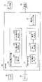
- FIG. 1 is a block diagram showing the configuration of the object detection device according to the first embodiment.
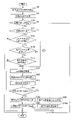
- FIG. 2 is a flow chart showing a process of determining whether or not an object is a floating object by the object detection device according to the first embodiment.
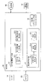
- FIG. 3 is a block diagram showing the configuration of an object detection device according to the first modification of the first embodiment.
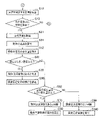
- FIG. 4 is a flowchart showing a process of determining whether or not an object is a floating object by the object detection device according to the first modification of the first embodiment.
- FIG. 5 is a conceptual diagram showing processing for determining an object as a floating object by the object detection device according to the first modification of the first embodiment.
- FIG. 6 is a conceptual diagram showing processing for determining that an object is not a floating object by the object detection device according to the first modification of the first embodiment.
- FIG. 7 is a block diagram showing the configuration of an object detection device according to the second modification of the first embodiment.
- FIG. 8 is a flowchart showing a process of determining whether or not an object is a floating object by the object detection device according to the second modification of the first embodiment.
- FIG. 9 is a block diagram showing the configuration of an object detection device according to the second embodiment.
- FIG. 10A is a flowchart showing a process of determining whether an object is a floating object by the object detection device according to the second embodiment.
- FIG. 10A is a flowchart showing a process of determining whether an object is a floating object by the object detection device according to the second embodiment.
- FIG. 10B is a flowchart showing a process of determining whether or not an object is a floating object by the object detection device according to the second embodiment
- FIG. 11 is a block diagram showing the configuration of an object detection device according to the third embodiment.
- FIG. 12A is a flowchart showing a process of determining whether an object is a floating object by the object detection device according to the third embodiment
- FIG. 12B is a flowchart showing a process of determining whether or not an object is a floating object by the object detection device according to the third embodiment
- FIG. 12C is a flowchart showing a process of determining whether an object is a floating object by the object detection device according to the third embodiment
- An object detection device is a device that detects an object in front of a vehicle and determines whether or not the object is a floating object.
- the object detection device includes a radar 10 , a camera 20 , a control section 30 and a storage section 40 .
- the radar 10 is mounted in the front bumper or front grill in front of the vehicle.
- the radar 10 is a sensor that radiates electromagnetic waves in front of the vehicle and detects objects in front of the vehicle based on reflected waves of the radiated electromagnetic waves.
- the radar 10 detects an object, measures the azimuth of the object, which is the position information of the object, and the distance from the own vehicle to the object, and calculates the position coordinates of the object based on the position of the own vehicle. Additionally, the radar 10 measures the velocity of the object in addition to this information.
- a radar is used as means for detecting an object, but a lidar (LiDER) may be used to detect an object in front of the vehicle.
- LiDER lidar
- the camera 20 is mounted in front of the interior of the vehicle.
- the camera 20 acquires a plurality of images in front of the vehicle by repeatedly capturing an image of the front of the vehicle at a predetermined cycle.
- the camera 20 forms an image of light rays from a subject on a light receiving plane of an imaging element by a lens, and obtains an optical image generated based on the contrast of light in the formed subject image.
- Optical images are images produced by light in the visible, infrared, or ultraviolet range.
- the camera 20 acquires a plurality of images by repeatedly imaging the front of the vehicle until the state in which no object is detected changes to the state in which an object is detected.
- the control unit 30 is a general-purpose microcomputer equipped with a CPU (central processing unit), memory, and input/output unit.
- a computer program for functioning as the control unit 30 is installed in the microcomputer.
- the microcomputer By executing the computer program, the microcomputer functions as a plurality of information processing circuits included in the control section 30 .
- an example of realizing a plurality of information processing circuits provided in the control unit 30 by software is shown. It is also possible to construct a processing circuit. Also, a plurality of information processing circuits may be configured by individual hardware.
- the storage unit 40 is composed of information storage devices including HDD (Hard Disk Drive) and SSD (Solid State Drive).
- the storage unit 40 stores a plurality of images of the front of the vehicle captured by the camera 20 in chronological order.
- the storage unit 40 stores at least an image captured when the object is not detected until the state in which the object is not detected changes to the state in which the object is detected. That is, when the state in which the object is not detected changes to the state in which the object is detected, the second image when the state changes to the state in which the object is detected (hereinafter also referred to as the second optical image) and a first image (hereinafter also referred to as a first optical image) in a state in which no object was detected one cycle or several cycles before.
- HDD Hard Disk Drive
- SSD Solid State Drive
- the storage unit 40 stores a plurality of past images captured at a predetermined cycle. Identify the image as a second optical image. Then, the storage unit 40 specifies, as the first optical image, the image in the state in which the object is not detected one cycle or several cycles before, and thus the image other than the first optical image and the second optical image is specified. Two or more images including images may be stored. In this embodiment, the storage unit 40 stores the images captured by the camera 20. If the memory provided in the control unit 30 can store these data, the memory provided in the control unit 30 can store these data. good too.
- control unit 30 and the storage unit 40 are mounted on the own vehicle. Note that the control unit 30 and the storage unit 40 may be mounted on the vehicle as one controller.
- control unit 30 a plurality of information processing circuits provided in the control unit 30 will be specifically described.
- the control unit 30 includes a floating object determination unit 31.
- the floating object determination unit 31 determines whether or not the object detected by the radar 10 is a floating object based on the optical image captured by the camera 20 .
- Floating matter is objects that float in the air, such as exhaust gas, water spray, and dust. In other words, suspended matter is an aggregate of minute particles that float.
- the floating object determination unit 31 is composed of a determination range determination unit 311 , a difference calculation unit 312 and a difference determination unit 313 .
- the determination range determination unit 311 When the determination range determination unit 311 detects that the state in which the object is not detected changes to the state in which the object is detected, the determination range determination unit 311 transmits the second optical image, which is the image captured when the object is detected, to the camera. 20 to determine the extent of the image to determine whether the object is a floating object. Processing executed by the determination range determination unit 311 will be specifically described below.
- the determination range determination unit 311 detects that the state in which no object has been detected has changed to the state in which an object has been detected.
- the information output from the radar 10 is, for example, a flag indicating whether or not an object has been detected.
- the radar 10 outputs values such as the azimuth of the object and the distance from the vehicle to the object, which are the position information of the object, as invalid values (values that must not be used for control). In this case, the determination range determination unit 311 may use these values.
- the determination range determining unit 311 detects a change in the value of the flag output from the radar 10 or the position information of the object, thereby detecting that the state in which the object has not been detected has changed to the state in which the object has been detected. be able to.
- the determination range determination unit 311 detects that the state in which the object is not detected changes to the state in which the object is detected, the determination range determination unit 311 outputs the second optical image captured when the object is detected to the camera. 20.
- the determination range determination unit 311 acquires the position information of the object from the radar 10 and selects a pixel area corresponding to the position of the object detected by the radar 10 from the second optical image.
- the radar 10 and the camera 20 are mounted on the vehicle and have a detection range or an imaging range in front of the vehicle. Therefore, the position coordinates of the object output by the radar 10 and the pixel positions of the image acquired by the camera 20 are synchronized in advance.
- the determination range determination unit 311 can select the pixel position of the image corresponding to the position of the object detected by the radar 10 .
- the determination range determination unit 311 sets the pixel area of the second optical image corresponding to the position of the object as the range of the image for determining whether the object is floating matter.
- the difference calculation unit 312 calculates the difference between the first optical image captured when the object is not detected and the second optical image captured when the object is detected. Specifically, the difference calculation unit 312 acquires the first optical image captured when the object is not detected from the storage unit 40, and the determination range determination unit 311 acquires the second optical image and the object if the object is a floating object. Obtain a pixel region corresponding to the position of the object, which is the range of the image to be determined. Then, the difference calculation unit 312 calculates the brightness, saturation, and hue of the first optical image and the second optical image at the same pixel position in the pixel region of the image for determining whether or not the object is floating matter. Calculate at least one difference. For example, when the image acquired by the camera 20 is a grayscale image, the difference calculator 312 calculates the difference in brightness. Moreover, when the image acquired by the camera 20 is a color image, all differences in brightness, saturation, and hue may be calculated.
- the difference determination unit 313 determines whether the difference between the first optical image and the second optical image calculated by the difference calculation unit 312 is less than the threshold difference.
- the difference between the first optical image and the second optical image when detecting floating matter such as exhaust gas, water spray, and dust (floating matter as an aggregate of microscopic particles floating) is the difference between the first optical image and the second optical image. is smaller than the difference when an object that is an obstacle to the vehicle is detected. Therefore, when the difference between the first optical image and the second optical image is less than the threshold difference, the difference determination unit 313 determines that the object is a floating object. If the difference between the first optical image and the second optical image is greater than or equal to the threshold difference, the difference determination unit 313 determines that the object is not floating matter.
- the threshold difference and the threshold ratio can be determined by experimentally acquiring in advance the luminance difference and the ratio of pixels whose luminance difference is less than the threshold difference when floating matter is generated. For example, when the optical image acquired by the camera 20 is grayscale and the brightness is processed with 8-bit data, the brightness threshold difference is hexadecimal 10 (0x10) and the threshold ratio is 70%.
- the difference determination unit 313 calculates the average value of the differences in the pixel region for determining whether or not the object is a floating object, and if the average value of the differences is less than the threshold average value, determines that the object is a floating object. can be determined.
- the vehicle control unit 50 controls the own vehicle based on information about the surroundings of the own vehicle acquired by sensors mounted on the own vehicle including the radar 10 and the camera 20, and map data stored in advance in the storage unit 40. , driving assistance and autonomous driving.
- the vehicle control unit 50 detects an object on the travel route of the own vehicle and determines that the distance to the detected object is likely to be less than a predetermined distance, the detected object is a floating object. Based on the result of whether or not there is an object, it is determined whether or not to control the host vehicle so as to avoid a state in which the distance to the object is less than a predetermined distance.
- the vehicle control unit 50 When the vehicle control unit 50 detects an object in front of the vehicle and determines that the detected object is not a floating object, the vehicle control unit 50 executes control to avoid a state in which the distance to the object is less than a predetermined distance. Specifically, the vehicle control unit 50 prohibits start control during start standby, and executes deceleration control or avoidance control for steering and driving the steered wheels during running to increase the distance from the object to a predetermined distance or more. Control the vehicle to keep
- the vehicle control unit 50 When the vehicle control unit 50 detects an object in front of the vehicle and determines that the detected object is a floating object, the vehicle control unit 50 prohibits execution of control to avoid a state in which the distance to the object is less than a predetermined distance. do.
- step S0 the radar 10 emits electromagnetic waves in front of the own vehicle and detects objects based on the reflected waves of the electromagnetic waves. Specifically, the presence or absence of an object and the position of the object are detected.
- step S5 the camera 20 acquires a plurality of images in front of the vehicle by repeatedly capturing images of the front of the vehicle at predetermined intervals until the state in which the object is not detected changes to the state in which the object is detected.
- the storage unit 40 stores a plurality of images of the front of the vehicle captured by the camera 20 in chronological order.
- step S10 the determination range determining unit 311 detects that the state in which no object has been detected has changed to the state in which an object has been detected, based on the information output from the radar 10. If determination range determination unit 311 detects that the state in which no object has been detected has changed to the state in which an object has been detected (YES in step S10), the process proceeds to step S20. If determination range determination unit 311 does not detect a change from the state in which no object is detected to the state in which object is detected (NO in step S10), the process ends.
- the difference calculation unit 312 acquires from the storage unit 40 the first optical image captured when no object is detected.
- the determination range determination unit 311 acquires from the camera 20 the second optical image captured while the object is being detected.
- the determination range determination unit 311 acquires the position information of the object from the radar 10, and selects a pixel area corresponding to the position of the object detected by the radar 10 from the second optical image.
- the determination range determination unit 311 sets the pixel area of the second optical image corresponding to the position of the detected object as the image range for determining whether or not the object is a floating object.
- the difference calculation unit 312 acquires the second optical image from the determination range determination unit 311 and the range of the image for determining whether or not the object is a floating object.
- the difference between the first optical image and the second optical image at the same pixel position is calculated in the pixel region of the image for which the determination is made.
- step S60 when the difference determination unit 313 determines that the difference between the first optical image and the second optical image is less than the threshold difference (YES in step S60), the process proceeds to step S70, Determine that the object is a floating object.
- step S90 the vehicle control unit 50 continues to control the own vehicle. That is, the vehicle control unit 50 prohibits execution of control for avoiding a state in which the distance to the object is less than the predetermined distance.
- step S60 when the difference determination unit 313 determines that the difference in brightness between the first optical image and the second optical image is equal to or greater than the threshold difference (NO in step S60), the process proceeds to step S80. , determine that the object is not a floating object.
- the vehicle control unit 50 controls the own vehicle to avoid a state in which the distance to the object is less than a predetermined distance.
- the object detection device emits electromagnetic waves in front of the vehicle and detects objects in front of the vehicle based on the reflected waves of the emitted electromagnetic waves.
- the object detection device obtains an image by capturing an image of the area in front of the vehicle, and determines whether or not the object is a floating object based on the image when the state in which the object is not detected changes to the state in which the object is detected. to judge. That is, detection of an object is performed by reflected waves of electromagnetic waves, and determination as to whether or not the detected object is a floating object is performed by an image. As a result, the object detection device can more accurately detect an object and determine whether or not the detected object is a floating object.
- the object detection device acquires a first optical image by imaging the front of the vehicle when no object is detected, and acquires a second optical image by imaging the front of the vehicle when the object is detected. .
- the object detection device calculates the difference between the first optical image and the second optical image, and determines that the object is a floating object when the difference is less than the threshold difference. Thereby, the object detection device can determine whether or not the object is a floating substance when the object is detected, and can more quickly determine whether or not the object is a floating substance.
- the preceding vehicle information generation unit 32 determines whether the detected object is the preceding vehicle in front of the own vehicle, and if the object is the preceding vehicle, measures the behavior of the preceding vehicle. Then, the preceding vehicle information generator 32 determines whether or not the behavior of the preceding vehicle is within the threshold behavior.
- the preceding vehicle information generating section 32 is composed of a preceding vehicle detecting section 321 and a preceding vehicle behavior determining section 322 .
- the preceding vehicle detection unit 321 determines whether the detected object is the preceding vehicle. Specifically, the preceding vehicle detection unit 321 acquires the distance to each position of the object measured by the radar 10, and identifies the shape and size of the object from the distance to each position of the object. The preceding vehicle detection unit 321 determines whether the object is the preceding vehicle based on the shape and size of the object. Specifically, the preceding vehicle detection unit 321 calculates the matching rate between the shape and size of the identified object and the shape and size of the vehicle stored in advance in the storage unit 40, and the matching rate is higher than the threshold matching rate. is also high, it is determined that the object is the preceding vehicle.
- the preceding vehicle detection unit 321 determines whether or not the object is the preceding vehicle based on the distance to each position of the object measured by the radar 10. It may be determined whether or not the object is the preceding vehicle based on the obtained image. It should be noted that it is possible to determine whether or not the object is the preceding vehicle by image analysis using a known image recognition technique.
- the preceding vehicle behavior determining unit 322 acquires the speed of the preceding vehicle from the change in the distance to the preceding vehicle over time, that is, the speed relative to the own vehicle and the speed of the own vehicle. and determine the behavior of the preceding vehicle.
- the preceding vehicle behavior determination unit 322 detects that the preceding vehicle has started from a stopped state (less than 0.5 km/h) from the change in the speed of the preceding vehicle, and detects the threshold value after the preceding vehicle has started. Determine whether time has passed. For example, the threshold time is 3 seconds.
- the preceding vehicle behavior determination unit 322 determines whether the speed of the preceding vehicle is less than the threshold speed.
- the threshold speed is 10 km/h.
- a preceding vehicle behavior determination unit 322 detects that the preceding vehicle has started from a stopped state, and if the threshold time has not elapsed since the preceding vehicle started moving, it determines that the behavior of the preceding vehicle is within the threshold behavior. to decide. Alternatively, when the speed of the preceding vehicle is less than the threshold speed, the preceding vehicle behavior determination unit 322 determines that the behavior of the preceding vehicle is within the threshold behavior.
- the determination range determination unit 311 determines the second position corresponding to the position of the object.
- a pixel area of the optical image is set as an image range for determining whether or not the object is a floating object.
- the floating object tracking unit 33 tracks objects determined to be floating objects by the floating object determination unit 31 . Specifically, the floating object tracking unit 33 sets an object determined as a floating object by the difference determination unit 313 as a tracking target, and tracks the floating object using an image acquired by the camera 20 or the radar 10 . Note that the floating object tracking unit 33 may track an object using both the image acquired by the camera 20 and the radar 10 . The floating object tracking unit 33 outputs the object being tracked to the floating object determination unit 31 .
- step S11 the preceding vehicle detection unit 321 acquires the distance to each position of the object measured by the radar 10, and identifies the shape and size of the object from the distance to each position of the object.
- the preceding vehicle detection unit 321 determines whether the object is the preceding vehicle based on the shape and size of the object.
- the process proceeds to step S12. If the preceding vehicle detection unit 321 determines that the object is not the preceding vehicle (NO in step S11), the process proceeds to step S20.
- step S12 the preceding vehicle behavior determination unit 322 acquires the speed of the preceding vehicle from the radar 10 and determines the behavior of the preceding vehicle. Specifically, the preceding vehicle behavior determination unit 322 detects that the preceding vehicle has started from a stopped state, and if the threshold time has not elapsed since the preceding vehicle started moving, or if the speed of the preceding vehicle is If the speed is less than the threshold, it is determined that the behavior of the preceding vehicle is within the threshold behavior. When the preceding vehicle behavior determination unit 322 determines that the behavior of the preceding vehicle is within the threshold behavior (YES in step S12), the process proceeds to step S13. If the preceding vehicle behavior determination unit 322 determines that the behavior of the preceding vehicle is not within the threshold behavior (NO in step S12), the process ends.
- step S13 when the determination range determining unit 311 detects that the state in which no object is detected behind the preceding vehicle changes to the state in which an object is detected (YES in step S13), the process proceeds to step S20. move on.
- determination range determination unit 311 has not detected a change from the state in which an object is not detected to the state in which an object is detected behind the preceding vehicle (NO in step S13), the process ends.
- the object detection device detects a preceding vehicle, and determines whether the object detected behind the preceding vehicle is a floating object. A specific description will be given of the processing for determining whether or not.
- the preceding vehicle detection unit 321 acquires the distance to each position of the object 1 measured by the radar 10, Object 1 is determined to be the preceding vehicle based on the shape and size of the object.
- the preceding vehicle behavior determination unit 322 acquires the speed of the preceding vehicle from the radar 10 and determines the behavior of the preceding vehicle. At the time when the first optical image a and the second optical image b are acquired by the camera 20, the speed of the preceding vehicle is less than the threshold speed. Therefore, the preceding vehicle behavior determination unit 322 determines that the behavior of the preceding vehicle is within the threshold behavior.
- the determination range determining unit 311 determines whether the object 2 is detected from the state in which the object 2 is not detected. Detects a change to the detected state.
- the difference calculation unit 312 acquires from the storage unit 40 the first optical image a captured when the object 2 behind the preceding vehicle is not detected, and the determination range determination unit 311 calculates the object 2 behind the preceding vehicle.
- a second optical image b captured when is detected is acquired from the camera 20 .
- the determination range determining unit 311 sets the pixel area of the second optical image b corresponding to the position of the object 2 detected by the radar 10 as the image range 3 for determining whether the object 2 is a floating object. do.
- the difference calculation unit 312 acquires the second optical image b and the range 3 of the image for determining whether or not the object 2 is a floating object from the determination range determination unit 311, and determines whether or not the object 2 is a floating object.
- the difference between the first optical image a and the second optical image b at the same pixel position is calculated in the range 3 of the image for which the determination is made.
- the difference between the first optical image a and the second optical image b is less than the threshold difference. Therefore, the difference determination unit 313 determines that the object 2 is a floating object.
- the determination range determination unit 311 sets the pixel area of the second optical image d corresponding to the position of the object 2 detected by the radar 10 as the image range 3 for determining whether the object 2 is a floating object. do.
- the difference calculation unit 312 acquires the second optical image d and the image range 3 for determining whether the object 2 is a floating substance from the determination range determination unit 311, and determines whether the object 2 is a floating substance.
- the difference between the first optical image c and the second optical image d at the same pixel position is calculated in the range 3 of the image for which the determination is made.
- the difference between the first optical image c and the second optical image d is equal to or greater than the threshold difference. Therefore, the difference determination unit 313 determines that the object 2 is not floating.
- the object detection device detects the object as a floating object until a threshold time elapses after the preceding vehicle starts moving. determine whether there is Vehicles generate more floating matter such as exhaust gas, water spray and dust when starting. Therefore, the object detection device determines whether or not the detected object is a floating object until a predetermined time has elapsed since the preceding vehicle started moving. Objects such as exhaust gas, splashes of water, and dust can be determined as floating objects.
- the object detection device determines whether the object is a floating object when the object is located behind the preceding vehicle in front of the vehicle and the speed of the preceding vehicle is less than the threshold speed. If the preceding vehicle is traveling below the threshold speed, there is a high possibility that the preceding vehicle will accelerate thereafter. Vehicles produce more floating matter such as exhaust fumes, water spray and dust as they accelerate. Therefore, when the speed of the preceding vehicle is less than the threshold speed, the object detection device determines whether or not the detected object is a floating object. Objects such as exhaust gas, splashes of water, and dust can be determined as floating objects.
- the object detection device can reduce the process of re-determining whether or not an object once determined to be a floating matter is a floating matter. As a result, the object detection device can reduce the load of processing for determining whether or not the detected object is a floating object.
- the preceding vehicle exhaust pipe detection unit 323 detects the exhaust pipe of the preceding vehicle detected by the preceding vehicle detection unit 321 from the image acquired by the camera 20 . Specifically, the preceding vehicle exhaust pipe detection unit 323 detects the position of the exhaust pipe of the vehicle, which is stored in advance in the storage unit 40, from the pixel position of the image corresponding to the height from 1/5 of the total height of the preceding vehicle to the ground. A part with a similar shape is detected and identified as the exhaust pipe of the preceding vehicle.
- the judgment range determination unit 311 sets the image range for judging whether or not the object is a floating object to the position of the exhaust pipe of the preceding vehicle. set accordingly. Specifically, the determination range determination unit 311 acquires an image from the camera 20, and determines that the object is a floating object in a pixel region of a predetermined range above the detected exhaust pipe in the pixel region of the image corresponding to the preceding vehicle. It is set as the range of the image for judging whether or not it is.
- the predetermined range of pixel regions is a pixel region of a range corresponding to a predetermined distance range with respect to the exhaust pipe.
- the predetermined distance range is, for example, 1 meter.
- the determination range determining unit 311 determines the pixel region of the second image corresponding to the position of the detected object as being a floating object. Set as the range of the image to determine whether or not there is.
- step S14 and step S15 are further provided, and step S40 is deleted in the processing after step S15. Therefore, only the difference will be described, and description of other common processes will be omitted.
- step S ⁇ b>14 the preceding vehicle exhaust pipe detection unit 323 detects the exhaust pipe of the preceding vehicle from the image acquired by the camera 20 . If the preceding vehicle exhaust pipe detection unit 323 detects the exhaust pipe of the preceding vehicle (YES in step S14), the process proceeds to step S15. If the preceding vehicle exhaust pipe detector 323 has not detected the exhaust pipe of the preceding vehicle (NO in step S14), the process proceeds to step S13.
- step S15 the judgment range determination unit 311 sets the image range for judging whether or not the object is a floating object according to the position of the exhaust pipe of the preceding vehicle. Specifically, the determination range determination unit 311 acquires an image from the camera 20, and determines that the object is a floating object in a pixel region of a predetermined range above the detected exhaust pipe in the pixel region of the image corresponding to the preceding vehicle. It is set as the range of the image for judging whether or not it is. After setting the range of the image, the process proceeds to step S13.
- step S13 the determination range determination unit 311 determines that the exhaust pipe of the preceding vehicle has been detected, and the state in which the object has not been detected has changed to the state in which the object has been detected in the pixel region within a predetermined range above the exhaust pipe. is detected (YES in step S13), the process proceeds to step S20. If the determination range determining unit 311 has not detected a change from a state in which an object is not detected to a state in which an object is detected in a pixel region within a predetermined range above the exhaust pipe (NO in step S13), End the process.
- the object detection device detects whether the object is a floating object or not. Set according to the position of the tube. As a result, the object detection device can more accurately determine the exhaust gas generated by the preceding vehicle as floating matter.
- the camera 20 captures an image of the front of the vehicle, measures the brightness of the infrared rays, and acquires an infrared image showing the brightness of the infrared rays.
- the determination range determination unit 311 determines a predetermined range above the detected exhaust pipe in the pixel region of the infrared image corresponding to the preceding vehicle. is set as the range of the image for judging whether or not the object is a floating object.
- the determination range determining unit 311 determines that the pixel area of the infrared image corresponding to the position of the detected object is a floating object. Set as the range of the image to determine whether or not.
- the temperature calculation unit 314 calculates the temperature of the object based on the infrared luminance at the position corresponding to the object in the infrared image. Specifically, when the state behind the preceding vehicle changes from a state in which an object is not detected to a state in which an object is detected, the temperature calculation unit 314 acquires an infrared image captured when the object was detected. Then, the temperature of the object in the range of the image for judging whether or not the object is a floating substance is calculated from the brightness of the infrared image at the corresponding position.
- the temperature calculation unit 314 calculates the amount of change in the temperature of the object based on the infrared luminance at the position corresponding to the object in the infrared image. Specifically, the temperature calculation unit 314 detects the exhaust pipe of the preceding vehicle, and determines whether or not the object is a floating object. , the amount of change in temperature of the object in the range of the image is calculated from the amount of change in brightness of the infrared image at the corresponding position.
- the temperature calculation unit 314 can calculate the amount of change in temperature from the amount of change in luminance of the infrared image when the state in which no object is detected changes to the state in which an object is detected.
- the temperature calculator 314 may calculate the amount of change in brightness of the infrared image instead of the amount of change in temperature.
- the temperature determination unit 315 determines that the object is It is determined to be floating matter.
- the threshold temperature is, for example, 50°C.
- the temperature determination unit 315 determines whether the temperature of the object in the range of the image in which the exhaust pipe of the preceding vehicle is detected and whether or not the object is floating is less than the threshold temperature. is greater than or equal to the threshold change amount, it is determined that the object is a floating object.
- the threshold temperature is, for example, 50.degree. C.
- the threshold change amount is, for example, 20.degree.
- the temperature determination unit 315 sets a higher threshold temperature as the outside air temperature increases. Specifically, the temperature determination unit 315 changes the threshold temperature within the range of the temperature of the exhaust gas obtained in advance by experiments or the like. For example, the threshold temperature is set to 50°C when the outside air temperature is 25°C, and the threshold temperature is set higher by 1°C each time the outside air temperature rises by 1°C.
- step S31 the determination range determination unit 311 acquires from the camera 20 an infrared image captured while the radar 10 is detecting the object.
- the temperature calculation unit 314 calculates the temperature of the detected object based on the infrared luminance at the position corresponding to the object in the infrared image. Specifically, the temperature calculation unit 314 acquires the image range for determining whether or not the object is a floating object from the determination range determination unit 311, and obtains from the infrared image captured when the object is detected. Calculate the temperature of the object in the range of the infrared image to determine whether the object is a floating object.
- the temperature calculation unit 314 calculates the amount of change in the temperature of the detected object based on the infrared luminance at the position corresponding to the object in the infrared image. Specifically, the temperature calculation unit 314 detects the exhaust pipe of the preceding vehicle and determines whether the object is a floating object or not in the range of the image in which the object is not detected, and the object is detected. When the state changes, the amount of change in temperature of the object within the range of the image is calculated from the amount of change in brightness of the infrared image at the corresponding position.
- the temperature calculation unit 314 may calculate the amount of change in brightness of the infrared image instead of the amount of change in temperature.
- the determination of whether the amount of change in temperature is greater than or equal to the threshold change in step S62 described later is performed when the amount of change in brightness of the infrared image is greater than or equal to the threshold change in brightness. or not.
- step S61 when the temperature determination unit 315 determines that the temperature of the object is equal to or higher than the threshold temperature (YES in step S61), the process proceeds to step S70.
- step S13 When the exhaust pipe of the preceding vehicle is detected (YES in step S13) and the temperature determination unit 315 determines in step S61 that the temperature of the object is lower than the threshold temperature (NO in step S61), the process proceeds to step S62. proceed to
- step S62 when the temperature determination unit 315 determines that the amount of change in the temperature of the object is equal to or greater than the threshold amount of change (YES in step S62), the process proceeds to step S70.
- step S62 when temperature determination unit 315 determines that the amount of change in the temperature of the object is less than the threshold amount of change (NO in step S62), the process proceeds to step S80.
- the object detection device captures an infrared image in front of the vehicle, and calculates the temperature of the object based on the brightness of the infrared light at the position corresponding to the object in the infrared image.
- the object detection device determines that the object is a floating object when the temperature of the object is equal to or higher than the threshold temperature.
- the object detection device can determine whether or not the object is a floating substance based on the temperature of the object, and can more accurately determine that the exhaust gas of a vehicle having a temperature equal to or higher than the threshold temperature is a floating substance. can be done.
- the object detection device When the object detection device detects the exhaust pipe of the preceding vehicle, it sets the range of the infrared image for judging whether the object is a floating object according to the position of the exhaust pipe of the preceding vehicle.
- the object detection device calculates the amount of change in temperature of an object detected in the range of the infrared image for determining whether or not the object is a floating object from the amount of change in brightness of the infrared image at the corresponding position, and detects If the amount of change in temperature of the detected object is greater than or equal to the threshold change amount, the object is determined to be floating.
- the preceding vehicle If the amount of change in the temperature of the object detected in the range of the infrared image used to determine whether the object is floating matter is greater than or equal to the threshold change amount, the preceding vehicle emits the exhaust gas that is floating matter. likely to be. Therefore, it is possible to more accurately determine the exhaust gas emitted by the preceding vehicle as floating matter.
- the object detection device sets the threshold temperature higher as the outside air temperature rises.
- the temperature of the exhaust gas at the outlet of the exhaust pipe is higher than the surface temperature of the human body.
- the higher the outside air temperature the higher the surface temperature of the human body. Therefore, the higher the outside air temperature, the smaller the difference between the surface temperature of the human body and the temperature of the exhaust gas. Therefore, by setting the threshold temperature higher as the outside air temperature increases, the object detection apparatus can prevent erroneous determination of a human body as a floating object, and can more accurately determine an object as a floating object. can.
- step S61 if it is determined in step S61 that the temperature of the object is lower than the threshold temperature, the process proceeds to step S62.
- step S62 if it is determined in step S61 that the temperature of the object is lower than the threshold temperature, the process proceeds to step S62.
- the determination of whether the temperature of the object is equal to or higher than the threshold temperature in step S61 is omitted, and the object is determined to be a floating substance based only on the determination of whether the temperature change amount is equal to or higher than the threshold change amount in step S62. It may be determined whether or not
- the determination of whether or not the amount of change in temperature is equal to or greater than the threshold change amount in step S62 is based on the change in luminance of the infrared image. It may be used as a judgment of whether or not.
- step S61 If the temperature of the object is equal to or higher than the threshold temperature in step S61, it is determined that the object is floating, and if the temperature of the object is lower than the threshold temperature in step S61, the process after step S62 is omitted. , it may be determined that it is not a floating substance.
- step S61 if the temperature of the object is less than the threshold temperature in step S61, it is determined whether or not the amount of change in the temperature of the object is equal to or greater than the threshold change in step S62.
- the reason for determining whether or not is that the purpose is to improve the determination accuracy of floating matter by combining the processing of step S61 and the processing of step S62, and either the processing of step S61 or step S62 It is possible to determine whether or not the object is floating matter by itself.
- the object detection method according to the third embodiment has a configuration in which the processing of the second modification of the first embodiment and the processing of the second embodiment are connected at the conditional branching of step S60. Therefore, only the processing in step S60 will be described, and description of other common processing will be omitted.
- step S60 when the difference determination unit 313 determines that the difference in brightness between the first optical image and the second optical image is less than the threshold difference (YES in step S60), the process proceeds to step S70. , determine that the object is a floating object.
- step S60 when the difference determination unit 313 determines that the difference in luminance between the first optical image and the second optical image is equal to or greater than the threshold difference (NO in step S60), the process proceeds to step S11. .
- the object detection device acquires an optical image and an infrared image
- the difference in brightness between the first optical image and the second optical image is equal to or greater than the threshold difference
- the temperature of the object is equal to or greater than the threshold temperature
- the difference in luminance between the first optical image and the second optical image is equal to or greater than the threshold difference
- the object is determined to be a floating object based on the temperature of the object calculated based on the infrared image. It is possible to judge whether or not That is, in a state where the vehicle exhaust gas, which is floating matter, remains, it is possible to determine that the vehicle exhaust gas is floating matter based on the temperature.
Landscapes
- Engineering & Computer Science (AREA)
- Radar, Positioning & Navigation (AREA)
- Remote Sensing (AREA)
- Physics & Mathematics (AREA)
- General Physics & Mathematics (AREA)
- Computer Networks & Wireless Communication (AREA)
- Multimedia (AREA)
- Theoretical Computer Science (AREA)
- Spectroscopy & Molecular Physics (AREA)
- Electromagnetism (AREA)
- Traffic Control Systems (AREA)
Abstract
Description
[物体検出装置の構成]
図1を参照して、第1実施形態に係る物体検出装置の構成を説明する。物体検出装置は、自車両前方の物体を検出し、当該物体が浮遊物であるか否かを判断する装置である。物体検出装置は、レーダ10、カメラ20、制御部30、記憶部40を備えている。
次に、図2を参照して図1の物体検出装置が、検出した物体が浮遊物であるか否かを判断する方法の一例を説明する。図2のフローチャートに示す物体検出装置の動作は、自車両のイグニッションスイッチ又はパワースイッチがONとなると同時に開始され、イグニッションスイッチ又はパワースイッチがOFFとなった時点で処理を終了する。
[物体検出装置の構成]
図3を参照して、第1実施形態の第1変形例に係る物体検出装置の構成を説明する。第1実施形態との相違点は、制御部30が先行車情報生成部32、浮遊物トラッキング部33をさらに備える点、及び、判定範囲決定部311の一部処理である。よって、当該相違点についてのみ説明し、その他共通する構成については説明を省略する。
次に、図4を参照して図3の物体検出装置が、検出した物体が浮遊物であるか否かを判断する方法の一例を説明する。第1実施形態との相違点は、ステップS11からステップS13をさらに備える点である。よって当該相違点についてのみ説明し、その他共通する処理については説明を省略する。
[物体検出装置の構成]
図7を参照して、第1実施形態の第2変形例に係る物体検出装置の構成を説明する。第1実施形態の第1変形例との相違点は、先行車情報生成部32が先行車排気管検出部323をさらに備える点、及び、判定範囲決定部311の一部処理である。よって、当該相違点についてのみ説明し、その他共通する構成については説明を省略する。
次に、図8を参照して図7の物体検出装置が、検出した物体が浮遊物であるか否かを判断する方法の一例を説明する。第1実施形態の第1変形例との相違点は、ステップS14、ステップS15をさらに備え、ステップS15以降の処理においてステップS40が削除されている点である。よって当該相違点についてのみ説明し、その他共通する処理については説明を省略する。
[物体検出装置の構成]
図9を参照して、第2実施形態に係る物体検出装置の構成を説明する。第1実施形態の第2変形例との相違点は、カメラ20の仕様、判定範囲決定部311の一部処理、差分算出部312、差分判定部313に代えて、温度算出部314、温度判定部315を備える点である。よって、当該相違点についてのみ説明し、その他共通する構成については説明を省略する。
次に、図10A、10Bを参照して図9の物体検出装置が、検出した物体が浮遊物であるか否かを判断する方法の一例を説明する。第1実施形態の第2変形例との相違点は、ステップS20、ステップS30、ステップS50に処理に代えて、ステップS31、ステップS51、ステップS52、ステップS61、ステップS62の処理を行う点である。よって当該相違点についてのみ説明し、その他共通する処理については説明を省略する。
[物体検出装置の構成]
図11を参照して、第3実施形態に係る物体検出装置の構成を説明する。第2実施形態との相違点は、差分算出部312、差分判定部313をさらに備える点である。なお、差分算出部312、差分判定部313は第1実施形態と共通であり、説明を省略する。
次に、図12を参照して図11の物体検出装置が、検出した物体が浮遊物であるか否かを判断する方法の一例を説明する。第3実施形態に係る物体検出方法は、ステップS60の条件分岐にて第1実施形態の第2変形例と第2実施形態との処理が接続される構成となっている。よって、ステップS60での処理についてのみ説明し、その他共通する処理については説明を省略する。
20 カメラ
30 制御部
31 浮遊物判定部
311 判定範囲決定部
312 差分算出部
313 差分判定部
314 温度算出部
315 温度判定部
32 先行車情報生成部
321 先行車検出部
322 先行車挙動判定部
323 先行車排気管検出部
33 浮遊物トラッキング部
Claims (12)
- 自車両前方に電磁波を照射し、
前記電磁波の反射波に基づいて前記自車両前方の物体を検出し、
前記自車両前方を撮像して画像を取得し、
前記物体が検出されていない状態から、前記物体が検出された状態へ変化した場合、前記画像に基づいて前記物体が浮遊物であるか否かを判断する
ことを特徴とする物体検出方法。 - 前記画像は、光学画像であって、
前記物体が検出されていない時に前記自車両前方を撮像して第1の画像を取得し、
前記物体が検出されている時に前記自車両前方を撮像して第2の画像を取得し、
前記第1の画像と前記第2の画像との差分を算出し、
前記差分がしきい差分未満である場合、前記物体が前記浮遊物であると判定する
ことを特徴とする請求項1に記載の物体検出方法。 - 前記画像は、赤外画像であって、
前記赤外画像の前記物体に対応する位置の赤外線の輝度に基づいて、前記物体の温度を算出し、
前記物体の温度がしきい温度以上である場合、前記物体が前記浮遊物であると判定する
ことを特徴とする請求項1に記載の物体検出方法。 - 前記画像は、赤外画像であって、
前記赤外画像の前記物体に対応する位置の赤外線の輝度の変化に基づいて、前記物体の温度の変化量を算出し、
前記物体の温度の変化量がしきい変化量以上である場合、前記物体が前記浮遊物であると判定する
ことを特徴とする請求項1に記載の物体検出方法。 - 前記物体の温度がしきい温度未満である場合、前記物体の温度の変化量を算出し、
前記物体の温度の変化量が前記しきい変化量以上である場合、前記物体が前記浮遊物であると判定する
ことを特徴とする請求項4に記載の物体検出方法。 - 前記画像は、前記光学画像又は前記赤外画像であって、
前記第1の画像と前記第2の画像との差分がしきい差分以上であり、前記物体の温度がしきい温度以上である場合、前記物体が前記浮遊物であると判定する
ことを特徴とする請求項2に記載の物体検出方法。 - 前記物体は、前記自車両前方の先行車よりも後方に位置し、
前記先行車が停車状態から発進した場合、前記先行車が発進してからしきい時間が経過するまで、前記物体が浮遊物であるか否かを判断する
ことを特徴とする請求項1から6のいずれか一項に記載の物体検出方法。 - 前記物体は、前記自車両前方の先行車よりも後方に位置し、
前記先行車の速度がしきい速度未満である場合、前記物体が浮遊物であるか否かを判断する
ことを特徴とする請求項1から7のいずれか一項に記載の物体検出方法。 - 前記物体は、前記自車両前方の先行車よりも後方に位置し、
前記画像から前記先行車の排気管を検出した場合、前記物体が浮遊物であるか否かを判断する前記画像の範囲を前記先行車の前記排気管の位置に応じて設定する
ことを特徴とする請求項1から8のいずれか一項に記載の物体検出方法。 - 前記しきい温度は、外気温が高いほど高く設定する
ことを特徴とする請求項3、5、6のいずれか一項に記載の物体検出方法。 - 前記浮遊物をトラッキングする
ことを特徴する請求項1から9のいずれか一項に記載の物体検出方法。 - 自車両前方に電磁波を照射し、前記電磁波の反射波に基づいて前記自車両前方の物体を検出するセンサと、
前記自車両前方を撮像して画像を取得するカメラと、
制御部と、を備え、
前記制御部は、前記物体が検出されていない状態から、前記物体が検出された状態へ変化した場合、前記画像に基づいて前記物体が浮遊物であるか否かを判断する
ことを特徴とする物体検出装置。
Priority Applications (5)
| Application Number | Priority Date | Filing Date | Title |
|---|---|---|---|
| JP2023503517A JP7601201B2 (ja) | 2021-03-03 | 2021-03-03 | 物体検出方法及び物体検出装置 |
| CN202180095095.8A CN117121075A (zh) | 2021-03-03 | 2021-03-03 | 物体检测方法以及物体检测装置 |
| US18/280,022 US12181567B2 (en) | 2021-03-03 | 2021-03-03 | Object detection method and object detecting device |
| PCT/IB2021/000123 WO2022185085A1 (ja) | 2021-03-03 | 2021-03-03 | 物体検出方法及び物体検出装置 |
| EP21928380.1A EP4303850A4 (en) | 2021-03-03 | 2021-03-03 | Object detection method and object detection device |
Applications Claiming Priority (1)
| Application Number | Priority Date | Filing Date | Title |
|---|---|---|---|
| PCT/IB2021/000123 WO2022185085A1 (ja) | 2021-03-03 | 2021-03-03 | 物体検出方法及び物体検出装置 |
Publications (1)
| Publication Number | Publication Date |
|---|---|
| WO2022185085A1 true WO2022185085A1 (ja) | 2022-09-09 |
Family
ID=83154780
Family Applications (1)
| Application Number | Title | Priority Date | Filing Date |
|---|---|---|---|
| PCT/IB2021/000123 WO2022185085A1 (ja) | 2021-03-03 | 2021-03-03 | 物体検出方法及び物体検出装置 |
Country Status (5)
| Country | Link |
|---|---|
| US (1) | US12181567B2 (ja) |
| EP (1) | EP4303850A4 (ja) |
| JP (1) | JP7601201B2 (ja) |
| CN (1) | CN117121075A (ja) |
| WO (1) | WO2022185085A1 (ja) |
Cited By (1)
| Publication number | Priority date | Publication date | Assignee | Title |
|---|---|---|---|---|
| CN116021983A (zh) * | 2022-12-14 | 2023-04-28 | 深圳禄华科技有限公司 | 一种基于汽车热量管理的进风控制方法、系统、设备及介质 |
Citations (6)
| Publication number | Priority date | Publication date | Assignee | Title |
|---|---|---|---|---|
| JP2009110168A (ja) * | 2007-10-29 | 2009-05-21 | Fuji Heavy Ind Ltd | 物体検出装置および接触回避システム |
| JP2013206328A (ja) * | 2012-03-29 | 2013-10-07 | Fuji Heavy Ind Ltd | 物体検出装置 |
| JP2013203337A (ja) * | 2012-03-29 | 2013-10-07 | Fuji Heavy Ind Ltd | 運転支援装置 |
| JP2014093028A (ja) | 2012-11-06 | 2014-05-19 | Denso Corp | 監視装置 |
| JP2014518412A (ja) * | 2011-06-17 | 2014-07-28 | ローベルト ボッシュ ゲゼルシャフト ミット ベシュレンクテル ハフツング | 車両の周辺区域の気象条件を認識する方法および制御装置 |
| JP2019105648A (ja) * | 2013-04-11 | 2019-06-27 | ウェイモ エルエルシー | 車載センサを用いて気象状態を検出する方法及びシステム |
Family Cites Families (23)
| Publication number | Priority date | Publication date | Assignee | Title |
|---|---|---|---|---|
| US5202692A (en) * | 1986-06-16 | 1993-04-13 | Millitech Corporation | Millimeter wave imaging sensors, sources and systems |
| US5563982A (en) * | 1991-01-31 | 1996-10-08 | Ail Systems, Inc. | Apparatus and method for detection of molecular vapors in an atmospheric region |
| CN1258679C (zh) * | 2001-10-08 | 2006-06-07 | 赵桂林 | 对汽车尾气进行实时检测用的红外激光检测系统和方法 |
| JP4482599B2 (ja) * | 2008-10-24 | 2010-06-16 | 本田技研工業株式会社 | 車両の周辺監視装置 |
| US8102306B2 (en) * | 2010-05-13 | 2012-01-24 | The United States Of America As Represented By The Secretary Of The Navy | Active-radar-assisted passive composite imagery for aiding navigation or detecting threats |
| JP2012243049A (ja) * | 2011-05-19 | 2012-12-10 | Fuji Heavy Ind Ltd | 環境認識装置および環境認識方法 |
| JP5615862B2 (ja) | 2012-03-07 | 2014-10-29 | クラリオン株式会社 | 車両周囲監視装置 |
| JP2014024427A (ja) | 2012-07-26 | 2014-02-06 | Nissan Motor Co Ltd | 排気ガス検出装置及び排気ガス検出方法 |
| JP6031908B2 (ja) * | 2012-09-14 | 2016-11-24 | オムロン株式会社 | 画像処理装置、オブジェクト検出方法、およびオブジェクト検出プログラム |
| WO2014113457A1 (en) * | 2013-01-15 | 2014-07-24 | Gentex Corporation | Imaging system and method for detecting fog conditions |
| US9025140B2 (en) | 2013-05-07 | 2015-05-05 | Google Inc. | Methods and systems for detecting weather conditions including sunlight using vehicle onboard sensors |
| US9632210B2 (en) | 2013-05-07 | 2017-04-25 | Google Inc. | Methods and systems for detecting weather conditions using vehicle onboard sensors |
| US8983705B2 (en) | 2013-04-30 | 2015-03-17 | Google Inc. | Methods and systems for detecting weather conditions including fog using vehicle onboard sensors |
| US9207323B2 (en) | 2013-04-11 | 2015-12-08 | Google Inc. | Methods and systems for detecting weather conditions including wet surfaces using vehicle onboard sensors |
| JP6284408B2 (ja) * | 2014-04-03 | 2018-02-28 | オリンパス株式会社 | 画像処理装置、撮像装置、判定方法、駆動方法、撮像方法およびプログラム |
| JP6331789B2 (ja) * | 2014-07-10 | 2018-05-30 | 株式会社リコー | 撮影システム、画像処理装置及びプログラム |
| US10809375B1 (en) * | 2015-09-14 | 2020-10-20 | Rockwell Collins, Inc. | Radar system and method for detecting hazards associated with particles or bodies |
| CN109478234A (zh) * | 2017-07-07 | 2019-03-15 | 丰田汽车欧洲股份有限公司 | 识别图像序列中的遮挡的原因的方法、执行所述方法的计算机程序,包含这种计算机程序的计算机可读记录介质、能够执行所述方法的驾驶辅助系统 |
| US11194043B2 (en) * | 2018-01-18 | 2021-12-07 | Analog Devices International Unlimited Company | Radar for weather detection and dynamic control and actuation of vehicle systems |
| US11740335B2 (en) * | 2019-03-27 | 2023-08-29 | Zoox, Inc. | Identifying and/or removing false positive detections from LIDAR sensor output |
| US11480686B2 (en) * | 2019-03-27 | 2022-10-25 | Zoox, Inc. | Identifying and/or removing false positive detections from lidar sensor output |
| US11643072B2 (en) * | 2019-09-27 | 2023-05-09 | Zoox, Inc. | Planning accommodations for particulate matter |
| CN111008998A (zh) * | 2019-12-25 | 2020-04-14 | 沈阳天眼智云信息科技有限公司 | 基于双目视觉的自动消防水炮的火焰检测方法 |
-
2021
- 2021-03-03 CN CN202180095095.8A patent/CN117121075A/zh active Pending
- 2021-03-03 WO PCT/IB2021/000123 patent/WO2022185085A1/ja active Application Filing
- 2021-03-03 US US18/280,022 patent/US12181567B2/en active Active
- 2021-03-03 JP JP2023503517A patent/JP7601201B2/ja active Active
- 2021-03-03 EP EP21928380.1A patent/EP4303850A4/en active Pending
Patent Citations (6)
| Publication number | Priority date | Publication date | Assignee | Title |
|---|---|---|---|---|
| JP2009110168A (ja) * | 2007-10-29 | 2009-05-21 | Fuji Heavy Ind Ltd | 物体検出装置および接触回避システム |
| JP2014518412A (ja) * | 2011-06-17 | 2014-07-28 | ローベルト ボッシュ ゲゼルシャフト ミット ベシュレンクテル ハフツング | 車両の周辺区域の気象条件を認識する方法および制御装置 |
| JP2013206328A (ja) * | 2012-03-29 | 2013-10-07 | Fuji Heavy Ind Ltd | 物体検出装置 |
| JP2013203337A (ja) * | 2012-03-29 | 2013-10-07 | Fuji Heavy Ind Ltd | 運転支援装置 |
| JP2014093028A (ja) | 2012-11-06 | 2014-05-19 | Denso Corp | 監視装置 |
| JP2019105648A (ja) * | 2013-04-11 | 2019-06-27 | ウェイモ エルエルシー | 車載センサを用いて気象状態を検出する方法及びシステム |
Non-Patent Citations (1)
| Title |
|---|
| See also references of EP4303850A4 |
Cited By (2)
| Publication number | Priority date | Publication date | Assignee | Title |
|---|---|---|---|---|
| CN116021983A (zh) * | 2022-12-14 | 2023-04-28 | 深圳禄华科技有限公司 | 一种基于汽车热量管理的进风控制方法、系统、设备及介质 |
| CN116021983B (zh) * | 2022-12-14 | 2024-02-02 | 深圳禄华科技有限公司 | 一种基于汽车热量管理的进风控制方法、系统、设备及介质 |
Also Published As
| Publication number | Publication date |
|---|---|
| CN117121075A (zh) | 2023-11-24 |
| JP7601201B2 (ja) | 2024-12-17 |
| US20240248196A1 (en) | 2024-07-25 |
| JPWO2022185085A1 (ja) | 2022-09-09 |
| EP4303850A1 (en) | 2024-01-10 |
| EP4303850A4 (en) | 2024-05-01 |
| US12181567B2 (en) | 2024-12-31 |
Similar Documents
| Publication | Publication Date | Title |
|---|---|---|
| CN102396002B (zh) | 目标探测装置 | |
| JP5012718B2 (ja) | 画像処理装置 | |
| CN103874931B (zh) | 用于求取车辆的环境中的对象的位置的方法和设备 | |
| WO2018207782A1 (ja) | 駐車空間検出装置 | |
| JP2009174900A (ja) | 物体検出装置、物体検出方法および物体検出システム | |
| JP2015153295A (ja) | 外界認識システム、車両、及びカメラの汚れ検出方法 | |
| JP2008170283A (ja) | 車載霧判定装置 | |
| CN111052201B (zh) | 碰撞预测装置、碰撞预测方法以及存储介质 | |
| CN104380039B (zh) | 使用单个相机检测障碍物的系统和方法 | |
| JP2017138761A (ja) | 車両用撮像システム | |
| CN107923978B (zh) | 物体检测装置、物体检测方法及记录媒体 | |
| WO2022185085A1 (ja) | 物体検出方法及び物体検出装置 | |
| JP2016171509A (ja) | キャリブレーション装置 | |
| JP4930256B2 (ja) | 隣接車両検出装置および隣接車両検出方法 | |
| JP4762830B2 (ja) | 周辺監視システム | |
| JP2003308599A (ja) | 走行路環境検出装置 | |
| JP2008051759A (ja) | 距離計測装置及び距離計測方法 | |
| US10789850B2 (en) | Obstacle detection device, driving assistance system, and obstacle detection method | |
| JP2020047210A (ja) | 物体検出装置 | |
| JP2019197270A (ja) | 物体検知装置および物体検知方法 | |
| JP2006064653A (ja) | 物体検出装置、および方法 | |
| JP5272431B2 (ja) | 対象物測距装置及びプログラム | |
| JP2018146342A (ja) | 付着検知装置 | |
| JP2010237799A (ja) | 路面表示認識装置、方法、プログラム及びコンピュータ読取可能な記憶媒体 | |
| KR102441048B1 (ko) | 근접 차량 검출 장치 및 방법 |
Legal Events
| Date | Code | Title | Description |
|---|---|---|---|
| 121 | Ep: the epo has been informed by wipo that ep was designated in this application |
Ref document number: 21928380 Country of ref document: EP Kind code of ref document: A1 |
|
| WWE | Wipo information: entry into national phase |
Ref document number: 2023503517 Country of ref document: JP |
|
| WWE | Wipo information: entry into national phase |
Ref document number: 2021928380 Country of ref document: EP |
|
| NENP | Non-entry into the national phase |
Ref country code: DE |
|
| ENP | Entry into the national phase |
Ref document number: 2021928380 Country of ref document: EP Effective date: 20231004 |