WO2022181329A1 - ブレーキシステム、および、電子制御装置 - Google Patents
ブレーキシステム、および、電子制御装置 Download PDFInfo
- Publication number
- WO2022181329A1 WO2022181329A1 PCT/JP2022/005055 JP2022005055W WO2022181329A1 WO 2022181329 A1 WO2022181329 A1 WO 2022181329A1 JP 2022005055 W JP2022005055 W JP 2022005055W WO 2022181329 A1 WO2022181329 A1 WO 2022181329A1
- Authority
- WO
- WIPO (PCT)
- Prior art keywords
- braking force
- stroke amount
- brake
- ecu
- mode
- Prior art date
- Legal status (The legal status is an assumption and is not a legal conclusion. Google has not performed a legal analysis and makes no representation as to the accuracy of the status listed.)
- Ceased
Links
Images









Classifications
-
- B—PERFORMING OPERATIONS; TRANSPORTING
- B60—VEHICLES IN GENERAL
- B60T—VEHICLE BRAKE CONTROL SYSTEMS OR PARTS THEREOF; BRAKE CONTROL SYSTEMS OR PARTS THEREOF, IN GENERAL; ARRANGEMENT OF BRAKING ELEMENTS ON VEHICLES IN GENERAL; PORTABLE DEVICES FOR PREVENTING UNWANTED MOVEMENT OF VEHICLES; VEHICLE MODIFICATIONS TO FACILITATE COOLING OF BRAKES
- B60T7/00—Brake-action initiating means
- B60T7/02—Brake-action initiating means for personal initiation
- B60T7/04—Brake-action initiating means for personal initiation foot actuated
- B60T7/042—Brake-action initiating means for personal initiation foot actuated by electrical means, e.g. using travel or force sensors
-
- B—PERFORMING OPERATIONS; TRANSPORTING
- B60—VEHICLES IN GENERAL
- B60T—VEHICLE BRAKE CONTROL SYSTEMS OR PARTS THEREOF; BRAKE CONTROL SYSTEMS OR PARTS THEREOF, IN GENERAL; ARRANGEMENT OF BRAKING ELEMENTS ON VEHICLES IN GENERAL; PORTABLE DEVICES FOR PREVENTING UNWANTED MOVEMENT OF VEHICLES; VEHICLE MODIFICATIONS TO FACILITATE COOLING OF BRAKES
- B60T13/00—Transmitting braking action from initiating means to ultimate brake actuator with power assistance or drive; Brake systems incorporating such transmitting means, e.g. air-pressure brake systems
- B60T13/10—Transmitting braking action from initiating means to ultimate brake actuator with power assistance or drive; Brake systems incorporating such transmitting means, e.g. air-pressure brake systems with fluid assistance, drive, or release
- B60T13/66—Electrical control in fluid-pressure brake systems
- B60T13/662—Electrical control in fluid-pressure brake systems characterised by specified functions of the control system components
-
- B—PERFORMING OPERATIONS; TRANSPORTING
- B60—VEHICLES IN GENERAL
- B60T—VEHICLE BRAKE CONTROL SYSTEMS OR PARTS THEREOF; BRAKE CONTROL SYSTEMS OR PARTS THEREOF, IN GENERAL; ARRANGEMENT OF BRAKING ELEMENTS ON VEHICLES IN GENERAL; PORTABLE DEVICES FOR PREVENTING UNWANTED MOVEMENT OF VEHICLES; VEHICLE MODIFICATIONS TO FACILITATE COOLING OF BRAKES
- B60T13/00—Transmitting braking action from initiating means to ultimate brake actuator with power assistance or drive; Brake systems incorporating such transmitting means, e.g. air-pressure brake systems
- B60T13/10—Transmitting braking action from initiating means to ultimate brake actuator with power assistance or drive; Brake systems incorporating such transmitting means, e.g. air-pressure brake systems with fluid assistance, drive, or release
- B60T13/66—Electrical control in fluid-pressure brake systems
- B60T13/68—Electrical control in fluid-pressure brake systems by electrically-controlled valves
- B60T13/686—Electrical control in fluid-pressure brake systems by electrically-controlled valves in hydraulic systems or parts thereof
-
- B—PERFORMING OPERATIONS; TRANSPORTING
- B60—VEHICLES IN GENERAL
- B60T—VEHICLE BRAKE CONTROL SYSTEMS OR PARTS THEREOF; BRAKE CONTROL SYSTEMS OR PARTS THEREOF, IN GENERAL; ARRANGEMENT OF BRAKING ELEMENTS ON VEHICLES IN GENERAL; PORTABLE DEVICES FOR PREVENTING UNWANTED MOVEMENT OF VEHICLES; VEHICLE MODIFICATIONS TO FACILITATE COOLING OF BRAKES
- B60T13/00—Transmitting braking action from initiating means to ultimate brake actuator with power assistance or drive; Brake systems incorporating such transmitting means, e.g. air-pressure brake systems
- B60T13/74—Transmitting braking action from initiating means to ultimate brake actuator with power assistance or drive; Brake systems incorporating such transmitting means, e.g. air-pressure brake systems with electrical assistance or drive
- B60T13/745—Transmitting braking action from initiating means to ultimate brake actuator with power assistance or drive; Brake systems incorporating such transmitting means, e.g. air-pressure brake systems with electrical assistance or drive acting on a hydraulic system, e.g. a master cylinder
-
- B—PERFORMING OPERATIONS; TRANSPORTING
- B60—VEHICLES IN GENERAL
- B60T—VEHICLE BRAKE CONTROL SYSTEMS OR PARTS THEREOF; BRAKE CONTROL SYSTEMS OR PARTS THEREOF, IN GENERAL; ARRANGEMENT OF BRAKING ELEMENTS ON VEHICLES IN GENERAL; PORTABLE DEVICES FOR PREVENTING UNWANTED MOVEMENT OF VEHICLES; VEHICLE MODIFICATIONS TO FACILITATE COOLING OF BRAKES
- B60T7/00—Brake-action initiating means
- B60T7/02—Brake-action initiating means for personal initiation
- B60T7/04—Brake-action initiating means for personal initiation foot actuated
- B60T7/06—Disposition of pedal
-
- B—PERFORMING OPERATIONS; TRANSPORTING
- B60—VEHICLES IN GENERAL
- B60T—VEHICLE BRAKE CONTROL SYSTEMS OR PARTS THEREOF; BRAKE CONTROL SYSTEMS OR PARTS THEREOF, IN GENERAL; ARRANGEMENT OF BRAKING ELEMENTS ON VEHICLES IN GENERAL; PORTABLE DEVICES FOR PREVENTING UNWANTED MOVEMENT OF VEHICLES; VEHICLE MODIFICATIONS TO FACILITATE COOLING OF BRAKES
- B60T8/00—Arrangements for adjusting wheel-braking force to meet varying vehicular or ground-surface conditions, e.g. limiting or varying distribution of braking force
- B60T8/17—Using electrical or electronic regulation means to control braking
-
- B—PERFORMING OPERATIONS; TRANSPORTING
- B60—VEHICLES IN GENERAL
- B60T—VEHICLE BRAKE CONTROL SYSTEMS OR PARTS THEREOF; BRAKE CONTROL SYSTEMS OR PARTS THEREOF, IN GENERAL; ARRANGEMENT OF BRAKING ELEMENTS ON VEHICLES IN GENERAL; PORTABLE DEVICES FOR PREVENTING UNWANTED MOVEMENT OF VEHICLES; VEHICLE MODIFICATIONS TO FACILITATE COOLING OF BRAKES
- B60T8/00—Arrangements for adjusting wheel-braking force to meet varying vehicular or ground-surface conditions, e.g. limiting or varying distribution of braking force
- B60T8/17—Using electrical or electronic regulation means to control braking
- B60T8/172—Determining control parameters used in the regulation, e.g. by calculations involving measured or detected parameters
-
- B—PERFORMING OPERATIONS; TRANSPORTING
- B60—VEHICLES IN GENERAL
- B60T—VEHICLE BRAKE CONTROL SYSTEMS OR PARTS THEREOF; BRAKE CONTROL SYSTEMS OR PARTS THEREOF, IN GENERAL; ARRANGEMENT OF BRAKING ELEMENTS ON VEHICLES IN GENERAL; PORTABLE DEVICES FOR PREVENTING UNWANTED MOVEMENT OF VEHICLES; VEHICLE MODIFICATIONS TO FACILITATE COOLING OF BRAKES
- B60T8/00—Arrangements for adjusting wheel-braking force to meet varying vehicular or ground-surface conditions, e.g. limiting or varying distribution of braking force
- B60T8/17—Using electrical or electronic regulation means to control braking
- B60T8/176—Brake regulation specially adapted to prevent excessive wheel slip during vehicle deceleration, e.g. ABS
-
- B—PERFORMING OPERATIONS; TRANSPORTING
- B60—VEHICLES IN GENERAL
- B60T—VEHICLE BRAKE CONTROL SYSTEMS OR PARTS THEREOF; BRAKE CONTROL SYSTEMS OR PARTS THEREOF, IN GENERAL; ARRANGEMENT OF BRAKING ELEMENTS ON VEHICLES IN GENERAL; PORTABLE DEVICES FOR PREVENTING UNWANTED MOVEMENT OF VEHICLES; VEHICLE MODIFICATIONS TO FACILITATE COOLING OF BRAKES
- B60T2220/00—Monitoring, detecting driver behaviour; Signalling thereof; Counteracting thereof
- B60T2220/04—Pedal travel sensor, stroke sensor; Sensing brake request
Definitions
- the present disclosure relates to a brake system mounted on a vehicle and an electronic control unit used therein.
- a brake-by-wire system that brakes a vehicle by driving and controlling a brake circuit with a braking force (i.e., braking force) indicated by an electronic control unit based on an output signal from a sensor that detects the amount of stroke of a brake pedal.
- the electronic control unit is called an ECU in the following description.
- ECU is an abbreviation for Electronic Control Unit.
- the brake system described in Patent Document 1 includes a brake booster that accelerates and decelerates the vehicle, a threshold value changing unit that changes the threshold value of the stroke amount of the brake pedal according to the deceleration of the vehicle, and a target deceleration. It has a brake control unit that controls the braking force.
- the brake control unit determines whether the stroke amount of the brake pedal is excessive or insufficient with respect to the target deceleration calculated by the ECU, and operates the vehicle with the boost brake pressure request characteristic stored in advance in the ECU. Control.
- the braking force generated by the brake circuit increases non-linearly according to the stroke amount of the brake pedal. If the stroke amount of the brake varies, the vehicle cannot be controlled with a stable braking force. If the stroke amount of the brake pedal fluctuates due to variations in the pedaling force of the driver, the braking force generated by the brake circuit fluctuates, and unintended acceleration/deceleration G acts on passengers including the driver. Therefore, when the driver wants to decelerate the vehicle with a constant braking force, the driver is required to operate the brake pedal in an advanced manner such as holding the brake pedal with a constant stroke amount in order to output the constant braking force. . Therefore, there is a problem that the burden of brake pedal operation by the driver increases, and the driver's stress associated with the brake pedal operation increases.
- An object of the present disclosure is to provide a brake system that can improve the operability of the brake pedal and reduce the driver's stress associated with operating the brake pedal.
- a braking system mounted on a vehicle includes a braking device, a braking circuit, an electronic controller, and a user interface.
- a brake device has a brake pedal operated by a driver's stepping force, and a sensor that outputs a signal corresponding to the stroke amount of the brake pedal.
- the brake circuit generates a braking force for braking the vehicle by supplying hydraulic pressure to wheel cylinders arranged on each wheel of the vehicle.
- the electronic control unit controls the braking force generated by the brake circuit according to the stroke amount of the brake pedal detected based on the output signal of the sensor.
- the user interface allows the driver to instruct the electronic control unit to select between the first mode and the second mode.
- the electronic control unit When the first mode is selected, the electronic control unit performs normal control for controlling the braking force generated by the brake circuit based on the basic characteristics, which are the basic relationship between stroke amount and braking force. Further, when the second mode is selected, the electronic control unit increases the stroke amount and reaches a predetermined set value, and then the stroke amount is between the first threshold smaller than the set value and the second threshold larger than the set value.
- the braking force automatic control is executed to set the braking force generated by the brake circuit to a predetermined braking force, and when the stroke amount exceeds the second threshold value, the braking force generated by the brake circuit is set to the basic characteristic. Execute normal control based on braking force.
- the ECU sets the braking force generated by the brake circuit to a predetermined braking force. Execute control. Therefore, when the automatic braking force control is executed, even if the stroke amount fluctuates due to variations in the depression force applied to the brake pedal by the driver, if the stroke amount is between the first threshold value and the second threshold value, Stable braking of the vehicle is achieved. Therefore, this brake system enables stable braking of the vehicle with a simple pedal operation by the driver, and can reduce the driver's stress associated with the operation of the brake pedal.
- this brake system when the second mode is selected and the stroke amount becomes greater than the second threshold value, the ECU controls the braking force generated by the brake circuit with the braking force based on the basic characteristics. Therefore, this brake system does not degrade the feel of the brake pedal even after the pedal stroke amount exceeds the second threshold when the second mode is selected, and provides the maximum braking force when the stroke amount is maximum. can be generated. Therefore, this brake system can enhance the driver's sense of security and improve reliability and safety.
- the feeling of stepping on the brake pedal refers to the relationship between the pedal stroke amount and the braking force.
- a braking system comprises a braking device, a braking circuit, an electronic controller and a user interface.
- a brake device has a brake pedal operated by a driver's stepping force, and a sensor that outputs a signal corresponding to the stroke amount of the brake pedal.
- the brake circuit generates a braking force for braking the vehicle by supplying hydraulic pressure to wheel cylinders arranged on each wheel of the vehicle.
- the electronic control unit controls the braking force generated by the brake circuit according to the stroke amount of the brake pedal detected based on the output signal of the sensor.
- the user interface allows the driver to instruct the electronic control unit to select between the first mode and the second mode.
- the electronic control unit When the first mode is selected, the electronic control unit performs normal control for controlling the braking force generated by the brake circuit based on the basic characteristics, which are the basic relationship between stroke amount and braking force. Further, when the second mode is selected, the electronic control unit increases the stroke amount and reaches a predetermined set value, and then the stroke amount is between the first threshold smaller than the set value and the second threshold larger than the set value.
- the braking force automatic control is executed to set the braking force generated by the brake circuit to a predetermined braking force, and when the stroke amount exceeds the second threshold value, the braking force generated by the brake circuit is set to the basic characteristic. Execute normal control based on braking force.
- the other aspect of the present disclosure can also achieve the same effects as the above-described one aspect of the present disclosure.
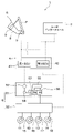
- FIG. 1 is a configuration diagram of a brake system according to a first embodiment
- FIG. It is a side view of a brake device with which a brake system concerning a 1st embodiment is provided.
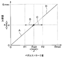
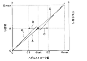
- 7 is a graph showing the relationship between pedal stroke amount and braking force when the first mode is selected; 7 is a graph showing the relationship between the pedal stroke amount and the braking force when the pedal stroke amount reaches a predetermined set value and automatic braking force control is executed when the second mode is selected.
- 7 is a graph showing the relationship between the pedal stroke amount and the braking force after the automatic braking force control is executed when the second mode is selected; 7 is a graph showing the relationship between the actual pedal stroke amount and the corrected pedal stroke amount over time when the second mode is selected; 7 is a flowchart for explaining control processing executed by an ECU when a second mode is selected; It is a graph which shows the relationship between the pedal stroke amount and braking force when the 2nd mode is selected in the brake system which concerns on 2nd Embodiment. It is a graph which shows the relationship between the pedal stroke amount, braking force, and pedal depression force when the 2nd mode is selected in the brake system which concerns on 3rd Embodiment.
- FIG. 11 is a flowchart for explaining control processing executed by an ECU in a brake system according to a fifth embodiment;
- FIG. 12 is a graph showing the relationship between the pedal stroke amount, the braking force, and the pedal depression force when the second mode is selected in the brake system according to the sixth embodiment;
- FIG. 12 is a graph showing the relationship between the pedal stroke amount, the braking force, and the pedal depression force when the second mode is selected in the brake system according to the sixth embodiment;
- FIG. 14 is a graph showing the relationship between the pedal stroke amount, the braking force, and the pedal depression force when the second mode is selected in the brake system according to the seventh embodiment
- FIG. FIG. 12 is a graph showing vertical acceleration acting on the vehicle over time in the brake system according to the eighth embodiment
- FIG. 15B is a graph showing the relationship between the actual pedal stroke amount and the corrected pedal stroke amount in the same time transition as in FIG. 15A
- FIG. 12 is a graph showing the relationship between the actual pedal stroke amount and the corrected pedal stroke amount over time when the second mode is selected in the brake system according to the ninth embodiment
- FIG. It is a figure which shows the positional relationship of the own vehicle in which the brake system which concerns on 9th Embodiment was mounted, and the other vehicle which drive
- FIG. 1 A first embodiment will be described with reference to FIGS. 1 to 7.
- FIG. The brake system 1 of this embodiment is based on the output signal of the sensor 3 that detects the stroke amount ⁇ of the brake pedal 2 mounted on the vehicle. It is a brake-by-wire system that generates braking force.
- the electronic control unit 4 is written as ECU4. Note that ECU is an abbreviation for Electronic Control Unit.
- the ECU 4 is composed of, for example, a well-known microcomputer including a processor and memory, its peripheral circuits, and the like. Note that the memory is a non-transitional material storage medium.
- the brake system 1 includes a brake device 6 that is stepped on by the driver, a brake circuit 5 that generates a braking force for braking the vehicle, an ECU 4 that controls the driving of the brake circuit 5, and a user interface. 7 and so on.
- the brake device 6 includes a support 8 installed on the vehicle body, a brake pedal 2 rotatably provided on the support 8, and a stroke amount ⁇ of the brake pedal 2. It has a sensor 3 and the like for outputting a signal.
- the stroke amount ⁇ of the brake pedal 2 may be referred to as the pedal stroke amount.
- the support 8 is attached to a part of the vehicle body in front of the passenger compartment. Specifically, the support 8 is attached to, for example, a floor or a dash panel in the interior of the vehicle.
- the dash panel is a partition wall that separates the interior of the vehicle from the exterior such as the engine room of the vehicle, and is sometimes called a bulkhead.
- One longitudinal end of the brake pedal 2 is rotatably connected to the support 8 .
- the brake pedal 2 rotates within a predetermined angular range around the rotation axis CL provided on the support 8 .
- the brake pedal 2 is operated by the driver's stepping force.
- FIGS. 1 and 2 exemplify an organ-type brake device 6, the brake device 6 is not limited to this, and may be of a pendant type, for example.
- the organ-type brake device 6 is one in which the part of the brake pedal 2 that is stepped on by the driver is arranged above the rotation axis CL.
- the pendant-type brake device 6 is one in which the part of the brake pedal 2 that is stepped on by the driver is arranged below the rotation axis CL.
- the brake device 6 includes a reaction force generating mechanism 9 that generates a reaction force against the force applied to the brake pedal 2 by the driver.
- a reaction force generating mechanism 9 for example, one or more coil springs, an electric actuator, or a combination thereof can be used.
- the reaction force generating mechanism 9 urges the brake pedal 2 rearward in the vehicle compartment (that is, toward the driver sitting in the driver's seat). Since the brake device 6 includes the reaction force generating mechanism 9, even if the mechanical connection between the brake pedal 2 and the master cylinder 56 is abolished, the brake pedal 2 and the master cylinder 56 are connected. It is possible to obtain the same reaction force as
- the sensor 3 outputs a signal corresponding to the stroke amount ⁇ of the brake pedal 2.
- an angle sensor that outputs a voltage signal corresponding to the rotation angle of the brake pedal 2 can be used.
- the angle sensor for example, a magnetic sensor using a Hall IC or the like, a mechanical sensor, an optical sensor, or the like can be used.
- the rotation angle of the brake pedal 2 corresponds to the pedal stroke amount.
- the sensor 3 is not limited to detecting the rotation angle of the brake pedal 2 as the pedal stroke amount, and may be used to detect the operation amount of the brake pedal 2 or the reaction force generating mechanism 9, for example.
- the electric signal output from the sensor 3 is input to the ECU 4.
- the ECU 4 controls the driving of the brake circuit 5 according to the electric signal output from the sensor 3 of the brake device 6 and the state of the vehicle, and controls the braking force generated by the brake circuit 5 .
- the brake circuit 5 is a mechanism for generating a braking force for braking the vehicle by supplying hydraulic pressure to wheel cylinders 15-18 arranged on the respective wheels 11-14.
- the ECU 4 is composed of a first ECU 41 and a second ECU 42 .
- the brake circuit 5 is composed of a first brake circuit 51 and a second brake circuit 52 .
- the electric signal output from the sensor 3 of the brake device 6 is transmitted to the first ECU 41 and the second ECU 42 .
- the first ECU 41 has a microcomputer, a drive circuit, and the like (not shown).
- the first ECU 41 supplies electric power to the motor 53 of the first brake circuit 51 and the like to drive and control the first brake circuit 51 .
- the second ECU 42 also has a microcomputer and drive circuit (not shown).
- the second 2ECU 42 drives and controls an electromagnetic valve, a motor, and the like (not shown) of the second brake circuit 52 .
- the first brake circuit 51 has a reservoir 55, a motor 53, a gear mechanism 54, a master cylinder 56, and the like.
- the reservoir 55 stores brake fluid.
- a motor 53 drives a gear mechanism 54 .
- the gear mechanism 54 reciprocates a master piston 57 of the master cylinder 56 in the axial direction of the master cylinder 56 . Movement of the master piston 57 increases the hydraulic pressure of the brake fluid supplied from the reservoir 55 to the master cylinder 56 , and the hydraulic pressure is supplied from the first brake circuit 51 to the second brake circuit 52 .
- the second brake circuit 52 is a circuit for performing normal control, ABS control, VSC control, etc. by controlling the hydraulic pressure supplied to each wheel cylinder 15-18 according to the control signal from the second ECU 42.
- ABS stands for Anti-lock Braking System
- VSC stands for Vehicle Stability Control.
- the wheel cylinders 15-18 arranged on the respective wheels 11-14 drive the brake pads provided on the respective wheels 11-14.
- the user interface 7 is a device that enables the driver to give various instructions to the brake system 1.
- the user interface 7 may be, for example, a vehicle-mounted switch, touch panel, or the like, or may use a communication device such as a mobile device.
- Information that the driver operates the user interface 7 is transmitted to the first ECU 41 and the second ECU 42 .
- the user interface 7 of this embodiment is configured so that the driver can instruct the ECU 4 of the brake system 1 to select between the first mode and the second mode. Details of the first mode and the second mode will be described later.
- a signal corresponding to the pedal stroke amount is output from the sensor 3 to the 1ECU 41 and the 2ECU 42.
- the first ECU 41 drives the motor 53 to decelerate the vehicle.
- the master cylinder 56 increases the pressure of the brake fluid supplied from the reservoir 55 .
- the hydraulic pressure of the brake fluid is transmitted from the first brake circuit 51 to the second brake circuit 52 .
- the second 2ECU 42 executes normal control, ABS control, VSC control, and the like.
- the second 2ECU 42 controls the driving of each solenoid valve of the second brake circuit 52 when performing braking with a braking force according to the operation of the brake pedal 2 by the driver.
- the second 2ECU 42 causes the hydraulic pressure supplied from the first brake circuit 51 to be supplied to the wheel cylinders 15 to 18 via the second brake circuit 52 . Accordingly, the brake pads driven by the respective wheel cylinders 15-18 come into frictional contact with the corresponding brake discs, braking the respective wheels 11-14, thereby decelerating the vehicle.
- the second ECU 42 calculates the slip ratio of each wheel 11 to 14 based on the speed of each wheel of the vehicle and the vehicle speed, and executes ABS control. Also, for example, the second ECU 42 calculates the side slip state of the vehicle based on the yaw rate, steering angle, acceleration, speed of each wheel, vehicle speed, and the like, and executes VSC control. Note that the second 2ECU 42 may perform collision avoidance control, regenerative cooperative control, and the like based on signals from other ECUs 4 (not shown).
- the driver can use the user interface 7 to instruct the brake system 1 to select between the first mode and the second mode.
- a signal from the user interface 7 is transmitted to the first ECU 41 and the second ECU 42 .
- the 1ECU 41 and the 2ECU 42 control each part of the brake system 1 based on the signal.
- the control can be performed by either one or both of the 1ECU41 and the 2ECU42. Therefore, in the following description, the 1ECU41 and the 2ECU42 are simply referred to as the ECU4.
- FIG. 3 is a graph showing an example of "basic characteristics", which is the basic relationship between the stroke amount ⁇ of the brake pedal 2 (that is, the pedal stroke amount) and the braking force generated by the brake circuit 5.
- the horizontal axis is the pedal stroke amount
- the vertical axis is the braking force.
- the pedal stroke amount of 0 indicates a state in which the driver's depression force is not applied to the brake pedal 2, and the braking force at this time is zero.
- the pedal stroke amount .theta.max indicates a state in which the driver's depression force is applied to the brake pedal 2 and the brake pedal 2 is moved to the maximum rotational position .theta.max.
- the braking force at this time is the maximum braking force Gmax that can be executed by the vehicle in which the braking system 1 is mounted.
- the ECU 4 When the driver operates the user interface 7 to select the first mode, the ECU 4 performs normal control in the range of the pedal stroke amount from 0 to ⁇ max. When executing normal control, the ECU 4 controls the braking force generated by the brake circuit 5 based on the basic characteristics illustrated in FIG. That is, the ECU 4 increases the braking force as the pedal stroke amount increases, and reduces the braking force as the pedal stroke amount decreases. It should be noted that the ECU 4 sets the braking force to Gmax when the brake pedal 2 has moved to the maximum rotation position ⁇ max.
- the ECU 4 operates the brake circuit based on the basic characteristics as in the first mode. 5 controls the braking force generated. That is, the ECU 4 executes normal control until the pedal stroke amount reaches the set value ⁇ set from 0, increases the braking force as the pedal stroke amount increases, and increases the braking force as the pedal stroke amount decreases. Decrease. As a result, the driver can decelerate the vehicle by operating the brake pedal 2 with a relatively small force while the vehicle is running, thereby adjusting the speed of the vehicle. Note that the arrow A in the graph of FIG. 4 indicates an increase in the pedal stroke amount. Perform normal control based on basic characteristics.
- the ECU 4 determines that the pedal stroke amount is between the first threshold value ⁇ 1 and the second threshold value ⁇ 2, as indicated by arrows B and C in the graph of FIG.
- the braking force automatic control is executed.
- the automatic braking force control is control to set the braking force generated by the brake circuit 5 to a predetermined braking force.
- the first threshold ⁇ 1 is set to a value smaller than the set value ⁇ set, and the second threshold ⁇ 2 is set to a value greater than the set value ⁇ set.
- the ECU 4 maintains the braking force at a predetermined value ⁇ when the pedal stroke amount is between the first threshold value ⁇ 1 and the second threshold value ⁇ 2.
- constant control For example, in the constant braking force control, the ECU 4 determines a correction pedal stroke amount for use in control based on the actual pedal stroke amount (hereinafter referred to as "actual pedal stroke amount") when the driver operates the brake pedal 2. to generate Then, the ECU 4 determines a braking force corresponding to the corrected pedal stroke amount.
- the ECU 4 when the actual pedal stroke amount is between the first threshold value ⁇ 1 and the second threshold value ⁇ 2, the ECU 4 generates the correction pedal stroke amount with a constant value, and the braking force during that period with a constant value ⁇ and As a result, even if the pedal force applied to the brake pedal 2 by the driver during braking of the vehicle varies and the actual pedal stroke amount fluctuates, as long as the actual pedal stroke amount is within the range between the first threshold value ⁇ 1 and the second threshold value ⁇ 2. , the vehicle is braked with a predetermined braking force ⁇ . Therefore, even if the driver does not finely adjust the brake pedal 2, smooth braking can be achieved with a simple pedal operation.
- the predetermined value ⁇ at which the braking force is constant may be set in advance and stored in the ECU 4, or the ECU 4 may set an appropriate value according to the vehicle speed or deceleration acceleration. may
- the ECU 4 controls the braking force generated by the brake circuit 5 based on the basic characteristics as in the first mode. . That is, when the pedal stroke amount becomes greater than the second threshold value ⁇ 2, the ECU 4 cancels the constant braking force control and executes the normal control, increases the braking force according to the increase in the pedal stroke amount, and reduces the pedal stroke amount. Reduce the braking force accordingly.
- the ECU 4 executes normal control based on the basic characteristics, so the braking force becomes Gmax when the brake pedal 2 is at the maximum rotation position ⁇ max.
- the driver can stop the vehicle at an arbitrary stop position by increasing the pedaling force applied to the brake pedal 2 and making the pedal stroke larger than the second threshold value ⁇ 2 during vehicle braking.
- the driver makes the pedal stroke larger than the second threshold value ⁇ 2 even when a situation requiring a sudden stop or sudden deceleration such as a sudden jumping out of the vehicle or an interruption by another vehicle occurs. This makes it possible to stop or decelerate the vehicle suddenly.
- the maximum braking force Gmax is achieved when the pedal stroke is at the maximum rotation position ⁇ max without deteriorating the comfort of stepping on the brake pedal 2 when the pedal stroke is between the second threshold value ⁇ 2 and the maximum rotation position ⁇ max. can be generated. Therefore, this brake system 1 can enhance the driver's sense of security and improve reliability and safety.
- FIG. 6 shows the relationship between the time elapsed after the driver starts operating the brake pedal 2, the actual pedal stroke amount, and the correction pedal stroke amount when the second mode is selected.
- the actual pedal stroke amount and the corrected pedal stroke amount match from time T0 to time T1 and after time T3.
- the actual pedal stroke amount is indicated by the one-dot chain line E, and the corrected pedal stroke amount during that period is indicated by the solid lines F and G.
- the driver starts applying the force to the brake pedal 2 after time T0. Since the ECU 4 executes normal control from time T0 to time T1, the actual pedal stroke amount of the brake pedal 2 operated by the driver and the corrected pedal stroke amount generated by the ECU 4 are the same. Therefore, from time T0 to time T1, the braking force increases as the actual pedal stroke increases.
- the actual pedal stroke amount reaches the set value ⁇ set.
- the actual pedal stroke amount is between the first threshold value ⁇ 1 and the second threshold value ⁇ 2. Therefore, as indicated by the solid line F, the ECU 4 starts constant braking force control at time T1, and thereafter generates the corrected pedal stroke amount at a constant value ⁇ set from time T1 to time T2. Therefore, from time T1 to time T2, the braking force is kept at a constant value ⁇ based on the corrected pedal stroke amount.
- the ECU 4 cancels the constant braking force control and shifts to normal control.
- the ECU 4 increases the corrected pedal stroke amount at a predetermined rate of increase after time T2. It is assumed that the increase rate per unit time of the corrected pedal stroke amount at this time is set in advance by experiments or the like and stored in the ECU 4 .
- the ECU 4 When the corrected pedal stroke amount and the actual pedal stroke amount match at time T3, the ECU 4 thereafter sets the actual pedal stroke amount and the corrected pedal stroke amount to the same value as indicated by the solid line I. Therefore, after time T3, the braking force is set according to the actual pedal stroke amount.
- a transition period is provided for transitioning from the constant braking force control to the normal control, and the braking force increases from the predetermined value ⁇ to the actual pedal stroke. It is designed to continuously change to a value corresponding to . This prevents the passengers including the driver from feeling uncomfortable.
- step S10 in FIG. 7 the ECU 4 executes this control process while the vehicle is running.
- step S20 the driver applies a force to the brake pedal 2 and starts depressing the brake pedal 2 in order to decelerate or stop the vehicle.
- the pedal stroke amount ⁇ when the brake pedal 2 is started to be depressed is smaller than the first threshold value ⁇ 1.
- a sensor 3 included in the brake device 6 outputs a signal corresponding to the pedal stroke amount ⁇ to the ECU 4 .
- step S ⁇ b>30 the ECU 4 detects the pedal stroke amount ⁇ from the output signal of the sensor 3 .
- step S40 the ECU 4 determines whether or not the pedal stroke amount ⁇ has reached the set value ⁇ set. When the ECU 4 determines that the pedal stroke amount ⁇ has not reached the set value ⁇ set (that is, determination NO in step S40), the process proceeds to step S50.
- step S50 the ECU 4 executes normal control.
- normal control the ECU 4 decelerates the vehicle with a braking force corresponding to the pedal stroke amount ⁇ . Then, the ECU 4 returns the process to step S30.
- step S40 determines in the process of step S40 that the pedal stroke amount ⁇ has reached the set value ⁇ set (that is, the determination of step S40 is YES), the process proceeds to step S60.
- step S60 the ECU 4 executes braking force automatic control to set the braking force to a predetermined braking force.
- the ECU 4 executes constant braking force control to keep the braking force constant as an example of automatic braking force control. Then, the ECU 4 advances the process to step S70.
- step S70 the driver continues to depress the brake pedal 2 in order to decelerate or stop the vehicle.
- step S ⁇ b>80 the ECU 4 detects the pedal stroke amount ⁇ from the output signal of the sensor 3 .
- step S90 the ECU 4 determines whether or not the pedal stroke amount ⁇ is between the first threshold ⁇ 1 and the second threshold ⁇ 2.
- the process proceeds to step S100.
- step S100 the ECU 4 continues to perform the automatic braking force control.
- the ECU 4 continuously executes constant braking force control as an example of automatic braking force control. Then, the ECU 4 returns the process to step S80.
- step S90 determines in the process of step S90 that the pedal stroke amount ⁇ is not between the first threshold value ⁇ 1 and the second threshold value ⁇ 2 (that is, determination NO in step S90), the process proceeds to step S110. .
- the ECU 4 cancels the braking force automatic control and executes normal control.
- normal control the ECU 4 decelerates the vehicle with a braking force corresponding to the pedal stroke amount ⁇ .
- step S120 the ECU 4 temporarily terminates the control process when the vehicle stops running. However, when the vehicle is running and the pedal stroke amount ⁇ is smaller than the first threshold value ⁇ 1, the ECU 4 returns the process to step S20. On the other hand, when the vehicle is running and the pedal stroke amount ⁇ is greater than the second threshold value ⁇ 2, the normal control of step S110 is continued.
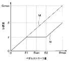
- FIG. 18 It should be noted that the braking systems of the first comparative example and the second comparative example were created by the applicant of the present disclosure, and are not prior art.
- FIG. 18 shows the relationship between the pedal stroke amount and the braking force in the first comparative example. Also in the first comparative example, the driver can operate the user interface 7 to select between the first mode and the second mode.
- a dashed line M in FIG. 18 indicates the relationship between the pedal stroke amount and the braking force when the first mode is selected, and the solid line N indicates the pedal stroke amount when the second mode is selected. It shows the relationship with the braking force. However, it is assumed that the dashed line M and the solid line N overlap when the pedal stroke amount is 0 to ⁇ 1.
- the ECU 4 performs normal control when the first mode is selected.
- the braking force generated by the brake circuit 5 is controlled based on the basic characteristics, which are the basic relationship between the stroke amount and the braking force, in the range of the pedal stroke amount from 0 to ⁇ max.
- the braking force when the brake pedal 2 is moved to the maximum rotation position ⁇ max is the maximum braking force Gmax that can be performed by the vehicle equipped with the brake system 1 .
- the ECU 4 performs normal control in the range of the pedal stroke amount from 0 to the first threshold value ⁇ 1. After the pedal stroke amount reaches the first threshold value ⁇ 1, the ECU 4 sets the braking force to a predetermined constant braking force when the pedal stroke amount is between the first threshold value ⁇ 1 and the second threshold value ⁇ 2. The constant braking force control is executed as ⁇ . Then, when the pedal stroke amount becomes larger than the second threshold value ⁇ 2, the ECU 4 cancels the constant braking force control and executes control for increasing or decreasing the braking force according to the increase or decrease in the pedal stroke amount.
- the braking force ⁇ when the brake pedal 2 is moved to the maximum rotation position ⁇ max when the second mode is selected becomes a value smaller than the maximum braking force Gmax that the vehicle can perform.
- FIG. 19 shows the relationship between the pedal stroke amount and the braking force in the second comparative example.
- the driver can operate the user interface 7 to select between the first mode and the second mode.
- a dashed line O in FIG. 19 indicates the relationship between the pedal stroke amount and the braking force when the first mode is selected
- the solid line P indicates the pedal stroke amount when the second mode is selected. It shows the relationship with the braking force.
- the dashed line O and the solid line P overlap when the pedal stroke amount is 0 to ⁇ 1.
- the ECU 4 executes the normal control as in the first comparative example. Further, as indicated by the solid line P, when the second mode is selected, the ECU 4 performs the same control as the control described in the first comparative example within the range of the pedal stroke amount from 0 to the second threshold value ⁇ 2. . Then, when the pedal stroke amount becomes larger than the second threshold value ⁇ 2, the ECU 4 cancels the constant braking force control and executes control for increasing or decreasing the braking force according to the increase or decrease in the pedal stroke amount.
- the rate of increase of the braking force with respect to the increase in the pedal stroke amount is made larger than the basic characteristic. Therefore, in the second comparative example, the braking force when the brake pedal 2 is moved to the maximum rotation position ⁇ max is the maximum braking force Gmax that the vehicle can perform.
- the increase rate of the braking force with respect to the increase in the pedal stroke amount is made larger than the basic characteristic as in the second comparative example, there is a possibility that the feeling of stepping on the brake pedal 2 by the driver may deteriorate.
- the brake system 1 of the first embodiment described above has the following effects.
- the ECU 4 reduces the braking force generated by the brake circuit 5 to A braking force automatic control is executed to set a predetermined braking force. Therefore, when the automatic braking force control is executed, even if the pedal stroke amount fluctuates due to variations in the pedaling force applied to the brake pedal 2 by the driver, the pedal stroke amount will be between the first threshold value ⁇ 1 and the second threshold value ⁇ 2. If there is in between, stable braking of the vehicle takes place. Therefore, the brake system 1 enables stable braking of the vehicle with a simple pedal operation by the driver, and can reduce the driver's stress associated with the operation of the brake pedal 2 .
- the ECU 4 controls the braking force generated by the brake circuit 5 with the braking force based on the basic characteristics when the pedal stroke amount exceeds the second threshold value ⁇ 2. Therefore, in this brake system 1, even after the pedal stroke amount exceeds the second threshold value ⁇ 2 when the second mode is selected, the feeling of stepping on the brake pedal 2 does not deteriorate, and when the pedal stroke amount is at the maximum rotation position ⁇ max, It is possible to generate the maximum braking force Gmax at . Therefore, this brake system 1 can enhance the driver's sense of security and improve reliability and safety.
- the braking force automatic control executed by the ECU 4 is constant braking force control that keeps the braking force constant. According to this, even if the depressing force applied to the brake pedal 2 by the driver fluctuates to some extent, the deceleration G during braking of the vehicle is kept constant as long as the pedal stroke amount is between the first threshold value ⁇ 1 and the second threshold value ⁇ 2. maintained and smooth braking is achieved. Therefore, it is possible to improve the riding comfort during braking of the vehicle.
- Second to tenth embodiments will be described. Also in the second to tenth embodiments, the driver can operate the user interface 7 to select between the first mode and the second mode, as in the first embodiment. Also in the second to tenth embodiments, the normal control executed by the ECU 4 when the first mode is selected is the same as the normal control described in the first embodiment. Therefore, in the following description, mainly the control executed by the ECU 4 when the second mode is selected will be described.
- the ECU 4 adjusts the braking force generated by the brake circuit 5 based on the basic characteristics until the pedal stroke amount is greater than 0 and reaches a predetermined set value ⁇ set. Control. Then, as indicated by arrows B and C, after the pedal stroke amount reaches the set value ⁇ set, when the pedal stroke amount is between the first threshold value ⁇ 1 and the second threshold value ⁇ 2, the ECU 4 preliminarily sets the braking force. Automatic braking force control is executed to set the determined braking force. Also in the second embodiment, the ECU 4 executes "braking force constant control" to keep the braking force constant at a predetermined value ⁇ as an example of automatic braking force control.
- the ECU 4 cancels the braking force constant control and executes normal control. That is, the ECU 4 controls the braking force generated by the brake circuit 5 based on the basic characteristics when the pedal stroke amount is between the second threshold value ⁇ 2 and the maximum rotation position ⁇ max. This is the same as the content explained in the first embodiment also in the second embodiment.
- the driver can adjust at least one of the braking forces ⁇ when the control is executed to any value.
- This adjustment can be performed by the driver operating the user interface 7 .
- the user interface 7 may be mounted on the vehicle, for example, to enable continuous value adjustment using a dial or stepwise value adjustment using an UP/DOWN button.
- the user interface 7 may utilize communication equipment such as mobile devices.
- Information that the driver operates the user interface 7 is transmitted to the ECU 4 . That is, by operating the user interface 7, the driver can set at least one of the set value ⁇ set of the pedal stroke amount and the braking force ⁇ when the constant braking force control is executed to an arbitrary value continuously or stepwise. can be adjusted accordingly.
- the value adjusted for each identified driver is recorded in the ECU 4, and at the next and subsequent driving occasions, the It may be configured to set a value.
- a system capable of identifying a driver for example, it is possible to use a driver status monitor or authentication by a mobile device.
- the user interface 7 continuously changes at least one of the set value ⁇ set of the pedal stroke amount and the braking force when the automatic braking force control is executed. Or it is configured to be adjustable step by step. According to this, the driver can operate the user interface 7 to adjust the braking force of the automatic braking force control according to his/her preferred driving style.
- the third embodiment is an example in which the pedaling force applied to the brake pedal 2 by the driver (that is, the reaction force generated by the reaction force generating mechanism 9) and the pedal stroke amount are interlocked.
- the force applied to the brake pedal 2 by the driver is referred to as "pedal force”.
- the dashed-dotted line Q indicates the pedaling force with respect to the pedal stroke amount.
- the brake pedal 2 usually has such a characteristic that the pedaling force applied to the brake pedal 2 by the driver increases as the pedal stroke increases.
- a technique has begun to appear in which an actuator is mounted in place of or together with a mechanical or hydraulic reaction force generating mechanism 9 to vary the pedaling force.
- a system is assumed in which the pedal effort can be varied by an actuator.
- the point where the pedal effort temporarily decreases near the set value ⁇ set while the pedal stroke is increasing (hereinafter referred to as (referred to as a “pedal force changing portion”). This makes it easier for the driver to maintain the pedal stroke at the pedal stroke amount (that is, around the set value ⁇ set) at which the control is switched from the normal control to the automatic braking force control.
- the ECU 4 when the second mode is selected, the ECU 4 outputs Automatic braking force control (for example, constant braking force control) is executed. Specifically, after the pedal stroke amount reaches the first set value ⁇ set1, when the pedal stroke amount is between the first threshold value ⁇ 1 and the second threshold value ⁇ 2, the ECU 4 performs "first braking force automatic control. ”. Further, after the pedal stroke amount increases and reaches the second set value ⁇ set2, when the pedal stroke amount is between the third threshold value ⁇ 3 and the fourth threshold value ⁇ 4, the ECU 4 performs the second braking force automatic control. ”. The braking force by the "first automatic braking force control" is constant at ⁇ 1, and the braking force by the "second automatic braking force control" is constant at ⁇ 2.
- Automatic braking force control for example, constant braking force control
- a plurality of pedaling force change portions are provided in the middle of the pedal stroke.
- a plurality of pedaling force change sections are assigned to a plurality of set values ⁇ set1 and ⁇ set2 at which control is switched from normal control to braking force automatic control.
- automatic braking force control is set at two points in the middle of the pedal stroke, but the present invention is not limited to this. may be set.
- the ECU 4 included in the brake system 1 of the fifth embodiment executes the control process shown in the flowchart of FIG. 11 while the vehicle is running.
- step S200 the ECU 4 estimates the road surface friction coefficient.
- ECU4 may measure a road surface friction coefficient directly.
- the coefficient of friction is expressed as ⁇ .
- step S210 the ECU 4 determines that there is a possibility of tire slip when braking is performed with a predetermined braking force ⁇ (hereinafter referred to as "standard braking force ⁇ " as appropriate) when constant braking force control is executed. Determine whether or not
- step S210 determines in step S210 that there is little or no possibility of tire slip. If the ECU 4 determines in step S210 that there is little or no possibility of tire slip, the process ends. On the other hand, when the ECU 4 determines in step S210 that the possibility of tire slip is present or high, the process proceeds to step S220.
- step S220 the ECU 4 changes the braking force when the constant braking force control is executed to a braking force ⁇ (hereinafter referred to as "anti-slip braking force ⁇ ") with a smaller standard braking force ⁇ .
- This process is called a braking force change process.
- step S230 the ECU 4 notifies the driver that the braking force changing process has been executed by various means such as voice, screen display, or vibration.
- the driver can recognize that the standard braking force ⁇ , which is executed under constant braking force control, is automatically switched to the anti-slip braking force ⁇ , so that the driver does not feel uneasy.
- the process of changing the braking force when the constant braking force control is executed is performed. It is not limited to that.
- the control may be switched from the second mode to the first mode. After switching the control to the first mode, the ECU 4 performs normal control over the entire pedal stroke amount. Also in this case, the ECU 4 notifies the driver that the control has been switched from the second mode to the first mode by various means such as voice, screen display, or vibration. As a result, the driver can recognize that the control has been automatically switched, so that he or she does not feel uneasy.
- Arrows A, B, C and solid line D in the graph of FIG. 12 are controls executed by the ECU 4 when it is determined from the tread surface friction coefficient that the possibility of tire slip is almost non-existent or low in the fifth embodiment.
- the braking force for the automatic braking force control is set to the standard braking force ⁇ .
- arrows S, T, and U are controls executed by the ECU 4 when it is determined that there is a possibility or a high possibility of tire slip based on the tread friction coefficient.
- the braking force for the automatic braking force control is set to the anti-slip braking force ⁇ .
- the dashed-dotted line V in the graph of FIG. 12 shows the pedal effort against the pedal stroke amount when it is determined from the tread surface friction coefficient that there is little or no possibility of tire slip. against the pedaling force applied to the brake pedal 2 by the driver
- the two-dot chain line W in the graph of FIG. 12 shows the pedal effort against the pedal stroke amount when it is determined that there is a high possibility of tire slip from the coefficient of friction on the tread surface.
- the ECU 4 interlocks with the braking force changing process for changing the braking force of the automatic braking force control from the standard braking force ⁇ to the anti-slip braking force ⁇ , and the pedal depression force (that is, the reaction force generated by the reaction force generating mechanism 9 ).
- the ECU 4 increases the reaction force by the actuator that constitutes the reaction force generating mechanism 9 when the stroke amount is larger than the pedal stroke amount ⁇ set2 corresponding to the anti-slip braking force ⁇ .
- this fifth embodiment is a control focused on not causing tire slip in principle, and in a situation where it is judged that tire slip is actually occurring, the ABS control that has been adopted in conventional vehicles is used. It is assumed to operate with priority.
- the braking force change process or mode execute at least one of the modification processes.
- the braking force changing process is a process of setting the braking force at the time of executing the automatic braking force control to a braking force ⁇ smaller than a predetermined standard braking force ⁇ . This is the process of changing the mode.
- the ECU 4 is configured to notify the driver that the braking force change process or mode change process has been executed.
- the ECU 4 can prevent tire slip by determining the possibility of tire slip during execution of the braking force automatic control and setting the braking force to be smaller than the standard braking force ⁇ . Further, the ECU 4 notifies the driver that the braking force change process or the mode change process has been executed so as not to make the driver uneasy, widens the distance between the vehicles, and operates the brake pedal 2 early. It is possible to recommend preventive driving such as
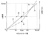
- a dashed-dotted line Q in the graph of FIG. 13 indicates the relationship between the pedal stroke amount and the pedaling force (hereinafter referred to as the pedaling force characteristic of the brake pedal 2).
- the pedaling force characteristic of the brake pedal 2 As indicated by a point R in the middle of the one-dot chain line Q, an inflection point is provided in the middle of the pedaling force characteristic of the brake pedal 2 at which the pedaling force characteristic of the brake pedal 2 changes.
- the inflection point at which the brake pedal depression force characteristic is switched coincides with the set value ⁇ set at which the braking control mode is switched.
- the inflection point of the pedaling force characteristic of the brake pedal 2 may be formed by a mechanical spring force generated by the reaction force generating mechanism 9 provided in the brake device 6, or may be formed by an actuator.
- the reaction force generating mechanism 9 provided in the brake device 6 has one or more inflection points that change the relationship between the stroke amount and the reaction force, and has at least one inflection point.
- a point is set at a pedal stroke amount corresponding to a predetermined set value ⁇ set. According to this, when the pedal stroke amount ⁇ reaches the predetermined set value ⁇ set, the reaction force changes due to the inflection point. Therefore, the driver can intuitively know that the execution of the braking force automatic control has started by the feeling transmitted from the brake pedal 2 to the driver's foot.
- (Seventh embodiment) 7th Embodiment shall be a modification of 6th Embodiment, and the reaction force generation mechanism 9 with which the brake device 6 is provided shall be comprised by the actuator.
- the point of inflection at which the pedaling force characteristic of the brake pedal 2 switches is set to the mode of braking control. is matched with the set value ⁇ set at which is switched.
- the pedaling force characteristic can be arbitrarily adjusted as indicated by hatching between the dashed-dotted lines Q1 and Q2 in the graph of FIG. be able to.
- FIG. 15A is a graph showing vertical acceleration acting on the vehicle over time (hereinafter referred to as "vehicle vertical G") while constant braking force control is being executed by the ECU 4 provided in the brake system 1. is.
- the vertical G of the vehicle increases.
- the acceleration in the vertical direction may be directly measured by an acceleration sensor mounted on the vehicle.
- the magnitude of the unevenness of the road surface may be determined from the output signal of the axle torque sensor or the tire grip force sensor. It is also conceivable to determine the size of road unevenness based on image recognition by a forward recognition camera.
- the ECU 4 provided in the brake system 1 determines that the vehicle vertical G is greatly fluctuating, for example, when the value of the vehicle vertical G exceeds predetermined upper acceleration threshold TH1 and lower acceleration threshold TH2.
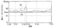
- FIG. 15B is a graph showing the relationship between the actual pedal stroke amount and the corrected pedal stroke amount in the same time transition as in FIG. 15A.
- the actual pedal stroke amount is indicated by a dashed line E1
- the corrected pedal stroke amount is indicated by a solid line F1.
- the corrected pedal stroke amount is constant during the period from time T10 to time T15 because the constant braking force control is executed by the ECU 4 .
- the actual pedal stroke amount indicated by the one-dot chain line E1 exceeds the second threshold ⁇ 2 between times T12 and T13, and falls below the second threshold ⁇ 2 before and after that.
- the ECU 4 controls the time zone in which the vehicle vertical G changes more than the vertical acceleration threshold values TH1 and TH2 and the time zone in which the actual pedal stroke amount deviates from the region between the first threshold value ⁇ 1 and the second threshold value ⁇ 2. and at least partially overlap each other, the automatic braking force control is maintained. Therefore, the ECU 4 continues to execute the braking force constant control even during the time T12 to T13, and keeps the correction pedal stroke amount shown by the solid line F1 constant.
- the ECU 4 controls the time zone in which the vehicle vertical G changes more than a predetermined vertical acceleration threshold and the time zone in which the pedal stroke deviates from the region between the first threshold value ⁇ 1 and the second threshold value ⁇ 2.
- the automatic braking force control is maintained.
- the ECU 4 determines that the operation is not intentional by the driver. and maintain the automatic braking force control. As a result, it is possible to prevent the driver from feeling uncomfortable due to an unintended change in the braking force.
- FIG. 16 is a graph showing the relationship between the actual pedal stroke amount and the corrected pedal stroke amount over time when the second mode is selected in the brake system 1 according to the ninth embodiment.
- FIG. 16 shows a state in which the driver stops or decelerates the vehicle by a normal operation, and a state in which the driver suddenly applies a pedaling force to the brake pedal 2 (i.e., applies a sudden brake) to stop the vehicle. Both states are described when the is suddenly stopped or suddenly decelerated.
- Solid lines H2, F2 and one-dot chain line E2 in FIG. 16 show the state when the driver stops or decelerates the vehicle by normal operation. Specifically, as indicated by the solid line H2, the actual pedal stroke amount and the corrected pedal stroke amount match from time T20 to time T22. Further, from time T22 to time T23, the actual pedal stroke amount is indicated by the one-dot chain line E2, and the corrected pedal stroke amount during that period is indicated by the solid line F2.
- the driver When the driver stops or decelerates the vehicle by normal operation, the driver starts applying the force to the brake pedal 2 after time T20. Since the ECU 4 executes normal control from time T20 to time T22, the actual pedal stroke amount and the corrected pedal stroke amount during that period match.
- the actual pedal stroke amount reaches the set value ⁇ set.
- the actual pedal stroke amount is between the first threshold ⁇ 1 and the second threshold ⁇ 2. Therefore, as indicated by the solid line F2, from time T22 to time T23, the ECU 4 executes the braking force constant control to generate the corrected pedal stroke amount with a constant value ⁇ set. Therefore, from time T22 to time T23, the braking force is kept at a constant value based on the corrected pedal stroke amount.
- the solid line X in FIG. 16 shows the state in which the driver suddenly applies a force to the brake pedal 2 (i.e., applies a sudden brake) to stop or decelerate the vehicle. It is. At this time, the driver instantaneously requests a larger braking force than usual (that is, a braking force corresponding to ⁇ > ⁇ 2) due to sudden braking.
- the pedal operation when the driver instantaneously requests a braking force greater than normal (that is, a braking force corresponding to ⁇ > ⁇ 2) is It is considered that the condition is almost equivalent to that the rate of change with time is large.
- the time rate of change of the pedal stroke amount is represented by ⁇ / ⁇ T in FIG. 16, and can be rephrased as the increase rate of the pedal stroke amount per unit time.
- the ECU 4 temporarily turns off the automatic braking force control function even if the second mode is selected when the time rate of change of the pedal stroke amount exceeds a certain threshold value before the pedal stroke amount reaches ⁇ set. , the normal control is executed over the entire pedal stroke amount. That is, in FIG.
- the ECU 4 since the time rate of change of the pedal stroke amount (that is, ⁇ / ⁇ T) exceeds a certain threshold before time T21 when the pedal stroke amount reaches ⁇ set, the ECU 4 performs the function of automatic braking force control. is turned off and normal control is executed. By doing so, in a scene where a braking force corresponding to ⁇ > ⁇ 2 is required instantaneously, it is possible to prevent the driver from feeling uncomfortable due to a step in the braking force.
- the operation with a large rate of change of the pedal stroke amount over time (that is, ⁇ / ⁇ T) is considered to be due to a sudden change in the external environment other than the own vehicle and the strong depression of the brake pedal 2 on the spur of the moment. receive.
- ⁇ / ⁇ T the rate of change of the pedal stroke amount over time
- the ECU 4 can use information obtained from the sensors to determine whether the function is temporarily turned off.
- the ECU 4 selects the second mode, and before the pedal stroke amount increases and reaches the predetermined set value ⁇ set, the ECU 4 determines that the time rate of change of the pedal stroke amount is greater than the predetermined threshold value. In this case, the automatic braking force control is not executed, and the normal control is executed. Note that the time rate of change of the pedal stroke amount can also be rephrased as an increase rate of the pedal stroke amount per unit time. According to this, in the scene where the driver desires that the braking force corresponding to the pedal stroke amount equal to or greater than the second threshold value ⁇ 2 is instantaneously generated, the ECU 4 switches the braking force automatic control to the normal control. As a result, it is possible to prevent discomfort caused by a change in the braking force when switching from the automatic braking force control to the normal control when the second threshold value ⁇ 2 or more is reached.
- the vehicle The braking force may be controlled so that the
- the braking force may gradually decrease with time.
- the braking force may be feedback-controlled so that the deceleration G is constant, or the braking force may be feedback-controlled so that the deceleration G gradually decreases with time. may be controlled.
- the ECU 4 is composed of the first ECU 41 and the second ECU 42.
- the ECU 4 is not limited to this. may be configured.
- the "basic characteristics" which are the basic relationships between the pedal stroke amount and the braking force, are linear, but these are examples, and the basic characteristics are non-linear. There may be.
- the present disclosure is not limited to the above-described embodiments, and can be modified as appropriate. Moreover, the above-described embodiments are not unrelated to each other, and can be appropriately combined unless the combination is clearly impossible. Further, in each of the above-described embodiments, it goes without saying that the elements constituting the embodiment are not necessarily essential, unless it is explicitly stated that they are essential, or they are clearly considered essential in principle. stomach. In addition, in each of the above-described embodiments, when numerical values such as the number, numerical value, amount, range, etc.
- control apparatus and techniques described in this disclosure may be implemented by a dedicated computer provided by configuring a processor and memory programmed to perform one or more functions embodied by the computer program.
- the controller and techniques described in this disclosure may be implemented by a dedicated computer provided by configuring the processor with one or more dedicated hardware logic circuits.
- the control apparatus and techniques described in this disclosure can be implemented by a combination of a processor and memory programmed to perform one or more functions and a processor configured by one or more hardware logic circuits. It may also be implemented by one or more dedicated computers configured.
- the computer program may also be stored as computer-executable instructions on a computer-readable non-transitional tangible recording medium.
Landscapes
- Engineering & Computer Science (AREA)
- Transportation (AREA)
- Mechanical Engineering (AREA)
- Regulating Braking Force (AREA)
- Braking Elements And Transmission Devices (AREA)
Priority Applications (3)
| Application Number | Priority Date | Filing Date | Title |
|---|---|---|---|
| DE112022001255.2T DE112022001255T5 (de) | 2021-02-25 | 2022-02-09 | Bremssystem und elektronik steuerungsvorrichtung |
| CN202280016623.0A CN116917174A (zh) | 2021-02-25 | 2022-02-09 | 制动系统和电子控制装置 |
| US18/451,541 US20230391299A1 (en) | 2021-02-25 | 2023-08-17 | Brake system and electronic control device |
Applications Claiming Priority (2)
| Application Number | Priority Date | Filing Date | Title |
|---|---|---|---|
| JP2021-029095 | 2021-02-25 | ||
| JP2021029095A JP7537306B2 (ja) | 2021-02-25 | 2021-02-25 | ブレーキシステム、および、電子制御装置 |
Related Child Applications (1)
| Application Number | Title | Priority Date | Filing Date |
|---|---|---|---|
| US18/451,541 Continuation US20230391299A1 (en) | 2021-02-25 | 2023-08-17 | Brake system and electronic control device |
Publications (1)
| Publication Number | Publication Date |
|---|---|
| WO2022181329A1 true WO2022181329A1 (ja) | 2022-09-01 |
Family
ID=83048269
Family Applications (1)
| Application Number | Title | Priority Date | Filing Date |
|---|---|---|---|
| PCT/JP2022/005055 Ceased WO2022181329A1 (ja) | 2021-02-25 | 2022-02-09 | ブレーキシステム、および、電子制御装置 |
Country Status (5)
| Country | Link |
|---|---|
| US (1) | US20230391299A1 (https=) |
| JP (1) | JP7537306B2 (https=) |
| CN (1) | CN116917174A (https=) |
| DE (1) | DE112022001255T5 (https=) |
| WO (1) | WO2022181329A1 (https=) |
Cited By (7)
| Publication number | Priority date | Publication date | Assignee | Title |
|---|---|---|---|---|
| CN117022211A (zh) * | 2023-10-10 | 2023-11-10 | 金琥新能源汽车(成都)有限公司 | 一种防抱死驻车方法、装置、设备及存储介质 |
| US12204360B2 (en) | 2021-02-25 | 2025-01-21 | Denso Corporation | Pedal device |
| US12248332B2 (en) | 2021-02-25 | 2025-03-11 | Denso Corporation | Pedal device |
| US12292756B2 (en) | 2021-02-25 | 2025-05-06 | Denso Corporation | Pedal device |
| US12384332B2 (en) | 2021-02-25 | 2025-08-12 | Denso Corporation | Pedal device |
| US12509029B2 (en) | 2021-02-25 | 2025-12-30 | Denso Corporation | Pedal device |
| US12539833B2 (en) * | 2023-08-09 | 2026-02-03 | Hyundai Motor Company | Device for changing braking mode and method of changing braking mode |
Families Citing this family (5)
| Publication number | Priority date | Publication date | Assignee | Title |
|---|---|---|---|---|
| JP7225187B2 (ja) * | 2020-12-03 | 2023-02-20 | 本田技研工業株式会社 | 車両用ブレーキシステム |
| WO2026042589A1 (ja) * | 2024-08-20 | 2026-02-26 | 株式会社Soken | ブレーキ制御装置、ブレーキ制御方法およびブレーキ制御プログラム |
| CN119099565B (zh) * | 2024-09-30 | 2025-09-19 | 长城汽车股份有限公司 | 车辆制动踏板的控制方法、装置、电子设备及车辆 |
| CN119261829B (zh) * | 2024-10-31 | 2025-09-26 | 奇瑞新能源汽车股份有限公司 | 自动驻车控制方法、装置、电子设备及存储介质 |
| CN119611281A (zh) * | 2024-12-26 | 2025-03-14 | 浙江吉利控股集团有限公司 | 制动踏板的控制方法、装置、控制器及液压制动系统 |
Citations (3)
| Publication number | Priority date | Publication date | Assignee | Title |
|---|---|---|---|---|
| JP2016088353A (ja) * | 2014-11-07 | 2016-05-23 | 本田技研工業株式会社 | 車両用制動制御装置 |
| JP2017144945A (ja) * | 2016-02-19 | 2017-08-24 | マツダ株式会社 | 自動車の制動装置 |
| JP2020117175A (ja) * | 2019-01-28 | 2020-08-06 | 株式会社アドヴィックス | 車両の制動装置 |
Family Cites Families (10)
| Publication number | Priority date | Publication date | Assignee | Title |
|---|---|---|---|---|
| DE19703688B4 (de) * | 1997-01-31 | 2006-02-09 | Robert Bosch Gmbh | Verfahren und Vorrichtung zur Steuerung einer Bremsanlage |
| JP4525422B2 (ja) * | 2005-03-30 | 2010-08-18 | 株式会社アドヴィックス | 車両用ブレーキ装置 |
| JP4563851B2 (ja) * | 2005-03-31 | 2010-10-13 | 本田技研工業株式会社 | ブレーキ装置 |
| JP5250379B2 (ja) | 2008-10-14 | 2013-07-31 | 日立オートモティブシステムズ株式会社 | ブレーキ制御装置 |
| JP5740905B2 (ja) * | 2010-10-20 | 2015-07-01 | 日産自動車株式会社 | 車両用制動力制御装置 |
| WO2012105526A1 (ja) * | 2011-01-31 | 2012-08-09 | 本田技研工業株式会社 | 車両用ブレーキ装置 |
| JP5761057B2 (ja) * | 2012-02-02 | 2015-08-12 | トヨタ自動車株式会社 | ブレーキ制御装置 |
| KR102042608B1 (ko) * | 2018-09-06 | 2019-11-27 | 주식회사 만도 | 전자식 브레이크 시스템 |
| JP6964626B2 (ja) * | 2019-06-24 | 2021-11-10 | 本田技研工業株式会社 | 車両用走行制御装置 |
| CN110395135A (zh) | 2019-08-12 | 2019-11-01 | 深圳市智引科技有限公司 | 一种自动机械手 |
-
2021
- 2021-02-25 JP JP2021029095A patent/JP7537306B2/ja active Active
-
2022
- 2022-02-09 DE DE112022001255.2T patent/DE112022001255T5/de active Pending
- 2022-02-09 CN CN202280016623.0A patent/CN116917174A/zh active Pending
- 2022-02-09 WO PCT/JP2022/005055 patent/WO2022181329A1/ja not_active Ceased
-
2023
- 2023-08-17 US US18/451,541 patent/US20230391299A1/en active Pending
Patent Citations (3)
| Publication number | Priority date | Publication date | Assignee | Title |
|---|---|---|---|---|
| JP2016088353A (ja) * | 2014-11-07 | 2016-05-23 | 本田技研工業株式会社 | 車両用制動制御装置 |
| JP2017144945A (ja) * | 2016-02-19 | 2017-08-24 | マツダ株式会社 | 自動車の制動装置 |
| JP2020117175A (ja) * | 2019-01-28 | 2020-08-06 | 株式会社アドヴィックス | 車両の制動装置 |
Cited By (8)
| Publication number | Priority date | Publication date | Assignee | Title |
|---|---|---|---|---|
| US12204360B2 (en) | 2021-02-25 | 2025-01-21 | Denso Corporation | Pedal device |
| US12248332B2 (en) | 2021-02-25 | 2025-03-11 | Denso Corporation | Pedal device |
| US12292756B2 (en) | 2021-02-25 | 2025-05-06 | Denso Corporation | Pedal device |
| US12384332B2 (en) | 2021-02-25 | 2025-08-12 | Denso Corporation | Pedal device |
| US12509029B2 (en) | 2021-02-25 | 2025-12-30 | Denso Corporation | Pedal device |
| US12539833B2 (en) * | 2023-08-09 | 2026-02-03 | Hyundai Motor Company | Device for changing braking mode and method of changing braking mode |
| CN117022211A (zh) * | 2023-10-10 | 2023-11-10 | 金琥新能源汽车(成都)有限公司 | 一种防抱死驻车方法、装置、设备及存储介质 |
| CN117022211B (zh) * | 2023-10-10 | 2023-12-12 | 金琥新能源汽车(成都)有限公司 | 一种防抱死驻车方法、装置、设备及存储介质 |
Also Published As
| Publication number | Publication date |
|---|---|
| JP7537306B2 (ja) | 2024-08-21 |
| US20230391299A1 (en) | 2023-12-07 |
| JP2022130114A (ja) | 2022-09-06 |
| DE112022001255T5 (de) | 2023-12-14 |
| CN116917174A (zh) | 2023-10-20 |
Similar Documents
| Publication | Publication Date | Title |
|---|---|---|
| WO2022181329A1 (ja) | ブレーキシステム、および、電子制御装置 | |
| JP2021075171A (ja) | ペダル反力制御装置 | |
| JP4301162B2 (ja) | 加減速度制御装置 | |
| US20230202444A1 (en) | Brake system | |
| JP6690618B2 (ja) | 車両の制御装置 | |
| JP2022007001A (ja) | エンジントルク制御装置 | |
| JP2001171497A (ja) | 車両用衝突防止装置 | |
| JP2010125922A (ja) | 運転支援装置 | |
| JP5752724B2 (ja) | 車両用旋回制御装置 | |
| JP2017217975A (ja) | スタビライザ制御装置 | |
| JP7375924B2 (ja) | 車両制御方法及び車両制御装置 | |
| US20200290634A1 (en) | Control system and method for controlling the drive and braking system of a motor vehicle | |
| JP2025115169A (ja) | 制動制御装置 | |
| US20230195157A1 (en) | Brake device | |
| JP2020083195A (ja) | 車両の制御装置 | |
| JP7559562B2 (ja) | 車両の緊急制動支援装置 | |
| JP2006281871A (ja) | ブレーキ装置 | |
| JP7501426B2 (ja) | 車両の制動制御装置 | |
| CN114789721B (zh) | 车辆的控制系统 | |
| WO2026048929A1 (ja) | 制動制御装置 | |
| WO2025121124A1 (ja) | 制動制御装置及び制動制御方法 | |
| JP4877593B2 (ja) | 車両制御装置 | |
| JP2021194972A (ja) | 車両の制御装置 | |
| JP2025107904A (ja) | 車両制御装置 | |
| JP2024036092A (ja) | 車両の制御装置 |
Legal Events
| Date | Code | Title | Description |
|---|---|---|---|
| 121 | Ep: the epo has been informed by wipo that ep was designated in this application |
Ref document number: 22759368 Country of ref document: EP Kind code of ref document: A1 |
|
| WWE | Wipo information: entry into national phase |
Ref document number: 202280016623.0 Country of ref document: CN |
|
| WWE | Wipo information: entry into national phase |
Ref document number: 112022001255 Country of ref document: DE |
|
| 122 | Ep: pct application non-entry in european phase |
Ref document number: 22759368 Country of ref document: EP Kind code of ref document: A1 |