WO2022180991A1 - 変換アダプタ、コネクタセット及び組立体 - Google Patents
変換アダプタ、コネクタセット及び組立体 Download PDFInfo
- Publication number
- WO2022180991A1 WO2022180991A1 PCT/JP2021/046119 JP2021046119W WO2022180991A1 WO 2022180991 A1 WO2022180991 A1 WO 2022180991A1 JP 2021046119 W JP2021046119 W JP 2021046119W WO 2022180991 A1 WO2022180991 A1 WO 2022180991A1
- Authority
- WO
- WIPO (PCT)
- Prior art keywords
- male
- conversion adapter
- connector portion
- adapter
- female connector
- Prior art date
- Legal status (The legal status is an assumption and is not a legal conclusion. Google has not performed a legal analysis and makes no representation as to the accuracy of the status listed.)
- Ceased
Links
Images




Classifications
-
- A—HUMAN NECESSITIES
- A61—MEDICAL OR VETERINARY SCIENCE; HYGIENE
- A61M—DEVICES FOR INTRODUCING MEDIA INTO, OR ONTO, THE BODY; DEVICES FOR TRANSDUCING BODY MEDIA OR FOR TAKING MEDIA FROM THE BODY; DEVICES FOR PRODUCING OR ENDING SLEEP OR STUPOR
- A61M39/00—Tubes, tube connectors, tube couplings, valves, access sites or the like, specially adapted for medical use
- A61M39/10—Tube connectors; Tube couplings
- A61M39/1011—Locking means for securing connection; Additional tamper safeties
-
- A—HUMAN NECESSITIES
- A61—MEDICAL OR VETERINARY SCIENCE; HYGIENE
- A61M—DEVICES FOR INTRODUCING MEDIA INTO, OR ONTO, THE BODY; DEVICES FOR TRANSDUCING BODY MEDIA OR FOR TAKING MEDIA FROM THE BODY; DEVICES FOR PRODUCING OR ENDING SLEEP OR STUPOR
- A61M39/00—Tubes, tube connectors, tube couplings, valves, access sites or the like, specially adapted for medical use
- A61M39/02—Access sites
- A61M39/06—Haemostasis valves, i.e. gaskets sealing around a needle, catheter or the like, closing on removal thereof
-
- A—HUMAN NECESSITIES
- A61—MEDICAL OR VETERINARY SCIENCE; HYGIENE
- A61M—DEVICES FOR INTRODUCING MEDIA INTO, OR ONTO, THE BODY; DEVICES FOR TRANSDUCING BODY MEDIA OR FOR TAKING MEDIA FROM THE BODY; DEVICES FOR PRODUCING OR ENDING SLEEP OR STUPOR
- A61M39/00—Tubes, tube connectors, tube couplings, valves, access sites or the like, specially adapted for medical use
- A61M39/10—Tube connectors; Tube couplings
-
- A—HUMAN NECESSITIES
- A61—MEDICAL OR VETERINARY SCIENCE; HYGIENE
- A61M—DEVICES FOR INTRODUCING MEDIA INTO, OR ONTO, THE BODY; DEVICES FOR TRANSDUCING BODY MEDIA OR FOR TAKING MEDIA FROM THE BODY; DEVICES FOR PRODUCING OR ENDING SLEEP OR STUPOR
- A61M39/00—Tubes, tube connectors, tube couplings, valves, access sites or the like, specially adapted for medical use
- A61M39/10—Tube connectors; Tube couplings
- A61M2039/1033—Swivel nut connectors, e.g. threaded connectors, bayonet-connectors
-
- A—HUMAN NECESSITIES
- A61—MEDICAL OR VETERINARY SCIENCE; HYGIENE
- A61M—DEVICES FOR INTRODUCING MEDIA INTO, OR ONTO, THE BODY; DEVICES FOR TRANSDUCING BODY MEDIA OR FOR TAKING MEDIA FROM THE BODY; DEVICES FOR PRODUCING OR ENDING SLEEP OR STUPOR
- A61M39/00—Tubes, tube connectors, tube couplings, valves, access sites or the like, specially adapted for medical use
- A61M39/10—Tube connectors; Tube couplings
- A61M2039/1077—Adapters, e.g. couplings adapting a connector to one or several other connectors
-
- A—HUMAN NECESSITIES
- A61—MEDICAL OR VETERINARY SCIENCE; HYGIENE
- A61M—DEVICES FOR INTRODUCING MEDIA INTO, OR ONTO, THE BODY; DEVICES FOR TRANSDUCING BODY MEDIA OR FOR TAKING MEDIA FROM THE BODY; DEVICES FOR PRODUCING OR ENDING SLEEP OR STUPOR
- A61M39/00—Tubes, tube connectors, tube couplings, valves, access sites or the like, specially adapted for medical use
- A61M39/10—Tube connectors; Tube couplings
- A61M2039/1094—Tube connectors; Tube couplings at least partly incompatible with standard connectors, e.g. to prevent fatal mistakes in connection
Definitions
- the present disclosure relates to conversion adapters, connector sets and assemblies.
- Patent Document 1 describes an adapter that is detachably attached to a mixed injection port. By attaching the adapter described in Patent Document 1 to the mixed injection port, both the lock luer portion and the slip luer portion can be connected to the mixed injection port.
- the female connector part that can be connected to the luer lock type male connector part that conforms to ISO80369 is replaced with a male connector part that does not conform to ISO80369 and a locked state using a predetermined locking mechanism. It is desirable to be able to easily convert to a female connector part that can be connected with
- the present disclosure converts a female connector section connectable to a luer lock type male connector section conforming to ISO80369 into a female connector section connectable to a male connector section not conforming to ISO80369 in a locked state using a predetermined locking mechanism.
- an easily convertible conversion adapter, a connector set including the conversion adapter, and an assembly provided with the conversion adapter are easily convertible into a female connector section connectable to a luer lock type male connector section conforming to ISO80369 into a female connector section connectable to a male connector section not conforming to ISO80369 in a locked state using a predetermined locking mechanism.
- a conversion adapter is attachable to a female connector portion having a male screw portion that can be connected to a luer lock type first male connector portion conforming to ISO80369, and the female connector portion and a locking portion capable of locking the second male connector portion that does not conform to ISO80369.
- a conversion adapter as one embodiment of the present disclosure includes a cylindrical adapter body, the internal thread portion is formed on the inner surface of the adapter body, and the locking portion is formed on the outer surface of the adapter body. It is
- the adapter main body includes an inner cylindrical body including an inner cylindrical portion having the internal thread formed on the inner surface thereof, and an outer cylindrical body including an outer cylindrical portion in which a locking portion is formed.
- the outer cylinder extends toward one side of the adapter body in the circumferential direction with respect to the inner cylinder.
- a rotation control mechanism is provided that restricts relative rotation and allows the outer cylinder to rotate relative to the inner cylinder in the other circumferential direction. .
- the female threaded portion of the adapter body extends until the cylindrical portion of the female connector portion on which the male threaded portion is formed penetrates the adapter body in the axial direction, or the cylindrical portion is configured to be screwable with the male threaded portion of the female connector portion until the tip of the female connector portion is flush with the inner edge of the one axial end of the adapter body.
- the female connector section has an insertion opening into which a first male luer section of the first male connector section and a second male luer section of the second male connector section can be inserted from the outside. It includes the cylindrical portion that partitions and a valve body that closes the insertion opening.
- the locking portion is configured by a concave portion that can be engaged with a locking pawl of the second male connector portion.
- a connector set as a second aspect of the present disclosure includes the conversion adapter and a medical connector including the female connector portion to which the conversion adapter can be attached.
- An assembly as a third aspect of the present disclosure includes the conversion adapter and the female connector section to which the conversion adapter is attached.
- a female connector section connectable to a luer lock type male connector section conforming to ISO80369 can be connected to a male connector section not conforming to ISO80369 in a locked state using a predetermined locking mechanism.
- a connector set including the conversion adapter, and an assembly including the conversion adapter can be provided.
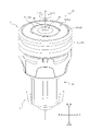
- FIG. 1 is a perspective view of an assembly according to one embodiment of the present disclosure
- FIG. Fig. 2 is an exploded perspective view of the assembly shown in Fig. 1 and showing a connector set according to one embodiment of the present disclosure
- Figure 2 is a top view of the assembly shown in Figure 1
- 4 is a cross-sectional view of the assembly shown in FIG. 1 taken along line I-I in FIG. 3
- FIG. 4 is a cross-sectional view of the assembly shown in FIG. 1 taken along line II-II of FIG. 3
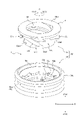
- FIG. 3 is an exploded perspective view of the conversion adapter shown in FIG. 2 and according to an embodiment of the present disclosure
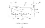
- FIG. 3 is a diagram showing a rotation control mechanism of the conversion adapter shown in FIG. 2
- FIG. 3 is a diagram showing a rotation control mechanism of the conversion adapter shown in FIG. 2;
- FIG. 3 is a cross-sectional view showing a state in which a luer lock first male connector portion conforming to ISO80369 of another medical connector is connected to the medical connector shown in FIG. 2.
- FIG. 2 is a cross-sectional view showing a state in which a second male connector portion of another medical connector that does not conform to ISO 80369 is connected to the assembly shown in FIG. 1;
- FIG. FIG. 10 is a perspective view of the assembly and the medical connector shown in FIG. 9 in a connected state;
- 3 is a view showing a modification of the medical connector shown in FIG. 2 to which the conversion adapter shown in FIG. 2 can be attached;
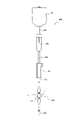
- FIG. 10B is a diagram showing an example of an infusion line including an assembly in which the conversion adapter shown in FIG. 2 is attached to the medical connector shown in FIG. 10B.
- FIG. 10B is a diagram showing an example of an infusion line including an
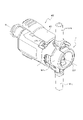
- FIG. 1 is a perspective view showing an assembly 100 as one embodiment of an assembly according to the present disclosure.
- FIG. 2 is an exploded perspective view of assembly 100 shown in FIG.
- FIG. 2 is a diagram showing a connector set 200.
- the assembly 100 includes a conversion adapter 1 as one embodiment of the conversion adapter according to the present disclosure and a medical connector 2.
- the medical connector 2 includes a female connector portion 2a connectable to a luer lock type male connector portion 300a (see FIG. 8) conforming to ISO80369.
- the male connector portion 300a (see FIG.
- the conversion adapter 1 can be attached to the female connector portion 2a of the medical connector 2. As shown in FIG. Here, the conversion adapter 1 and the medical connector 2 may be distributed as an assembly 100 in which the conversion adapter 1 is attached to the female connector portion 2a of the medical connector 2, as shown in FIG.
- the conversion adapter 1 and the medical connector 2 are distributed together as a connector set 200 in separate states in which the conversion adapter 1 is not attached to the female connector portion 2a of the medical connector 2. good too. Furthermore, the conversion adapter 1 and the medical connector 2 may be distributed separately.
- the conversion adapter 1 is attached to a female connector section 2a connectable to a luer lock first male connector section 300a (see FIG. 8) conforming to ISO80369.
- the female connector portion 2a is configured to be connectable to a luer lock first male connector portion 300a (see FIG. 8) conforming to ISO80369 by screwing in a state in which the conversion adapter 1 is not attached.
- the female connector portion 2a is configured to be connectable to a male connector portion 400a (see FIG. 9) that does not conform to ISO80369 by a predetermined lock mechanism in a state where the conversion adapter 1 is attached.
- the male connector portion 400a see FIG.
- the conversion adapter 1 replaces the female connector portion 2a connectable with the first male connector portion 300a (see FIG. 8) of the luer lock type conforming to ISO80369 with the second male connector portion 400a (see FIG. 9) not conforming to ISO80369. ) and an adapter that converts into a connectable state by a predetermined locking mechanism.
- FIG. 3 is a top view of the assembly 100 when the assembly 100 is viewed from the top surface 12a side of the elastic valve body 12.
- FIG. 4 is a cross-sectional view of assembly 100 taken along line II of FIG.
- FIG. 5 is a cross-sectional view of assembly 100 taken along line II-II of FIG.
- the medical connector 2 includes a female connector portion 2a connectable to a luer lock first male connector portion 300a (see FIG. 8) conforming to ISO80369.
- the female connector portion 2a can be connected to the first male connector portion 300a (see FIG. 8) by screwing.
- the female connector portion 2a includes at least a tubular portion 2a1.
- a male threaded portion 40 that can be screwed with a female threaded portion 302a (see FIG. 8) of a luer lock first male connector portion 300a (see FIG. 8) conforming to ISO80369 is formed on the outer surface of the cylindrical portion 2a1.
- an insertion opening 14 into which a first male luer portion 301 see FIG.
- the medical connector 2 includes a housing 11 and an elastic valve body 12 to which the housing 11 is attached.
- the female connector portion 2a of the present embodiment is composed of a cap 16 which is a part of the housing 11 and an elastic valve body 12, which will be described later. Details of the tubular portion 2a1 of the female connector portion 2a of the present embodiment will be described later.
- the housing 11 defines a hollow portion 13.
- the elastic valve body 12 is positioned in the hollow portion 13 .
- the hollow portion 13 has an insertion opening 14 into which a first male connector portion 300a (see FIG. 8) and a second male connector portion 400a (see FIG. 9) can be inserted from the outside, and a channel communicating with the insertion opening 14. 15.
- the elastic valve body 12 closes the insertion opening 14 in the hollow portion 13 .
- the term "channel communicating with the insertion opening” means not only a channel directly communicating with the insertion opening but also a channel communicating with the insertion opening via another space.
- the channel 15 of this embodiment is a channel directly connected to the insertion opening 14 .
- the housing 11 defines a channel 15 and a cap 16 defining an insertion opening 14 into which the first male connector portion 300a (see FIG. 8) and the second male connector portion 400a (see FIG. 9) are inserted from the outside. and a holder 17 that supports the cap 16 .
- the cap 16 includes a top cap 18 and a bottom cap 19.
- the elastic valve body 12 is compressed and sandwiched by a top cap 18 and a bottom cap 19 to fix its position in the hollow portion 13 , more specifically in the insertion opening 14 .
- the holder 17 is a member that partitions the channel 15 and supports the top cap 18 and the bottom cap 19 .
- both the top cap 18 and the bottom cap 19 contact the holder 17 and are directly supported by the holder 17 .
- the bottom cap 19 may be held by the top cap 18, and only the top cap 18 may be in contact with the holder 17 and directly supported.
- the top cap 18 may be held by the bottom cap 19, and only the bottom cap 19 may be in contact with the holder 17 and directly supported.
- Materials for the holder 17, the top cap 18 and the bottom cap 19 of the housing 11 include polyolefins such as polyethylene, polypropylene, and ethylene-propylene copolymer; ethylene-vinyl acetate copolymer (EVA); polyvinyl chloride; Polyvinylidene chloride; Polystyrene; Polyamide; Polyimide; Polyamideimide; Polycarbonate; Poly-(4-methylpentene-1); Ionomer; Acrylic resin; Styrene copolymer (AS resin); butadiene-styrene copolymer; polyester such as polyethylene terephthalate (PET), polybutylene terephthalate (PBT), polycyclohexane terephthalate (PCT); polyether; polyether ketone (PEK); Ether ether ketone (PEEK); Polyetherimide; Polyacetal (POM); Polyphenylene oxide; Modified polyphenylene oxide; Polysulfone; Various resin materials such
- the elastic valve body 12 is elastically deformed and can be opened and closed when the first male connector portion 300a (see FIG. 8) and the second male connector portion 400a (see FIG. 9) are attached to and detached from the medical connector 2. has a slit 20 in the Further, the elastic valve body 12 is arranged so as to close the insertion opening 14 defined by the top cap 18 and the bottom cap 19 . Specifically, the elastic valve body 12 is clamped by a clamping portion composed of a top cap 18 and a bottom cap 19 to fix its position in the insertion opening 14 .
- the elastic valve body 12 is molded and formed to be elastically deformable.
- materials for the elastic valve body 12 include natural rubber, isoprene rubber, butadiene rubber, styrene-butadiene rubber, nitrile rubber, chloroprene rubber, butyl rubber, acrylic rubber, ethylene-propylene rubber, hydrin rubber, urethane rubber, silicone rubber, Various rubber materials such as fluororubber, styrene, polyolefin, polyvinyl chloride, polyurethane, polyester, polyamide, polybutadiene, transpolyisoprene, fluororubber, chlorinated polyethylene, etc.
- a plastic elastomer may be mentioned, and one or more of these may be mixed.
- the female connector portion 2a of the medical connector 2 of this embodiment is composed of the top cap 18, the bottom cap 19, and the elastic valve body 12 sandwiched between the top cap 18 and the bottom cap 19. ing.
- the top cap 18 includes a substantially cylindrical hollow cylinder portion 36 and a flange portion 37 .
- the flange portion 37 extends radially from the end in the insertion direction A1 of the first male connector portion 300a (see FIG. 8) and the second male connector portion 400a (see FIG. 9), which is one side of the hollow cylindrical portion 36 in the axial direction. It protrudes outward in direction B.
- the first male connector portion 300a (see FIG. 8) and the second male connector portion 400a (see FIG. 9), which are on the other side in the axial direction of the hollow cylindrical portion 36, are removed.
- a planar upper end face 38 extending in a direction orthogonal to the insertion direction A1 and the withdrawal direction A2 is provided at the end in the direction A2.
- the upper end surface 38 defines one end in the removal direction A2 of the insertion opening 14 into which the first male connector portion 300a (see FIG. 8) and the second male connector portion 400a (see FIG. 9) are inserted from the outside.
- a circular rim 39 is included.
- a male threaded portion 40 is formed on the outer peripheral surface of the hollow cylindrical portion 36 to be screwed with the female threaded portion 302a (see FIG. 8) of the luer lock type first male connector portion 300a (see FIG. 8) conforming to ISO80369.
- the flange portion 37 is formed integrally with the hollow cylindrical portion 36 , and the top cap 18 is held by the holder 17 by engaging the flange portion 37 with the holder 17 described later.
- a locking projection 41 is provided near the edge 39 of the inner wall of the hollow cylindrical portion 36 and protrudes in the insertion direction A1.
- the locking projection 41 enters the annular groove formed in the outer edge of the top surface 12 a of the elastic valve body 12 and compresses the elastic valve body 12 together with the locking projection 45 of the bottom cap 19 .
- the bottom cap 19 includes a substantially cylindrical hollow tube portion 43 and a flange portion 44, similar to the top cap 18.
- the flange portion 44 protrudes outward in the radial direction B from the end portion of the hollow cylindrical portion 43 in the insertion direction A1.
- the end portion of the hollow cylindrical portion 43 in the withdrawal direction A2 enters the annular groove formed in the outer edge portion of the bottom surface 12b of the elastic valve body 12 described above, and moves into the elastic valve body 12 together with the locking projection 41 of the top cap 18. are compressed and sandwiched.
- the bottom cap 19 is ultrasonically bonded to the inner surface of the hollow cylindrical portion 36 of the top cap 18 and/or the lower surface of the flange portion 37 (the lower surface in FIGS. 4 and 5). held.
- the lower surface of the flange portion 44 of the bottom cap 19 (lower surface in FIGS. 4 and 5) is supported by a holder 17 which will be described later.
- the holder 17 supports the top cap 18 and the bottom cap 19, and partitions the channel 15 therein.
- the holder 17 of the present embodiment supports the top cap 18 and the bottom cap 19 by directly contacting them, the configuration is not limited to that described above.
- members in direct contact with each other in the top cap 18 and the bottom cap 19 are preferably bonded by, for example, ultrasonic bonding.
- the holder 17 of the present embodiment includes a luer lock first male connector portion conforming to ISO80369.
- the holder 17 of the present embodiment includes a substantially cylindrical tubular portion 46 formed with a female threaded portion 46a that can be screwed with the male threaded portion 40 of the female connector portion 2a of another medical connector or the like; and a male luer portion 47 provided in a hollow portion defined by the tubular portion 46 .
- the shape of the holder 17 of the medical connector 2 is not limited to the configuration of this embodiment.
- the medical connector 2 may, for example, be configured to include a holder 517 as shown in FIG. 10B.
- the holder 517 includes a substantially cylindrical holder main body 517a that partitions a hollow portion inside, and tubular upstream port portions 517b and downstream port portions 517c that protrude from the outer peripheral surface of the holder main body 517a.
- a hollow portion inside the holder main body 517a serves as part of a flow path from the upstream port portion 517b to the downstream port portion 517c.
- the female connector portion 2a of the medical connector 2 is composed of the cap 16 and the elastic valve body 12.
- the tubular portion 2a1 of the female connector portion 2a is composed of the hollow tubular portion 36 of the top cap 18 and the hollow tubular portion 43 of the bottom cap 19.
- the male screw portion 40 formed on the outer surface of the hollow cylindrical portion 36 of the top cap 18 is a female screw portion 302a (see FIG. 8) of the luer lock type first male connector portion 300a (see FIG. 8) conforming to ISO80369. ) can be screwed together.
- a luer lock type first male connector portion 300a conforming to ISO 80369 is inserted.
- a single male luer 301 is insertable from the outside.
- the medical connector 2 of this embodiment includes the housing 11 and the elastic valve body 12, and the female connector portion 2a is constituted by part of the housing 11 and the elastic valve body 12.
- the medical connector 2 is configured to include a luer lock type male connector portion conforming to ISO80369, such as the first male connector portion 300a (see FIG. 8) shown in this embodiment, and a connectable female connector portion 2a, Well, the specific number of members and the shape of members are not particularly limited.
- the female connector portion 2a may be, for example, a luer lock type female connector portion conforming to ISO80369.
- FIG. 6 is an exploded perspective view of the conversion adapter 1 shown in FIG. 2.
- FIG. 7A and 7B are diagrams showing the rotation control mechanism of the conversion adapter 1.
- the conversion adapter 1 can be attached to a female connector portion 2a connectable to a luer lock first male connector portion 300a (see FIG. 8) conforming to ISO80369.
- the conversion adapter 1 includes a female threaded portion 50 that can be screwed with the male threaded portion 40 of the female connector portion 2a.
- the conversion adapter 1 is connected to the female connector portion 2a by threaded connection by screwing the female threaded portion 50 with the male threaded portion 40 .
- the conversion adapter 1 is provided with a female threaded portion 50 that can be screwed into the male threaded portion 40 of the female connector portion 2a that can be connected to the first male connector portion 300a (see FIG. 8) of the luer lock type that conforms to ISO80369.
- the adapter 1 can be easily connected to the female connector portion 2a.
- the conversion adapter 1 has a locking portion 51 capable of locking the second male connector portion 400a (see FIG. 9) that does not conform to ISO80369.
- the locking portion 51 of this embodiment is configured by an annular groove 51a as a concave portion that can be engaged with the locking claw 402 (see FIG. 9) of the second male connector portion 400a (see FIG. 9). It is
- the medical device such as the medical connector 2 having the female connector portion 2a can be used as a non-ISO 80369 standard regardless of the difference in the shape of the portion other than the female connector portion 2a.
- the 2 male connector portion 400a (see FIG. 9) can be locked using a predetermined locking mechanism using the locking portion 51 of the conversion adapter 1.
- the conversion adapter 1 of this embodiment includes a tubular adapter main body 52 .
- the female threaded portion 50 of the conversion adapter 1 of this embodiment is formed on the inner surface of the adapter main body 52.
- the locking portion 51 of the conversion adapter 1 of this embodiment is formed on the outer surface of the adapter main body 52.
- the conversion adapter 1 can have a simple configuration.
- the conversion adapter 1 of this embodiment is composed only of the cylindrical adapter main body 52, it is not limited to this configuration.
- the conversion adapter 1 may be configured to include another portion in addition to the cylindrical adapter main body 52 .
- the axial direction of the cylindrical adapter main body 52 will be referred to as “axial direction A of the adapter main body 52" or simply “axial direction A”.
- the axial direction A of the adapter body 52 is substantially parallel to the insertion direction A1 and withdrawal direction A2 of the female connector portion 2a when the adapter body 52 is connected to the female connector portion 2a. Therefore, hereinafter, one side of the axial direction A will be referred to as the insertion direction A1, and the other side of the axial direction A will be referred to as the withdrawal direction A2.
- the radial direction of the circle around the central axis O of the adapter main body 52 is referred to as "radial direction B of the adapter main body 52" or simply "radial direction B".
- the circumferential direction around the central axis O of the adapter body 52 is referred to as "circumferential direction C of the adapter body 52" or simply “circumferential direction C”.
- the central axis O, the radial direction B, and the circumferential direction C of the adapter main body 52 correspond to the central axis, radial direction, Match each circumferential direction. Therefore, in the drawings, for convenience of explanation, the central axis of the tubular portion 2a1 of the female connector portion 2a is also denoted by “O”, the radial direction of the tubular portion 2a1 is also denoted by “B”, and the circumferential direction of the tubular portion 2a1 is also denoted by "B”.
- the code is "C”.
- the adapter main body 52 of this embodiment includes an inner cylindrical body 53 and an outer cylindrical body 54 .
- the inner tubular body 53 includes an inner tubular portion 53a having an internal threaded portion 50 formed therein.
- the outer cylindrical body 54 includes an outer cylindrical portion 54a positioned radially outwardly of the inner cylindrical portion 53a in the B direction and having the locking portion 51 formed on the outer surface thereof.
- the inner cylindrical body 53 of the present embodiment includes an inner cylindrical portion 53a having the internal thread portion 50 formed on the inner surface as described above, and an end portion of the inner cylindrical portion 53a in the removal direction A2. It has an annular flange portion 53b projecting outward in the radial direction B, and a plurality of projecting portions 53c projecting from the flange portion 53b in the insertion direction A1.
- a support projection 53a1 for supporting the outer cylinder 54 from the insertion direction A1 side is projected from the end of the inner cylinder portion 53a in the insertion direction A1.
- a plurality of support protrusions 53a1 are provided at positions spaced apart in the circumferential direction C, but the number and positions thereof are not particularly limited.
- the support projections 53a1 of the present embodiment sandwich the outer cylindrical body 54 in the axial direction A together with the flange portion 53b, thereby restricting relative movement of the outer cylindrical body 54 with respect to the inner cylindrical body 53 in the axial direction A.
- the relative movement of the outer cylindrical body 54 with respect to the inner cylindrical body 53 in the insertion direction A1 is such that the later-described flange portion 54b of the outer cylindrical body 54 contacts the support projection 53a1 of the inner cylindrical portion 53a of the inner cylindrical body 53. controlled by contact.
- relative movement of the outer cylinder 54 with respect to the inner cylinder 53 in the removal direction A2 is restricted by the contact of the outer cylinder portion 54a of the outer cylinder 54 with the flange portion 53b of the inner cylinder 53 .
- the inner cylindrical body 53 and the outer cylindrical body 54 of this embodiment can be connected in the axial direction A so as not to be separated from each other. Therefore, unintentional separation of the inner tubular body 53 and the outer tubular body 54 is suppressed, and operability for a medical worker using the conversion adapter 1 can be improved.
- the plurality of protrusions 53c are arranged at predetermined intervals in the circumferential direction C.
- the plurality of projecting portions 53c of this embodiment are arranged at four equal intervals in the circumferential direction C. As shown in FIG.
- Each projecting portion 53c is located outside in the radial direction B with respect to the inner cylindrical portion 53a.
- each protrusion 53c is arranged so as to be spaced outward in the radial direction B from the outer surface of the inner cylindrical portion 53a.
- the protrusion 53c constitutes a part of the rotation control mechanism of this embodiment (see FIGS. 7A and 7B).
- the inner cylindrical body 53 of this embodiment has a plurality of protrusions 53c, but the number is not particularly limited.
- the number of protrusions 53c of the inner cylindrical body 53 may be only one, or may be plural other than four.
- each projecting portion 53c of the present embodiment is configured by a rod-like projection projecting from the flange portion 53b in a direction inclined with respect to the insertion direction A1.
- the rod-like protrusion as the protrusion 53c of the present embodiment protrudes in a direction inclined with respect to the axial direction A from the flange 53b. Therefore, as shown in FIGS. 7A and 7B, a lower side surface 53c1, which is the side surface of the protrusion 53c on the insertion direction A1 side, and an upper side surface 53c2, which is the side surface of the protrusion 53c on the removal direction A2 side, It is composed of an inclined surface that is inclined with respect to Further, as shown in FIGS. 7A and 7B, the tip surface 53c3 of the protrusion 53c is configured by a plane substantially parallel to the axial direction A. As shown in FIG.
- Each projecting portion 53c can swing by being elastically deformed in the axial direction A with the base end connected to the flange portion 53b as a fulcrum.
- the rotation control mechanism of the present embodiment is such that the projection 53c of the inner cylinder 53 swings in the axial direction A according to the engagement relationship with the projection 54b1 of the outer cylinder 54. , restricts or permits relative rotation of the inner cylinder 53 and the outer cylinder 54 (see FIGS. 7A and 7B).
- the outer cylindrical body 54 includes the outer cylindrical portion 54a having the locking portion 51 formed on the outer surface as described above, and the outer cylindrical portion 54a protruding inward in the radial direction B from the end portion of the outer cylindrical portion 54a in the insertion direction A1. and an annular flange portion 54b.
- the locking portion 51 formed on the outer surface of the outer cylindrical portion 54a is the annular groove 51a as a recess extending over the entire circumferential direction C, as described above.
- the locking portion 51 is not limited to the annular groove 51a of this embodiment.
- the locking portion 51 may be composed of a plurality of recesses spaced apart in the circumferential direction C, for example.
- the locking portion 51 can be appropriately designed according to the specific shape of the second male connector portion 400a (see FIG. 9), and is not limited to a concave portion. It is preferable to form a concave portion that can be engaged with the locking claw 402 (see FIG. 9) of the male connector portion 400a (see FIG. 9). By doing in this way, it is easy to implement
- a stepped surface 54a1 for supporting the flange portion 53b of the inner tubular body 53 from the insertion direction A1 side is formed on the inner surface of the outer tubular portion 54a.
- the outer cylindrical portion 54a of the present embodiment has different inner diameters on the insertion direction A1 side and on the withdrawal direction A2 side.
- the stepped surface 54a1 of the present embodiment is an annular plane facing the removal direction A2 and connecting the portions of the inner surface of the outer cylindrical portion 54a having different inner diameters.
- the flange portion 53b which constitutes the end portion of the inner cylindrical body 53 in the withdrawal direction A2, is accommodated in the outer cylindrical portion 54a, and the inner cylindrical body 53 and the outer cylindrical body 54 are separated from each other.
- the inner cylindrical body 53 and the outer cylindrical body 54 are arranged in a state in which the outer cylindrical body 54 covers the outer side of the inner cylindrical body 53 in the radial direction B so that the inner cylindrical body 53 cannot be held from the outside in the radial direction B. can be concatenated. Therefore, it is possible to suppress the rotation of the inner cylindrical body 53 so as to detach from the female connector section 2a in a state where the inner cylindrical body 53 is screwed to the female connector section 2a. Details of this will be described later.
- a plurality of convex portions 54b1 are provided on the surface of the flange portion 54b on the withdrawal direction A2 side.
- the plurality of protrusions 54b1 are arranged in the circumferential direction C at predetermined intervals. Twelve convex portions 54b1 of the present embodiment are arranged at regular intervals in the circumferential direction C. As shown in FIG. Although the details will be described later, the convex portion 54b1 constitutes a part of the rotation control mechanism of the present embodiment (see FIGS. 7A and 7B).
- the outer cylindrical body 54 of this embodiment has a plurality of projections 54b1, but the number is not particularly limited. The number of protrusions 54b1 of the outer cylindrical body 54 may be only one, or may be plural other than twelve.
- each convex portion 54b1 of the present embodiment is provided on one side in the circumferential direction C with a plane substantially parallel to the axial direction A.
- a motion control surface 55a is provided.
- each convex portion 54b1 of the present embodiment includes a rotation permitting surface 55b formed of a plane inclined with respect to the axial direction A on the other side in the circumferential direction C.
- the convex portion 54b1 of the present embodiment is a substantially triangular protrusion having both side surfaces of the rotation restricting surface 55a and the rotation allowing surface 55b, but the shape thereof is particularly limited as long as the rotation control described below is possible. not.
- a rotation control mechanism is provided between the inner cylindrical body 53 and the outer cylindrical body 54 of the present embodiment.
- the rotation control mechanism regulates the rotation of the outer cylinder 54 relative to the inner cylinder 53 toward one side in the circumferential direction C.
- the rotation control mechanism allows the outer cylinder 54 to rotate relative to the inner cylinder 53 in the other circumferential direction C.
- loosening of the screw connection between the female connector portion 2 a of the medical connector 2 and the inner cylinder 53 due to the rotation of the outer cylinder 54 can be suppressed.
- the female threaded portion 50 of the inner cylindrical body 53 rotates in the tightening direction C1, which is one side of the circumferential direction C, with respect to the male threaded portion 40 of the female connector portion 2a. By screwing together, it is screwed to the medical connector 2 . Conversely, when the conversion adapter 1 and the medical connector 2 are screwed together, the female threaded portion 50 of the inner cylindrical body 53 is positioned on the other side in the circumferential direction C with respect to the male threaded portion 40 of the female connector portion 2a. , the screw connection between the conversion adapter 1 and the medical connector 2 is loosened.
- the rotation control mechanism restricts the rotation of the outer cylinder 54 relative to the inner cylinder 53 in the tightening direction C1. That is, when the outer cylindrical body 54 tries to rotate in the tightening direction C1 relative to the inner cylindrical body 53, the outer cylindrical body 54 is restricted from rotating by the inner cylindrical body 53 and does not rotate relatively. . Therefore, when connecting the conversion adapter 1 to the female connector portion 2a of the medical connector 2, the outer cylindrical body 54 is rotated in the tightening direction C1. As a result, the inner cylindrical body 53 and the outer cylindrical body 54 are rotated together by the rotation control mechanism, and the female threaded portion 50 of the inner cylindrical body 53 is screwed to the male threaded portion 40 of the female connector portion 2a.
- the rotation control mechanism controls the rotation of the outer cylindrical body 54 relative to the inner cylindrical body 53 in the loosening direction C2. allow. That is, when the outer cylindrical body 54 tries to rotate in the loosening direction C2 relative to the inner cylindrical body 53, the outer cylindrical body 54 is not restricted by the inner cylindrical body 53 and rotates relatively. It is possible. Therefore, when the outer cylinder 54 is rotated in the loosening direction C2 while the conversion adapter 1 is connected to the female connector portion 2a of the medical connector 2, the outer cylinder 54 is rotated by the rotation control mechanism. It idles with respect to the inner cylindrical body 53 .
- the rotation control mechanism of this embodiment is a ratchet mechanism.
- the rotation control mechanism of the present embodiment is composed of the projection 53c of the inner cylinder 53 and the projection 54b1 of the outer cylinder 54. As shown in FIG.
- the tip surface 53c3 of the protrusion 53c of the inner cylinder 53 and the rotation restricting surface 55a of the protrusion 54b1 of the outer cylinder 54 are aligned in the circumferential direction. They are arranged so as to face each other at C.
- FIG. 7A shows a state in which the outer cylindrical body 54 is about to rotate relative to the inner cylindrical body 53 in the tightening direction C1 (leftward direction in FIGS. 7A and 7B).
- the rotation restricting surface 55a of the projection 54b1 is pushed by the protrusion of the inner cylindrical body 53. 53c, and presses the inner cylindrical body 53 in the tightening direction C1. That is, by attempting to rotate the outer cylinder 54 relative to the inner cylinder 53 in the tightening direction C1 (the left direction in FIG. 7A), the inner cylinder 53 and the outer cylinder 54 are rotated together. be able to.
- FIG. 7B shows a state in which the outer cylindrical body 54 is about to rotate relative to the inner cylindrical body 53 in the loosening direction C2 (rightward direction in FIGS. 7A and 7B).
- the rotation restricting surface 55a of the projection 54b1 moves toward the tip of the protrusion 53c of the inner cylinder 53. It does not hit the surface 53c3.
- the lower side surface 53c1 of the protrusion 53c slides on the rotation-permitting surface 55b of the protrusion 54b1, so that the base end connected to the flange 53b is used as a fulcrum to elastically deform and swing in the removal direction A2 ( See arrows in FIG. 7B).
- the projecting portion 53c can get over the projecting portion 54b1. That is, even if the outer cylinder 54 is rotated relative to the inner cylinder 53 in the loosening direction C2 (rightward direction in FIGS. 7A and 7B), the inner cylinder 53 does not rotate together with the outer cylinder 54. Therefore, the outer cylindrical body 54 idles with respect to the inner cylindrical body 53 .
- the rotation control mechanism is not limited to the configuration of this embodiment.
- the inner cylinder 53 has the protrusion 53c and the outer cylinder 54 has the protrusion 54b1.
- the shapes of the projecting portion 53c and the projecting portion 54b1 are not limited to the shapes of the present embodiment.
- the mechanism need not be a ratchet mechanism. However, by using the ratchet mechanism as in the present embodiment, the above rotation control can be easily realized with a simple configuration.
- the female threaded portion 50 of the adapter main body 52 of the present embodiment is such that the tip of the cylindrical portion 2a1 of the female connector portion 2a is aligned with one end of the adapter main body 52 in the axial direction A.
- the male screw portion 40 of the female connector portion 2a can be screwed together until it is flush with the inner edge of the end on the withdrawal direction A2 side, which is the inner edge of the female connector portion 2a. That is, the upper end surface 38 forming the tip of the cylindrical portion 2a1 of the female connector portion 2a of the present embodiment is in a state where the conversion adapter 1 is connected to the female connector portion 2a (see FIGS. 1, 4, and 5).
- the tip of the tubular portion 2a1 of the female connector portion 2a is exposed from the conversion adapter 1, so that the tip of the tubular portion 2a1 can be easily cleaned, and the wiping performance of the tubular portion 2a1 can be improved. can be enhanced.
- the female threaded portion 50 of the adapter body 52 may be configured to be screwed with the male threaded portion 40 of the female connector portion 2a until the cylindrical portion 2a1 of the female connector portion 2a passes through the adapter body 52 in the axial direction A. By doing so, it is possible to improve the wiping performance of the cylindrical portion 2a1 as described above.
- FIG. 8 is a cross-sectional view showing a state in which the female connector portion 2a of the medical connector 2 is connected to the luer lock first male connector portion 300a of another medical connector 300 conforming to ISO80369.
- the first male connector portion 300a of the medical connector 300 includes a first male luer portion 301 and a cylindrical portion 302 surrounding the first male luer portion 301 radially outwardly.
- a female threaded portion 302a is formed on the inner surface of the tubular portion 302 .
- the conversion adapter 1 is not connected to the female connector portion 2a of the medical connector 2.
- the first male luer portion 301 of the first male connector portion 300a is inserted from the outside into the insertion opening 14 of the tubular portion 2a1 of the female connector portion 2a.
- the male screw portion 40 of the tubular portion 2a1 of the female connector portion 2a is screwed into the female screw portion 302a of the first male connector portion 300a, thereby connecting the female connector portion 2a and the first male connector portion 300a.
- FIG. 9 shows a state in which the conversion adapter 1 is connected to the female connector portion 2a of the medical connector 2, and the second male connector portion 400a of another medical connector 400, which does not conform to ISO 80369, is connected. It is a sectional view showing.
- the second male connector portion 400a of the medical connector 400 includes a second male luer portion 401 and a locking claw 402 located radially outside the second male luer portion 401. As shown in FIG. 9, the second male connector portion 400a of the medical connector 400 includes a second male luer portion 401 and a locking claw 402 located radially outside the second male luer portion 401. As shown in FIG. 9, the second male connector portion 400a of the medical connector 400 includes a second male luer portion 401 and a locking claw 402 located radially outside the second male luer portion 401.
- the second male luer portion 401 of the second male connector portion 400a is inserted from the outside into the insertion opening 14 of the tubular portion 2a1 of the female connector portion 2a.
- the tip projection 402a of the locking claw 402 of the second male connector portion 400a into the annular groove 51a of the locking portion 51 of the conversion adapter 1 connected to the female connector portion 2a.
- the female connector portion 2a to which the conversion adapter 1 is connected and the second male connector portion 400a are connected.
- the use of the conversion adapter 1 facilitates the attachment operation of the male connector section to the female connector section 2a. More specifically, as shown in FIG. 8, when connecting the first male connector portion 300a to the female connector portion 2a, the first male connector portion 300a is placed relatively in the circumferential direction of the tubular portion 2a1 of the female connector portion 2a. It is screwed by rotating it. On the other hand, as shown in FIG. 9, when connecting the second male connector portion 400a to the female connector portion 2a, the second male connector portion 400a is brought close to the insertion direction A1 of the female connector portion 2a, Insert the two-male luer part 401 into the insertion opening 14 .
- the locking claw 402 of the second male connector portion 400a engages with the annular groove 51a as the locking portion 51 of the conversion adapter 1,
- the connection between the connector portion 2a and the second male connector portion 400a is completed. That is, only by moving the second male connector portion 400a relative to the female connector portion 2a in the insertion direction A1, the female connector portion 2a and the second male connector portion 400a can be engaged with the locking claws 402 and the annular groove 51a. It can be connected in a predetermined locked state by
- the second male connector portion that can be connected in the locked state is not limited to the configuration shown in FIG. That is, the second male connector portion may have a different shape that does not comply with ISO80369.
- 10A and 10B are diagrams showing two types of medical connectors 2 having a female connector portion 2a with different holder shapes. 10A and 10B show a state in which the medical connector 400 shown in FIG. 9 is connected to two types of medical connectors 2.
- FIG. The medical connector 2 shown in FIG. 10A is similar in construction to those shown in FIGS.
- the medical connector 2 shown in FIG. 10B includes a holder 517 having a substantially cylindrical holder body 517a, an upstream port portion 517b and a downstream port portion 517c.
- the second male connector portion 400a that does not conform to ISO 80369 can be locked using a predetermined locking mechanism using the locking portion 51 of the conversion adapter 1. .
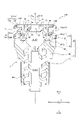
- An infusion line 600 includes an infusion tube 603 and a clamp 604 between an infusion bag 601 containing a liquid such as a drug solution and an indwelling needle 602 inserted into a patient's vein or the like. It is configured.
- the medical connector 2 is provided on the infusion line 600 , and enables a luer lock first male connector portion 300 a (see FIG. 8 ) conforming to ISO80369 to be connected to the infusion line 600 .
- FIG. 11 shows a state (assembly state) in which the conversion adapter 1 is attached to the female connector portion 2a (see FIG. 2, etc.) of the medical connector 2.
- FIG. 11 shows the infusion line 600 including the medical connector 2 shown in FIG. 10B, the infusion line 600 may include the medical connector 2 shown in FIG. 2 and the like.
- the conversion adapter, connector set, and assembly according to the present disclosure are not limited to the specific configurations shown in the above-described embodiments, and various modifications, changes, and combinations are possible without departing from the scope of the claims.
- the connector set 200 shown in FIG. 2 may include other medical instruments such as a medical tube 605 shown in FIG. 11 in addition to the conversion adapter 1 and the medical connector 2 . That is, the connector set 200 may be an infusion set including the conversion adapter 1 and the medical connector 2 .
- the assembly 100 has a configuration in which the conversion adapter 1 is attached to the medical connector 2, but the assembly 100 is not limited to this configuration.
- the assembly 100 may be configured to include the conversion adapter 1 and the female connector portion 2a to which the conversion adapter 1 is attached, and the medical device including the female connector portion 2a is limited to the medical connector 2. do not have.
- the present disclosure relates to conversion adapters, connector sets and assemblies.
- Conversion adapter 2 Medical connector 2a: Female connector part 2a1: Cylindrical part 11: Housing 12: Elastic valve body 12a: Top surface 12b of elastic valve body: Bottom surface of elastic valve body 13: Hollow part 14: Insertion opening 15 : Flow path 16: Cap 17: Holder 18: Top cap 19: Bottom cap 20: Slit 36: Top cap hollow cylindrical portion 37: Top cap flange 38: Top cap upper end surface 39: Top surface Cap top edge 40: Top cap male thread 41: Top cap locking projection 43: Bottom cap hollow cylinder 44: Bottom cap flange 45: Bottom cap locking projection 46: Holder Cylindrical portion 46a: female threaded portion 47 of holder: male luer portion 50: female threaded portion 51: locking portion 51a: annular groove (recess) 52: Adapter main body 53: Inner cylindrical body 53a: Inner cylindrical portion 53a1: Support projection 53b: Flange portion 53b1: Upper surface of flange portion 53c: Protruding portion (part of rotation control mechanism) 53c1: lower
Landscapes
- Health & Medical Sciences (AREA)
- Heart & Thoracic Surgery (AREA)
- Pulmonology (AREA)
- Engineering & Computer Science (AREA)
- Anesthesiology (AREA)
- Biomedical Technology (AREA)
- Hematology (AREA)
- Life Sciences & Earth Sciences (AREA)
- Animal Behavior & Ethology (AREA)
- General Health & Medical Sciences (AREA)
- Public Health (AREA)
- Veterinary Medicine (AREA)
- Infusion, Injection, And Reservoir Apparatuses (AREA)
Priority Applications (2)
| Application Number | Priority Date | Filing Date | Title |
|---|---|---|---|
| JP2023502090A JP7792391B2 (ja) | 2021-02-24 | 2021-12-14 | 変換アダプタ、コネクタセット及び組立体 |
| US18/363,355 US20230372691A1 (en) | 2021-02-24 | 2023-08-01 | Conversion adapter, connector set, and assembly |
Applications Claiming Priority (2)
| Application Number | Priority Date | Filing Date | Title |
|---|---|---|---|
| JP2021027894 | 2021-02-24 | ||
| JP2021-027894 | 2021-02-24 |
Related Child Applications (1)
| Application Number | Title | Priority Date | Filing Date |
|---|---|---|---|
| US18/363,355 Continuation US20230372691A1 (en) | 2021-02-24 | 2023-08-01 | Conversion adapter, connector set, and assembly |
Publications (1)
| Publication Number | Publication Date |
|---|---|
| WO2022180991A1 true WO2022180991A1 (ja) | 2022-09-01 |
Family
ID=83048026
Family Applications (1)
| Application Number | Title | Priority Date | Filing Date |
|---|---|---|---|
| PCT/JP2021/046119 Ceased WO2022180991A1 (ja) | 2021-02-24 | 2021-12-14 | 変換アダプタ、コネクタセット及び組立体 |
Country Status (3)
| Country | Link |
|---|---|
| US (1) | US20230372691A1 (https=) |
| JP (1) | JP7792391B2 (https=) |
| WO (1) | WO2022180991A1 (https=) |
Families Citing this family (1)
| Publication number | Priority date | Publication date | Assignee | Title |
|---|---|---|---|---|
| USD1037408S1 (en) * | 2022-03-03 | 2024-07-30 | Crisol Technology Co., Ltd | Water filter |
Citations (6)
| Publication number | Priority date | Publication date | Assignee | Title |
|---|---|---|---|---|
| US20080312640A1 (en) * | 2007-06-14 | 2008-12-18 | Sabin Corporation | Modified luer fittings for feeding tube adapter |
| US20170014616A1 (en) * | 2015-07-15 | 2017-01-19 | Neomed, Inc. | Enteral adaptor couplings |
| JP2017144184A (ja) * | 2016-02-19 | 2017-08-24 | 株式会社ジェイ・エム・エス | アダプタ |
| JP2018513748A (ja) * | 2015-04-23 | 2018-05-31 | スミスズ メディカル エーエスディー,インコーポレイティド | 改ざん防止コネクタ/アダプタ装置及び関連する方法 |
| US20190336743A1 (en) * | 2016-11-10 | 2019-11-07 | N.V. Nutricia | Enteral feeding adapter |
| JP2020512150A (ja) * | 2017-03-31 | 2020-04-23 | ベクトン ディキンソン フランス | コネクタを薬物送達デバイスに接続するためのアダプタ |
Family Cites Families (10)
| Publication number | Priority date | Publication date | Assignee | Title |
|---|---|---|---|---|
| FR2996141B1 (fr) * | 2012-09-28 | 2023-04-07 | Vygon | Systeme de connexion medicale anti-devissage |
| KR102315224B1 (ko) * | 2013-12-11 | 2021-10-20 | 가부시끼가이샤 제이엠에스 | 수형 커넥터 |
| US10201693B2 (en) * | 2015-08-06 | 2019-02-12 | Hsi-Chin Tsai | Closed male luer |
| WO2017051536A1 (ja) * | 2015-09-24 | 2017-03-30 | テルモ株式会社 | 医療用コネクタ |
| GB201608603D0 (en) * | 2016-05-16 | 2016-06-29 | Medical Device Creations Ltd | Improved fluid line connector device |
| JP2018130495A (ja) * | 2017-02-17 | 2018-08-23 | テルモ株式会社 | 医療用コネクタ及び輸液セット |
| US10918848B1 (en) * | 2017-06-16 | 2021-02-16 | Ronald D. Russo | High flow enternal connector system |
| EP3689412B1 (en) * | 2017-12-26 | 2024-03-27 | Terumo Kabushiki Kaisha | Medical connector |
| US20220288378A1 (en) * | 2019-09-03 | 2022-09-15 | Elcam Medical A.C.A.L. | Breakaway intra-medical tubing connector assembly |
| US20230264008A1 (en) * | 2021-09-17 | 2023-08-24 | Joseph P. Schultz | Enteral Feeding System |
-
2021
- 2021-12-14 WO PCT/JP2021/046119 patent/WO2022180991A1/ja not_active Ceased
- 2021-12-14 JP JP2023502090A patent/JP7792391B2/ja active Active
-
2023
- 2023-08-01 US US18/363,355 patent/US20230372691A1/en active Pending
Patent Citations (6)
| Publication number | Priority date | Publication date | Assignee | Title |
|---|---|---|---|---|
| US20080312640A1 (en) * | 2007-06-14 | 2008-12-18 | Sabin Corporation | Modified luer fittings for feeding tube adapter |
| JP2018513748A (ja) * | 2015-04-23 | 2018-05-31 | スミスズ メディカル エーエスディー,インコーポレイティド | 改ざん防止コネクタ/アダプタ装置及び関連する方法 |
| US20170014616A1 (en) * | 2015-07-15 | 2017-01-19 | Neomed, Inc. | Enteral adaptor couplings |
| JP2017144184A (ja) * | 2016-02-19 | 2017-08-24 | 株式会社ジェイ・エム・エス | アダプタ |
| US20190336743A1 (en) * | 2016-11-10 | 2019-11-07 | N.V. Nutricia | Enteral feeding adapter |
| JP2020512150A (ja) * | 2017-03-31 | 2020-04-23 | ベクトン ディキンソン フランス | コネクタを薬物送達デバイスに接続するためのアダプタ |
Also Published As
| Publication number | Publication date |
|---|---|
| JPWO2022180991A1 (https=) | 2022-09-01 |
| JP7792391B2 (ja) | 2025-12-25 |
| US20230372691A1 (en) | 2023-11-23 |
Similar Documents
| Publication | Publication Date | Title |
|---|---|---|
| AU2016206252B2 (en) | Connector assembly, male connector, and female connector | |
| US8641012B2 (en) | Medical connector | |
| JP6204200B2 (ja) | コネクタ | |
| US12569662B2 (en) | Medical connector | |
| US20130072893A1 (en) | Connector and connector assembly | |
| US20130144246A1 (en) | Connector and connector assembly | |
| JP5678510B2 (ja) | 医療用コネクタ | |
| WO2012017865A1 (ja) | 三方活栓ユニット、逆止弁及び流動性物質移送装置 | |
| US20170368325A1 (en) | Connector and medical device set | |
| JP2005261931A (ja) | コネクタ | |
| JP2024045522A (ja) | 雄コネクタ | |
| WO2022163311A1 (ja) | 医療用コネクタ | |
| US20230372691A1 (en) | Conversion adapter, connector set, and assembly | |
| WO2018174265A1 (ja) | 医療用コネクタ | |
| WO2016051759A1 (ja) | メスコネクタ、オスコネクタ及びコネクタ接続体 | |
| JP2005110842A (ja) | 接続器具 | |
| US20210402168A1 (en) | Medical device | |
| JP5574175B2 (ja) | 医療用コネクタ | |
| JP7389062B2 (ja) | 医療用コネクタ | |
| JP7041570B2 (ja) | 接続保持具セット | |
| WO2021124727A1 (ja) | 医療用コネクタ | |
| WO2021186871A1 (ja) | コネクタセット及びメスコネクタ |
Legal Events
| Date | Code | Title | Description |
|---|---|---|---|
| 121 | Ep: the epo has been informed by wipo that ep was designated in this application |
Ref document number: 21928084 Country of ref document: EP Kind code of ref document: A1 |
|
| ENP | Entry into the national phase |
Ref document number: 2023502090 Country of ref document: JP Kind code of ref document: A |
|
| NENP | Non-entry into the national phase |
Ref country code: DE |
|
| 122 | Ep: pct application non-entry in european phase |
Ref document number: 21928084 Country of ref document: EP Kind code of ref document: A1 |