WO2018174265A1 - 医療用コネクタ - Google Patents
医療用コネクタ Download PDFInfo
- Publication number
- WO2018174265A1 WO2018174265A1 PCT/JP2018/011846 JP2018011846W WO2018174265A1 WO 2018174265 A1 WO2018174265 A1 WO 2018174265A1 JP 2018011846 W JP2018011846 W JP 2018011846W WO 2018174265 A1 WO2018174265 A1 WO 2018174265A1
- Authority
- WO
- WIPO (PCT)
- Prior art keywords
- cylinder member
- distal end
- valve body
- inner cylinder
- elastic valve
- Prior art date
Links
Images


Definitions
- This disclosure relates to a medical connector.
- an infusion line is generally formed by connecting an infusion tube, various medical devices, and the like.
- a liquid such as a chemical solution to be administered to a patient is injected into the chemical solution bag, it is necessary to connect the chemical solution bag to a syringe or the like.
- a female connector or a male connector as a medical connector is used to detachably connect different members.
- Patent Document 1 a housing that divides a hollow portion, a first valve body that is movably disposed at a distal end of the hollow portion and closes the housing, a cannula extending in the hollow portion, and a hollow portion
- a delivery device as a male connector comprising: a biasing member that biases the first valve body toward the distal end.
- the first valve body when the first valve body is pressed from the distal end side to the proximal end side by the second valve body of the receiver device as a female connector connectable to the delivery device, the first valve body The tip of the cannula penetrates the first valve body and the second valve body, and the tip of the cannula enters the housing of the receiver device.
- Patent Document 1 discloses a configuration in which the communication state between the delivery device and the receiver device via the cannula is maintained by screw connection between the housing of the delivery device and the housing of the receiver device, but the screw connection is loosened. When this occurs, the cannula of the delivery device may be removed from the housing of the receiver device and the communication state may be released. For this reason, it is desirable that the screw connection between the delivery device as the male connector and the receiver device as the female connector is difficult to loosen.
- a closed male connector (hereinafter referred to as “closed male connector”) that closes the flow path so that liquid does not leak to the outside when the connection with the female connector is released, such as the delivery device described in Patent Document 1. ) Is usually designed to maintain a stable connection with a dedicated female connector. However, a closed male connector is desired as a medical connector that can maintain a stable connection state even with a lock-type female connector conforming to ISO 80369-7 (2016) that is widely distributed.
- an object of the present disclosure is to provide a medical connector having a configuration capable of realizing screw coupling that is difficult to loosen even with a lock-type female connector conforming to ISO 80369-7.
- a medical connector covers a flow path tube portion that can be inserted into an insertion opening of a lock-type female connector conforming to ISO 80369-7, and a radial periphery of the flow path tube portion.
- a connection cylinder portion having a female thread portion that can be screwed into a tip flange of the female connector, and a closed configuration that covers an opening on the distal end side of the flow channel of the flow channel tube portion and the opening in the connection cylinder portion.
- An elastic valve body that can change its form between an open configuration and an open configuration, wherein the female threaded portion is screwed into the distal end flange so that the elastic valve body contacts the edge of the insertion opening of the female connector.
- a trough is provided that sandwiches the tip flange in a contacted state.
- the trough includes a sandwiching portion having a trough diameter smaller than a maximum rotation outer diameter defined by a rotation locus of the tip flange, and a distal end side from the sandwiching portion.
- a non-clamping portion having a valley diameter greater than or equal to the maximum rotation outer diameter, and the distal end side of the trough portion is configured only from the non-clamping portion. Has been.
- the valley diameter of the non-clamping portion gradually increases from the proximal end side toward the distal end side.
- the valley diameter of the sandwiching portion is gradually increased from the proximal end side toward the distal end side.
- the screw height at the position adjacent to the sandwiching portion in the crest portion of the female screw portion is smaller than the protruding length of the tip flange.
- a holding cylinder part is provided in the connection cylinder part and holds the elastic valve body therein, and the elastic valve body is formed at a distal end of the holding cylinder part.
- an inner cylinder member including the connection cylinder portion, and a housing including the flow path pipe portion and holding the inner cylinder member movably in the axial direction of the inner cylinder member
- the elastic valve body is capable of changing a form between the closed form and the open form in accordance with the movement of the inner cylinder member in the axial direction with respect to the housing. It is provided so that it can project from the distal end of the housing, and the projectable length is equal to or greater than the movable length in the axial direction of the inner cylinder member relative to the housing.
- the housing includes a holder member provided with the flow channel tube portion, and an outer cylinder attached to the holder member in a state of surrounding the radial direction of the flow channel tube portion.
- the outer cylinder member includes a locking portion that locks the inner cylinder member at a predetermined position spaced from the holder member, and the inner cylinder member is locked to the locking portion. It is movable in the axial direction with respect to the housing from a first position to a second position that contacts the holder member.
- a spirally extending groove is formed on one of the outer wall of the inner cylinder member and the inner wall of the outer cylinder member, and the outer wall of the inner cylinder member and the outer cylinder member On the other side of the inner wall, a convex portion that moves in the groove by moving the inner cylinder member in the circumferential direction relative to the outer cylinder member is formed.
- a medical connector having a configuration capable of realizing a screw connection that is difficult to loosen even with a lock-type female connector that conforms to ISO 80369-7.
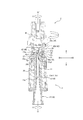
- FIG. 1 is a side view showing a closed male connector 1 as an embodiment of a medical connector according to the present invention and a female connector 2 connectable to the closed male connector 1.
- FIG. 2 is a cross-sectional view taken along the line II of FIG.
- the closed male connector 1 and the female connector 2 shown in FIGS. 1 and 2 each show a single state before being connected to each other.
- the one end side that is the downstream side (upper side in FIG. 1) of the liquid such as the chemical solution in the infusion line is the “distal end” side
- the liquid in the infusion line The other end side that is the upstream side of the flow path (lower side in FIG. 1) is referred to as the “proximal end” side.
- the closed male connector 1 includes a housing 10, an inner cylinder member 20, and an elastic valve body 30.
- the housing 10 is provided with a flow path pipe part 11.
- the channel tube portion 11 can be inserted into the insertion opening 42 c of the female connector 2.
- the inner cylinder member 20 is held with respect to the housing 10 so as to be movable in a direction parallel to the central axis O of the inner cylinder member 20 (hereinafter simply referred to as “axial direction A”).
- the inner cylinder member 20 includes a connection cylinder portion 21.
- the connecting tube portion 21 includes a female screw portion 21 a that covers the periphery of the flow path tube portion 11 in the radial direction B and can be screwed into the distal end flange 47 of the female connector 2.
- the elastic valve body 30 has a form between the closed form that covers the opening 11a1 on the distal end side of the flow path 11a of the flow path pipe part 11 and the open form that opens the opening 11a1 in the connection cylinder part 21. It can change. Specifically, a slit 32 a is formed in the elastic valve body 30 of the present embodiment, and the closed form of the present embodiment is a state in which the distal end of the flow path tube portion 11 is covered with the elastic valve body 30. . Moreover, the open form of this embodiment is the state which the front-end
- the female connector 2 is a lock-type female connector that complies with 2016 ISO 80369-7. As shown in FIGS. 1 and 2, the female connector 2 includes a housing 40 and an elastic valve body 50.
- the housing 10 of the closed male connector 1 is referred to as a “first housing 10” for convenience of explanation.
- the housing 40 of the connector 2 is referred to as a “second housing 40”.
- the elastic valve body 30 of the closed male connector 1 is referred to as “first elastic valve”.
- the elastic valve body 50 of the female connector 2 is described as a “second elastic valve body 50”.
- the second housing 40 defines a hollow portion 41.
- One end of the hollow portion 41 is an insertion opening 42 c into which the flow path tube portion 11 of the closed male connector 1 can be inserted. That is, the flow path tube portion 11 of the closed male connector 1 is inserted into the hollow portion 41 through the insertion opening 42c.
- the hollow portion 41 includes a holding space 41a in which the second elastic valve body 50 is held, and a flow path 41b that communicates with the holding space 41a.
- the second housing 40 includes a tip flange 47 that can be screwed with the female screw portion 21 a of the connection tube portion 21 of the closed male connector 1.
- the second housing 40 includes a cap 42 and a holder 43
- the hollow portion 41 includes a holding space 41 a defined by the cap 42 and a flow path defined by the cap 42 and the holder 43. 41b.
- the tip flange 47 is formed on the outer wall of the cap 42.
- the front end flange 47 of this embodiment constitutes a part of the thread 46 a of the male thread portion 46 formed on the outer wall of the cap 42. Details of the tip flange 47 will be described later (see FIGS. 2 and 5).
- the second elastic valve body 50 is located in the hollow portion 41 of the second housing 40 and closes the hollow portion 41. Specifically, as described above, the second elastic valve body 50 is positioned in the holding space 41a defined by the cap 42 in the hollow portion 41, and is compressed by being sandwiched by the cap 42 from the top surface 50a and the bottom surface 50b. It is pinched by being made into the state which was made.
- the second elastic valve body 50 is formed with a slit 51 into which the flow path pipe portion 11 of the closed male connector 1 can be inserted.
- the inner cylinder member 20 including the connection cylinder portion 21 of the closed male connector 1 is moved in the axial direction A with respect to the first housing 10 of the closed male connector 1 in the contact state.
- the flow path pipe part 11 of the closed male connector 1 can be moved relative to the first elastic valve body 30 in the axial direction A. Therefore, the distal end of the flow path tube portion 11 can be moved so as to penetrate the first elastic valve body 30. As a result, the flow path tube portion 11 can enter the hollow portion 41 of the female connector 2. Details of this connection operation will be described later (see FIGS. 6 and 7).
- the female screw portion 21a includes a trough portion 29a that sandwiches the tip flange 47 in the above-described contact state. Therefore, compared to a configuration in which the front end flange is not sandwiched in the same contact state, the front end flange 47 is less likely to rotate with respect to the female screw portion 21a due to an increase in frictional force. That is, it is possible to make it difficult to loosen the screw connection between the tip flange 47 and the female screw portion 21a. Details of this will be described later (see FIGS. 8 and 9).
- the closed male connector 1 of the present embodiment includes the first housing 10, the inner cylinder member 20, and the first elastic valve body 30. Details of each member will be described below.
- the first housing 10 includes a holder member 12 and an outer cylinder member 13.
- the holder member 12 protrudes toward the proximal end side from the flange portion 14 that protrudes in the radial direction B from the above-described flow channel tube portion 11, the proximal end of the flow channel tube portion 11, A connecting portion 15 that can be connected to a medical instrument such as a medical tube, and an annular protruding portion that is provided on the distal end side from the flange portion 14 so as to surround the outside in the radial direction B of the flow channel tube portion 11. 16.
- the flow path pipe portion 11 extends in the direction parallel to the central axis of the outer cylinder member 13 in the outer cylinder member 13. That is, the direction parallel to the central axis of the flow path tube portion 11 is substantially the same as the direction parallel to the central axis of the outer cylinder member 13. Further, as shown in FIG. 2, the direction parallel to the central axis of the flow path tube portion 11 and the direction parallel to the central axis of the outer cylindrical member 13 are substantially the same as the axial direction A of the inner cylindrical member 20 described later. It is. In other words, as shown in FIG.
- the center axis of the flow path tube portion 11, the center axis of the outer cylinder member 13, and the center axis O of the inner cylinder member 20 of the present embodiment substantially coincide with each other. Therefore, hereinafter, for convenience of explanation, the direction parallel to the central axis of the flow path tube portion 11, the direction parallel to the central axis of the outer cylindrical member 13, and the axial direction A of the inner cylindrical member 20 are all referred to as “axial direction A”. It describes.
- the radial directions of the flow path pipe part 11, the outer cylinder member 13, and the inner cylinder member 20 are also substantially coincident. Furthermore, the circumferential direction of each of the flow path pipe portion 11, the outer cylinder member 13, and the inner cylinder member 20 is also substantially the same. Therefore, hereinafter, for the convenience of explanation, the radial direction of the flow path tube portion 11, the outer cylinder member 13, and the inner cylinder member 20 are all referred to as “radial direction B”. For convenience of explanation, the circumferential direction of the channel tube portion 11, the outer cylinder member 13, and the inner cylinder member 20 are all described as “circumferential direction C”.
- the flow path tube section 11 defines a flow path 11 a inside.
- the flow path 11 a of the flow path pipe part 11 extends in the axial direction A.
- An opening 11 a 1 penetrating in the radial direction B is formed at the distal end portion of the flow channel tube portion 11.
- the distal end of the channel tube part 11 is closed.
- the proximal end of the flow channel tube part 11 is not closed but is opened, and an opening 11 a 2 is formed at the proximal end of the flow channel tube unit 11. That is, the flow path 11a of the flow path pipe part 11 extends from the proximal end side opening 11a2 of the flow path pipe part 11 to the distal end side opening 11a1.
- the flow path pipe portion 11 is inserted into the insertion opening 42 c of the female connector 2 when connected to the female connector 2. Details of this will be described later (see FIG. 7).
- the flange part 14 is supporting the proximal end of the 1st elastic valve body 30 mentioned later in the position of the radial direction B of the flow-path pipe part 11 at the position. More specifically, the flange portion 14 is in contact with the proximal end of the first elastic valve body 30 at a position between the flow channel tube portion 11 and the protruding portion 16 in the radial direction B, so that the first elastic valve The body 30 is supported.
- the connecting portion 15 is a cylindrical portion projecting from the flange portion 14 toward the proximal end side, and can be connected to a medical tube, for example, by fitting a medical tube as a medical instrument.
- the cylindrical connection portion 15 defines a hollow portion 15a whose distal end communicates with the flow channel 11a of the flow channel tube portion 11 and whose proximal end is open to the outside.
- the connecting portion 15 of this embodiment shown in FIG. 2 constitutes a female connector portion conforming to 2016 ISO 80369-7. Therefore, not only the connection of the medical tube by the fitting described above, but also a locking male connector compliant with ISO 80369-7 of 2016 can be connected to the connection portion 15 of the present embodiment. Furthermore, the connection part 15 of this embodiment can also be connected to the distal end of a closed connector having the same shape as the closed male connector 1.
- the annular projecting portion 16 contacts the inner cylinder member 20 and restricts the movement of the inner cylinder member 20 toward the proximal end side in the axial direction A. Specifically, the convex portion 21b formed on the outer wall of the inner cylindrical member 20 abuts on the distal end, which is the tip of the protruding portion 16, so that the inner cylindrical member 20 moves toward the proximal end side. Be regulated. Details of this will be described later (see FIGS. 4 and 7).
- the outer cylinder member 13 which will be described later is supported by the flange portion 14 in a state where the proximal end portion thereof is externally fitted to the annular projecting portion 16.
- the outer cylinder member 13 is fitted to the protrusion 16 so as to be in close contact with the outer surface of the annular protrusion 16, and the outer cylinder member 13 is protruded together with the flange portion 14 or instead of the flange portion 14. It is good also as a structure supported by the part 16.
- the length of the protruding portion 16 in the axial direction A is longer than the length of the flow path tube portion 11 in the axial direction A and the length of the outer cylinder member 13 in the axial direction A. short.
- the flow path pipe part 11 and the outer cylinder member 13 extend to the distal end side with respect to the protruding part 16. More specifically, the flow path tube portion 11 extends to the distal end side with respect to the outer cylinder member 13.
- the annular projecting portion 16 is used.
- the protrusion may be configured by a plurality of protrusions that protrude from the flange portion 14 and are arranged along the circumferential direction C.
- the protrusion may be a rod-shaped protrusion extending in the axial direction A, or may be a curved plate-shaped protrusion having a cross section orthogonal to the axial direction A having an arc shape.
- Examples of the material of the holder member 12 include polyolefins such as polyethylene, polypropylene, and ethylene-propylene copolymer; ethylene-vinyl acetate copolymer (EVA); polyvinyl chloride; polyvinylidene chloride; polystyrene; polyamide; polyimide; Polyimide (polymethyl 4-pentene-1); ionomer; acrylic resin; polymethyl methacrylate; acrylonitrile-butadiene-styrene copolymer (ABS resin); acrylonitrile-styrene copolymer (AS resin); butadiene- Styrene copolymer; Polyester such as polyethylene terephthalate (PET), polybutylene terephthalate (PBT), polycyclohexane terephthalate (PCT); polyether; polyether ketone ( EK); polyetheretherketone (PEEK); polyetherimide; polyacetal (POM); polyphenylene
- the holder member 12 is integrally formed of a single material.
- the holder member 12 may have at least the above-described flow path pipe part 11, flange part 14, connection part 15, and protrusion part 16. It may be formed by assembling a plurality of members.
- the outer cylinder member 13 is attached to the holder member 12 in a state of surrounding the circumference of the flow path pipe portion 11 in the radial direction B.
- the outer cylinder member 13 has a substantially cylindrical shape, and is concentric with the flow path pipe part 11 in a cross section orthogonal to the axial direction A outside the radial direction B with respect to the flow path pipe part 11.
- the flow passage tube portion 11 is surrounded so as to have a shape.
- the outer cylindrical member 13 surrounds the protrusion 16 so as to be concentric with the annular protrusion 16 in a cross section orthogonal to the axial direction A on the outer side in the radial direction B with respect to the protrusion 16. It is out.
- the proximal end portion of the outer cylinder member 13 is attached to the flange portion 14 by ultrasonic welding, adhesion, or the like.
- the inner cylinder member 20 is fitted in the outer cylinder member 13. Specifically, the inner cylinder member 20 is held in the outer cylinder member 13 so as to be movable in the axial direction A with respect to the outer cylinder member 13.
- a female screw portion 13a is formed on the inner wall of the outer cylinder member 13 of the present embodiment.
- the inner wall of the outer cylinder member 13 is formed with a groove 13a1 extending in a spiral shape.
- the convex part 21b is formed in the outer wall of the inner cylinder member 20 mentioned later (refer FIG. 4). This convex part 21b is movable along the above-mentioned groove 13a1.
- the convex portion 21b can be moved in the groove 13a1 along the extending direction of the groove 13a1. .
- the inner cylinder member 20 can be moved in the axial direction A with respect to the outer cylinder member 13. Details of this will also be described later (see FIG. 4).
- FIG. 3 is a sectional view of the closed male connector 1 taken along the line II-II in FIG.
- the peripheral wall of the outer cylinder member 13 is provided with a deformable portion 18 that is elastically deformable in the radial direction B and is configured by a portion surrounded by a notch-shaped gap 17. More specifically, in the present embodiment shown in FIG. 3, gaps 17 are formed at four positions at equal intervals in the circumferential direction C, and are surrounded by the gaps 17 in the outer cylinder member 13. A deformed portion 18 is formed by the portion. In other words, in the present embodiment, the deforming portions 18 are arranged for each central angle of about 90 degrees, and a total of four deforming portions 18 are provided.
- the proximal end side is continuous with the peripheral wall of the outer cylindrical member 13, and the distal end side is not continuous with the peripheral wall of the outer cylindrical member 13 with the gap 17 interposed therebetween.
- both sides of the deformable portion 18 in the circumferential direction C are not continuous with the peripheral wall of the outer cylindrical member 13 with the gap 17 interposed therebetween.
- the deformed portion 18 having such a configuration can be elastically deformed in the radial direction B on the distal end side with respect to the proximal end side.
- the distal end of the deformable portion 18 is provided with a protrusion 18a that protrudes inward in the radial direction B.
- the protrusion 18 a in the deformed portion 18 of the outer cylindrical member 13 is a locking portion that can lock the inner cylindrical member 20 at a predetermined position away from the holder member 12.
- the deformable portion 18 can be elastically deformed in the radial direction B.
- the protrusion 18 a can change the position in the radial direction B by elastic deformation in the radial direction B of the deformation portion 18.
- the protrusion 18a in the radial direction B is changed.
- the protrusion 18a as the locking portion shown in FIG. 2 is in a state at the locking position. Details of this operation will be described later (see FIGS. 6 and 7).
- Examples of the material of the outer cylinder member 13 include materials similar to the materials that can be used as the holder member 12 described above.
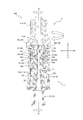
- the inner cylinder member 20 includes a connection cylinder part 21 in which an internal thread part 21 a is formed on the inner wall, and a position closer to the proximal end side than the internal thread part 21 a of the inner wall of the connection cylinder part 21.
- a first annular flange portion 22 projecting inward in the radial direction B, and a holding tubular portion 23 positioned in the connecting tube portion 21 and projecting from the inner edge of the first annular flange portion 22 toward the distal end side in the axial direction A From the inner edge portion of the first annular flange portion 22 and projecting toward the proximal end side in the axial direction A, the narrow tube portion 24 having a smaller outer diameter than the connecting tube portion 21, and the proximal end of the narrow tube portion 24
- a second annular flange portion 25 projecting outward in the radial direction B and a proximal end tubular portion 26 projecting from the outer edge of the second annular flange portion 25 toward the proximal end side in the axial direction A are provided.
- FIG. 4 is a view showing a state in which the inner cylinder member 20 is separated from the closed male connector 1. Specifically, in FIG. 4, the separated inner cylinder member 20 is shown in a perspective view, and the remaining portion of the closed male connector 1 is shown in a cross-sectional perspective view. As shown in FIG. 4, the connection cylinder part 21, the thin cylinder part 24, and the proximal end cylinder part 26 have a substantially cylindrical shape. And the outer peripheral surface of the inner cylinder member 20 is constricted in the position of the thin cylinder part 24, and the annular groove 24a extended in the circumferential direction C is formed.
- non-connection state In the state before connection shown in FIG. 2 (hereinafter, referred to as “non-connection state”), the first annular flange portion 22, the thin tubular portion 24, the second annular flange portion 25, and the base of the inner cylinder member 20.
- the end cylinder part 26 is fitted in the outer cylinder member 13.
- the connecting cylinder part 21 and the holding cylinder part 23 of the inner cylinder member 20 are distal to the outer cylinder member 13, that is, distal to the first housing 10. It protrudes to the end side.
- a protrusion 18 a as a locking portion of the outer cylinder member 13 is fitted in the annular groove 24 a formed on the outer wall of the inner cylinder member 20. That is, the protrusion 18a is in the locking position. Therefore, the inner cylinder member 20 cannot move to the proximal end side in the axial direction A with respect to the outer cylinder member 13 unless the protrusion 18a is moved from the locking position to the locking release position.
- a force of a predetermined value or more acts on the proximal end side in the axial direction A with respect to the inner cylindrical member 20, the protrusion 18a moves from the locking position to the locking release position. Yes.
- a convex portion 21 b is formed on the outer wall of the inner cylinder member 20. More specifically, the convex portion 21 b is formed on the outer wall of the proximal end cylindrical portion 26 of the inner cylindrical member 20. The convex portion 21 b is movable in the spiral groove 13 a 1 of the female screw portion 13 a formed on the inner wall of the outer cylinder member 13. Thereby, the inner cylinder member 20 can move in the axial direction A with respect to the outer cylinder member 13.
- the two convex portions 21 b are provided at positions facing each other in the radial direction B. Further, two spiral grooves 13a1 of the outer cylinder member 13 are also provided so as to correspond to the two convex portions 21b.
- the holding cylinder part 23 and the thin cylinder part 24 hold the first elastic valve body 30 therein.
- the holding cylinder portion 23 and the narrow cylinder portion 24 define an accommodation space 27 that accommodates a distal end portion 32 (described later) of the first elastic valve body 30.
- An annular protrusion 28 that protrudes inward in the radial direction B is formed on the inner wall that defines the accommodation space 27.
- the annular protrusion 28 is recessed with respect to the distal end portion 32 of the first elastic valve body 30, and prevents the distal end portion 32 from falling out of the accommodation space 27.
- the first elastic valve body 30 protrudes from a distal end opening 23 a formed at the distal end of the holding cylinder portion 23.
- Examples of the material of the inner cylinder member 20 include the same materials that can be used as the holder member 12 described above.
- the first elastic valve body 30 covers the flow path pipe portion 11. Specifically, the first elastic valve body 30 of the present embodiment closes the bellows tube portion 31 that can be elastically deformed so as to be folded in the axial direction A and the distal end side of the hollow portion of the bellows tube portion 31. As described above, a cylindrical tip portion 32 continuous to the bellows tube portion 31 and a flange portion 33 protruding outward in the radial direction B at the position of the distal end portion of the bellows tube portion 31 are provided.
- the proximal end of the bellows tube portion 31 is in contact with the flange portion 14 of the holder member 12 of the first housing 10.
- the distal end portion 32 is held in an accommodation space 27 defined by the holding cylinder portion 23 and the thin cylinder portion 24 of the inner cylinder member 20.
- the flange portion 33 is in contact with the second annular flange portion 25 of the inner cylinder member 20 in a state where the distal end portion 32 is accommodated in the accommodation space 27. Thereby, the front-end
- the annular protrusion 28 is formed on the inner wall that defines the accommodation space 27. Therefore, the tip end portion 32 is difficult to fall off to the proximal end side.
- the first elastic valve body 30 includes the protruding portion 34 protruding from the distal end opening 23a.
- the tip end surface 34a which is the end surface on the distal end side of the protruding portion 34 of the present embodiment, has a convex curved surface.
- the protrusion 34 has an outer diameter D5 (see FIG. 8) larger than the diameter D4 (see FIG. 8) of the insertion opening 42c of the female connector 2. With such a configuration, the entire edge portion 42 c 1 of the insertion opening 42 c of the female connector 2 can be easily covered with the protruding portion 34 when connected to the female connector 2. Details will be described later (see FIGS. 8 and 9).
- the front end surface 34a of the projecting portion 34 of the present embodiment is configured by one curved surface having an arc shape in the cross-sectional view of FIG. 2, but only the periphery of the slit 32a is a convex curved surface. May be.
- the distal end portion of the flow path tube portion 11 including the opening 11 a 1 on the distal end side is located on the distal end side in the axial direction A by the tip portion 32 of the first elastic valve body 30. And the outer side in the radial direction B is covered. Further, the slit 32a is also closed. That is, the 1st elastic valve body 30 shown in FIG. 2 has shown the closed form which covers opening 11a1.
- the bellows cylinder portion 31 is elastically deformed so as to be compressed. Accordingly, the distal end portion of the flow channel tube portion 11 including the opening 11a1 on the distal end side penetrates the distal end portion 32 in the axial direction A through the slit 32a of the distal end portion 32 of the first elastic valve body 30. . That is, the first elastic valve body 30 is in an open form in which the opening 11a1 is opened. As described above, the first elastic valve body 30 of the present embodiment can change its form between the closed form and the open form as the inner cylinder member 20 moves in the axial direction A with respect to the first housing 10. .
- the first elastic valve body 30 of the present embodiment is configured to include a bellows cylinder portion 31 and a tip portion 32, but a closed configuration and an opening covering the opening 11a1 on the distal end side of the flow channel 11a of the flow channel tube portion 11. If it is a structure which can change a form between the open forms which open
- the first elastic valve body 30 preferably has a Shore A hardness of 10 to 70, more preferably a Shore A hardness of 20 to 50.
- Shore A hardness When the hardness is smaller than the Shore A hardness 10, when the pressure in the flow path 11a increases, a fluid such as a chemical solution may leak to the outside. If the hardness is greater than Shore A hardness 70, the contact of the female connector 2 connected to the first elastic valve body 30 with the second elastic valve body 50 may be insufficient, and the connected female connector 2 When extracted, a fluid such as a chemical solution may leak out.
- the hardness of the first elastic valve body 30 is Shore A hardness 20 or more and 50 or less, it is possible to ensure suitable adhesion with the female connector 2, and when the connected female connector 2 is removed. In addition, it is possible to more reliably suppress the leakage of fluid such as a chemical solution to the outside.
- the first elastic valve body 30 is molded and formed to be elastically deformable.
- the material of the first elastic valve body 30 include natural rubber, isoprene rubber, butadiene rubber, styrene-butadiene rubber, nitrile rubber, chloroprene rubber, butyl rubber, acrylic rubber, ethylene-propylene rubber, hydrin rubber, urethane rubber, and silicone.
- Various rubber materials such as rubber and fluoro rubber, styrene, polyolefin, polyvinyl chloride, polyurethane, polyester, polyamide, polybutadiene, trans polyisoprene, fluoro rubber, chlorinated polyethylene, etc.
- Various thermoplastic elastomers can be mentioned, and a material obtained by mixing one or more of these may be used.
- the first elastic valve body 30 may be formed of different materials or the same material.
- the second housing 40 includes the cap 42 and the holder 43 that supports the cap 42.
- the cap 42 includes a cylindrical portion 42 a that partitions the holding space 41 a that houses the second elastic valve body 50 in the hollow portion 41, and a flange that is provided on the distal end portion of the cylindrical portion 42 a and is supported on the holder 43. Part 42b. More specifically, the cap 42 of the present embodiment includes a top cap 44 and a bottom cap 45. Both the top cap 44 and the bottom cap 45 have a hat shape including a cylindrical portion and a flange portion, and the cap 42 overlaps the top cap 44 and the bottom cap 45 and ultrasonically welds both contact surfaces thereof. It is formed by joining by. That is, the cylindrical portion 42 a of the cap 42 is configured by the cylindrical portions in which the top cap 44 and the bottom cap 45 are overlapped. Further, the flange portion 42 b of the cap 42 is configured by the flange portions in which the top surface cap 44 and the bottom surface cap 45 are overlapped with each other.
- the second elastic valve body 50 is compressed and sandwiched from the top surface 50a side and the bottom surface 50b side by the top surface cap 44 and the bottom surface cap 45 and positioned in the hollow portion 41, more specifically, in the holding space 41a. Is fixed. Through the slit 51 formed in the second elastic valve body 50, the flow path pipe portion 11 of the closed male connector 1 can be inserted from the outside into the hollow portion 41 defined by the second housing 40.
- FIG. 5 is a view of the female connector 2 as viewed from the top surface 48 side, which is the end surface of the cap 42 on the proximal end side. As shown in FIG. 5, an insertion opening 42 c is formed in the top surface 48 of the cap 42. The flow path pipe portion 11 of the closed male connector 1 is inserted into the hollow portion 41 through the insertion opening 42c (see FIG. 7).
- connection complete state A state in which the flow path pipe portion 11 of the closed male connector 1 is inserted into the hollow portion 41 of the female connector 2 to complete the connection between the closed male connector 1 and the female connector 2 (hereinafter referred to as “connection complete state”).
- the flow path tube portion 11 is not compressed inward in the radial direction B by the edge portion 42c1 that partitions the insertion opening 42c. That is, in the connection completion state, the outer diameter of the portion of the flow path tube portion 11 at the position of the insertion opening 42c is smaller than the diameter of the edge portion 42c1. Details of the connection completion state will be described later (see FIG. 7).
- a male screw portion 46 is formed on the outer surface of the cylindrical portion 42 a of the cap 42.
- the screw thread 46a of the male screw part 46 extends in a spiral manner to the position of the proximal end on the outer surface of the cylindrical part 42a, and the proximal end part of the screw thread 46a is a locking type conforming to ISO 80369-7.
- the front end flange 47 whose size is defined as a female connector is configured.
- the front end flange 47 of the present embodiment is formed integrally with the screw thread 46a as a part of the screw thread 46a of the male screw part 46.
- the "tip flange whose dimensions are defined as a lock-type female connector conforming to ISO 80369-7" as used herein refers to two positions at the end in the axial direction A and opposite to the radial direction B.
- This flange is provided, and the maximum diameter (maximum length) in the radial direction B between the two flanges is specified as 7.73 to 7.83 mm, and is perpendicular to the one radial direction that is the maximum diameter.
- the width of each flange in one radial direction is defined as 3.4 to 3.5 mm.
- the distal end flange 47 of the present embodiment has a maximum diameter W1 in the radial direction B of 7.83 mm (dimensional tolerance ⁇ 0.005 to 0 mm).
- the width W2 of each flange in another radial direction orthogonal to the maximum radial direction is 3.5 (dimensional tolerance ⁇ 0.01 to 0 mm).
- the holder 43 supports the cap 42.
- the holder 43 surrounds the male luer portion 43a that defines the flow path 41b that communicates with the holding space 41a that is defined by the cap 42, and the outer periphery in the radial direction B of the male luer portion 43a, and the internal thread portion 43b1 is formed on the inner surface.
- Examples of the material of the holder 43, the top cap 44, and the bottom cap 45 of the second housing 40 include the same materials as those that can be used as the holder member 12 of the closed male connector 1 described above.
- the second housing 40 of the present embodiment is configured to include the holder 43, the top cap 44, and the bottom cap 45, but is not limited to this configuration.
- the holder 43 and the bottom cap 45 of the present embodiment are single. It is good also as a single member shape
- any of the holder 43, the top cap 44, and the bottom cap 45 of the present embodiment may be formed by a combination of a plurality of members.
- the 2nd housing 40 is not restricted to the structure shown by this embodiment, For example, you may comprise from 1 member or 2 members, and may comprise from 4 members or more.
- the second elastic valve body 50 is a circular flat disk-like valve body having a substantially circular outer shape when viewed from the top surface 50a side.
- the second elastic valve body 50 is sandwiched by the second housing 40 by sandwiching the top surface 50a and the bottom surface 50b, and the position in the hollow portion 41 is fixed.
- the second elastic valve body 50 has a slit 51 at the center when viewed from the top surface 50a side.
- the slit 51 opens and closes when the second elastic valve body 50 is elastically deformed when the male connector is inserted into and removed from the hollow portion 41.
- the second elastic valve body 50 is sandwiched between the top surface 50a and the bottom surface 50b by the second housing 40 at the position of the peripheral edge located radially outside the central portion where the slit 51 is formed. .
- the second elastic valve body 50 is also molded and formed to be elastically deformable.
- the material similar to the material which can be utilized as the 1st elastic valve body 30 of the closed male connector 1 mentioned above can be mentioned, for example.
- the hardness of the second elastic valve body 50 is preferably set such that the second elastic valve body 50 ensures an appropriate elastic force.
- the hardness of the second elastic valve body 50 is a hardness that can be elastically deformed so as to open the slit 51 when a male luer part conforming to ISO 80369-7 is inserted into the hollow part 41.
- the male luer part in close contact with the outer wall of the male luer part and has a hardness capable of realizing a liquid-tight connection state.
- the hardness is set so as to be restored in the second housing 40 so that the slit 51 is closed when the male luer part conforming to ISO 80369-7 is removed from the hollow part 41.
- the hardness of the second elastic valve body 50 is not particularly limited as long as it maintains such performance, but in the present embodiment, the hardness is 20 to 60 ° (A hardness).
- the male luer portion 43a of the holder 43 of the female connector 2 conforms to ISO80369-7 and has a 6/100 tapered shape.
- the female connector 2 includes the second elastic valve body 50, but a female connector that does not have the second elastic valve body 50 may be used.
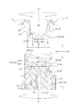
- FIG. 6 is a cross-sectional view showing a state in the middle of connecting the closed male connector 1 and the female connector 2.
- FIG. 7 is a cross-sectional view showing a state in which the connection of the closed male connector 1 and the female connector 2 is further advanced from the state of FIG. 6 and the connection of the closed male connector 1 and the female connector 2 is completed. More specifically, FIG. 6 shows a contact state in which the first elastic valve body 30 of the closed male connector 1 is in contact with the edge portion 42c1 of the insertion opening 42c of the female connector 2, but the flow path tube portion 11 is female.
- FIG. 7 shows a contact state, and the flow path pipe portion 11 of the closed male connector 1 passes through the first elastic valve body 30 and the second elastic valve body 50 and flows through the female connector 2.
- a connection completion state is shown in which the connection with the path 41b is completed.
- a connector connector 300 is constituted by the closed male connector 1 and the female connector 2.
- the closed male connector 1 and the female connector 2 are moved closer to the axial direction A from the non-connected state shown in FIG. 2, and the female connector 2 is rotated clockwise (see the white arrow in FIG. 2) relative to the closed male connector 1.
- the male screw portion 46 including the front end flange 47 of the female connector 2 can be screwed into the female screw portion 21a of the closed male connector 1.
- the central axis O of the closed male connector 1 and the central axis O ′ of the female connector 2 are substantially coincident with each other.
- the contact region 60 does not need to be formed so as to include the entire front end surface 34a of the protrusion 34 of the first elastic valve body 30. Further, the contact region 60 does not need to be formed so as to include the entire top surface 50a of the second elastic valve body 50. That is, it is only necessary that at least the portions of the front end surface 34a and the top surface 50a through which the flow path tube portion 11 passes are in contact with each other to form a contact region. In the present embodiment, it is only necessary that the periphery of the slit 32a of the first elastic valve body 30 and the periphery of the slit 51 of the second elastic valve body 50 are in contact with each other to form the contact region 60.
- the projection 18a as the locking portion remains in the locked position fitted in the annular groove 24a from the non-connected state shown in FIG. 2 to the connection halfway state shown in FIG. . That is, the inner cylinder member 20 is rotated in the circumferential direction C with respect to the first housing 10 until the connection state (see FIG. 6) in which the contact state is realized from the non-connection state (see FIG. 2). It does not move in the axial direction A.
- the contact state in this embodiment is also a state in which the distal end of the connection tube portion 21 of the inner tube member 20 is in contact with the flange portion 42b of the cap 42 of the female connector 2.
- the male screw portion 46 and the female screw portion 21a are screwed together. It is good also as a mark which can confirm from the outside that the state was implement
- the distal end of the holding cylinder portion 23 is the female. It is good also as a structure which contact
- a convex portion 21b formed on the outer wall of the inner cylinder member 20 moves along the spiral groove 13a1 formed in the inner wall of the outer cylinder member 13 from the distal end side toward the proximal end side.
- the inner cylinder member 20 can be moved to the proximal end side in the axial direction A relative to the outer cylinder member 13. More specifically, the inner cylinder member 20 is moved from the first position (see FIGS. 2 and 6) locked to the protrusion 18a as the locking portion to the second position (see FIG. 7) contacting the holder member 12. Until the first housing 10 moves in the axial direction A.
- the flow path tube portion 11 remains in the first elastic valve body 30 while maintaining the contact state in which the first elastic valve body 30 of the closed male connector 1 is in contact with the edge portion 42c1 of the insertion opening 42c of the female connector 2. From the state where the opening 11a1 is closed by the first elastic valve body 30 without passing through the first elastic valve body 30 (see FIG. 6), the flow passage tube portion 11 penetrates the first elastic valve body 30 and the opening 11a1 is the first elastic valve body. The form can be changed from 30 to a released state. More specifically, when the inner cylinder member 20 moves to the proximal end side with respect to the outer cylinder member 13 from the connection intermediate state shown in FIG. 11 penetrates the first elastic valve body 30 and the second elastic valve body 50. As a result, as shown in FIG. 7, a connection completion state is realized in which the flow path 11 a of the flow path pipe portion 11 of the closed male connector 1 is in fluid-tight communication with the flow path 41 b of the female connector 2.
- the inner cylinder member 20 is The convex portion 21b (see FIG. 4) moves along the spiral groove 13a1 so as to be separated from the first housing 10 in the axial direction A integrally with the female connector 2 while maintaining the contact state. Move in the direction.
- the inner cylinder member 20 changes from the connection completion state shown in FIG. 7 to the connection halfway state shown in FIG. That is, the flow path pipe part 11 is removed from the second elastic valve body 50 through the contact region 60.
- the first elastic valve body 30 changes the form from the open form in which the opening 11a1 on the distal end side of the flow path 11a of the flow path pipe part 11 is opened to the closed form in which the opening 11a1 is covered. In this manner, the connection completion state shown in FIG. 7 is shifted to the connection intermediate state shown in FIG.
- connection completion state shown in FIG. 7 the first elastic valve body 30 is compressed in the axial direction A by the movement of the inner cylinder member 20 toward the proximal end side, and the inner cylinder member 20 is moved to the distal end by the restoring force. Energized to the side. Therefore, when changing from the connection completion state shown in FIG. 7 to the connection halfway state shown in FIG. 6, compared with the case of changing from the connection halfway state shown in FIG. 6 to the connection completion state shown in FIG. The state can be changed by adding. Then, when the annular groove 24a of the inner cylinder member 20 reaches the position of the protrusion 18a of the outer cylinder member 13, the protrusion 18a is fitted into the annular groove 24a and becomes the locking position.
- the female connector 2 When the female connector 2 is further rotated counterclockwise relative to the closed male connector 1 (in the opposite direction of the white arrow in FIG. 6) from the intermediate connection state shown in FIG. Since the movement is restricted by the outer cylindrical member 13 of the first housing 10 via the screw connection, the screw connection between the male threaded portion 46 of the female connector 2 and the female threaded portion 21a of the inner cylindrical member 20 of the closed male connector 1 is performed. It turns in the direction of loosening. As a result, the female connector 2 moves in a direction (upward in FIG. 6) that is separated from the inner cylinder member 20 in the axial direction A. More specifically, the protrusion 18a has a flat surface substantially parallel to the radial direction on the end face on the proximal end side.
- the inner cylinder member 20 that is going to advance toward the distal end side is not pushed outward in the radial direction B, and remains in the locking position.
- the contact between the top surface 50a of the second elastic valve body 50 of the female connector 2 and the distal end surface 34a of the first elastic valve body 30 of the closed male connector 1 is released. That is, the contact area 60 is eliminated. Further, the contact between the tip end surface 34a of the projecting portion 34 and the entire circumferential direction C of the edge portion 42c1 of the insertion opening 42c is also released.
- the closed male connector 1 and the female connector 2 at the time of connection, the abutment where the distal end surface 34a of the projecting portion 34 and the entire circumferential direction C of the edge portion 42c1 of the insertion opening 42c abut.
- the flow path tube portion 11 can be inserted into the hollow portion 41 of the female connector 2 while maintaining the state.
- the flow path tube portion 11 can be removed from the hollow portion 41 of the female connector 2 while maintaining the contact state even when the connection is released. Therefore, the closed male connector 1 and the female connector 2 can be connected in a fluid-tight manner.
- the top surface 50a of the second elastic valve body 50 of the female connector 2 and the first elastic valve body 30 of the closed male connector 1 are connected at the time of connection.
- the flow path tube portion 11 can be inserted into the hollow portion 41 of the female connector 2.
- the flow path tube portion 11 can be removed from the hollow portion 41 of the female connector 2 through the contact region 60 even when the connection is released. it can. In this manner, the flow path tube portion 11 can be inserted and removed through the contact region 60. Therefore, when the closed male connector 1 and the female connector 2 are changed from the connection completion state (see FIG.
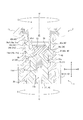
- FIG. 8 is an enlarged cross-sectional view in which portions of the female screw portion 21a and the male screw portion 46 in FIG. 2 are enlarged.
- FIG. 9 is an enlarged cross-sectional view in which the female screw portion 21a and the male screw portion 46 in FIG. 7 are enlarged.
- the female screw portion 21 a is screwed with a male screw portion 46 including a tip flange 47 formed integrally with the end portion on the proximal end side, and the first elastic valve body 30 is connected to the female connector 2.
- the contact state is in contact with the edge portion 42c1 of the insertion opening 42c.
- the trough part 29a of the internal thread part 21a has pinched
- the valley 29a of the present embodiment compresses the two tip flanges 47 with a pressure equal to or greater than a predetermined value toward the inside in the radial direction B, that is, the opposing direction of the two tip flanges 47. Therefore, the frictional resistance between the valley portion 29a and the tip flange 47 can be increased as compared with a state in which the two are simply in contact with each other without being pressed against each other. That is, the loosening and release of the screwing between the female screw portion 21a and the tip flange 47 can be made even more difficult to occur.
- the valley portion 29a of the present embodiment shown in FIG. 8 includes a sandwiching portion 29a1 having a valley diameter D2 smaller than the maximum rotation outer diameter D1 defined by the rotation locus of the tip flange 47. At least a part of the sandwiching portion 29a1 is located on the outer side in the radial direction B with respect to the distal end flange 47 in the contact state shown in FIG. That is, the tip flange 47 is compressed toward the inner side in the radial direction B by the sandwiching portion 29a1 in the contact state shown in FIG. As shown in FIG.
- the “maximum rotation outer diameter D1” of the distal end flange 47 is the outermost portion in the radial direction B among the distal end flanges 47 whose dimensions are defined as a lock-type female connector conforming to ISO 80369-7.
- the point Q positioned at the position means the diameter of a locus formed by rotating around the central axis of the cylindrical portion 42a coinciding with the central axis O 'of the entire female connector 2. That is, the length is equal to the maximum diameter W1 shown in FIG.
- the front end flange 47 of this embodiment is pressed inward in the radial direction B by the sandwiching portion 29a1 and is compressed and deformed.
- the valley portion 29a of the present embodiment is located on the distal end side with respect to the sandwiching portion 29a1, and has a valley diameter D3 equal to or larger than the maximum rotation outer diameter D1 of the tip flange 47.
- the non-pinch portion 29a2 is provided.
- the distal end side rather than the clamping part 29a1 is comprised only from the non-clamping part 29a2.
- the valley diameter D3 of the non-clamping portion 29a2 is gradually increased from the proximal end side toward the distal end side. Therefore, the front end flange 47 is likely to be accommodated in the valley portion 29a when the front end flange 47 and the internal thread portion 21a are started to be screwed together. That is, it becomes easy to realize the engagement between the tip flange 47 and the valley portion 29a of the female screw portion 21a, which is a trigger for starting screwing, and the operability at the time of connection can be further improved.
- the valley diameter D2 of the sandwiching portion 29a1 is also gradually increased from the proximal end side toward the distal end side.
- the female screw portion 21a includes a mountain portion 29b formed of a screw thread in addition to the above-described valley portion 29a formed of a portion between adjacent screw threads. And as shown in FIG. 8, the screw height H1 in the position adjacent to the clamping part 29a1 of the trough part 29a is smaller than the protrusion height H2 of the front-end
- the screw height H1 means the height in the radial direction B with respect to the position where the screw thread adjacent to the sandwiching portion 29a1 in the axial direction A becomes the minimum outer diameter of the sandwiching portion 29a1 adjacent to the sandwiching portion 29a1.
- the protruding height H2 of the tip flange 47 means the maximum height in the radial direction B of the tip flange 47 with respect to the circumferential surface at a position adjacent to the tip flange 47 in the cylindrical portion 42a where the tip flange 47 is formed. is doing.
- the first elastic valve body 30 includes the protruding portion 34 protruding from the distal end opening 23a.
- the protrusion part 34 of this embodiment has the outer diameter D5 larger than the diameter D4 of the insertion opening 42c of the female connector 2.
- the outer diameter D5 of the protruding portion 34 means the outer diameter of the outer edge of the protruding portion 34 when the protruding portion 34 is viewed from the distal end surface 34a side.
- the distal end flange 47 is formed as a part of the proximal end side of the male screw portion 46 provided on the outer wall of the cylindrical portion 42a.
- a lock-type female connector that conforms to ISO 80369-7.
- the tip flange 47 may be formed at the position of the proximal end of the outer wall of the cylindrical portion 42a.
- the peak diameter of the peak part 29b is also changed from the proximal end side to the distal end side in the same manner as the valley diameter D2 of the sandwiched part 29a1 of the valley part 29a and the valley diameter D3 of the non-squeezed part 29a2.
- it is the structure which increases gradually toward this, it is not restricted to this structure, It is good also as a constant structure regardless of the position of the axial direction A in the crest diameter.
- the valley portion 29a sandwiches the tip flange 47, the connection completion state is easily maintained.
- the tip flange 47 is sandwiched between the valleys 29a before the contact state shown in FIG. 9 is established during connection, the contact state is realized depending on the magnitude of the compression force of the sandwiching.
- rotation of the inner cylinder member 20 with respect to the outer cylinder member 13 is started before being performed.
- the flow path tube portion 11 is inserted into the hollow portion 41 of the female connector 2 without realizing the contact state.
- the flow path tube portion 11 is removed from the hollow portion 41 without realizing the contact state. In such a case, since the channel tube portion 11 is inserted and removed in a state where the contact state is not realized, the liquid is likely to leak to the outside from the insertion opening 42c.
- FIG. 10 is a cross-sectional view of a closed male connector 1 ′ as a modification of the above-described closed male connector 1.
- the cross section of the closed male connector 1 ′ shown in FIG. 10 is a cross section at the same position as the cross section of the closed male connector 1 shown in FIG.
- the first elastic valve body 30 is moved in the axial direction A of the inner cylindrical member 20 ′ with respect to the first housing 10, as in the above-described closed male connector 1.
- the form can be changed between a closed form and an open form.
- the inner cylinder member 20 ′ is provided so as to protrude from the distal end of the first housing 10, more specifically from the distal end of the outer cylinder member 13 in the example shown in FIG. 10.
- the projectable length L ⁇ b> 1 of the inner cylinder member 20 ′ is not less than the movable length L ⁇ b> 2 in the axial direction A of the inner cylinder member 20 ′ with respect to the first housing 10. Yes.
- the inner cylinder member 20 ′ is always in a state of protruding from the distal end of the first housing 10. With such a configuration, even if the inner cylinder member 20 ′ moves toward the proximal end side in the axial direction A with respect to the first housing 10 before the contact state is realized, The cylinder member 20 ′ stops in a state where it protrudes from the distal end of the first housing 10. That is, after the inner cylinder member 20 ′ has moved to the maximum extent in the axial direction A relative to the first housing 10, the female connector 2 (see FIGS. 8 and 9) is further connected to the closed male connector 1. ′, The male threaded portion 46 (see FIGS.
- the inner cylinder member 20 ′ shown in FIG. 10 is in contact with the holder member 12 from the first position (see FIG. 10) where the inner cylinder member 20 ′ is locked to the protrusion 18 a as the locking portion of the first housing 10. Up to two positions are movable in the axial direction A with respect to the first housing 10.
- the above-described projectable length L1 in the example shown in FIG. 10 is the projection length of the inner cylinder member 20 ′ when the inner cylinder member 20 ′ is locked to the protrusion 18a as the locking portion (see FIG. 10).
- the second position of the inner cylinder member 20 ′ is proximal to the convex portion 21b ′ (similar to the “convex portion 21b” in FIGS.
- the position of the proximal end of the inner cylinder member 20 ′ in the axial direction A in the state where the inner cylinder member 20 ′ is in the first position is indicated by a two-dot chain line X1.
- the position of the axial direction A of the proximal end of inner cylinder member 20 'in the state in which inner cylinder member 20' exists in a 2nd position is shown with the dashed-two dotted line X2.
- the distance between the two-dot chain line X1 and the two-dot chain line X2 in the axial direction A is the above-described movable length L2.
- FIG. 11 is a diagram illustrating a state in which the infusion set 100 including the closed male connector 1 is connected to another infusion set 110 including the female connector 2 described above.
- the infusion set 100 and another infusion set 110 are used to administer a liquid such as a medicinal solution to a living body.
- the infusion set 100 includes a connection device 102 connected to the liquid container 200, a closed male connector 1 located downstream (distal end side) from the connection device 102, and a connection device. 102 and a medical tube 103 that connects the closed male connector 1.
- a clamp 104 that closes the medical tube 103 may be attached in the middle of the medical tube 103.
- the clamp 104 is configured to press and hold the medical tube 103 from the outside to close the inside of the medical tube 103.
- a liquid such as a chemical solution in the liquid container 200 flows into the closed male connector 1 from the connection device 102 through the medical tube 103 with the clamp 104 removed. Then, when the closed male connector 1 is connected to another infusion set 110 including the female connector 2 described above as a mixed injection port via the female connector 2, for example, the closed male connector 1 flows into the closed male connector 1. The liquid passes through the closed male connector 1 and the female connector 2, flows into another infusion set 110, and is supplied to the living body.
- connection instrument 102 is located at the proximal end and is connected to the liquid container 200.
- the second connection 106 is located at the distal end and connected to the medical tube 103.
- a third connecting portion 107 that protrudes laterally from the outer wall and is connected to a syringe.
- a main flow path that communicates from the first connection portion 105 to the second connection portion 106 and can transport the liquid in the liquid container 200 to the medical tube 103, and the first connection portion 105 and the second connection portion 106.
- a sub-flow path that communicates with the three connection portions 107 and can transport the liquid between the liquid container 200 and the syringe connected to the third connection portion 107 is partitioned.
- the drug solution in the syringe is transferred to the liquid container 200 via the sub-flow path of the connection tool 102. And can be transported. And the chemical
- the female connector 2 is connected to the distal end side of the closed male connector 1, and the chemical solution containing the anticancer agent is supplied into another infusion set 110, whereby the chemical solution containing the anticancer agent is administered to the living body. be able to.
- the chemical solution administration is completed and the connection between the closed male connector 1 and the female connector 2 is released, the first elastic valve body 30 of the closed male connector 1 is closed. Leakage of the drug solution containing the anticancer drug from the distal end is suppressed.
- the infusion set 100 is illustrated as a medical instrument provided with the closed male connector 1, but the closed male connector 1 is not limited to the infusion set and can be used for other medical instruments.
- the closed male connector 1 is good also as a syringe provided with the closed male connector 1 in the front-end
- the third connecting portion 107 of the connecting instrument 102 described above is configured similarly to the female connector 2, a syringe provided with the closed male connector 1 is connected to the third connecting portion 107. Good.
- a groove 13 a 1 extending spirally is formed on the inner wall of the outer cylinder member 13, and the outer cylinder member 13 is formed on the outer wall of the inner cylinder member 20.
- the convex portion 21b that moves in the groove 13a1 is formed by relatively moving the inner cylindrical member 20 in the circumferential direction C, but the configuration is not limited thereto.
- a groove extending in a spiral shape may be provided on the outer wall of the inner cylinder member 20, and a convex portion that moves in the groove may be formed on the inner wall of the outer cylinder member.
- This disclosure relates to a medical connector.
Abstract
本開示に係る医療用コネクタは、ISO80369-7に準拠するロック式のメスコネクタの挿入開口に挿入可能な流路管部と、前記流路管部の径方向の周囲を覆い、前記メスコネクタの先端フランジに螺合可能な雌ねじ部を備える接続筒部と、前記接続筒部内において、前記流路管部の流路の遠位端側の開口を覆う閉鎖形態と前記開口を開放する開放形態との間で形態を変化可能な弾性弁体と、を備え、前記雌ねじ部は、前記先端フランジと螺合し前記弾性弁体を前記メスコネクタの前記挿入開口の縁部に当接させた当接状態で前記先端フランジを挟み込む谷部を備える。
Description
本開示は医療用コネクタに関する。
患者に輸液を行う際には、薬液等の液体を輸送するための経路(輸液ライン)を形成する必要がある。輸液ラインは、一般に、輸液チューブや各種医療器具などを接続することによって形成される。また、患者に投与する薬液等の液体を薬液バッグに注入する際には、薬液バッグとシリンジ等とを接続する必要がある。このように、異なる部材を着脱可能に相互接続するために医療用コネクタとしてのメスコネクタやオスコネクタが使用されている。
薬液の中には、例えば抗癌剤のような劇薬に指定された薬剤を含む薬液がある。医療従事者は、医療用コネクタの着脱作業時等において、このような危険な薬液などの液体が指などに付着することがないように、十分に注意を払う必要がある。
特許文献1には、中空部を区画するハウジングと、中空部の遠位端に移動可能に配置されておりハウジングを閉塞する第1弁体と、中空部内で延在するカニューレと、中空部内で第1弁体を遠位端に向けて付勢する付勢部材と、を備える、オスコネクタとしての送出装置が開示されている。特許文献1の開示によると、送出装置と接続可能なメスコネクタとしてのレシーバ装置の第2弁体によって第1弁体が遠位端側から近位端側に押圧されると、第1弁体と第2弁体とが接触した状態のまま、カニューレ先端が第1弁体及び第2弁体を貫通し、カニューレ先端がレシーバ装置のハウジング内に入り込む。
特許文献1には、カニューレを介した送出装置とレシーバ装置との連通状態を、送出装置のハウジングとレシーバ装置のハウジングとのねじ結合により維持する構成が開示されているが、ねじ結合に緩みが生じると、送出装置のカニューレがレシーバ装置のハウジングから抜去され、連通状態が解除されるおそれがある。そのため、オスコネクタとしての送出装置と、メスコネクタとしてのレシーバ装置と、の間のねじ結合は緩み難くすることが望ましい。
特許文献1に記載の送出装置のような、メスコネクタとの接続解除時に外部に液体が漏出しないように流路を閉鎖する閉鎖式のオスコネクタ(以下、「閉鎖式オスコネクタ」と記載する。)の場合には、通常、専用品のメスコネクタに対して安定した接続状態を維持可能に設計される。しかしながら、広く流通しているISO80369-7(2016年)に準拠するロック式のメスコネクタに対しても安定した接続状態を維持できる医療用コネクタとしての閉鎖式オスコネクタが望まれている。
そこで本開示は、ISO80369-7に準拠するロック式のメスコネクタに対しても、緩み難いねじ結合を実現可能な構成を有する医療用コネクタを提供することを目的とする。
本発明の第1の態様としての医療用コネクタは、ISO80369-7に準拠するロック式のメスコネクタの挿入開口に挿入可能な流路管部と、前記流路管部の径方向の周囲を覆い、前記メスコネクタの先端フランジに螺合可能な雌ねじ部を備える接続筒部と、前記接続筒部内において、前記流路管部の流路の遠位端側の開口を覆う閉鎖形態と前記開口を開放する開放形態との間で形態を変化可能な弾性弁体と、を備え、前記雌ねじ部は、前記先端フランジと螺合し前記弾性弁体を前記メスコネクタの前記挿入開口の縁部に当接させた当接状態で前記先端フランジを挟み込む谷部を備える。
本発明の一実施形態として、前記谷部は、前記先端フランジの回動軌跡により規定される最大回転外径よりも小さい谷径を有する挟込部と、前記挟込部よりも遠位端側に位置し、前記最大回転外径以上の谷径を有する非挟込部と、を備え、前記谷部のうち、前記挟込部よりも遠位端側は、前記非挟込部のみから構成されている。
本発明の一実施形態として、前記非挟込部の谷径は、近位端側から遠位端側に向かって漸増している。
本発明の一実施形態として、前記挟込部の谷径は、近位端側から遠位端側に向かって漸増している。
本発明の一実施形態として、雌ねじ部の山部のうち前記挟込部に隣接する位置でのねじ高さは、前記先端フランジの突出長さよりも小さい。
本発明の一実施形態として、前記接続筒部内に位置し、前記弾性弁体を内部に保持する保持筒部を備え、前記弾性弁体は、前記保持筒部の遠位端に形成された遠位端開口から突出し、前記メスコネクタの前記挿入開口の径よりも大きい外径を有する突出部を備える。
本発明の一実施形態として、前記接続筒部を備える内筒部材と、前記流路管部を備えると共に、前記内筒部材を前記内筒部材の軸方向に移動可能に保持するハウジングと、を備え、前記弾性弁体は、前記ハウジングに対する前記内筒部材の前記軸方向における移動に伴って、前記閉鎖形態と前記開放形態との間で形態を変化可能であり、前記内筒部材は、前記ハウジングの遠位端から突出可能に設けられており、その突出可能長さは、前記ハウジングに対する前記内筒部材の前記軸方向における移動可能長さ以上である。
本発明の一実施形態として、前記ハウジングは、前記流路管部を備えるホルダ部材と、前記流路管部の前記径方向の周囲を取り囲んだ状態で、前記ホルダ部材に対して取り付けられる外筒部材と、を備え、外筒部材は、前記内筒部材を前記ホルダ部材から離間した所定位置で係止する係止部を備え、前記内筒部材は、前記係止部に係止される第1位置から、前記ホルダ部材に当接する第2位置まで、前記ハウジングに対して前記軸方向において移動可能である。
本発明の一実施形態として、前記内筒部材の外壁及び前記外筒部材の内壁の一方には、螺旋状に延在する溝が形成されており、前記内筒部材の外壁及び前記外筒部材の内壁の他方には、前記外筒部材に対して前記内筒部材を相対的に周方向に移動させることにより前記溝内を移動する凸部が形成されている。
本開示によれば、ISO80369-7に準拠するロック式のメスコネクタに対しても、緩み難いねじ結合を実現可能な構成を有する医療用コネクタを提供することができる。
以下、本発明に係る医療用コネクタの実施形態について、図1~図11を参照して説明する。各図において共通する部材・部位には同一の符号を付している。
図1は、本発明に係る医療用コネクタの一実施形態としての閉鎖式オスコネクタ1と、この閉鎖式オスコネクタ1に接続可能なメスコネクタ2と、を示す側面図である。図2は、図1のI-I線に沿う断面図である。図1及び図2に示す閉鎖式オスコネクタ1及びメスコネクタ2は、相互に接続される前の各々単体の状態を示している。以下、閉鎖式オスコネクタ1及びメスコネクタ2において、輸液ラインにて薬液等の液体の流路下流側(図1の上方)となる一端側を「遠位端」側、輸液ラインにて液体の流路上流側(図1の下方)となる他端側を「近位端」側と記載する。
図1及び図2に示すように、閉鎖式オスコネクタ1は、ハウジング10と、内筒部材20と、弾性弁体30と、を備えている。
ハウジング10は流路管部11を備えている。流路管部11は、メスコネクタ2の挿入開口42cに挿入可能である。
内筒部材20は、内筒部材20の中心軸線Oに平行する方向(以下、単に「軸方向A」と記載する。)に移動可能にハウジング10に対して保持されている。また、内筒部材20は接続筒部21を備えている。接続筒部21は、流路管部11の径方向Bの周囲を覆い、メスコネクタ2の先端フランジ47に螺合可能な雌ねじ部21aを備えている。
弾性弁体30は、接続筒部21内において、流路管部11の流路11aの遠位端側の開口11a1を覆う閉鎖形態と、開口11a1を開放する開放形態と、の間で形態を変化可能である。具体的に、本実施形態の弾性弁体30にはスリット32aが形成されており、本実施形態の閉鎖形態は、流路管部11の先端が弾性弁体30に覆われている状態である。また、本実施形態の開放形態は、流路管部11の先端がスリット32aを通じて弾性弁体30を貫通した状態である。
メスコネクタ2は、2016年のISO80369-7に準拠するロック式のメスコネクタである。図1及び図2に示すように、メスコネクタ2は、ハウジング40と、弾性弁体50と、を備えている。
以下、閉鎖式オスコネクタ1のハウジング10と、メスコネクタ2のハウジング40と、を区別するために、説明の便宜上、閉鎖式オスコネクタ1のハウジング10を「第1ハウジング10」と記載し、メスコネクタ2のハウジング40を「第2ハウジング40」と記載する。また、閉鎖式オスコネクタ1の弾性弁体30と、メスコネクタ2の弾性弁体50と、を区別するために、説明の便宜上、閉鎖式オスコネクタ1の弾性弁体30を「第1弾性弁体30」と記載し、メスコネクタ2の弾性弁体50を「第2弾性弁体50」と記載する。
第2ハウジング40は中空部41を区画している。中空部41の一端が、閉鎖式オスコネクタ1の流路管部11を挿入可能な挿入開口42cである。つまり、閉鎖式オスコネクタ1の流路管部11は、挿入開口42cを通じて中空部41内に挿入される。中空部41は、第2弾性弁体50が保持されている保持空間41aと、この保持空間41aに連通する流路41bと、で構成されている。また、第2ハウジング40は、閉鎖式オスコネクタ1の接続筒部21の雌ねじ部21aと螺合可能な先端フランジ47を備えている。
具体的に、第2ハウジング40は、キャップ42と、ホルダ43と、を備えており、上述の中空部41は、キャップ42が区画する保持空間41aと、キャップ42及びホルダ43が区画する流路41bと、で構成されている。
キャップ42の外壁に上述の先端フランジ47が形成されている。本実施形態の先端フランジ47は、キャップ42の外壁に形成されている雄ねじ部46のねじ山46aの一部を構成している。先端フランジ47の詳細は後述する(図2、図5等参照)。
第2弾性弁体50は、第2ハウジング40の中空部41内に位置し、中空部41を閉塞している。具体的に、第2弾性弁体50は、上述したように、中空部41のうちキャップ42が区画する保持空間41aに位置しており、キャップ42に天面50a及び底面50bから挟み込まれて圧縮された状態とされることで、挟持されている。第2弾性弁体50には、閉鎖式オスコネクタ1の流路管部11が挿通可能なスリット51が形成されている。
図1及び図2に示す閉鎖式オスコネクタ1及びメスコネクタ2を接続する際には、まず、上述した閉鎖式オスコネクタ1の接続筒部21の雌ねじ部21aに対して、メスコネクタ2の先端フランジ47を含む雄ねじ部46を螺合する。この際、閉鎖式オスコネクタ1の第1弾性弁体30が、メスコネクタ2の挿入開口42cの縁部42c1に当接するまで、雌ねじ部21aと雄ねじ部46とを螺合する。以下、閉鎖式オスコネクタ1の第1弾性弁体30が、メスコネクタ2の挿入開口42cの縁部42c1に当接する状態を「当接状態」と記載する。
次に、当接状態で、閉鎖式オスコネクタ1の接続筒部21を備える内筒部材20を、閉鎖式オスコネクタ1の第1ハウジング10に対して、軸方向Aに移動させる。これにより、第1弾性弁体30に対して、閉鎖式オスコネクタ1の流路管部11を、軸方向Aに相対的に移動させることができる。そのため、流路管部11の先端を、第1弾性弁体30を貫通するように移動させることができる。その結果、流路管部11を、メスコネクタ2の中空部41内に進入させることができる。この接続動作の詳細については後述する(図6、図7参照)。
雌ねじ部21aは、上述の当接状態で、先端フランジ47を挟み込む谷部29aを備えている。そのため、同じ当接状態で先端フランジが挟み込まれていない構成と比較して、摩擦力の増加により先端フランジ47が雌ねじ部21aに対して回動し難くなる。つまり、先端フランジ47及び雌ねじ部21aのねじ結合を緩み難くすることができる。この詳細については後述する(図8、図9参照)。
以下、閉鎖式オスコネクタ1及びメスコネクタ2それぞれの詳細について説明する。
<閉鎖式オスコネクタ1>
本実施形態の閉鎖式オスコネクタ1は、上述したように、第1ハウジング10と、内筒部材20と、第1弾性弁体30と、を備えている。以下、各部材の詳細について説明する。
本実施形態の閉鎖式オスコネクタ1は、上述したように、第1ハウジング10と、内筒部材20と、第1弾性弁体30と、を備えている。以下、各部材の詳細について説明する。
[第1ハウジング10]
第1ハウジング10は、ホルダ部材12と、外筒部材13と、を備えている。
第1ハウジング10は、ホルダ部材12と、外筒部材13と、を備えている。
ホルダ部材12は、上述の流路管部11と、この流路管部11の近位端から径方向Bに突出するフランジ部14と、このフランジ部14から近位端側に向かって突出し、医療用チューブ等の医療器具と接続可能な接続部15と、フランジ部14から遠位端側に、流路管部11の径方向Bの外側を取り囲むように突設されている環状の突出部16と、を備えている。
流路管部11は、図2に示すように、外筒部材13内で外筒部材13の中心軸線に平行する方向に延在している。すなわち、流路管部11の中心軸線に平行する方向は、外筒部材13の中心軸線に平行する方向と略同じである。また、図2に示すように、流路管部11の中心軸線に平行する方向、及び、外筒部材13の中心軸線に平行する方向は、後述する内筒部材20の軸方向Aと略同じである。換言すれば、図2に示すように、本実施形態の流路管部11の中心軸線、外筒部材13の中心軸線、及び、内筒部材20の中心軸線Oは、略一致している。したがって、以下、説明の便宜上、流路管部11の中心軸線に平行する方向、外筒部材13の中心軸線に平行する方向、及び内筒部材20の軸方向Aを、全て「軸方向A」と記載する。
更に、流路管部11、外筒部材13及び内筒部材20それぞれの径方向も略一致している。また更に、流路管部11、外筒部材13及び内筒部材20それぞれの周方向も略一致している。したがって、以下、説明の便宜上、流路管部11、外筒部材13及び内筒部材20の径方向を全て「径方向B」と記載する。また、説明の便宜上、流路管部11、外筒部材13及び内筒部材20の周方向を全て「周方向C」と記載する。
図2に示すように、流路管部11は、内部に流路11aを区画している。流路管部11の流路11aは軸方向Aに延在している。流路管部11の遠位端部には、径方向Bに貫通する開口11a1が形成されている。流路管部11の遠位端は閉鎖されている。また、流路管部11の近位端は閉鎖されておらず開放されており、流路管部11の近位端に開口11a2が形成されている。つまり、流路管部11の流路11aは、流路管部11の近位端側の開口11a2から遠位端側の開口11a1まで延在している。
流路管部11は、メスコネクタ2との接続時に、メスコネクタ2の挿入開口42cに挿入される。この詳細は後述する(図7参照)。
フランジ部14は、流路管部11の径方向Bの外側の位置で、後述する第1弾性弁体30の近位端を支持している。より具体的に、フランジ部14は、径方向Bにおいて流路管部11と突出部16との間の位置で、第1弾性弁体30の近位端と当接することにより、第1弾性弁体30を支持している。
接続部15は、フランジ部14から近位端側に突設された筒部であり、例えば医療器具としての医療用チューブが内嵌めされることにより、医療用チューブと接続可能になっている。筒状の接続部15は、遠位端が上述の流路管部11の流路11aと連通すると共に近位端が外部に開放された中空部15aを区画している。
図2に示す本実施形態の接続部15は、2016年のISO80369-7に準拠するメスコネクタ部を構成している。そのため、上述した嵌合による医療用チューブの接続のみならず、本実施形態の接続部15には、2016年のISO80369-7に準拠するロック式のオスコネクタを接続可能である。更に、本実施形態の接続部15は、閉鎖式オスコネクタ1と同形状の閉鎖式コネクタの遠位端とも接続することができる。
環状の突出部16は、内筒部材20と当接し、内筒部材20の軸方向Aの近位端側への移動を制限する。具体的には、内筒部材20の外壁に形成されている凸部21bが、突出部16の先端である遠位端に当接することにより、内筒部材20の近位端側への移動が規制される。この詳細については後述する(図4、図7等参照)。
後述の外筒部材13は、その近位端部が環状の突出部16に外嵌めされた状態で、フランジ部14に支持されている。但し、外筒部材13を、環状の突出部16の外面上に密着させるように突出部16に嵌合し、外筒部材13を、フランジ部14と共に、又は、フランジ部14に代えて、突出部16で支持させる構成としてもよい。
また、図2に示すように、突出部16の軸方向Aの長さは、流路管部11の軸方向Aの長さ、及び、外筒部材13の軸方向Aの長さ、よりも短い。換言すれば、流路管部11及び外筒部材13は、突出部16よりも遠位端側まで延在している。更に言えば、流路管部11は、外筒部材13よりも遠位端側まで延在している。
更に、本実施形態では環状の突出部16を用いているが、内筒部材20と当接し、内筒部材20の軸方向Aの近位端側への移動を制限する構成であれば、この構成に限られない。したがって、フランジ部14から突設され、周方向Cに沿って配置される複数の突起により突出部を構成してもよい。かかる場合の突起は、軸方向Aに延在する棒状の突起であってもよく、軸方向Aと直交する断面が円弧形状を有する曲面板状の突起であってもよい。
ホルダ部材12の材料としては、例えば、ポリエチレン、ポリプロピレン、エチレン-プロピレン共重合体等のポリオレフィン;エチレン-酢酸ビニル共重合体(EVA);ポリ塩化ビニル;ポリ塩化ビニリデン;ポリスチレン;ポリアミド;ポリイミド;ポリアミドイミド;ポリカーボネート;ポリ-(4-メチルペンテン-1);アイオノマー;アクリル樹脂;ポリメチルメタクリレート;アクリロニトリル-ブタジエン-スチレン共重合体(ABS樹脂);アクリロニトリル-スチレン共重合体(AS樹脂);ブタジエン-スチレン共重合体;ポリエチレンテレフタレート(PET)、ポリブチレンテレフタレート(PBT)、ポリシクロヘキサンテレフタレート(PCT)等のポリエステル;ポリエーテル;ポリエーテルケトン(PEK);ポリエーテルエーテルケトン(PEEK);ポリエーテルイミド;ポリアセタール(POM);ポリフェニレンオキシド;変性ポリフェニレンオキシド;ポリサルフォン;ポリエーテルサルフォン;ポリフェニレンサルファイド;ポリアリレート;芳香族ポリエステル(液晶ポリマー);ポリテトラフルオロエチレン、ポリフッ化ビニリデン、その他フッ素系樹脂;などの各種樹脂材料が挙げられる。また、これらのうちの1種以上を含むブレンド体やポリマーアロイなどでもよい。その他に、各種ガラス材、セラミックス材料、金属材料であってもよい。
本実施形態のホルダ部材12は、単一の材料により一体で形成されているが、上述の流路管部11、フランジ部14、接続部15、及び、突出部16を少なくとも備える構成であればよく、複数の部材を組み付けることにより形成してもよい。
外筒部材13は、流路管部11の径方向Bの周囲を取り囲んだ状態で、ホルダ部材12に対して取り付けられている。具体的に、外筒部材13は略円筒状の形状を有しており、流路管部11に対して径方向Bの外側で、軸方向Aと直交する断面において流路管部11と同心円状となるように、流路管部11の周囲を取り囲んでいる。更に、外筒部材13は、突出部16に対しても径方向Bの外側で、軸方向Aと直交する断面において環状の突出部16と同心円状となるように、突出部16の周囲を取り囲んでいる。この状態で、外筒部材13の近位端部は、超音波溶着や接着等により、フランジ部14に対して取り付けられている。
また、外筒部材13内には内筒部材20が嵌合している。具体的に、内筒部材20は、外筒部材13内で、外筒部材13に対して軸方向Aに移動可能に保持されている。本実施形態の外筒部材13の内壁には、雌ねじ部13aが形成されている。換言すれば、外筒部材13の内壁には、螺旋状に延在する溝13a1が形成されている。その一方で、後述する内筒部材20の外壁には凸部21bが形成されている(図4参照)。この凸部21bは、上述の溝13a1に沿って移動可能である。つまり、外筒部材13に対して内筒部材20を相対的に周方向Cに移動させることにより、凸部21bを、溝13a1内で、溝13a1の延在方向に沿って移動させることができる。これにより、内筒部材20を、外筒部材13に対して軸方向Aに移動させることができる。この詳細についても後述する(図4参照)。
ここで図3は、図2のII-II線の位置での閉鎖式オスコネクタ1の断面図である。図1、図3に示すように、外筒部材13の周壁には、切り込み状の隙間17により囲まれる部分で構成される、径方向Bに弾性変形可能な変形部18が設けられている。より具体的に、図3に示す本実施形態では、周方向Cに等間隔を空けて4箇所の位置それぞれに、隙間17が形成されており、外筒部材13のうち各隙間17により囲まれる部分により変形部18が形成されている。換言すれば、本実施形態では、約90度の中心角ごとに変形部18を配置し、合計4つの変形部18が設けられている。
より具体的に、本実施形態の変形部18は、近位端側が外筒部材13の周壁と連続し、遠位端側が隙間17を挟み外筒部材13の周壁と連続していない。また、変形部18の周方向Cの両側も、隙間17を挟み外筒部材13の周壁と連続していない。このような構成の変形部18は、近位端側に対して遠位端側が径方向Bに弾性変形可能である。
変形部18の遠位端部には、径方向Bの内側に突出する突起18aが設けられている。この外筒部材13の変形部18における突起18aは、内筒部材20をホルダ部材12から離間した所定位置で係止可能な係止部である。上述したように、変形部18は径方向Bに弾性変形することができる。突起18aは、変形部18の径方向Bの弾性変形により、径方向Bの位置を変動可能である。このように、変形部18を径方向Bに弾性変形させることにより、内筒部材20を係止する係止位置と、内筒部材20の係止を解除する係止解除位置と、の間で、突起18aの径方向Bの位置を変動させる。図2に示す係止部としての突起18aは、係止位置にある状態である。この動作の詳細は後述する(図6、図7参照)。
外筒部材13の材料としては、例えば、上述したホルダ部材12として利用可能な材料と同様の材料を挙げることができる。
[内筒部材20]
図2に示すように、内筒部材20は、内壁に雌ねじ部21aが形成されている接続筒部21と、この接続筒部21の内壁のうち雌ねじ部21aよりも近位端側の位置で径方向Bの内側に突出する第1環状フランジ部22と、接続筒部21内に位置し、第1環状フランジ部22の内縁部から軸方向Aの遠位端側に突出する保持筒部23と、第1環状フランジ部22の内縁部から軸方向Aの近位端側に突出する、接続筒部21よりも外径が細い細筒部24と、この細筒部24の近位端から径方向B外側に突出する第2環状フランジ部25と、この第2環状フランジ部25の外縁から軸方向Aの近位端側に突出する基端筒部26と、を備えている。
図2に示すように、内筒部材20は、内壁に雌ねじ部21aが形成されている接続筒部21と、この接続筒部21の内壁のうち雌ねじ部21aよりも近位端側の位置で径方向Bの内側に突出する第1環状フランジ部22と、接続筒部21内に位置し、第1環状フランジ部22の内縁部から軸方向Aの遠位端側に突出する保持筒部23と、第1環状フランジ部22の内縁部から軸方向Aの近位端側に突出する、接続筒部21よりも外径が細い細筒部24と、この細筒部24の近位端から径方向B外側に突出する第2環状フランジ部25と、この第2環状フランジ部25の外縁から軸方向Aの近位端側に突出する基端筒部26と、を備えている。
図4は、閉鎖式オスコネクタ1から内筒部材20を分離した状態を示す図である。具体的に、図4では、分離された内筒部材20を斜視図で示し、閉鎖式オスコネクタ1の残りの部分を断面斜視図で示している。図4に示すように、接続筒部21、細筒部24及び基端筒部26は略円筒状の形状を有している。そして、内筒部材20の外周面は、細筒部24の位置で括れており、周方向Cに延在する環状溝24aが形成されている。
図2に示す接続前の状態(以下、「非接続状態」と記載する。)で、内筒部材20の第1環状フランジ部22、細筒部24、第2環状フランジ部25、及び、基端筒部26は、外筒部材13内に嵌合している。その一方で、図2に示す非接続状態で、内筒部材20の接続筒部21及び保持筒部23は、外筒部材13よりも遠位端側、すなわち、第1ハウジング10よりも遠位端側に突出している。
図2に示す非接続状態で、内筒部材20の外壁に形成されている環状溝24aには、外筒部材13の係止部としての突起18aが嵌り込んでいる。すなわち、突起18aが係止位置にある。そのため、内筒部材20は、突起18aを係止位置から係止解除位置に移動させない限り、外筒部材13に対して軸方向Aの近位端側に移動できない。詳細は後述するが、突起18aは、内筒部材20に対して軸方向Aの近位端側へ所定値以上の力が作用すると、係止位置から係止解除位置に移動するようになっている。
また、図4に示すように、内筒部材20の外壁には凸部21bが形成されている。より具体的に、凸部21bは、内筒部材20の基端筒部26の外壁に形成されている。この凸部21bが、外筒部材13の内壁に形成されている雌ねじ部13aの螺旋状の溝13a1内を移動可能である。これにより、内筒部材20が外筒部材13に対して軸方向Aに移動可能となる。
本実施形態では、図4に示すように2つの凸部21bが径方向Bで対向する位置に設けられている。また、2つの凸部21bに対応するように、外筒部材13の螺旋状の溝13a1についても2つ設けられている。
図2に示すように、保持筒部23及び細筒部24は、第1弾性弁体30を内部に保持している。具体的に、保持筒部23及び細筒部24は、第1弾性弁体30の後述する先端部32を収容する収容空間27を区画している。収容空間27を区画する内壁には、径方向Bの内側に突出する環状の突起28が形成されている。この環状の突起28は、第1弾性弁体30の先端部32に対してめり込み、先端部32が収容空間27から抜け落ちることを抑制している。また、第1弾性弁体30は、保持筒部23の遠位端に形成された遠位端開口23aから突出している。
内筒部材20の材料としては、例えば、上述したホルダ部材12として利用可能な材料と同様の材料を挙げることができる。
[第1弾性弁体30]
第1弾性弁体30は、流路管部11を覆っている。具体的に、本実施形態の第1弾性弁体30は、軸方向Aに折り畳まれるように弾性変形可能な蛇腹筒部31と、この蛇腹筒部31の中空部の遠位端側を閉鎖するように蛇腹筒部31に連続する円柱状の先端部32と、蛇腹筒部31の遠位端部の位置で、径方向Bの外側に突出するフランジ部33と、を備えている。
第1弾性弁体30は、流路管部11を覆っている。具体的に、本実施形態の第1弾性弁体30は、軸方向Aに折り畳まれるように弾性変形可能な蛇腹筒部31と、この蛇腹筒部31の中空部の遠位端側を閉鎖するように蛇腹筒部31に連続する円柱状の先端部32と、蛇腹筒部31の遠位端部の位置で、径方向Bの外側に突出するフランジ部33と、を備えている。
蛇腹筒部31の近位端は、第1ハウジング10のホルダ部材12のフランジ部14に当接している。先端部32は、内筒部材20の保持筒部23及び細筒部24が区画する収容空間27内に保持されている。
フランジ部33は、先端部32が収容空間27に収容されている状態で、内筒部材20の第2環状フランジ部25に当接している。これにより、先端部32が、収容空間27から遠位端側に抜け出ない。上述したように、収容空間27を区画する内壁には、環状の突起28が形成されている。そのため、先端部32は、近位端側にも抜け落ち難い。
円柱状の先端部32には、近位端側から遠位端側に貫通するスリット32aが形成されている。また、先端部32は、保持筒部23の遠位端に形成された遠位端開口23aから突出している。換言すれば、第1弾性弁体30は、遠位端開口23aから突出する突出部34を備えている。本実施形態の突出部34の遠位端側の端面である先端面34aは、凸状の曲面を有している。先端面34aが凸状の曲面を有することにより、後述するメスコネクタ2の第2弾性弁体50の天面50aと密着しやすくなる。
突出部34は、メスコネクタ2の挿入開口42cの径D4(図8参照)よりも大きい外径D5(図8参照)を有している。このような構成にすることにより、メスコネクタ2との接続時において、メスコネクタ2の挿入開口42cの縁部42c1全体を、突出部34により覆い易くなる。詳細は後述する(図8、図9参照)。
本実施形態の突出部34の先端面34aは、図2の断面視において円弧状となる1つの曲面により構成されているが、スリット32aの周囲のみが凸状の曲面になっている構成であってもよい。
また、図2に示すように、遠位端側の開口11a1を含む流路管部11の遠位端部は、第1弾性弁体30の先端部32により、軸方向Aの遠位端側及び径方向B外側が覆われている。更にスリット32aも閉鎖されている状態である。つまり、図2に示す第1弾性弁体30は、開口11a1を覆う閉鎖形態を示している。
図2に示す非接続状態から内筒部材20を軸方向Aの近位端側に移動させると、蛇腹筒部31が圧縮するように弾性変形する。これに伴い、遠位端側の開口11a1を含む流路管部11の遠位端部は、第1弾性弁体30の先端部32のスリット32aを通じて、先端部32を軸方向Aに貫通する。つまり、第1弾性弁体30が、開口11a1が開放される開放形態となる。このように、本実施形態の第1弾性弁体30は、第1ハウジング10に対する内筒部材20の軸方向Aにおける移動に伴って、閉鎖形態と開放形態との間で形態を変化可能である。
本実施形態の第1弾性弁体30は、蛇腹筒部31及び先端部32を備える構成であるが、流路管部11の流路11aの遠位端側の開口11a1を覆う閉鎖形態と開口11a1を開放する開放形態との間で形態を変化可能な構成であれば、この構成に限られない。そのため、本実施形態の第1弾性弁体30では、蛇腹筒部31が軸方向Aに弾性変形することにより閉鎖形態と開放形態との間で形態を変化可能であるが、例えば、弾性変形に加えて、又は、弾性変形に代えて、軸方向Aに移動することにより閉鎖形態と開放形態との間で形態を切り替え可能な構成としてもよい。
第1弾性弁体30は、硬度がショアA硬度10以上70以下であることが好ましく、ショアA硬度20以上50以下であることがより好ましい。硬度がショアA硬度10より小さいと、流路11a内の圧力が高まったときに、薬液等の流体が外部に漏れ出すおそれがある。硬度がショアA硬度70より大きいと、第1弾性弁体30と接続されたメスコネクタ2の第2弾性弁体50との当接が不十分になるおそれがあり、接続されたメスコネクタ2が抜去される際に、薬液等の流体が外部に漏れ出す可能性がある。また、第1弾性弁体30は、硬度がショアA硬度20以上50以下であれば、メスコネクタ2との好適な密着性を確保することができ、接続されたメスコネクタ2が抜去される際に、薬液等の流体が外部に漏れ出すことをより確実に抑制することができる。
第1弾性弁体30は、金型成形され、弾性変形可能に形成される。この第1弾性弁体30の材料としては、例えば、天然ゴム、イソプレンゴム、ブタジエンゴム、スチレン-ブタジエンゴム、ニトリルゴム、クロロプレンゴム、ブチルゴム、アクリルゴム、エチレン-プロピレンゴム、ヒドリンゴム、ウレタンゴム、シリコーンゴム、フッ素ゴムのような各種ゴム材料や、スチレン系、ポリオレフィン系、ポリ塩化ビニル系、ポリウレタン系、ポリエステル系、ポリアミド系、ポリブタジエン系、トランスポリイソプレン系、フッ素ゴム系、塩素化ポリエチレン系等の各種熱可塑性エラストマが挙げられ、これらのうちの1種または2種以上を混合した材料であってもよい。第1弾性弁体30を、別々の材料により形成しても、同一の材料により形成してもよい。
<メスコネクタ2>
次に、図1及び図2を参照して、メスコネクタ2の詳細について説明する。
次に、図1及び図2を参照して、メスコネクタ2の詳細について説明する。
[第2ハウジング40]
第2ハウジング40は、上述したように、キャップ42と、このキャップ42を支持するホルダ43と、を備えている。
第2ハウジング40は、上述したように、キャップ42と、このキャップ42を支持するホルダ43と、を備えている。
キャップ42は、中空部41のうち第2弾性弁体50を収容する保持空間41aを区画する筒部42aと、この筒部42aの遠位端部に設けられ、ホルダ43上に支持されるフランジ部42bと、を備えている。より具体的に、本実施形態のキャップ42は、天面キャップ44と、底面キャップ45と、を備えている。天面キャップ44及び底面キャップ45は、いずれも筒部とフランジ部とを備えるハット形状であり、キャップ42は、天面キャップ44及び底面キャップ45を重ね合わせ、両者の接触面を超音波溶着等により接合することで形成されている。つまり、キャップ42の筒部42aは、天面キャップ44及び底面キャップ45の重ね合わされた筒部同士により構成されている。また、キャップ42のフランジ部42bは、天面キャップ44及び底面キャップ45の重ね合わされたフランジ部同士により構成されている。
第2弾性弁体50は、天面キャップ44及び底面キャップ45により、天面50a側及び底面50b側から圧縮、挟持されて中空部41内、より具体的には保持空間41a内、での位置が固定されている。第2ハウジング40が区画する中空部41には、第2弾性弁体50に形成されているスリット51を通じて、外方から閉鎖式オスコネクタ1の流路管部11を挿入可能である。
図5は、メスコネクタ2を、キャップ42の近位端側の端面である天面48側から見た図である。図5に示すように、キャップ42の天面48には、挿入開口42cが形成されている。閉鎖式オスコネクタ1の流路管部11は、この挿入開口42cを通じて、中空部41内に挿入される(図7参照)。
閉鎖式オスコネクタ1の流路管部11を、メスコネクタ2の中空部41内に挿入して、閉鎖式オスコネクタ1及びメスコネクタ2の接続を完了した状態(以下、「接続完了状態」と記載する。)において、流路管部11は、挿入開口42cを区画する縁部42c1により、径方向Bの内側に圧縮されない。つまり、接続完了状態において、挿入開口42cの位置にある流路管部11の部分の外径は、縁部42c1の径よりも小さい。接続完了状態についての詳細は後述する(図7参照)。
また、図2及び図5に示すように、キャップ42の筒部42aの外面には、雄ねじ部46が形成されている。そして、雄ねじ部46のねじ山46aは、筒部42aの外面における近位端の位置まで螺旋状に延在しており、ねじ山46aの近位端部が、ISO80369-7に準拠するロック式のメスコネクタとして寸法が規定されている先端フランジ47を構成している。換言すれば、本実施形態の先端フランジ47は、雄ねじ部46のねじ山46aの一部として、ねじ山46aと一体で形成されている。
ここで言う「ISO80369-7に準拠するロック式のメスコネクタとして寸法が規定されている先端フランジ」とは、軸方向Aの端部の位置で、かつ、径方向Bに対向する位置に2つ設けられるフランジであり、2つのフランジ間の径方向Bの最大径(最大長さ)が7.73~7.83mmに規定されていると共に、最大径となる一径方向に対して直交する別の一径方向における各フランジの幅が3.4~3.5mmに規定される。図5に示すように、本実施形態の先端フランジ47については、径方向Bの最大径W1が7.83mm(寸法公差-0.005~0mm)となっている。また、図5に示すように、最大径となる一径方向に対して直交する別の一径方向における各フランジの幅W2が3.5(寸法公差-0.01~0mm)となっている。
図2に示すように、ホルダ43は、キャップ42を支持している。また、ホルダ43は、キャップ42が区画する保持空間41aと連通する流路41bを区画するオスルアー部43aと、このオスルアー部43aの径方向Bの外側の周囲を取り囲み、内面に雌ねじ部43b1が形成されている筒部43bと、を備えている。
第2ハウジング40のホルダ43、天面キャップ44及び底面キャップ45の材料としては、例えば、上述した閉鎖式オスコネクタ1のホルダ部材12として利用可能な材料と同様の材料を挙げることができる。
本実施形態の第2ハウジング40は、ホルダ43、天面キャップ44及び底面キャップ45を備える構成であるが、この構成に限られず、例えば、本実施形態のホルダ43と底面キャップ45とを単一材料から成形した単一部材としてもよい。また、本実施形態のホルダ43、天面キャップ44及び底面キャップ45のいずれかを複数の部材の組み合わせにより形成してもよい。このように、第2ハウジング40は、本実施形態で示す構成に限られず、例えば、1部材又は2部材から構成してもよく、4部材以上から構成してもよい。
[第2弾性弁体50]
図2に示すように、第2弾性弁体50は、天面50a側から見た場合に略円形の外形を有する、円形扁平なディスク状弁体である。第2弾性弁体50は、第2ハウジング40により、天面50a及び底面50bを挟み込むことで挟持され、中空部41内での位置が固定されている。
図2に示すように、第2弾性弁体50は、天面50a側から見た場合に略円形の外形を有する、円形扁平なディスク状弁体である。第2弾性弁体50は、第2ハウジング40により、天面50a及び底面50bを挟み込むことで挟持され、中空部41内での位置が固定されている。
また、第2弾性弁体50は、天面50a側から見た場合に、中央部にスリット51を有している。スリット51は、オスコネクタが中空部41に挿入及び抜去される際に第2弾性弁体50が弾性変形することにより開閉する。第2弾性弁体50は、スリット51が形成されている中央部よりも径方向外側に位置する周縁部の位置で、第2ハウジング40により、天面50a及び底面50bを挟み込んで挟持されている。
第2弾性弁体50についても、上述した閉鎖式オスコネクタ1の第1弾性弁体30と同様、金型成形され、弾性変形可能に形成される。また、第2弾性弁体50の材料としては、例えば、上述した閉鎖式オスコネクタ1の第1弾性弁体30として利用可能な材料と同様の材料を挙げることができる。
また、第2弾性弁体50の硬度は、第2弾性弁体50が適度な弾性力を確保するような硬度とすることが好ましい。第2弾性弁体50の硬度は、ISO80369-7に準拠するオスルアー部が中空部41に挿入される際にスリット51を開放するように弾性変形可能な硬度とする。また、ISO80369-7に準拠するオスルアー部がスリット51を通じて中空部41内に挿入されている状態で、オスルアー部の外壁に密着し、液密な連結状態を実現可能な硬度とする。更に、ISO80369-7に準拠するオスルアー部が中空部41から抜去される際にスリット51が閉鎖されるように第2ハウジング40内で復元可能な硬度とする。このような性能を保持する硬度であれば、第2弾性弁体50の硬度は特に限定されないが、本実施形態では20~60°(A硬度)の硬度としている。
メスコネクタ2のホルダ43のオスルアー部43aは、ISO80369-7に準拠しており、6/100のテーパー形状を有する。
また、本実施形態ではメスコネクタ2が第2弾性弁体50を備えるが、第2弾性弁体50を有さないメスコネクタを用いてもよい。
<閉鎖式オスコネクタ1とメスコネクタ2との接続動作>
次に、閉鎖式オスコネクタ1とメスコネクタ2とを接続する際の各部の動作について説明する。図6は、閉鎖式オスコネクタ1及びメスコネクタ2を接続する途中の状態を示す断面図である。また、図7は、図6の状態から閉鎖式オスコネクタ1及びメスコネクタ2の接続を更に進行させ、閉鎖式オスコネクタ1及びメスコネクタ2の接続を完了した状態を示す断面図である。より具体的に、図6は、閉鎖式オスコネクタ1の第1弾性弁体30がメスコネクタ2の挿入開口42cの縁部42c1に当接する当接状態であるが、流路管部11がメスコネクタ2の流路41bに連通していない接続途中の状態を示している。また、図7は、当接状態であって、かつ、閉鎖式オスコネクタ1の流路管部11が、第1弾性弁体30及び第2弾性弁体50を貫通してメスコネクタ2の流路41bと連通し、接続が完了した接続完了状態を示している。図7では、閉鎖式オスコネクタ1とメスコネクタ2とでコネクタ接続体300が構成されている。
次に、閉鎖式オスコネクタ1とメスコネクタ2とを接続する際の各部の動作について説明する。図6は、閉鎖式オスコネクタ1及びメスコネクタ2を接続する途中の状態を示す断面図である。また、図7は、図6の状態から閉鎖式オスコネクタ1及びメスコネクタ2の接続を更に進行させ、閉鎖式オスコネクタ1及びメスコネクタ2の接続を完了した状態を示す断面図である。より具体的に、図6は、閉鎖式オスコネクタ1の第1弾性弁体30がメスコネクタ2の挿入開口42cの縁部42c1に当接する当接状態であるが、流路管部11がメスコネクタ2の流路41bに連通していない接続途中の状態を示している。また、図7は、当接状態であって、かつ、閉鎖式オスコネクタ1の流路管部11が、第1弾性弁体30及び第2弾性弁体50を貫通してメスコネクタ2の流路41bと連通し、接続が完了した接続完了状態を示している。図7では、閉鎖式オスコネクタ1とメスコネクタ2とでコネクタ接続体300が構成されている。
図2に示す非接続状態から閉鎖式オスコネクタ1及びメスコネクタ2を軸方向Aに近づけ、メスコネクタ2を閉鎖式オスコネクタ1に対して、右回り(図2の白抜き矢印参照)に相対的に回動させると、メスコネクタ2の先端フランジ47を含む雄ねじ部46を、閉鎖式オスコネクタ1の雌ねじ部21aに螺合させることができる。これにより、閉鎖式オスコネクタ1とメスコネクタ2とをねじ結合させることができる。閉鎖式オスコネクタ1の中心軸線Oと、メスコネクタ2の中心軸線O´と、は略一致した状態となっている。
図6に示すように、メスコネクタ2の先端フランジ47を含む雄ねじ部46と、閉鎖式オスコネクタ1の雌ねじ部21aとを螺合していくと、保持筒部23の遠位端開口23aから突出する第1弾性弁体30の突出部34の先端面34aが、第2弾性弁体50の天面50aに当接し当接領域60を形成する。更に、図6に示すように、突出部34の先端面34aが、挿入開口42cの縁部42c1に対して周方向C全域で当接する。これにより、縁部42c1の位置から液体が外部に漏出することを抑制でき、縁部42c1の位置でのシール性を確保することができる。
当接領域60は、第1弾性弁体30の突出部34の先端面34aの全面を含むように形成されている必要はない。また、当接領域60は、第2弾性弁体50の天面50aの全面を含むように形成されている必要もない。つまり、先端面34a及び天面50aの流路管部11が通過する部分が少なくとも当接して当接領域を形成していればよい。本実施形態では、第1弾性弁体30のスリット32aの周辺と、第2弾性弁体50のスリット51の周辺と、が少なくとも当接して当接領域60を形成していればよい。
また、図2に示す非接続状態から図6に示す接続途中状態にするまでの間、係止部としての突起18aは、環状溝24aに嵌合した係止位置の状態のままになっている。つまり、非接続状態(図2参照)から当接状態が実現される接続途中状態(図6参照)となるまで、内筒部材20は、第1ハウジング10に対して周方向Cに回動せず、軸方向Aにも移動していない。
本実施形態での当接状態(図6参照)は、内筒部材20の接続筒部21の遠位端がメスコネクタ2のキャップ42のフランジ部42bに当接した状態でもある。換言すれば、内筒部材20の接続筒部21の遠位端がメスコネクタ2のキャップ42のフランジ部42bに当接するまで、雄ねじ部46と雌ねじ部21aとを螺合することを、当接状態が実現されたことを外部から確認できる目印としてもよい。
内筒部材20の遠位端がメスコネクタ2のキャップ42のフランジ部42bに当接して当接状態が実現される構成(図6参照)に代えて、保持筒部23の遠位端がメスコネクタ2のキャップ42の縁部42c1を含む天面48に当接して当接状態が実現される構成としてもよい。
図6に示す接続途中状態から、メスコネクタ2を閉鎖式オスコネクタ1に対して更に相対的に右回り(図6の白抜き矢印参照)に回転させる。すると、内筒部材20の遠位端がメスコネクタ2のキャップ42のフランジ部42bに当接した状態となっているため、内筒部材20が、メスコネクタ2と一体的に、第1ハウジング10の外筒部材13に対して、相対的に右回りに回転しようとする。そのため、係止部としての突起18aと環状溝24aとの嵌合状態が解除される。換言すると、係止部としての突起18aは、閉鎖式オスコネクタ1の第1弾性弁体30がメスコネクタ2の挿入開口42cの縁部42c1に当接する当接状態(図6参照)を維持したまま、内筒部材20を係止して移動を規制する係止位置から内筒部材20の係止を解除し、内筒部材20の移動を許容する係止解除位置へと変位する。より詳細には、図2、図6に示すように、突起18aの遠位端側の端面は、径方向Bの内側に向かうにつれて近位端側に向かうように傾斜している。そのため、この傾斜する端面は、軸方向Aの近位端側に進行しようとする内筒部材20により径方向Bの外側に押圧される。そうすると、突起18aが環状溝24aから抜け出るように、変形部18が径方向Bの外側へ弾性変形する。このようにして突起18aを係止位置から係止解除位置へと移動させることができる。
突起18aが係止解除位置に変位した後、メスコネクタ2を閉鎖式オスコネクタ1に対して更に相対的に右回りに回転させると、内筒部材20の外壁に形成されている凸部21b(図4参照)が、外筒部材13の内壁に形成されている螺旋状の溝13a1に沿って、遠位端側から近位端側に向かって移動する。これにより、内筒部材20を、外筒部材13に対して相対的に、軸方向Aの近位端側に移動させることができる。より具体的に、内筒部材20は、係止部としての突起18aに係止される第1位置(図2、図6参照)から、ホルダ部材12に当接する第2位置(図7参照)まで、第1ハウジング10に対して軸方向Aにおいて移動する。
これにより、閉鎖式オスコネクタ1の第1弾性弁体30がメスコネクタ2の挿入開口42cの縁部42c1に当接する当接状態を維持したまま、流路管部11が第1弾性弁体30を貫通せずに開口11a1が第1弾性弁体30に閉鎖される状態(図6参照)から、流路管部11が第1弾性弁体30を貫通して開口11a1が第1弾性弁体30から開放される状態へと形態を変化させることができる。より具体的には、図6に示す接続途中状態から、内筒部材20が外筒部材13に対して近位端側に移動することにより、当接状態が維持されたまま、流路管部11が、第1弾性弁体30及び第2弾性弁体50を貫通する。その結果、図7に示すように、閉鎖式オスコネクタ1の流路管部11の流路11aが、メスコネクタ2の流路41bと液密に連通する接続完了状態が実現される。
逆に、図7に示す接続完了状態で、メスコネクタ2を閉鎖式オスコネクタ1に対して相対的に左回り(図7の白抜き矢印の逆方向)に回転させると、内筒部材20は、凸部21b(図4参照)が螺旋状の溝13a1に沿って移動することにより、当接状態を維持したまま、メスコネクタ2と一体的に、軸方向Aにおいて第1ハウジング10から離間する方向に移動する。これにより、内筒部材20は、図7に示す接続完了状態から、図6に示す接続途中状態へと変化する。つまり、流路管部11は、当接領域60を通じて第2弾性弁体50から抜去される。また、第1弾性弁体30が、流路管部11の流路11aの遠位端側の開口11a1を開放する開放形態から、開口11a1を覆う閉鎖形態へと、形態を変化させる。このようにして、図7に示す接続完了状態から図6に示す接続途中状態へと移行する。
第1弾性弁体30は、図7に示す接続完了状態では、内筒部材20の近位端側への移動によって軸方向Aに圧縮されており、復元力により内筒部材20を遠位端側に付勢している。そのため、図7に示す接続完了状態から図6に示す接続途中状態に変化させる際は、図6に示す接続途中状態から図7に示す接続完了状態に変化させる場合と比較して、弱い外力を加えることで状態を変化させることができる。そして、内筒部材20の環状溝24aが外筒部材13の突起18aの位置に到達すると、突起18aが環状溝24aに嵌合して係止位置となる。
図6に示す接続途中状態から、メスコネクタ2を閉鎖式オスコネクタ1に対して更に相対的に左回り(図6の白抜き矢印の逆方向)に回転させると、内筒部材20は突起18aを介して第1ハウジング10の外筒部材13に移動が規制されているため、メスコネクタ2の雄ねじ部46と、閉鎖式オスコネクタ1の内筒部材20の雌ねじ部21aと、のねじ結合が緩む方向に回動する。その結果、メスコネクタ2が内筒部材20に対して相対的に軸方向Aで離間する方向(図6では上方向)に移動する。より詳細には、突起18aは、近位端側の端面に、径方向と略平行になる平面を有している。そのため、遠位端側に進行しようとする内筒部材20によっても径方向Bの外側には押し出されず、係止位置に留まり続ける。このとき、メスコネクタ2の第2弾性弁体50の天面50aと閉鎖式オスコネクタ1の第1弾性弁体30の先端面34aとの当接は解除される。すなわち、当接領域60がなくなる。更に、突出部34の先端面34aと、挿入開口42cの縁部42c1の周方向C全域と、の当接も解除される。そして、メスコネクタ2の雄ねじ部46と閉鎖式オスコネクタ1の内筒部材20の雌ねじ部21aとの螺合が解除され、メスコネクタ2を内筒部材20に対して相対的に遠位端側に引き抜くことで、図2に示すような非接続状態となる。
以上のように、閉鎖式オスコネクタ1及びメスコネクタ2によれば、接続時において、突出部34の先端面34aと、挿入開口42cの縁部42c1の周方向C全域と、が当接する当接状態を維持したまま、流路管部11を、メスコネクタ2の中空部41内へと挿入することができる。更に、閉鎖式オスコネクタ1及びメスコネクタ2によれば、接続解除時においても、当接状態を維持したまま、流路管部11を、メスコネクタ2の中空部41から抜去することができる。そのため、閉鎖式オスコネクタ1とメスコネクタ2とを液密に連通させることができる。
また、本実施形態の閉鎖式オスコネクタ1及びメスコネクタ2によれば、接続時において、メスコネクタ2の第2弾性弁体50の天面50aと閉鎖式オスコネクタ1の第1弾性弁体30の先端面34aとの当接領域60を通じて、流路管部11を、メスコネクタ2の中空部41内へと挿入することができる。更に、本実施形態の閉鎖式オスコネクタ1及びメスコネクタ2によれば、接続解除時においても、当接領域60を通じて、流路管部11を、メスコネクタ2の中空部41から抜去することができる。このように、流路管部11を、当接領域60を通じて挿入及び抜去することができる。したがって、閉鎖式オスコネクタ1及びメスコネクタ2を接続完了状態(図7参照)から非接続状態(図2参照)にする際、すなわち、両者の接続を解除する際に、接続解除後に外部に露出する、メスコネクタ2の第2弾性弁体50の天面50a、及び、閉鎖式オスコネクタ1の第1弾性弁体30の先端面34aに、薬液等の液体の液滴が残ることを抑制することができる。つまり、医療従事者が薬液等の液体に触れてしまう危険性を軽減することができる。
<閉鎖式オスコネクタ1の雌ねじ部21aとメスコネクタ2の雄ねじ部46>
上述したように、突出部34の先端面34aと、挿入開口42cの縁部42c1の周方向C全域と、が当接する当接状態は、閉鎖式オスコネクタ1の雌ねじ部21aとメスコネクタ2の雄ねじ部46とのねじ結合が維持されることにより実現されている。以下、ねじ結合が維持され易い構成を有する、雌ねじ部21a及び雄ねじ部46の詳細について詳細に説明する。
上述したように、突出部34の先端面34aと、挿入開口42cの縁部42c1の周方向C全域と、が当接する当接状態は、閉鎖式オスコネクタ1の雌ねじ部21aとメスコネクタ2の雄ねじ部46とのねじ結合が維持されることにより実現されている。以下、ねじ結合が維持され易い構成を有する、雌ねじ部21a及び雄ねじ部46の詳細について詳細に説明する。
図8は、図2において雌ねじ部21a及び雄ねじ部46の部分を拡大した拡大断面図である。また図9は、図7において雌ねじ部21a及び雄ねじ部46の部分を拡大した拡大断面図である。
図9に示すように、雌ねじ部21aは、近位端側の端部に一体で形成されている先端フランジ47を含む雄ねじ部46と螺合し、第1弾性弁体30をメスコネクタ2の挿入開口42cの縁部42c1に当接させた当接状態となっている。そして、雌ねじ部21aの谷部29aは、図9に示す状態で、先端フランジ47を挟み込んでいる。より具体的に、本実施形態の谷部29aは、径方向Bにおいて対向する位置に設けられている2つの先端フランジ47と径方向Bの外側から当接している。そのため、谷部29aと先端フランジ47との間では、両者が当接していない構成と比較して、摩擦抵抗が生じる。その結果、谷部29aに対して先端フランジ47が相対的に回動することを抑制し、雌ねじ部21aと先端フランジ47との螺合が緩むことや解除されることを抑制することができる。
特に、本実施形態の谷部29aは、2つの先端フランジ47を、径方向Bの内側、すなわち2つの先端フランジ47の対向方向、に向かって所定値以上の圧力で圧縮している。そのため、谷部29aと先端フランジ47との間の摩擦抵抗を、両者が互いに押圧することなく単に接触している状態と比較して、より大きくすることができる。つまり、雌ねじ部21aと先端フランジ47との螺合の緩みや解除を、より一層生じ難くすることができる。
換言すれば、図8に示す本実施形態の谷部29aは、先端フランジ47の回動軌跡により規定される最大回転外径D1よりも小さい谷径D2を有する挟込部29a1を備えている。そして、挟込部29a1の少なくとも一部は、図9に示す当接状態において、先端フランジ47に対して径方向Bの外側に位置している。つまり、先端フランジ47は、図9に示す当接状態において、挟込部29a1により径方向Bの内側に向かって圧縮されている。先端フランジ47の「最大回転外径D1」とは、図5に示すように、ISO80369-7に準拠するロック式のメスコネクタとして寸法が規定されている先端フランジ47のうち径方向Bの最も外側に位置する点Qが、メスコネクタ2全体の中心軸線O´と一致する筒部42aの中心軸線の周りを回動することにより形成する軌跡の直径を意味する。すなわち、図5に示す最大径W1と等しい長さである。
図9に示すように、本実施形態の先端フランジ47は、挟込部29a1により径方向Bの内側に押圧され、圧縮変形している。
また、図8及び図9に示すように、本実施形態の谷部29aは、挟込部29a1よりも遠位端側に位置し、先端フランジ47の最大回転外径D1以上の谷径D3を有する非挟込部29a2を備えている。そして、谷部29aのうち、挟込部29a1よりも遠位端側は、非挟込部29a2のみから構成されている。このような構成とすれば、先端フランジ47を雌ねじ部21aに螺合する際に、先端フランジ47が、図9に示す当接状態に至る前の螺合途中において谷部29aにより圧縮されることを抑制することができ、接続時の操作性を向上させることができる。
更に、本実施形態において、非挟込部29a2の谷径D3は、近位端側から遠位端側に向かって漸増している。そのため、先端フランジ47は、先端フランジ47と雌ねじ部21aとの螺合開始時に、谷部29a内に収まり易い。つまり、螺合開始のきっかけとなる先端フランジ47と雌ねじ部21aの谷部29aとの係合が実現し易くなり、接続時の操作性を更に向上させることができる。
また更に、本実施形態では、挟込部29a1の谷径D2についても、近位端側から遠位端側に向かって漸増している。このようにすれば、先端フランジ47を雌ねじ部21aに螺合する際に、先端フランジ47が、図9に示す当接状態に近づくにつれて、谷部29aからより強く圧縮される構成となる。そのため、図9に示す当接状態となる前に、先端フランジ47が過度に不要に圧縮されることが抑制される。その結果、接続時の操作性を更に向上させることができる。
雌ねじ部21aは、隣接するねじ山の間の部分から構成される上述の谷部29aに加えて、ねじ山から構成される山部29bを備えている。そして、図8に示すように、雌ねじ部21aの山部29bのうち、谷部29aの挟込部29a1に隣接する位置でのねじ高さH1は、先端フランジ47の突出高さH2よりも小さい。ねじ高さH1は、挟込部29a1に軸方向Aで隣接するねじ山の、その隣接する挟込部29a1の最小外径となる位置に対する径方向Bの高さを意味している。また、先端フランジ47の突出高さH2は、先端フランジ47が形成されている筒部42aのうち先端フランジ47と隣接する位置での周面に対する先端フランジ47の径方向Bの最大高さを意味している。
上述したように、第1弾性弁体30は、遠位端開口23aから突出する突出部34を備えている。そして、図8に示すように、本実施形態の突出部34は、メスコネクタ2の挿入開口42cの径D4よりも大きい外径D5を有している。突出部34の外径D5とは、突出部34を先端面34a側から見た場合の、突出部34の外縁の外径を意味している。このような構成にすることにより、メスコネクタ2との接続時において、突出部34が、メスコネクタ2の挿入開口42cの縁部42c1の周方向C全域と当接し易い。つまり、図9に示す当接状態を容易に実現し易くなる。
本実施形態では、先端フランジ47が、筒部42aの外壁に設けられている雄ねじ部46の近位端側の一部として形成されているが、ISO80369-7に準拠するロック式のメスコネクタとして寸法が規定されている先端フランジがあればよく、この構成に限られない。したがって、例えば、筒部42aの外壁の近位端の位置に先端フランジ47のみが形成されている構成としてもよい。
また、本実施形態では、谷部29aの挟込部29a1の谷径D2及び非挟込部29a2の谷径D3と同様、山部29bの山径も、近位端側から遠位端側に向かって漸増する構成であるが、この構成に限られず、山部の山径が軸方向Aの位置によらず一定の構成としてもよい。
本実施形態の雌ねじ部21aによれば、上述したように、谷部29aが先端フランジ47を挟み込むため、接続完了状態が維持され易い。その一方で、接続時において、図9の当接状態となる前に、先端フランジ47が谷部29aにより挟み込まれる状態が発生すると、その挟み込みの圧縮力の大きさによっては、当接状態が実現される前に、内筒部材20の外筒部材13に対する回動が開始される可能性がある。そして、当接状態が実現されずに、メスコネクタ2の中空部41へ流路管部11が挿入されるおそれがある。同様に、当接状態が実現されずに、流路管部11が中空部41から抜去されるおそれがある。このような場合には、当接状態が実現されていない状況で、流路管部11の挿入及び抜去が行われるため、挿入開口42cから液体が外部に漏出し易い。
そこで、図9に示す当接状態をより確実に実現できる構成とすることが望ましい。図10は、上述した閉鎖式オスコネクタ1の変形例としての閉鎖式オスコネクタ1´単体の断面図である。図10に示す閉鎖式オスコネクタ1´の断面は、図2に示す閉鎖式オスコネクタ1の断面と同位置での断面である。図10に示す閉鎖式オスコネクタ1´においても、上述した閉鎖式オスコネクタ1と同様、第1弾性弁体30は、第1ハウジング10に対する内筒部材20´の軸方向Aにおける移動に伴って、閉鎖形態と開放形態との間で形態を変化させることができる。そして、内筒部材20´は、第1ハウジング10の遠位端、より具体的に図10に示す例では外筒部材13の遠位端、から突出可能に設けられている。図10に示す閉鎖式オスコネクタ1´では、この内筒部材20´の突出可能長さL1が、第1ハウジング10に対する内筒部材20´の軸方向Aにおける移動可能長さL2以上となっている。
つまり、内筒部材20´は、常に、第1ハウジング10の遠位端よりも突出する状態となっている。このような構成とすれば、当接状態が実現される前に、内筒部材20´が第1ハウジング10に対して軸方向Aの近位端側へ移動したとしても、この移動は、内筒部材20´が第1ハウジング10の遠位端よりも突出した状態で止まる。つまり、内筒部材20´が第1ハウジング10に対して軸方向Aの近位端側に最大限移動した後で、更にメスコネクタ2(図8、図9等参照)を閉鎖式オスコネクタ1´に対して回動させれば、メスコネクタ2の先端フランジ47を含む雄ねじ部46(図8、図9等参照)を、閉鎖式オスコネクタ1´の雌ねじ部21a´に螺合させることができる。その結果、メスコネクタ2のフランジ部42b(図8、図9等参照)が内筒部材20´の接続筒部21´の遠位端に突き当たるまで、雄ねじ部46と雌ねじ部21a´を螺合させることができる。つまり、当接状態が実現されずに内筒部材20´が第1ハウジング10に対して回動し始めてしまったとしても、内筒部材20´の第1ハウジング10に対する移動が終了した後で、当接状態を実現することができる。
より具体的に、図10に示す内筒部材20´は、第1ハウジング10の係止部としての突起18aに係止される第1位置(図10参照)から、ホルダ部材12に当接する第2位置まで、第1ハウジング10に対して軸方向Aに移動可能である。図10に示す例における上述の突出可能長さL1は、内筒部材20´が係止部としての突起18aに係止されている状態(図10参照)での内筒部材20´の突出長さを意味する。また、内筒部材20´の第2位置は、内筒部材20´の外壁に設けられている凸部21b´(図4、図7の「凸部21b」と同様である。)の近位端側の面が、ホルダ部材12の突出部16の遠位端面に突き当たる位置である。図10では、内筒部材20´が第1位置にある状態での、内筒部材20´の近位端の軸方向Aの位置を二点鎖線X1で示している。また、図10では、内筒部材20´が第2位置にある状態での、内筒部材20´の近位端の軸方向Aの位置を二点鎖線X2で示している。換言すれば、軸方向Aにおける二点鎖線X1と二点鎖線X2との距離が、上述の移動可能長さL2である。
<輸液セット100>
最後に、上述した医療用コネクタとしての閉鎖式オスコネクタ1を備える輸液セット100について説明する。図11は、閉鎖式オスコネクタ1を備える輸液セット100を、上述したメスコネクタ2を備える別の輸液セット110に接続する様子を示す図である。輸液セット100及び別の輸液セット110は、生体に薬液等の液体を投与するために用いられる。図11に示すように、輸液セット100は、液体容器200と接続される接続器具102と、この接続器具102よりも下流側(遠位端側)に位置する閉鎖式オスコネクタ1と、接続器具102と閉鎖式オスコネクタ1とを繋ぐ医療用チューブ103と、を備えている。また、医療用チューブ103の途中には、その部分を閉塞するクランプ104が装着されていてもよい。このクランプ104は、医療用チューブ103を外側から挟持するように押圧して、医療用チューブ103内を圧閉するよう構成されている。
最後に、上述した医療用コネクタとしての閉鎖式オスコネクタ1を備える輸液セット100について説明する。図11は、閉鎖式オスコネクタ1を備える輸液セット100を、上述したメスコネクタ2を備える別の輸液セット110に接続する様子を示す図である。輸液セット100及び別の輸液セット110は、生体に薬液等の液体を投与するために用いられる。図11に示すように、輸液セット100は、液体容器200と接続される接続器具102と、この接続器具102よりも下流側(遠位端側)に位置する閉鎖式オスコネクタ1と、接続器具102と閉鎖式オスコネクタ1とを繋ぐ医療用チューブ103と、を備えている。また、医療用チューブ103の途中には、その部分を閉塞するクランプ104が装着されていてもよい。このクランプ104は、医療用チューブ103を外側から挟持するように押圧して、医療用チューブ103内を圧閉するよう構成されている。
このような構成の輸液セット100では、クランプ104を取り外した状態で、液体容器200内の薬液等の液体が接続器具102から医療用チューブ103を通じて閉鎖式オスコネクタ1に流入する。そして、閉鎖式オスコネクタ1が、例えば、混注ポートとして上述したメスコネクタ2を備える別の輸液セット110に、メスコネクタ2を介して接続されている場合には、閉鎖式オスコネクタ1に流入した液体は、閉鎖式オスコネクタ1及びメスコネクタ2内を通過し、別の輸液セット110へと流入し、生体まで供給される。
接続器具102は、近位端部に位置し、液体容器200に接続される第1接続部105と、遠位端部に位置し、医療用チューブ103に接続される第2接続部106と、外壁から側方に向かって突出して設けられ、シリンジが接続される第3接続部107と、を備えている。接続器具102内には、第1接続部105から第2接続部106まで連通し、液体容器200内の液体を医療用チューブ103へと輸送可能なメイン流路と、第1接続部105と第3接続部107との間で連通し、液体容器200と第3接続部107に接続されるシリンジとの間で液体の輸送が可能なサブ流路と、が区画されている。
したがって、例えば抗癌剤を含む薬液が内部に収容されたシリンジを、接続器具102の第3接続部107と接続することにより、シリンジ内の薬液を接続器具102のサブ流路を介して液体容器200へと輸送することができる。そして、液体容器200内に収容された抗癌剤を含む薬液は、接続器具102のメイン流路及び医療用チューブ103内を通じて、閉鎖式オスコネクタ1まで供給される。
上述したように、閉鎖式オスコネクタ1の遠位端側にメスコネクタ2を接続し、抗癌剤を含む薬液を別の輸液セット110内へ供給することにより、抗癌剤を含む薬液を生体へと投与することができる。そして、薬液投与が完了し、閉鎖式オスコネクタ1とメスコネクタ2との接続を解除する際には、閉鎖式オスコネクタ1の第1弾性弁体30が閉鎖するため、閉鎖式オスコネクタ1の遠位端から抗癌剤を含む薬液が漏れ出ることが抑制される。
ここでは閉鎖式オスコネクタ1を備える医療器具として輸液セット100を例示したが、閉鎖式オスコネクタ1は、輸液セットに限らず、他の医療器具に用いることも可能である。例えば、シリンジ本体の先端部に閉鎖式オスコネクタ1を備えるシリンジとしてもよい。かかる場合には、例えば、上述した接続器具102の第3接続部107をメスコネクタ2と同様の構成とし、閉鎖式オスコネクタ1を備えるシリンジを、第3接続部107に接続するようにすればよい。
本発明に係る医療用コネクタは、上述した実施形態に示す具体的な構成に限られず、特許請求の範囲に記載の発明の趣旨を逸脱しない限り、種々の変形・変更が可能である。例えば、上述の実施形態の医療用コネクタとしての閉鎖式オスコネクタ1では、外筒部材13の内壁に螺旋状に延在する溝13a1が形成され、内筒部材20の外壁に、外筒部材13に対して内筒部材20を相対的に周方向Cに移動させることにより溝13a1内を移動する凸部21bが形成されているが、この構成に限られない。内筒部材20の外壁に螺旋状に延在する溝を設け、この溝内を移動する凸部を外筒部材の内壁に形成してもよい。
本開示は医療用コネクタに関する。
1、1´:閉鎖式オスコネクタ(医療用コネクタ)
2:メスコネクタ
10:第1ハウジング
11:流路管部
11a:流路
11a1:遠位端側の開口
11a2:近位端側の開口
12:ホルダ部材
13:外筒部材
13a:雄ねじ部
13a1:溝
14:フランジ部
15:接続部
15a:中空部
16:突出部
17:隙間
18:変形部
18a:突起(係止部)
20、20´:内筒部材
21、21´:接続筒部
21a、21a´:雌ねじ部
21b:凸部
22:第1環状フランジ部
23:保持筒部
23a:遠位端開口
24:細筒部
24a:環状溝
25:第2環状フランジ部
26:基端筒部
27:収容空間
28:突起
29a:谷部
29a1:挟込部
29a2:非挟込部
29b:山部
30:第1弾性弁体
31:蛇腹筒部
32:先端部
32a:スリット
33:フランジ部
34:突出部
34a:先端面
40:第2ハウジング
41:中空部
41a:保持空間
41b:流路
42:キャップ
42a:筒部
42b:フランジ部
42c:挿入開口
42c1:縁部
43:ホルダ
43a:オスルアー部
43b:筒部
43b1:雌ねじ部
44:天面キャップ
45:底面キャップ
46:雄ねじ部
46a:ねじ山
47:先端フランジ
48:天面
50:第2弾性弁体
50a:天面
50b:底面
51:スリット
60:当接領域
100:輸液セット
102:接続器具
103:医療用チューブ
104:クランプ
105:第1接続部
106:第2接続部
107:第3接続部
110:輸液セット
200:液体容器
300:コネクタ接続体
A:流路管部及び内筒部材の軸方向
B:流路管部及び内筒部材の径方向
C:流路管部及び内筒部材の周方向
D1:先端フランジの回動軌跡により規定される最大回転外径
D2:挟込部の谷径
D3:非挟込部の谷径
D4:メスコネクタの挿入開口の径
D5:第1弾性弁体の突出部の外径
H1:ねじ高さ
H2:突出高さ
L1:突出可能長さ
L2:移動可能長さ
O:内筒部材の中心軸線
O´:メスコネクタの中心軸線
Q:先端フランジの径方向の最も外側に位置する点
W1:先端フランジの最大径
W2:各フランジの幅
X1:内筒部材が第1位置にある状態での近位端の軸方向Aの位置
X2:内筒部材が第2位置にある状態での近位端の軸方向Aの位置
Claims (9)
- ISO80369-7に準拠するロック式のメスコネクタの挿入開口に挿入可能な流路管部と、
前記流路管部の径方向の周囲を覆い、前記メスコネクタの先端フランジに螺合可能な雌ねじ部を備える接続筒部と、
前記接続筒部内において、前記流路管部の流路の遠位端側の開口を覆う閉鎖形態と前記開口を開放する開放形態との間で形態を変化可能な弾性弁体と、を備え、
前記雌ねじ部は、前記先端フランジと螺合し前記弾性弁体を前記メスコネクタの前記挿入開口の縁部に当接させた当接状態で前記先端フランジを挟み込む谷部を備える医療用コネクタ。 - 前記谷部は、前記先端フランジの回動軌跡により規定される最大回転外径よりも小さい谷径を有する挟込部と、前記挟込部よりも遠位端側に位置し、前記最大回転外径以上の谷径を有する非挟込部と、を備え、
前記谷部のうち、前記挟込部よりも遠位端側は、前記非挟込部のみから構成されている、請求項1に記載の医療用コネクタ。 - 前記非挟込部の谷径は、近位端側から遠位端側に向かって漸増している、請求項2に記載の医療用コネクタ。
- 前記挟込部の谷径は、近位端側から遠位端側に向かって漸増している、請求項2又は3に記載の医療用コネクタ。
- 雌ねじ部の山部のうち前記挟込部に隣接する位置でのねじ高さは、前記先端フランジの突出長さよりも小さい、請求項2乃至4のいずれか1つに記載の医療用コネクタ。
- 前記接続筒部内に位置し、前記弾性弁体を内部に保持する保持筒部を備え、
前記弾性弁体は、前記保持筒部の遠位端に形成された遠位端開口から突出し、前記メスコネクタの前記挿入開口の径よりも大きい外径を有する突出部を備える、請求項1乃至5のいずれか1に記載の医療用コネクタ。 - 前記接続筒部を備える内筒部材と、
前記流路管部を備えると共に、前記内筒部材を前記内筒部材の軸方向に移動可能に保持するハウジングと、を備え、
前記弾性弁体は、前記ハウジングに対する前記内筒部材の前記軸方向における移動に伴って、前記閉鎖形態と前記開放形態との間で形態を変化可能であり、
前記内筒部材は、前記ハウジングの遠位端から突出可能に設けられており、その突出可能長さは、前記ハウジングに対する前記内筒部材の前記軸方向における移動可能長さ以上である、請求項1乃至6のいずれか1つに記載の医療用コネクタ。 - 前記ハウジングは、前記流路管部を備えるホルダ部材と、前記流路管部の前記径方向の周囲を取り囲んだ状態で、前記ホルダ部材に対して取り付けられる外筒部材と、を備え、
外筒部材は、前記内筒部材を前記ホルダ部材から離間した所定位置で係止する係止部を備え、
前記内筒部材は、前記係止部に係止される第1位置から、前記ホルダ部材に当接する第2位置まで、前記ハウジングに対して前記軸方向において移動可能である、請求項7に記載の医療用コネクタ。 - 前記内筒部材の外壁及び前記外筒部材の内壁の一方には、螺旋状に延在する溝が形成されており、
前記内筒部材の外壁及び前記外筒部材の内壁の他方には、前記外筒部材に対して前記内筒部材を相対的に周方向に移動させることにより前記溝内を移動する凸部が形成されている、請求項8に記載の医療用コネクタ。
Priority Applications (1)
| Application Number | Priority Date | Filing Date | Title |
|---|---|---|---|
| JP2019507033A JP6995836B2 (ja) | 2017-03-24 | 2018-03-23 | 医療用コネクタ |
Applications Claiming Priority (2)
| Application Number | Priority Date | Filing Date | Title |
|---|---|---|---|
| JP2017058865 | 2017-03-24 | ||
| JP2017-058865 | 2017-03-24 |
Publications (1)
| Publication Number | Publication Date |
|---|---|
| WO2018174265A1 true WO2018174265A1 (ja) | 2018-09-27 |
Family
ID=63585633
Family Applications (1)
| Application Number | Title | Priority Date | Filing Date |
|---|---|---|---|
| PCT/JP2018/011846 WO2018174265A1 (ja) | 2017-03-24 | 2018-03-23 | 医療用コネクタ |
Country Status (2)
| Country | Link |
|---|---|
| JP (1) | JP6995836B2 (ja) |
| WO (1) | WO2018174265A1 (ja) |
Cited By (4)
| Publication number | Priority date | Publication date | Assignee | Title |
|---|---|---|---|---|
| JPWO2019187839A1 (ja) * | 2018-03-27 | 2021-03-18 | テルモ株式会社 | 医療器具 |
| JPWO2019187838A1 (ja) * | 2018-03-26 | 2021-03-25 | テルモ株式会社 | 医療器具 |
| WO2022149339A1 (ja) * | 2021-01-08 | 2022-07-14 | テルモ株式会社 | オスコネクタ及び医療器具 |
| CN115243754A (zh) * | 2020-03-06 | 2022-10-25 | B·布莱恩·梅尔松根股份公司 | 用于封闭流体输送系统的联接系统 |
Citations (3)
| Publication number | Priority date | Publication date | Assignee | Title |
|---|---|---|---|---|
| JP2002526179A (ja) * | 1998-10-05 | 2002-08-20 | ライムド・テクノロジーズ・インコーポレーテッド | 拭浄可能であり無針式の低環流型注射ポート・システム |
| JP2010213780A (ja) * | 2009-03-13 | 2010-09-30 | Kawasumi Lab Inc | 固定具、接続部材及び医療用具 |
| WO2016051759A1 (ja) * | 2014-09-29 | 2016-04-07 | テルモ株式会社 | メスコネクタ、オスコネクタ及びコネクタ接続体 |
-
2018
- 2018-03-23 WO PCT/JP2018/011846 patent/WO2018174265A1/ja active Application Filing
- 2018-03-23 JP JP2019507033A patent/JP6995836B2/ja active Active
Patent Citations (3)
| Publication number | Priority date | Publication date | Assignee | Title |
|---|---|---|---|---|
| JP2002526179A (ja) * | 1998-10-05 | 2002-08-20 | ライムド・テクノロジーズ・インコーポレーテッド | 拭浄可能であり無針式の低環流型注射ポート・システム |
| JP2010213780A (ja) * | 2009-03-13 | 2010-09-30 | Kawasumi Lab Inc | 固定具、接続部材及び医療用具 |
| WO2016051759A1 (ja) * | 2014-09-29 | 2016-04-07 | テルモ株式会社 | メスコネクタ、オスコネクタ及びコネクタ接続体 |
Cited By (8)
| Publication number | Priority date | Publication date | Assignee | Title |
|---|---|---|---|---|
| JPWO2019187838A1 (ja) * | 2018-03-26 | 2021-03-25 | テルモ株式会社 | 医療器具 |
| JP7102506B2 (ja) | 2018-03-26 | 2022-07-19 | テルモ株式会社 | 医療器具 |
| JPWO2019187839A1 (ja) * | 2018-03-27 | 2021-03-18 | テルモ株式会社 | 医療器具 |
| JP7102507B2 (ja) | 2018-03-27 | 2022-07-19 | テルモ株式会社 | 医療器具 |
| US11491084B2 (en) | 2018-03-27 | 2022-11-08 | Terumo Kabushiki Kaisha | Medical device |
| CN115243754A (zh) * | 2020-03-06 | 2022-10-25 | B·布莱恩·梅尔松根股份公司 | 用于封闭流体输送系统的联接系统 |
| US11951273B2 (en) | 2020-03-06 | 2024-04-09 | B. Braun Melsungen Ag | Coupling system for a closed fluid transfer system |
| WO2022149339A1 (ja) * | 2021-01-08 | 2022-07-14 | テルモ株式会社 | オスコネクタ及び医療器具 |
Also Published As
| Publication number | Publication date |
|---|---|
| JP6995836B2 (ja) | 2022-02-04 |
| JPWO2018174265A1 (ja) | 2020-01-30 |
Similar Documents
| Publication | Publication Date | Title |
|---|---|---|
| WO2018056465A1 (ja) | オスコネクタ、医療器具及び接続方法 | |
| WO2018174265A1 (ja) | 医療用コネクタ | |
| US8844556B2 (en) | Connector and infusion tube set | |
| WO2006068211A1 (ja) | コネクタ、チューブ組立体、輸液チューブセットおよび医療用容器 | |
| WO2012043504A1 (ja) | コネクタ | |
| US11324938B2 (en) | Flexible cap for conical connectors | |
| US20130037509A1 (en) | Closure cap for a receptacle for receiving medical liquids, and receptacle | |
| JP5253177B2 (ja) | コネクタおよび輸液チューブセット | |
| HU224278B1 (hu) | Luer-működtetésű, tű nélküli orvosi csatlakozó | |
| US11738189B2 (en) | Medical connector | |
| WO2016051759A1 (ja) | メスコネクタ、オスコネクタ及びコネクタ接続体 | |
| JP6707075B2 (ja) | コネクタ及び医療機器セット | |
| JP6709777B2 (ja) | オスコネクタ及び輸液セット | |
| US20210402168A1 (en) | Medical device | |
| JP7389062B2 (ja) | 医療用コネクタ | |
| US20230372691A1 (en) | Conversion adapter, connector set, and assembly | |
| WO2021124727A1 (ja) | 医療用コネクタ | |
| WO2022149339A1 (ja) | オスコネクタ及び医療器具 | |
| JP6757325B2 (ja) | コネクタ、輸液セット、及びコネクタに接続可能な医療機器 | |
| JP6605484B2 (ja) | オスコネクタ及び医療器具 | |
| EP2616136B1 (en) | Medical connector |
Legal Events
| Date | Code | Title | Description |
|---|---|---|---|
| 121 | Ep: the epo has been informed by wipo that ep was designated in this application |
Ref document number: 18772083 Country of ref document: EP Kind code of ref document: A1 |
|
| ENP | Entry into the national phase |
Ref document number: 2019507033 Country of ref document: JP Kind code of ref document: A |
|
| NENP | Non-entry into the national phase |
Ref country code: DE |
|
| 122 | Ep: pct application non-entry in european phase |
Ref document number: 18772083 Country of ref document: EP Kind code of ref document: A1 |