WO2022180991A1 - Conversion adapter, connector set, and assembly - Google Patents
Conversion adapter, connector set, and assembly Download PDFInfo
- Publication number
- WO2022180991A1 WO2022180991A1 PCT/JP2021/046119 JP2021046119W WO2022180991A1 WO 2022180991 A1 WO2022180991 A1 WO 2022180991A1 JP 2021046119 W JP2021046119 W JP 2021046119W WO 2022180991 A1 WO2022180991 A1 WO 2022180991A1
- Authority
- WO
- WIPO (PCT)
- Prior art keywords
- male
- conversion adapter
- connector portion
- adapter
- female connector
- Prior art date
Links
- 238000006243 chemical reaction Methods 0.000 title claims abstract description 95
- 238000003780 insertion Methods 0.000 claims description 42
- 230000037431 insertion Effects 0.000 claims description 42
- 210000000078 claw Anatomy 0.000 claims description 8
- POIUWJQBRNEFGX-XAMSXPGMSA-N cathelicidin Chemical compound C([C@@H](C(=O)N[C@@H](CCCNC(N)=N)C(=O)N[C@@H](CCCCN)C(=O)N[C@@H](CO)C(=O)N[C@@H](CCCCN)C(=O)N[C@@H](CCC(O)=O)C(=O)N[C@@H](CCCCN)C(=O)N[C@@H]([C@@H](C)CC)C(=O)NCC(=O)N[C@@H](CCCCN)C(=O)N[C@@H](CCC(O)=O)C(=O)N[C@@H](CC=1C=CC=CC=1)C(=O)N[C@@H](CCCCN)C(=O)N[C@@H](CCCNC(N)=N)C(=O)N[C@@H]([C@@H](C)CC)C(=O)N[C@@H](C(C)C)C(=O)N[C@@H](CCC(N)=O)C(=O)N[C@@H](CCCNC(N)=N)C(=O)N[C@@H]([C@@H](C)CC)C(=O)N[C@@H](CCCCN)C(=O)N[C@@H](CC(O)=O)C(=O)N[C@@H](CC=1C=CC=CC=1)C(=O)N[C@@H](CC(C)C)C(=O)N[C@@H](CCCNC(N)=N)C(=O)N[C@@H](CC(N)=O)C(=O)N[C@@H](CC(C)C)C(=O)N[C@@H](C(C)C)C(=O)N1[C@@H](CCC1)C(=O)N[C@@H](CCCNC(N)=N)C(=O)N[C@@H]([C@@H](C)O)C(=O)N[C@@H](CCC(O)=O)C(=O)N[C@@H](CO)C(O)=O)NC(=O)[C@H](CC=1C=CC=CC=1)NC(=O)[C@H](CC(O)=O)NC(=O)CNC(=O)[C@H](CC(C)C)NC(=O)[C@@H](N)CC(C)C)C1=CC=CC=C1 POIUWJQBRNEFGX-XAMSXPGMSA-N 0.000 description 23
- 238000001802 infusion Methods 0.000 description 13
- 238000010586 diagram Methods 0.000 description 6
- -1 polyethylene Polymers 0.000 description 6
- 239000000463 material Substances 0.000 description 5
- 238000005192 partition Methods 0.000 description 4
- 238000011144 upstream manufacturing Methods 0.000 description 4
- 239000004721 Polyphenylene oxide Substances 0.000 description 3
- PPBRXRYQALVLMV-UHFFFAOYSA-N Styrene Natural products C=CC1=CC=CC=C1 PPBRXRYQALVLMV-UHFFFAOYSA-N 0.000 description 3
- 229920001577 copolymer Polymers 0.000 description 3
- 229920001971 elastomer Polymers 0.000 description 3
- 238000002347 injection Methods 0.000 description 3
- 239000007924 injection Substances 0.000 description 3
- 229920005989 resin Polymers 0.000 description 3
- 239000011347 resin Substances 0.000 description 3
- 239000004952 Polyamide Substances 0.000 description 2
- 239000005062 Polybutadiene Substances 0.000 description 2
- 230000000712 assembly Effects 0.000 description 2
- 238000000429 assembly Methods 0.000 description 2
- RTZKZFJDLAIYFH-UHFFFAOYSA-N ether Substances CCOCC RTZKZFJDLAIYFH-UHFFFAOYSA-N 0.000 description 2
- 239000005038 ethylene vinyl acetate Substances 0.000 description 2
- 229920001973 fluoroelastomer Polymers 0.000 description 2
- 230000004048 modification Effects 0.000 description 2
- 238000012986 modification Methods 0.000 description 2
- 230000002093 peripheral effect Effects 0.000 description 2
- 229920001200 poly(ethylene-vinyl acetate) Polymers 0.000 description 2
- 229920002647 polyamide Polymers 0.000 description 2
- 229920002857 polybutadiene Polymers 0.000 description 2
- 229920001707 polybutylene terephthalate Polymers 0.000 description 2
- 229920000728 polyester Polymers 0.000 description 2
- 229920000139 polyethylene terephthalate Polymers 0.000 description 2
- 239000005020 polyethylene terephthalate Substances 0.000 description 2
- 229920000098 polyolefin Polymers 0.000 description 2
- 229920006324 polyoxymethylene Polymers 0.000 description 2
- 229920006380 polyphenylene oxide Polymers 0.000 description 2
- 229920000915 polyvinyl chloride Polymers 0.000 description 2
- 239000004800 polyvinyl chloride Substances 0.000 description 2
- 239000005060 rubber Substances 0.000 description 2
- OEPOKWHJYJXUGD-UHFFFAOYSA-N 2-(3-phenylmethoxyphenyl)-1,3-thiazole-4-carbaldehyde Chemical compound O=CC1=CSC(C=2C=C(OCC=3C=CC=CC=3)C=CC=2)=N1 OEPOKWHJYJXUGD-UHFFFAOYSA-N 0.000 description 1
- 229920000178 Acrylic resin Polymers 0.000 description 1
- 239000004925 Acrylic resin Substances 0.000 description 1
- 239000004709 Chlorinated polyethylene Substances 0.000 description 1
- 229920000181 Ethylene propylene rubber Polymers 0.000 description 1
- YCKRFDGAMUMZLT-UHFFFAOYSA-N Fluorine atom Chemical compound [F] YCKRFDGAMUMZLT-UHFFFAOYSA-N 0.000 description 1
- 244000043261 Hevea brasiliensis Species 0.000 description 1
- 229920000459 Nitrile rubber Polymers 0.000 description 1
- 229920008285 Poly(ether ketone) PEK Polymers 0.000 description 1
- 229930182556 Polyacetal Natural products 0.000 description 1
- 239000004962 Polyamide-imide Substances 0.000 description 1
- 239000004697 Polyetherimide Substances 0.000 description 1
- 239000004698 Polyethylene Substances 0.000 description 1
- 239000004642 Polyimide Substances 0.000 description 1
- 239000004743 Polypropylene Substances 0.000 description 1
- 239000004793 Polystyrene Substances 0.000 description 1
- 229920001328 Polyvinylidene chloride Polymers 0.000 description 1
- 229920006311 Urethane elastomer Polymers 0.000 description 1
- 229920000800 acrylic rubber Polymers 0.000 description 1
- 239000000956 alloy Substances 0.000 description 1
- 229910045601 alloy Inorganic materials 0.000 description 1
- 229920005549 butyl rubber Polymers 0.000 description 1
- 229910010293 ceramic material Inorganic materials 0.000 description 1
- 238000010276 construction Methods 0.000 description 1
- 239000003814 drug Substances 0.000 description 1
- 229940079593 drug Drugs 0.000 description 1
- 239000000806 elastomer Substances 0.000 description 1
- 229910052731 fluorine Inorganic materials 0.000 description 1
- 239000011737 fluorine Substances 0.000 description 1
- 239000011521 glass Substances 0.000 description 1
- 229920000554 ionomer Polymers 0.000 description 1
- 229920003049 isoprene rubber Polymers 0.000 description 1
- 239000007788 liquid Substances 0.000 description 1
- 239000007769 metal material Substances 0.000 description 1
- 239000000203 mixture Substances 0.000 description 1
- 229920003052 natural elastomer Polymers 0.000 description 1
- 229920001194 natural rubber Polymers 0.000 description 1
- 230000008520 organization Effects 0.000 description 1
- 229920003023 plastic Polymers 0.000 description 1
- 239000004033 plastic Substances 0.000 description 1
- 229920001084 poly(chloroprene) Polymers 0.000 description 1
- 229920002492 poly(sulfone) Polymers 0.000 description 1
- 229920000058 polyacrylate Polymers 0.000 description 1
- 229920002312 polyamide-imide Polymers 0.000 description 1
- 239000004417 polycarbonate Substances 0.000 description 1
- 229920000515 polycarbonate Polymers 0.000 description 1
- 229920000570 polyether Polymers 0.000 description 1
- 229920001601 polyetherimide Polymers 0.000 description 1
- 229920000573 polyethylene Polymers 0.000 description 1
- 229920001721 polyimide Polymers 0.000 description 1
- 229920000642 polymer Polymers 0.000 description 1
- 229920000306 polymethylpentene Polymers 0.000 description 1
- 229920001155 polypropylene Polymers 0.000 description 1
- 229920002223 polystyrene Polymers 0.000 description 1
- 229920002635 polyurethane Polymers 0.000 description 1
- 239000004814 polyurethane Substances 0.000 description 1
- 239000005033 polyvinylidene chloride Substances 0.000 description 1
- 238000000926 separation method Methods 0.000 description 1
- 229920002379 silicone rubber Polymers 0.000 description 1
- 239000004945 silicone rubber Substances 0.000 description 1
- 239000000243 solution Substances 0.000 description 1
- 229920003048 styrene butadiene rubber Polymers 0.000 description 1
- KKEYFWRCBNTPAC-UHFFFAOYSA-L terephthalate(2-) Chemical compound [O-]C(=O)C1=CC=C(C([O-])=O)C=C1 KKEYFWRCBNTPAC-UHFFFAOYSA-L 0.000 description 1
- 210000003462 vein Anatomy 0.000 description 1
Images


Classifications
-
- A—HUMAN NECESSITIES
- A61—MEDICAL OR VETERINARY SCIENCE; HYGIENE
- A61M—DEVICES FOR INTRODUCING MEDIA INTO, OR ONTO, THE BODY; DEVICES FOR TRANSDUCING BODY MEDIA OR FOR TAKING MEDIA FROM THE BODY; DEVICES FOR PRODUCING OR ENDING SLEEP OR STUPOR
- A61M39/00—Tubes, tube connectors, tube couplings, valves, access sites or the like, specially adapted for medical use
- A61M39/10—Tube connectors; Tube couplings
- A61M39/1011—Locking means for securing connection; Additional tamper safeties
-
- A—HUMAN NECESSITIES
- A61—MEDICAL OR VETERINARY SCIENCE; HYGIENE
- A61M—DEVICES FOR INTRODUCING MEDIA INTO, OR ONTO, THE BODY; DEVICES FOR TRANSDUCING BODY MEDIA OR FOR TAKING MEDIA FROM THE BODY; DEVICES FOR PRODUCING OR ENDING SLEEP OR STUPOR
- A61M39/00—Tubes, tube connectors, tube couplings, valves, access sites or the like, specially adapted for medical use
- A61M39/02—Access sites
- A61M39/06—Haemostasis valves, i.e. gaskets sealing around a needle, catheter or the like, closing on removal thereof
-
- A—HUMAN NECESSITIES
- A61—MEDICAL OR VETERINARY SCIENCE; HYGIENE
- A61M—DEVICES FOR INTRODUCING MEDIA INTO, OR ONTO, THE BODY; DEVICES FOR TRANSDUCING BODY MEDIA OR FOR TAKING MEDIA FROM THE BODY; DEVICES FOR PRODUCING OR ENDING SLEEP OR STUPOR
- A61M39/00—Tubes, tube connectors, tube couplings, valves, access sites or the like, specially adapted for medical use
- A61M39/10—Tube connectors; Tube couplings
- A61M2039/1033—Swivel nut connectors, e.g. threaded connectors, bayonet-connectors
-
- A—HUMAN NECESSITIES
- A61—MEDICAL OR VETERINARY SCIENCE; HYGIENE
- A61M—DEVICES FOR INTRODUCING MEDIA INTO, OR ONTO, THE BODY; DEVICES FOR TRANSDUCING BODY MEDIA OR FOR TAKING MEDIA FROM THE BODY; DEVICES FOR PRODUCING OR ENDING SLEEP OR STUPOR
- A61M39/00—Tubes, tube connectors, tube couplings, valves, access sites or the like, specially adapted for medical use
- A61M39/10—Tube connectors; Tube couplings
- A61M2039/1077—Adapters, e.g. couplings adapting a connector to one or several other connectors
-
- A—HUMAN NECESSITIES
- A61—MEDICAL OR VETERINARY SCIENCE; HYGIENE
- A61M—DEVICES FOR INTRODUCING MEDIA INTO, OR ONTO, THE BODY; DEVICES FOR TRANSDUCING BODY MEDIA OR FOR TAKING MEDIA FROM THE BODY; DEVICES FOR PRODUCING OR ENDING SLEEP OR STUPOR
- A61M39/00—Tubes, tube connectors, tube couplings, valves, access sites or the like, specially adapted for medical use
- A61M39/10—Tube connectors; Tube couplings
- A61M2039/1094—Tube connectors; Tube couplings at least partly incompatible with standard connectors, e.g. to prevent fatal mistakes in connection
Definitions
- the present disclosure relates to conversion adapters, connector sets and assemblies.
- Patent Document 1 describes an adapter that is detachably attached to a mixed injection port. By attaching the adapter described in Patent Document 1 to the mixed injection port, both the lock luer portion and the slip luer portion can be connected to the mixed injection port.
- the female connector part that can be connected to the luer lock type male connector part that conforms to ISO80369 is replaced with a male connector part that does not conform to ISO80369 and a locked state using a predetermined locking mechanism. It is desirable to be able to easily convert to a female connector part that can be connected with
- the present disclosure converts a female connector section connectable to a luer lock type male connector section conforming to ISO80369 into a female connector section connectable to a male connector section not conforming to ISO80369 in a locked state using a predetermined locking mechanism.
- an easily convertible conversion adapter, a connector set including the conversion adapter, and an assembly provided with the conversion adapter are easily convertible into a female connector section connectable to a luer lock type male connector section conforming to ISO80369 into a female connector section connectable to a male connector section not conforming to ISO80369 in a locked state using a predetermined locking mechanism.
- a conversion adapter is attachable to a female connector portion having a male screw portion that can be connected to a luer lock type first male connector portion conforming to ISO80369, and the female connector portion and a locking portion capable of locking the second male connector portion that does not conform to ISO80369.
- a conversion adapter as one embodiment of the present disclosure includes a cylindrical adapter body, the internal thread portion is formed on the inner surface of the adapter body, and the locking portion is formed on the outer surface of the adapter body. It is
- the adapter main body includes an inner cylindrical body including an inner cylindrical portion having the internal thread formed on the inner surface thereof, and an outer cylindrical body including an outer cylindrical portion in which a locking portion is formed.
- the outer cylinder extends toward one side of the adapter body in the circumferential direction with respect to the inner cylinder.
- a rotation control mechanism is provided that restricts relative rotation and allows the outer cylinder to rotate relative to the inner cylinder in the other circumferential direction. .
- the female threaded portion of the adapter body extends until the cylindrical portion of the female connector portion on which the male threaded portion is formed penetrates the adapter body in the axial direction, or the cylindrical portion is configured to be screwable with the male threaded portion of the female connector portion until the tip of the female connector portion is flush with the inner edge of the one axial end of the adapter body.
- the female connector section has an insertion opening into which a first male luer section of the first male connector section and a second male luer section of the second male connector section can be inserted from the outside. It includes the cylindrical portion that partitions and a valve body that closes the insertion opening.
- the locking portion is configured by a concave portion that can be engaged with a locking pawl of the second male connector portion.
- a connector set as a second aspect of the present disclosure includes the conversion adapter and a medical connector including the female connector portion to which the conversion adapter can be attached.
- An assembly as a third aspect of the present disclosure includes the conversion adapter and the female connector section to which the conversion adapter is attached.
- a female connector section connectable to a luer lock type male connector section conforming to ISO80369 can be connected to a male connector section not conforming to ISO80369 in a locked state using a predetermined locking mechanism.
- a connector set including the conversion adapter, and an assembly including the conversion adapter can be provided.
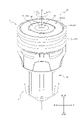
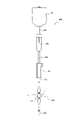
- FIG. 1 is a perspective view of an assembly according to one embodiment of the present disclosure
- FIG. Fig. 2 is an exploded perspective view of the assembly shown in Fig. 1 and showing a connector set according to one embodiment of the present disclosure
- Figure 2 is a top view of the assembly shown in Figure 1
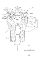
- 4 is a cross-sectional view of the assembly shown in FIG. 1 taken along line I-I in FIG. 3
- FIG. 4 is a cross-sectional view of the assembly shown in FIG. 1 taken along line II-II of FIG. 3
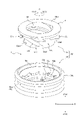
- FIG. 3 is an exploded perspective view of the conversion adapter shown in FIG. 2 and according to an embodiment of the present disclosure
- FIG. 3 is a diagram showing a rotation control mechanism of the conversion adapter shown in FIG. 2
- FIG. 3 is a diagram showing a rotation control mechanism of the conversion adapter shown in FIG. 2;
- FIG. 3 is a cross-sectional view showing a state in which a luer lock first male connector portion conforming to ISO80369 of another medical connector is connected to the medical connector shown in FIG. 2.
- FIG. 2 is a cross-sectional view showing a state in which a second male connector portion of another medical connector that does not conform to ISO 80369 is connected to the assembly shown in FIG. 1;
- FIG. FIG. 10 is a perspective view of the assembly and the medical connector shown in FIG. 9 in a connected state;
- 3 is a view showing a modification of the medical connector shown in FIG. 2 to which the conversion adapter shown in FIG. 2 can be attached;
- FIG. 10B is a diagram showing an example of an infusion line including an assembly in which the conversion adapter shown in FIG. 2 is attached to the medical connector shown in FIG. 10B.
- FIG. 10B is a diagram showing an example of an infusion line including an
- FIG. 1 is a perspective view showing an assembly 100 as one embodiment of an assembly according to the present disclosure.
- FIG. 2 is an exploded perspective view of assembly 100 shown in FIG.
- FIG. 2 is a diagram showing a connector set 200.
- the assembly 100 includes a conversion adapter 1 as one embodiment of the conversion adapter according to the present disclosure and a medical connector 2.
- the medical connector 2 includes a female connector portion 2a connectable to a luer lock type male connector portion 300a (see FIG. 8) conforming to ISO80369.
- the male connector portion 300a (see FIG.
- the conversion adapter 1 can be attached to the female connector portion 2a of the medical connector 2. As shown in FIG. Here, the conversion adapter 1 and the medical connector 2 may be distributed as an assembly 100 in which the conversion adapter 1 is attached to the female connector portion 2a of the medical connector 2, as shown in FIG.
- the conversion adapter 1 and the medical connector 2 are distributed together as a connector set 200 in separate states in which the conversion adapter 1 is not attached to the female connector portion 2a of the medical connector 2. good too. Furthermore, the conversion adapter 1 and the medical connector 2 may be distributed separately.
- the conversion adapter 1 is attached to a female connector section 2a connectable to a luer lock first male connector section 300a (see FIG. 8) conforming to ISO80369.
- the female connector portion 2a is configured to be connectable to a luer lock first male connector portion 300a (see FIG. 8) conforming to ISO80369 by screwing in a state in which the conversion adapter 1 is not attached.
- the female connector portion 2a is configured to be connectable to a male connector portion 400a (see FIG. 9) that does not conform to ISO80369 by a predetermined lock mechanism in a state where the conversion adapter 1 is attached.
- the male connector portion 400a see FIG.
- the conversion adapter 1 replaces the female connector portion 2a connectable with the first male connector portion 300a (see FIG. 8) of the luer lock type conforming to ISO80369 with the second male connector portion 400a (see FIG. 9) not conforming to ISO80369. ) and an adapter that converts into a connectable state by a predetermined locking mechanism.
- FIG. 3 is a top view of the assembly 100 when the assembly 100 is viewed from the top surface 12a side of the elastic valve body 12.
- FIG. 4 is a cross-sectional view of assembly 100 taken along line II of FIG.
- FIG. 5 is a cross-sectional view of assembly 100 taken along line II-II of FIG.
- the medical connector 2 includes a female connector portion 2a connectable to a luer lock first male connector portion 300a (see FIG. 8) conforming to ISO80369.
- the female connector portion 2a can be connected to the first male connector portion 300a (see FIG. 8) by screwing.
- the female connector portion 2a includes at least a tubular portion 2a1.
- a male threaded portion 40 that can be screwed with a female threaded portion 302a (see FIG. 8) of a luer lock first male connector portion 300a (see FIG. 8) conforming to ISO80369 is formed on the outer surface of the cylindrical portion 2a1.
- an insertion opening 14 into which a first male luer portion 301 see FIG.
- the medical connector 2 includes a housing 11 and an elastic valve body 12 to which the housing 11 is attached.
- the female connector portion 2a of the present embodiment is composed of a cap 16 which is a part of the housing 11 and an elastic valve body 12, which will be described later. Details of the tubular portion 2a1 of the female connector portion 2a of the present embodiment will be described later.
- the housing 11 defines a hollow portion 13.
- the elastic valve body 12 is positioned in the hollow portion 13 .
- the hollow portion 13 has an insertion opening 14 into which a first male connector portion 300a (see FIG. 8) and a second male connector portion 400a (see FIG. 9) can be inserted from the outside, and a channel communicating with the insertion opening 14. 15.
- the elastic valve body 12 closes the insertion opening 14 in the hollow portion 13 .
- the term "channel communicating with the insertion opening” means not only a channel directly communicating with the insertion opening but also a channel communicating with the insertion opening via another space.
- the channel 15 of this embodiment is a channel directly connected to the insertion opening 14 .
- the housing 11 defines a channel 15 and a cap 16 defining an insertion opening 14 into which the first male connector portion 300a (see FIG. 8) and the second male connector portion 400a (see FIG. 9) are inserted from the outside. and a holder 17 that supports the cap 16 .
- the cap 16 includes a top cap 18 and a bottom cap 19.
- the elastic valve body 12 is compressed and sandwiched by a top cap 18 and a bottom cap 19 to fix its position in the hollow portion 13 , more specifically in the insertion opening 14 .
- the holder 17 is a member that partitions the channel 15 and supports the top cap 18 and the bottom cap 19 .
- both the top cap 18 and the bottom cap 19 contact the holder 17 and are directly supported by the holder 17 .
- the bottom cap 19 may be held by the top cap 18, and only the top cap 18 may be in contact with the holder 17 and directly supported.
- the top cap 18 may be held by the bottom cap 19, and only the bottom cap 19 may be in contact with the holder 17 and directly supported.
- Materials for the holder 17, the top cap 18 and the bottom cap 19 of the housing 11 include polyolefins such as polyethylene, polypropylene, and ethylene-propylene copolymer; ethylene-vinyl acetate copolymer (EVA); polyvinyl chloride; Polyvinylidene chloride; Polystyrene; Polyamide; Polyimide; Polyamideimide; Polycarbonate; Poly-(4-methylpentene-1); Ionomer; Acrylic resin; Styrene copolymer (AS resin); butadiene-styrene copolymer; polyester such as polyethylene terephthalate (PET), polybutylene terephthalate (PBT), polycyclohexane terephthalate (PCT); polyether; polyether ketone (PEK); Ether ether ketone (PEEK); Polyetherimide; Polyacetal (POM); Polyphenylene oxide; Modified polyphenylene oxide; Polysulfone; Various resin materials such
- the elastic valve body 12 is elastically deformed and can be opened and closed when the first male connector portion 300a (see FIG. 8) and the second male connector portion 400a (see FIG. 9) are attached to and detached from the medical connector 2. has a slit 20 in the Further, the elastic valve body 12 is arranged so as to close the insertion opening 14 defined by the top cap 18 and the bottom cap 19 . Specifically, the elastic valve body 12 is clamped by a clamping portion composed of a top cap 18 and a bottom cap 19 to fix its position in the insertion opening 14 .
- the elastic valve body 12 is molded and formed to be elastically deformable.
- materials for the elastic valve body 12 include natural rubber, isoprene rubber, butadiene rubber, styrene-butadiene rubber, nitrile rubber, chloroprene rubber, butyl rubber, acrylic rubber, ethylene-propylene rubber, hydrin rubber, urethane rubber, silicone rubber, Various rubber materials such as fluororubber, styrene, polyolefin, polyvinyl chloride, polyurethane, polyester, polyamide, polybutadiene, transpolyisoprene, fluororubber, chlorinated polyethylene, etc.
- a plastic elastomer may be mentioned, and one or more of these may be mixed.
- the female connector portion 2a of the medical connector 2 of this embodiment is composed of the top cap 18, the bottom cap 19, and the elastic valve body 12 sandwiched between the top cap 18 and the bottom cap 19. ing.
- the top cap 18 includes a substantially cylindrical hollow cylinder portion 36 and a flange portion 37 .
- the flange portion 37 extends radially from the end in the insertion direction A1 of the first male connector portion 300a (see FIG. 8) and the second male connector portion 400a (see FIG. 9), which is one side of the hollow cylindrical portion 36 in the axial direction. It protrudes outward in direction B.
- the first male connector portion 300a (see FIG. 8) and the second male connector portion 400a (see FIG. 9), which are on the other side in the axial direction of the hollow cylindrical portion 36, are removed.
- a planar upper end face 38 extending in a direction orthogonal to the insertion direction A1 and the withdrawal direction A2 is provided at the end in the direction A2.
- the upper end surface 38 defines one end in the removal direction A2 of the insertion opening 14 into which the first male connector portion 300a (see FIG. 8) and the second male connector portion 400a (see FIG. 9) are inserted from the outside.
- a circular rim 39 is included.
- a male threaded portion 40 is formed on the outer peripheral surface of the hollow cylindrical portion 36 to be screwed with the female threaded portion 302a (see FIG. 8) of the luer lock type first male connector portion 300a (see FIG. 8) conforming to ISO80369.
- the flange portion 37 is formed integrally with the hollow cylindrical portion 36 , and the top cap 18 is held by the holder 17 by engaging the flange portion 37 with the holder 17 described later.
- a locking projection 41 is provided near the edge 39 of the inner wall of the hollow cylindrical portion 36 and protrudes in the insertion direction A1.
- the locking projection 41 enters the annular groove formed in the outer edge of the top surface 12 a of the elastic valve body 12 and compresses the elastic valve body 12 together with the locking projection 45 of the bottom cap 19 .
- the bottom cap 19 includes a substantially cylindrical hollow tube portion 43 and a flange portion 44, similar to the top cap 18.
- the flange portion 44 protrudes outward in the radial direction B from the end portion of the hollow cylindrical portion 43 in the insertion direction A1.
- the end portion of the hollow cylindrical portion 43 in the withdrawal direction A2 enters the annular groove formed in the outer edge portion of the bottom surface 12b of the elastic valve body 12 described above, and moves into the elastic valve body 12 together with the locking projection 41 of the top cap 18. are compressed and sandwiched.
- the bottom cap 19 is ultrasonically bonded to the inner surface of the hollow cylindrical portion 36 of the top cap 18 and/or the lower surface of the flange portion 37 (the lower surface in FIGS. 4 and 5). held.
- the lower surface of the flange portion 44 of the bottom cap 19 (lower surface in FIGS. 4 and 5) is supported by a holder 17 which will be described later.
- the holder 17 supports the top cap 18 and the bottom cap 19, and partitions the channel 15 therein.
- the holder 17 of the present embodiment supports the top cap 18 and the bottom cap 19 by directly contacting them, the configuration is not limited to that described above.
- members in direct contact with each other in the top cap 18 and the bottom cap 19 are preferably bonded by, for example, ultrasonic bonding.
- the holder 17 of the present embodiment includes a luer lock first male connector portion conforming to ISO80369.
- the holder 17 of the present embodiment includes a substantially cylindrical tubular portion 46 formed with a female threaded portion 46a that can be screwed with the male threaded portion 40 of the female connector portion 2a of another medical connector or the like; and a male luer portion 47 provided in a hollow portion defined by the tubular portion 46 .
- the shape of the holder 17 of the medical connector 2 is not limited to the configuration of this embodiment.
- the medical connector 2 may, for example, be configured to include a holder 517 as shown in FIG. 10B.
- the holder 517 includes a substantially cylindrical holder main body 517a that partitions a hollow portion inside, and tubular upstream port portions 517b and downstream port portions 517c that protrude from the outer peripheral surface of the holder main body 517a.
- a hollow portion inside the holder main body 517a serves as part of a flow path from the upstream port portion 517b to the downstream port portion 517c.
- the female connector portion 2a of the medical connector 2 is composed of the cap 16 and the elastic valve body 12.
- the tubular portion 2a1 of the female connector portion 2a is composed of the hollow tubular portion 36 of the top cap 18 and the hollow tubular portion 43 of the bottom cap 19.
- the male screw portion 40 formed on the outer surface of the hollow cylindrical portion 36 of the top cap 18 is a female screw portion 302a (see FIG. 8) of the luer lock type first male connector portion 300a (see FIG. 8) conforming to ISO80369. ) can be screwed together.
- a luer lock type first male connector portion 300a conforming to ISO 80369 is inserted.
- a single male luer 301 is insertable from the outside.
- the medical connector 2 of this embodiment includes the housing 11 and the elastic valve body 12, and the female connector portion 2a is constituted by part of the housing 11 and the elastic valve body 12.
- the medical connector 2 is configured to include a luer lock type male connector portion conforming to ISO80369, such as the first male connector portion 300a (see FIG. 8) shown in this embodiment, and a connectable female connector portion 2a, Well, the specific number of members and the shape of members are not particularly limited.
- the female connector portion 2a may be, for example, a luer lock type female connector portion conforming to ISO80369.
- FIG. 6 is an exploded perspective view of the conversion adapter 1 shown in FIG. 2.
- FIG. 7A and 7B are diagrams showing the rotation control mechanism of the conversion adapter 1.
- the conversion adapter 1 can be attached to a female connector portion 2a connectable to a luer lock first male connector portion 300a (see FIG. 8) conforming to ISO80369.
- the conversion adapter 1 includes a female threaded portion 50 that can be screwed with the male threaded portion 40 of the female connector portion 2a.
- the conversion adapter 1 is connected to the female connector portion 2a by threaded connection by screwing the female threaded portion 50 with the male threaded portion 40 .
- the conversion adapter 1 is provided with a female threaded portion 50 that can be screwed into the male threaded portion 40 of the female connector portion 2a that can be connected to the first male connector portion 300a (see FIG. 8) of the luer lock type that conforms to ISO80369.
- the adapter 1 can be easily connected to the female connector portion 2a.
- the conversion adapter 1 has a locking portion 51 capable of locking the second male connector portion 400a (see FIG. 9) that does not conform to ISO80369.
- the locking portion 51 of this embodiment is configured by an annular groove 51a as a concave portion that can be engaged with the locking claw 402 (see FIG. 9) of the second male connector portion 400a (see FIG. 9). It is
- the medical device such as the medical connector 2 having the female connector portion 2a can be used as a non-ISO 80369 standard regardless of the difference in the shape of the portion other than the female connector portion 2a.
- the 2 male connector portion 400a (see FIG. 9) can be locked using a predetermined locking mechanism using the locking portion 51 of the conversion adapter 1.
- the conversion adapter 1 of this embodiment includes a tubular adapter main body 52 .
- the female threaded portion 50 of the conversion adapter 1 of this embodiment is formed on the inner surface of the adapter main body 52.
- the locking portion 51 of the conversion adapter 1 of this embodiment is formed on the outer surface of the adapter main body 52.
- the conversion adapter 1 can have a simple configuration.
- the conversion adapter 1 of this embodiment is composed only of the cylindrical adapter main body 52, it is not limited to this configuration.
- the conversion adapter 1 may be configured to include another portion in addition to the cylindrical adapter main body 52 .
- the axial direction of the cylindrical adapter main body 52 will be referred to as “axial direction A of the adapter main body 52" or simply “axial direction A”.
- the axial direction A of the adapter body 52 is substantially parallel to the insertion direction A1 and withdrawal direction A2 of the female connector portion 2a when the adapter body 52 is connected to the female connector portion 2a. Therefore, hereinafter, one side of the axial direction A will be referred to as the insertion direction A1, and the other side of the axial direction A will be referred to as the withdrawal direction A2.
- the radial direction of the circle around the central axis O of the adapter main body 52 is referred to as "radial direction B of the adapter main body 52" or simply "radial direction B".
- the circumferential direction around the central axis O of the adapter body 52 is referred to as "circumferential direction C of the adapter body 52" or simply “circumferential direction C”.
- the central axis O, the radial direction B, and the circumferential direction C of the adapter main body 52 correspond to the central axis, radial direction, Match each circumferential direction. Therefore, in the drawings, for convenience of explanation, the central axis of the tubular portion 2a1 of the female connector portion 2a is also denoted by “O”, the radial direction of the tubular portion 2a1 is also denoted by “B”, and the circumferential direction of the tubular portion 2a1 is also denoted by "B”.
- the code is "C”.
- the adapter main body 52 of this embodiment includes an inner cylindrical body 53 and an outer cylindrical body 54 .
- the inner tubular body 53 includes an inner tubular portion 53a having an internal threaded portion 50 formed therein.
- the outer cylindrical body 54 includes an outer cylindrical portion 54a positioned radially outwardly of the inner cylindrical portion 53a in the B direction and having the locking portion 51 formed on the outer surface thereof.
- the inner cylindrical body 53 of the present embodiment includes an inner cylindrical portion 53a having the internal thread portion 50 formed on the inner surface as described above, and an end portion of the inner cylindrical portion 53a in the removal direction A2. It has an annular flange portion 53b projecting outward in the radial direction B, and a plurality of projecting portions 53c projecting from the flange portion 53b in the insertion direction A1.
- a support projection 53a1 for supporting the outer cylinder 54 from the insertion direction A1 side is projected from the end of the inner cylinder portion 53a in the insertion direction A1.
- a plurality of support protrusions 53a1 are provided at positions spaced apart in the circumferential direction C, but the number and positions thereof are not particularly limited.
- the support projections 53a1 of the present embodiment sandwich the outer cylindrical body 54 in the axial direction A together with the flange portion 53b, thereby restricting relative movement of the outer cylindrical body 54 with respect to the inner cylindrical body 53 in the axial direction A.
- the relative movement of the outer cylindrical body 54 with respect to the inner cylindrical body 53 in the insertion direction A1 is such that the later-described flange portion 54b of the outer cylindrical body 54 contacts the support projection 53a1 of the inner cylindrical portion 53a of the inner cylindrical body 53. controlled by contact.
- relative movement of the outer cylinder 54 with respect to the inner cylinder 53 in the removal direction A2 is restricted by the contact of the outer cylinder portion 54a of the outer cylinder 54 with the flange portion 53b of the inner cylinder 53 .
- the inner cylindrical body 53 and the outer cylindrical body 54 of this embodiment can be connected in the axial direction A so as not to be separated from each other. Therefore, unintentional separation of the inner tubular body 53 and the outer tubular body 54 is suppressed, and operability for a medical worker using the conversion adapter 1 can be improved.
- the plurality of protrusions 53c are arranged at predetermined intervals in the circumferential direction C.
- the plurality of projecting portions 53c of this embodiment are arranged at four equal intervals in the circumferential direction C. As shown in FIG.
- Each projecting portion 53c is located outside in the radial direction B with respect to the inner cylindrical portion 53a.
- each protrusion 53c is arranged so as to be spaced outward in the radial direction B from the outer surface of the inner cylindrical portion 53a.
- the protrusion 53c constitutes a part of the rotation control mechanism of this embodiment (see FIGS. 7A and 7B).
- the inner cylindrical body 53 of this embodiment has a plurality of protrusions 53c, but the number is not particularly limited.
- the number of protrusions 53c of the inner cylindrical body 53 may be only one, or may be plural other than four.
- each projecting portion 53c of the present embodiment is configured by a rod-like projection projecting from the flange portion 53b in a direction inclined with respect to the insertion direction A1.
- the rod-like protrusion as the protrusion 53c of the present embodiment protrudes in a direction inclined with respect to the axial direction A from the flange 53b. Therefore, as shown in FIGS. 7A and 7B, a lower side surface 53c1, which is the side surface of the protrusion 53c on the insertion direction A1 side, and an upper side surface 53c2, which is the side surface of the protrusion 53c on the removal direction A2 side, It is composed of an inclined surface that is inclined with respect to Further, as shown in FIGS. 7A and 7B, the tip surface 53c3 of the protrusion 53c is configured by a plane substantially parallel to the axial direction A. As shown in FIG.
- Each projecting portion 53c can swing by being elastically deformed in the axial direction A with the base end connected to the flange portion 53b as a fulcrum.
- the rotation control mechanism of the present embodiment is such that the projection 53c of the inner cylinder 53 swings in the axial direction A according to the engagement relationship with the projection 54b1 of the outer cylinder 54. , restricts or permits relative rotation of the inner cylinder 53 and the outer cylinder 54 (see FIGS. 7A and 7B).
- the outer cylindrical body 54 includes the outer cylindrical portion 54a having the locking portion 51 formed on the outer surface as described above, and the outer cylindrical portion 54a protruding inward in the radial direction B from the end portion of the outer cylindrical portion 54a in the insertion direction A1. and an annular flange portion 54b.
- the locking portion 51 formed on the outer surface of the outer cylindrical portion 54a is the annular groove 51a as a recess extending over the entire circumferential direction C, as described above.
- the locking portion 51 is not limited to the annular groove 51a of this embodiment.
- the locking portion 51 may be composed of a plurality of recesses spaced apart in the circumferential direction C, for example.
- the locking portion 51 can be appropriately designed according to the specific shape of the second male connector portion 400a (see FIG. 9), and is not limited to a concave portion. It is preferable to form a concave portion that can be engaged with the locking claw 402 (see FIG. 9) of the male connector portion 400a (see FIG. 9). By doing in this way, it is easy to implement
- a stepped surface 54a1 for supporting the flange portion 53b of the inner tubular body 53 from the insertion direction A1 side is formed on the inner surface of the outer tubular portion 54a.
- the outer cylindrical portion 54a of the present embodiment has different inner diameters on the insertion direction A1 side and on the withdrawal direction A2 side.
- the stepped surface 54a1 of the present embodiment is an annular plane facing the removal direction A2 and connecting the portions of the inner surface of the outer cylindrical portion 54a having different inner diameters.
- the flange portion 53b which constitutes the end portion of the inner cylindrical body 53 in the withdrawal direction A2, is accommodated in the outer cylindrical portion 54a, and the inner cylindrical body 53 and the outer cylindrical body 54 are separated from each other.
- the inner cylindrical body 53 and the outer cylindrical body 54 are arranged in a state in which the outer cylindrical body 54 covers the outer side of the inner cylindrical body 53 in the radial direction B so that the inner cylindrical body 53 cannot be held from the outside in the radial direction B. can be concatenated. Therefore, it is possible to suppress the rotation of the inner cylindrical body 53 so as to detach from the female connector section 2a in a state where the inner cylindrical body 53 is screwed to the female connector section 2a. Details of this will be described later.
- a plurality of convex portions 54b1 are provided on the surface of the flange portion 54b on the withdrawal direction A2 side.
- the plurality of protrusions 54b1 are arranged in the circumferential direction C at predetermined intervals. Twelve convex portions 54b1 of the present embodiment are arranged at regular intervals in the circumferential direction C. As shown in FIG. Although the details will be described later, the convex portion 54b1 constitutes a part of the rotation control mechanism of the present embodiment (see FIGS. 7A and 7B).
- the outer cylindrical body 54 of this embodiment has a plurality of projections 54b1, but the number is not particularly limited. The number of protrusions 54b1 of the outer cylindrical body 54 may be only one, or may be plural other than twelve.
- each convex portion 54b1 of the present embodiment is provided on one side in the circumferential direction C with a plane substantially parallel to the axial direction A.
- a motion control surface 55a is provided.
- each convex portion 54b1 of the present embodiment includes a rotation permitting surface 55b formed of a plane inclined with respect to the axial direction A on the other side in the circumferential direction C.
- the convex portion 54b1 of the present embodiment is a substantially triangular protrusion having both side surfaces of the rotation restricting surface 55a and the rotation allowing surface 55b, but the shape thereof is particularly limited as long as the rotation control described below is possible. not.
- a rotation control mechanism is provided between the inner cylindrical body 53 and the outer cylindrical body 54 of the present embodiment.
- the rotation control mechanism regulates the rotation of the outer cylinder 54 relative to the inner cylinder 53 toward one side in the circumferential direction C.
- the rotation control mechanism allows the outer cylinder 54 to rotate relative to the inner cylinder 53 in the other circumferential direction C.
- loosening of the screw connection between the female connector portion 2 a of the medical connector 2 and the inner cylinder 53 due to the rotation of the outer cylinder 54 can be suppressed.
- the female threaded portion 50 of the inner cylindrical body 53 rotates in the tightening direction C1, which is one side of the circumferential direction C, with respect to the male threaded portion 40 of the female connector portion 2a. By screwing together, it is screwed to the medical connector 2 . Conversely, when the conversion adapter 1 and the medical connector 2 are screwed together, the female threaded portion 50 of the inner cylindrical body 53 is positioned on the other side in the circumferential direction C with respect to the male threaded portion 40 of the female connector portion 2a. , the screw connection between the conversion adapter 1 and the medical connector 2 is loosened.
- the rotation control mechanism restricts the rotation of the outer cylinder 54 relative to the inner cylinder 53 in the tightening direction C1. That is, when the outer cylindrical body 54 tries to rotate in the tightening direction C1 relative to the inner cylindrical body 53, the outer cylindrical body 54 is restricted from rotating by the inner cylindrical body 53 and does not rotate relatively. . Therefore, when connecting the conversion adapter 1 to the female connector portion 2a of the medical connector 2, the outer cylindrical body 54 is rotated in the tightening direction C1. As a result, the inner cylindrical body 53 and the outer cylindrical body 54 are rotated together by the rotation control mechanism, and the female threaded portion 50 of the inner cylindrical body 53 is screwed to the male threaded portion 40 of the female connector portion 2a.
- the rotation control mechanism controls the rotation of the outer cylindrical body 54 relative to the inner cylindrical body 53 in the loosening direction C2. allow. That is, when the outer cylindrical body 54 tries to rotate in the loosening direction C2 relative to the inner cylindrical body 53, the outer cylindrical body 54 is not restricted by the inner cylindrical body 53 and rotates relatively. It is possible. Therefore, when the outer cylinder 54 is rotated in the loosening direction C2 while the conversion adapter 1 is connected to the female connector portion 2a of the medical connector 2, the outer cylinder 54 is rotated by the rotation control mechanism. It idles with respect to the inner cylindrical body 53 .
- the rotation control mechanism of this embodiment is a ratchet mechanism.
- the rotation control mechanism of the present embodiment is composed of the projection 53c of the inner cylinder 53 and the projection 54b1 of the outer cylinder 54. As shown in FIG.
- the tip surface 53c3 of the protrusion 53c of the inner cylinder 53 and the rotation restricting surface 55a of the protrusion 54b1 of the outer cylinder 54 are aligned in the circumferential direction. They are arranged so as to face each other at C.
- FIG. 7A shows a state in which the outer cylindrical body 54 is about to rotate relative to the inner cylindrical body 53 in the tightening direction C1 (leftward direction in FIGS. 7A and 7B).
- the rotation restricting surface 55a of the projection 54b1 is pushed by the protrusion of the inner cylindrical body 53. 53c, and presses the inner cylindrical body 53 in the tightening direction C1. That is, by attempting to rotate the outer cylinder 54 relative to the inner cylinder 53 in the tightening direction C1 (the left direction in FIG. 7A), the inner cylinder 53 and the outer cylinder 54 are rotated together. be able to.
- FIG. 7B shows a state in which the outer cylindrical body 54 is about to rotate relative to the inner cylindrical body 53 in the loosening direction C2 (rightward direction in FIGS. 7A and 7B).
- the rotation restricting surface 55a of the projection 54b1 moves toward the tip of the protrusion 53c of the inner cylinder 53. It does not hit the surface 53c3.
- the lower side surface 53c1 of the protrusion 53c slides on the rotation-permitting surface 55b of the protrusion 54b1, so that the base end connected to the flange 53b is used as a fulcrum to elastically deform and swing in the removal direction A2 ( See arrows in FIG. 7B).
- the projecting portion 53c can get over the projecting portion 54b1. That is, even if the outer cylinder 54 is rotated relative to the inner cylinder 53 in the loosening direction C2 (rightward direction in FIGS. 7A and 7B), the inner cylinder 53 does not rotate together with the outer cylinder 54. Therefore, the outer cylindrical body 54 idles with respect to the inner cylindrical body 53 .
- the rotation control mechanism is not limited to the configuration of this embodiment.
- the inner cylinder 53 has the protrusion 53c and the outer cylinder 54 has the protrusion 54b1.
- the shapes of the projecting portion 53c and the projecting portion 54b1 are not limited to the shapes of the present embodiment.
- the mechanism need not be a ratchet mechanism. However, by using the ratchet mechanism as in the present embodiment, the above rotation control can be easily realized with a simple configuration.
- the female threaded portion 50 of the adapter main body 52 of the present embodiment is such that the tip of the cylindrical portion 2a1 of the female connector portion 2a is aligned with one end of the adapter main body 52 in the axial direction A.
- the male screw portion 40 of the female connector portion 2a can be screwed together until it is flush with the inner edge of the end on the withdrawal direction A2 side, which is the inner edge of the female connector portion 2a. That is, the upper end surface 38 forming the tip of the cylindrical portion 2a1 of the female connector portion 2a of the present embodiment is in a state where the conversion adapter 1 is connected to the female connector portion 2a (see FIGS. 1, 4, and 5).
- the tip of the tubular portion 2a1 of the female connector portion 2a is exposed from the conversion adapter 1, so that the tip of the tubular portion 2a1 can be easily cleaned, and the wiping performance of the tubular portion 2a1 can be improved. can be enhanced.
- the female threaded portion 50 of the adapter body 52 may be configured to be screwed with the male threaded portion 40 of the female connector portion 2a until the cylindrical portion 2a1 of the female connector portion 2a passes through the adapter body 52 in the axial direction A. By doing so, it is possible to improve the wiping performance of the cylindrical portion 2a1 as described above.
- FIG. 8 is a cross-sectional view showing a state in which the female connector portion 2a of the medical connector 2 is connected to the luer lock first male connector portion 300a of another medical connector 300 conforming to ISO80369.
- the first male connector portion 300a of the medical connector 300 includes a first male luer portion 301 and a cylindrical portion 302 surrounding the first male luer portion 301 radially outwardly.
- a female threaded portion 302a is formed on the inner surface of the tubular portion 302 .
- the conversion adapter 1 is not connected to the female connector portion 2a of the medical connector 2.
- the first male luer portion 301 of the first male connector portion 300a is inserted from the outside into the insertion opening 14 of the tubular portion 2a1 of the female connector portion 2a.
- the male screw portion 40 of the tubular portion 2a1 of the female connector portion 2a is screwed into the female screw portion 302a of the first male connector portion 300a, thereby connecting the female connector portion 2a and the first male connector portion 300a.
- FIG. 9 shows a state in which the conversion adapter 1 is connected to the female connector portion 2a of the medical connector 2, and the second male connector portion 400a of another medical connector 400, which does not conform to ISO 80369, is connected. It is a sectional view showing.
- the second male connector portion 400a of the medical connector 400 includes a second male luer portion 401 and a locking claw 402 located radially outside the second male luer portion 401. As shown in FIG. 9, the second male connector portion 400a of the medical connector 400 includes a second male luer portion 401 and a locking claw 402 located radially outside the second male luer portion 401. As shown in FIG. 9, the second male connector portion 400a of the medical connector 400 includes a second male luer portion 401 and a locking claw 402 located radially outside the second male luer portion 401.
- the second male luer portion 401 of the second male connector portion 400a is inserted from the outside into the insertion opening 14 of the tubular portion 2a1 of the female connector portion 2a.
- the tip projection 402a of the locking claw 402 of the second male connector portion 400a into the annular groove 51a of the locking portion 51 of the conversion adapter 1 connected to the female connector portion 2a.
- the female connector portion 2a to which the conversion adapter 1 is connected and the second male connector portion 400a are connected.
- the use of the conversion adapter 1 facilitates the attachment operation of the male connector section to the female connector section 2a. More specifically, as shown in FIG. 8, when connecting the first male connector portion 300a to the female connector portion 2a, the first male connector portion 300a is placed relatively in the circumferential direction of the tubular portion 2a1 of the female connector portion 2a. It is screwed by rotating it. On the other hand, as shown in FIG. 9, when connecting the second male connector portion 400a to the female connector portion 2a, the second male connector portion 400a is brought close to the insertion direction A1 of the female connector portion 2a, Insert the two-male luer part 401 into the insertion opening 14 .
- the locking claw 402 of the second male connector portion 400a engages with the annular groove 51a as the locking portion 51 of the conversion adapter 1,
- the connection between the connector portion 2a and the second male connector portion 400a is completed. That is, only by moving the second male connector portion 400a relative to the female connector portion 2a in the insertion direction A1, the female connector portion 2a and the second male connector portion 400a can be engaged with the locking claws 402 and the annular groove 51a. It can be connected in a predetermined locked state by
- the second male connector portion that can be connected in the locked state is not limited to the configuration shown in FIG. That is, the second male connector portion may have a different shape that does not comply with ISO80369.
- 10A and 10B are diagrams showing two types of medical connectors 2 having a female connector portion 2a with different holder shapes. 10A and 10B show a state in which the medical connector 400 shown in FIG. 9 is connected to two types of medical connectors 2.
- FIG. The medical connector 2 shown in FIG. 10A is similar in construction to those shown in FIGS.
- the medical connector 2 shown in FIG. 10B includes a holder 517 having a substantially cylindrical holder body 517a, an upstream port portion 517b and a downstream port portion 517c.
- the second male connector portion 400a that does not conform to ISO 80369 can be locked using a predetermined locking mechanism using the locking portion 51 of the conversion adapter 1. .
- An infusion line 600 includes an infusion tube 603 and a clamp 604 between an infusion bag 601 containing a liquid such as a drug solution and an indwelling needle 602 inserted into a patient's vein or the like. It is configured.
- the medical connector 2 is provided on the infusion line 600 , and enables a luer lock first male connector portion 300 a (see FIG. 8 ) conforming to ISO80369 to be connected to the infusion line 600 .
- FIG. 11 shows a state (assembly state) in which the conversion adapter 1 is attached to the female connector portion 2a (see FIG. 2, etc.) of the medical connector 2.
- FIG. 11 shows the infusion line 600 including the medical connector 2 shown in FIG. 10B, the infusion line 600 may include the medical connector 2 shown in FIG. 2 and the like.
- the conversion adapter, connector set, and assembly according to the present disclosure are not limited to the specific configurations shown in the above-described embodiments, and various modifications, changes, and combinations are possible without departing from the scope of the claims.
- the connector set 200 shown in FIG. 2 may include other medical instruments such as a medical tube 605 shown in FIG. 11 in addition to the conversion adapter 1 and the medical connector 2 . That is, the connector set 200 may be an infusion set including the conversion adapter 1 and the medical connector 2 .
- the assembly 100 has a configuration in which the conversion adapter 1 is attached to the medical connector 2, but the assembly 100 is not limited to this configuration.
- the assembly 100 may be configured to include the conversion adapter 1 and the female connector portion 2a to which the conversion adapter 1 is attached, and the medical device including the female connector portion 2a is limited to the medical connector 2. do not have.
- the present disclosure relates to conversion adapters, connector sets and assemblies.
- Conversion adapter 2 Medical connector 2a: Female connector part 2a1: Cylindrical part 11: Housing 12: Elastic valve body 12a: Top surface 12b of elastic valve body: Bottom surface of elastic valve body 13: Hollow part 14: Insertion opening 15 : Flow path 16: Cap 17: Holder 18: Top cap 19: Bottom cap 20: Slit 36: Top cap hollow cylindrical portion 37: Top cap flange 38: Top cap upper end surface 39: Top surface Cap top edge 40: Top cap male thread 41: Top cap locking projection 43: Bottom cap hollow cylinder 44: Bottom cap flange 45: Bottom cap locking projection 46: Holder Cylindrical portion 46a: female threaded portion 47 of holder: male luer portion 50: female threaded portion 51: locking portion 51a: annular groove (recess) 52: Adapter main body 53: Inner cylindrical body 53a: Inner cylindrical portion 53a1: Support projection 53b: Flange portion 53b1: Upper surface of flange portion 53c: Protruding portion (part of rotation control mechanism) 53c1: lower
Abstract
A conversion adapter according to the present disclosure is provided with: a female threaded part that can be attached to a female connector part in which a male threaded part capable of connecting a luer lock-type first male connector part conforming to ISO80369 is formed, and that can be screwed together with the male threaded part of the female connector part; and a lock part capable of engaging with a second male connector that does not conform to ISO80369.
Description
本開示は変換アダプタ、コネクタセット及び組立体に関する。
The present disclosure relates to conversion adapters, connector sets and assemblies.
従来から、国際標準化機構の国際規格であるISO80369に準拠する医療用のオスコネクタ部が知られている。その一方で、例えば特定の用途で使用する医療用コネクタなどにおいて、ISO80369に準拠しないオスコネクタ部が用いられる場合がある。
Medical male connector parts that conform to ISO80369, the international standard of the International Organization for Standardization, have been known for some time. On the other hand, there are cases where a male connector portion that does not conform to ISO80369 is used, for example, in a medical connector used for a specific application.
特許文献1には、混注ポートに着脱自在に取り付けられるアダプタが記載されている。特許文献1に記載のアダプタを混注ポートに取り付けることで、ロック式ルアー部及びスリップ式ルアー部の両方を混注ポートに接続することができる。
Patent Document 1 describes an adapter that is detachably attached to a mixed injection port. By attaching the adapter described in Patent Document 1 to the mixed injection port, both the lock luer portion and the slip luer portion can be connected to the mixed injection port.
医療現場の医療従事者の作業効率の観点では、ISO80369に準拠するルアーロック式のオスコネクタ部と接続可能なメスコネクタ部を、ISO80369に準拠しないオスコネクタ部と所定のロック機構を用いたロック状態で接続可能なメスコネクタ部へと、簡単に変換できることが望ましい。
From the viewpoint of the work efficiency of medical personnel in the medical field, the female connector part that can be connected to the luer lock type male connector part that conforms to ISO80369 is replaced with a male connector part that does not conform to ISO80369 and a locked state using a predetermined locking mechanism. It is desirable to be able to easily convert to a female connector part that can be connected with
本開示は、ISO80369に準拠するルアーロック式のオスコネクタ部と接続可能なメスコネクタ部を、ISO80369に準拠しないオスコネクタ部と所定のロック機構を用いたロック状態で接続可能なメスコネクタ部へと、簡単に変換可能な変換アダプタ、変換アダプタを含むコネクタセット、及び、変換アダプタを備える組立体、を提供することを目的とする。
The present disclosure converts a female connector section connectable to a luer lock type male connector section conforming to ISO80369 into a female connector section connectable to a male connector section not conforming to ISO80369 in a locked state using a predetermined locking mechanism. , an easily convertible conversion adapter, a connector set including the conversion adapter, and an assembly provided with the conversion adapter.
本開示の第1の態様としての変換アダプタは、ISO80369に準拠するルアーロック式の第1オスコネクタ部を接続可能な雄ねじ部が形成されているメスコネクタ部に取り付け可能であり、前記メスコネクタ部の前記雄ねじ部と螺合可能な雌ねじ部と、ISO80369に準拠しない第2オスコネクタ部を係止可能な係止部と、を備える。
A conversion adapter according to a first aspect of the present disclosure is attachable to a female connector portion having a male screw portion that can be connected to a luer lock type first male connector portion conforming to ISO80369, and the female connector portion and a locking portion capable of locking the second male connector portion that does not conform to ISO80369.
本開示の1つの実施形態としての変換アダプタは、筒状のアダプタ本体を備え、前記雌ねじ部は、前記アダプタ本体の内面に形成されており、前記係止部は、前記アダプタ本体の外面に形成されている。
A conversion adapter as one embodiment of the present disclosure includes a cylindrical adapter body, the internal thread portion is formed on the inner surface of the adapter body, and the locking portion is formed on the outer surface of the adapter body. It is
本開示の1つの実施形態として、前記アダプタ本体は、前記雌ねじ部が内面に形成されている内筒部を備える内筒体と、前記内筒部に対して径方向外側に位置し外面に前記係止部が形成されている外筒部を備える外筒体と、を備える。
As one embodiment of the present disclosure, the adapter main body includes an inner cylindrical body including an inner cylindrical portion having the internal thread formed on the inner surface thereof, and an outer cylindrical body including an outer cylindrical portion in which a locking portion is formed.
本開示の1つの実施形態としての変換アダプタには、前記内筒体及び前記外筒体の相互間に、前記外筒体が前記内筒体に対して前記アダプタ本体の周方向の一方側へ相対的に回動することを規制し、前記外筒体が前記内筒体に対して前記周方向の他方側へ相対的な回動することを許容する、回動制御機構が設けられている。
In a conversion adapter as one embodiment of the present disclosure, between the inner cylinder and the outer cylinder, the outer cylinder extends toward one side of the adapter body in the circumferential direction with respect to the inner cylinder. A rotation control mechanism is provided that restricts relative rotation and allows the outer cylinder to rotate relative to the inner cylinder in the other circumferential direction. .
本開示の1つの実施形態として、前記アダプタ本体の前記雌ねじ部は、前記メスコネクタ部の前記雄ねじ部が形成されている筒部が前記アダプタ本体を軸方向に貫通するまで、又は、前記筒部の先端が、前記アダプタ本体の前記軸方向の一端の内縁と面一になるまで、前記メスコネクタ部の前記雄ねじ部と螺合可能に構成されている。
As one embodiment of the present disclosure, the female threaded portion of the adapter body extends until the cylindrical portion of the female connector portion on which the male threaded portion is formed penetrates the adapter body in the axial direction, or the cylindrical portion is configured to be screwable with the male threaded portion of the female connector portion until the tip of the female connector portion is flush with the inner edge of the one axial end of the adapter body.
本開示の1つの実施形態として、前記メスコネクタ部は、前記第1オスコネクタ部の第1オスルアー部、及び、前記第2オスコネクタ部の第2オスルアー部、を外部から挿入可能な挿入開口を区画する前記筒部と、前記挿入開口を閉塞する弁体と、を備える。
As one embodiment of the present disclosure, the female connector section has an insertion opening into which a first male luer section of the first male connector section and a second male luer section of the second male connector section can be inserted from the outside. It includes the cylindrical portion that partitions and a valve body that closes the insertion opening.
本開示の1つの実施形態として、前記係止部は、前記第2オスコネクタ部の係止爪と係合可能な凹部により構成されている。
As one embodiment of the present disclosure, the locking portion is configured by a concave portion that can be engaged with a locking pawl of the second male connector portion.
本開示の第2の態様としてのコネクタセットは、上記変換アダプタと、前記変換アダプタを取り付け可能な前記メスコネクタ部を備える医療用コネクタと、を含む。
A connector set as a second aspect of the present disclosure includes the conversion adapter and a medical connector including the female connector portion to which the conversion adapter can be attached.
本開示の第3の態様としての組立体は、上記変換アダプタと、前記変換アダプタが取り付けられている前記メスコネクタ部と、を備える。
An assembly as a third aspect of the present disclosure includes the conversion adapter and the female connector section to which the conversion adapter is attached.
本開示によれば、ISO80369に準拠するルアーロック式のオスコネクタ部と接続可能なメスコネクタ部を、ISO80369に準拠しないオスコネクタ部と所定のロック機構を用いたロック状態で接続可能なメスコネクタ部へと、簡単に変換可能な変換アダプタ、変換アダプタを含むコネクタセット、及び、変換アダプタを備える組立体、を提供することができる。
According to the present disclosure, a female connector section connectable to a luer lock type male connector section conforming to ISO80369 can be connected to a male connector section not conforming to ISO80369 in a locked state using a predetermined locking mechanism. , a connector set including the conversion adapter, and an assembly including the conversion adapter can be provided.
以下、本開示に係る変換アダプタ、コネクタセット及び組立体の実施形態について図面を参照して例示説明する。各図において共通する構成には同一の符号を付している。
Hereinafter, embodiments of a conversion adapter, a connector set, and an assembly according to the present disclosure will be described with reference to the drawings. The same reference numerals are given to the configurations that are common in each figure.
図1は、本開示に係る組立体の一実施形態としての組立体100を示す斜視図である。図2は、図1に示す組立体100の分解斜視図である。換言すれば、図2は、コネクタセット200を示す図である。図1、図2に示すように、組立体100は、本開示に係る変換アダプタの一実施形態としての変換アダプタ1と、医療用コネクタ2と、を備える。図2に示すように、医療用コネクタ2は、ISO80369に準拠するルアーロック式のオスコネクタ部300a(図8参照)と接続可能なメスコネクタ部2aを備える。以下、後述する別のオスコネクタ部400a(図9参照)と区別する目的で、説明の便宜上、オスコネクタ部300a(図8参照)を「第1オスコネクタ部300a」と記載する。また、上述の「ISO80369に準拠するルアーロック式のオスコネクタ部」とは、ISO80369-2~ISO80369-7に準拠するルアーロック式のオスコネクタ部を意味する。図1に示すように、変換アダプタ1は、医療用コネクタ2のメスコネクタ部2aに取り付け可能である。ここで、変換アダプタ1及び医療用コネクタ2は、図1に示すように、変換アダプタ1が医療用コネクタ2のメスコネクタ部2aに取り付けられた組立体100の状態で流通してもよい。また、変換アダプタ1及び医療用コネクタ2は、図2に示すように、変換アダプタ1が医療用コネクタ2のメスコネクタ部2aに取り付けられていない別々の状態で一緒にコネクタセット200として流通してもよい。更に、変換アダプタ1及び医療用コネクタ2がそれぞれ別々に流通してもよい。
FIG. 1 is a perspective view showing an assembly 100 as one embodiment of an assembly according to the present disclosure. FIG. 2 is an exploded perspective view of assembly 100 shown in FIG. In other words, FIG. 2 is a diagram showing a connector set 200. As shown in FIG. As shown in FIGS. 1 and 2, the assembly 100 includes a conversion adapter 1 as one embodiment of the conversion adapter according to the present disclosure and a medical connector 2. As shown in FIG. As shown in FIG. 2, the medical connector 2 includes a female connector portion 2a connectable to a luer lock type male connector portion 300a (see FIG. 8) conforming to ISO80369. Hereinafter, the male connector portion 300a (see FIG. 8) will be referred to as a "first male connector portion 300a" for convenience of explanation in order to distinguish it from another male connector portion 400a (see FIG. 9) which will be described later. Further, the above-mentioned “luer lock type male connector portion conforming to ISO80369” means a luer lock type male connector portion conforming to ISO80369-2 to ISO80369-7. As shown in FIG. 1, the conversion adapter 1 can be attached to the female connector portion 2a of the medical connector 2. As shown in FIG. Here, the conversion adapter 1 and the medical connector 2 may be distributed as an assembly 100 in which the conversion adapter 1 is attached to the female connector portion 2a of the medical connector 2, as shown in FIG. 2, the conversion adapter 1 and the medical connector 2 are distributed together as a connector set 200 in separate states in which the conversion adapter 1 is not attached to the female connector portion 2a of the medical connector 2. good too. Furthermore, the conversion adapter 1 and the medical connector 2 may be distributed separately.
図1、図2に示すように、変換アダプタ1は、ISO80369に準拠するルアーロック式の第1オスコネクタ部300a(図8参照)と接続可能なメスコネクタ部2aに取り付けられる。メスコネクタ部2aは、変換アダプタ1が取り付けられていない状態で、ISO80369に準拠するルアーロック式の第1オスコネクタ部300a(図8参照)と螺合により接続可能に構成されている。これに対して、メスコネクタ部2aは、変換アダプタ1が取り付けられている状態で、ISO80369に準拠しないオスコネクタ部400a(図9参照)と、所定のロック機構により接続可能に構成されている。以下、上述の別の第1オスコネクタ部300a(図8参照)と区別する目的で、説明の便宜上、オスコネクタ部400a(図9参照)を「第2オスコネクタ部400a」と記載する。すなわち、変換アダプタ1は、ISO80369に準拠するルアーロック式の第1オスコネクタ部300a(図8参照)と接続可能なメスコネクタ部2aを、ISO80369に準拠しない第2オスコネクタ部400a(図9参照)と所定のロック機構により接続可能な状態へと変換するアダプタである。
As shown in FIGS. 1 and 2, the conversion adapter 1 is attached to a female connector section 2a connectable to a luer lock first male connector section 300a (see FIG. 8) conforming to ISO80369. The female connector portion 2a is configured to be connectable to a luer lock first male connector portion 300a (see FIG. 8) conforming to ISO80369 by screwing in a state in which the conversion adapter 1 is not attached. On the other hand, the female connector portion 2a is configured to be connectable to a male connector portion 400a (see FIG. 9) that does not conform to ISO80369 by a predetermined lock mechanism in a state where the conversion adapter 1 is attached. Hereinafter, the male connector portion 400a (see FIG. 9) will be referred to as a “second male connector portion 400a” for convenience of explanation in order to distinguish it from the above-described separate first male connector portion 300a (see FIG. 8). That is, the conversion adapter 1 replaces the female connector portion 2a connectable with the first male connector portion 300a (see FIG. 8) of the luer lock type conforming to ISO80369 with the second male connector portion 400a (see FIG. 9) not conforming to ISO80369. ) and an adapter that converts into a connectable state by a predetermined locking mechanism.
[医療用コネクタ2]
まず、図1~図5を参照して、変換アダプタ1が取り付けられるメスコネクタ部2aを含む医療用コネクタ2の概要について説明する。図3は、組立体100を弾性弁体12の天面12a側から見た、組立体100の上面図である。図4は、図3のI-I線の位置での組立体100の断面図である。図5は、図3のII-II線の位置での組立体100の断面図である。 [Medical connector 2]
First, with reference to FIGS. 1 to 5, an overview of themedical connector 2 including the female connector portion 2a to which the conversion adapter 1 is attached will be described. FIG. 3 is a top view of the assembly 100 when the assembly 100 is viewed from the top surface 12a side of the elastic valve body 12. FIG. FIG. 4 is a cross-sectional view of assembly 100 taken along line II of FIG. FIG. 5 is a cross-sectional view of assembly 100 taken along line II-II of FIG.
まず、図1~図5を参照して、変換アダプタ1が取り付けられるメスコネクタ部2aを含む医療用コネクタ2の概要について説明する。図3は、組立体100を弾性弁体12の天面12a側から見た、組立体100の上面図である。図4は、図3のI-I線の位置での組立体100の断面図である。図5は、図3のII-II線の位置での組立体100の断面図である。 [Medical connector 2]
First, with reference to FIGS. 1 to 5, an overview of the
図1~図5に示すように、医療用コネクタ2は、ISO80369に準拠するルアーロック式の第1オスコネクタ部300a(図8参照)と接続可能なメスコネクタ部2aを備える。具体的に、メスコネクタ部2aは、第1オスコネクタ部300a(図8参照)と螺合により接続可能である。メスコネクタ部2aは、少なくとも筒部2a1を備える。筒部2a1の外面には、ISO80369に準拠するルアーロック式の第1オスコネクタ部300a(図8参照)の雌ねじ部302a(図8参照)と螺合可能な雄ねじ部40が形成されている。また、筒部2a1の内部には、ISO80369に準拠するルアーロック式の第1オスコネクタ部300a(図8参照)の第1オスルアー部301(図8参照)が挿入される挿入開口14が区画されている。また、変換アダプタ1がメスコネクタ部2aに取り付けられている状態では、筒部2a1が区画する挿入開口14に、ISO80369に準拠しない第2オスコネクタ部400a(図9参照)の第2オスルアー部401(図9参照)が挿入可能である。
As shown in FIGS. 1 to 5, the medical connector 2 includes a female connector portion 2a connectable to a luer lock first male connector portion 300a (see FIG. 8) conforming to ISO80369. Specifically, the female connector portion 2a can be connected to the first male connector portion 300a (see FIG. 8) by screwing. The female connector portion 2a includes at least a tubular portion 2a1. A male threaded portion 40 that can be screwed with a female threaded portion 302a (see FIG. 8) of a luer lock first male connector portion 300a (see FIG. 8) conforming to ISO80369 is formed on the outer surface of the cylindrical portion 2a1. In addition, an insertion opening 14 into which a first male luer portion 301 (see FIG. 8) of a luer lock type first male connector portion 300a (see FIG. 8) conforming to ISO80369 is inserted is defined in the cylindrical portion 2a1. ing. Further, when the conversion adapter 1 is attached to the female connector portion 2a, the second male luer portion 401 of the second male connector portion 400a (see FIG. 9) that does not conform to ISO80369 is inserted into the insertion opening 14 defined by the cylindrical portion 2a1. (see FIG. 9) can be inserted.
より具体的には、図1~図5に示すように、医療用コネクタ2は、ハウジング11と、このハウジング11の取り付けられる弾性弁体12と、を備える。本実施形態のメスコネクタ部2aは、ハウジング11の一部である後述のキャップ16と、弾性弁体12と、により構成されている。本実施形態のメスコネクタ部2aの筒部2a1の詳細は後述する。
More specifically, as shown in FIGS. 1 to 5, the medical connector 2 includes a housing 11 and an elastic valve body 12 to which the housing 11 is attached. The female connector portion 2a of the present embodiment is composed of a cap 16 which is a part of the housing 11 and an elastic valve body 12, which will be described later. Details of the tubular portion 2a1 of the female connector portion 2a of the present embodiment will be described later.
図4、図5に示すように、ハウジング11は、中空部13を区画している。そして、弾性弁体12は、中空部13に位置している。中空部13は、後述する第1オスコネクタ部300a(図8参照)及び第2オスコネクタ部400a(図9参照)が外方から挿入可能な挿入開口14及びこの挿入開口14と連通する流路15を有する。弾性弁体12は、中空部13のうち挿入開口14を閉塞している。「挿入開口と連通する流路」とは、挿入開口と直接繋がる流路のみならず、挿入開口と別の空間を介して繋がる流路をも含む意味である。本実施形態の流路15は、挿入開口14と直接繋がる流路である。
As shown in FIGS. 4 and 5, the housing 11 defines a hollow portion 13. As shown in FIGS. The elastic valve body 12 is positioned in the hollow portion 13 . The hollow portion 13 has an insertion opening 14 into which a first male connector portion 300a (see FIG. 8) and a second male connector portion 400a (see FIG. 9) can be inserted from the outside, and a channel communicating with the insertion opening 14. 15. The elastic valve body 12 closes the insertion opening 14 in the hollow portion 13 . The term "channel communicating with the insertion opening" means not only a channel directly communicating with the insertion opening but also a channel communicating with the insertion opening via another space. The channel 15 of this embodiment is a channel directly connected to the insertion opening 14 .
ハウジング11は、第1オスコネクタ部300a(図8参照)及び第2オスコネクタ部400a(図9参照)が外方から挿入される挿入開口14を区画するキャップ16と、流路15を区画すると共に、キャップ16を支持するホルダ17とを備える。
The housing 11 defines a channel 15 and a cap 16 defining an insertion opening 14 into which the first male connector portion 300a (see FIG. 8) and the second male connector portion 400a (see FIG. 9) are inserted from the outside. and a holder 17 that supports the cap 16 .
キャップ16は、天面キャップ18と、底面キャップ19と、を備える。弾性弁体12は、天面キャップ18及び底面キャップ19により圧縮、挟持されて中空部13内、より具体的には挿入開口14内での位置が固定されている。
The cap 16 includes a top cap 18 and a bottom cap 19. The elastic valve body 12 is compressed and sandwiched by a top cap 18 and a bottom cap 19 to fix its position in the hollow portion 13 , more specifically in the insertion opening 14 .
ホルダ17は、流路15を区画すると共に、天面キャップ18及び底面キャップ19を支持する部材である。本実施形態では天面キャップ18及び底面キャップ19の両方がホルダ17に接触してホルダ17に直接的に支持される。但し、この構成に限られない。底面キャップ19が天面キャップ18に保持され、天面キャップ18のみがホルダ17に接触し、直接的に支持される構成であってもよい。また逆に、天面キャップ18が底面キャップ19に保持され、底面キャップ19のみがホルダ17に接触し、直接的に支持される構成であってもよい。
The holder 17 is a member that partitions the channel 15 and supports the top cap 18 and the bottom cap 19 . In this embodiment, both the top cap 18 and the bottom cap 19 contact the holder 17 and are directly supported by the holder 17 . However, it is not limited to this configuration. The bottom cap 19 may be held by the top cap 18, and only the top cap 18 may be in contact with the holder 17 and directly supported. Conversely, the top cap 18 may be held by the bottom cap 19, and only the bottom cap 19 may be in contact with the holder 17 and directly supported.
ハウジング11のホルダ17、天面キャップ18及び底面キャップ19の材料としては、例えば、ポリエチレン、ポリプロピレン、エチレン-プロピレン共重合体等のポリオレフィン;エチレン-酢酸ビニル共重合体(EVA);ポリ塩化ビニル;ポリ塩化ビニリデン;ポリスチレン;ポリアミド;ポリイミド;ポリアミドイミド;ポリカーボネート;ポリ-(4-メチルペンテン-1);アイオノマー;アクリル樹脂;ポリメチルメタクリレート;アクリロニトリル-ブタジエン-スチレン共重合体(ABS樹脂);アクリロニトリル-スチレン共重合体(AS樹脂);ブタジエン-スチレン共重合体;ポリエチレンテレフタレート(PET)、ポリブチレンテレフタレート(PBT)、ポリシクロヘキサンテレフタレート(PCT)等のポリエステル;ポリエーテル;ポリエーテルケトン(PEK);ポリエーテルエーテルケトン(PEEK);ポリエーテルイミド;ポリアセタール(POM);ポリフェニレンオキシド;変性ポリフェニレンオキシド;ポリサルフォン;ポリエーテルサルフォン;ポリフェニレンサルファイド;ポリアリレート;芳香族ポリエステル(液晶ポリマー);ポリテトラフルオロエチレン、ポリフッ化ビニリデン、その他フッ素系樹脂;などの各種樹脂材料が挙げられる。また、これらのうちの1種以上を含むブレンド体やポリマーアロイなどでもよい。その他に、各種ガラス材、セラミックス材料、金属材料であってもよい。
Materials for the holder 17, the top cap 18 and the bottom cap 19 of the housing 11 include polyolefins such as polyethylene, polypropylene, and ethylene-propylene copolymer; ethylene-vinyl acetate copolymer (EVA); polyvinyl chloride; Polyvinylidene chloride; Polystyrene; Polyamide; Polyimide; Polyamideimide; Polycarbonate; Poly-(4-methylpentene-1); Ionomer; Acrylic resin; Styrene copolymer (AS resin); butadiene-styrene copolymer; polyester such as polyethylene terephthalate (PET), polybutylene terephthalate (PBT), polycyclohexane terephthalate (PCT); polyether; polyether ketone (PEK); Ether ether ketone (PEEK); Polyetherimide; Polyacetal (POM); Polyphenylene oxide; Modified polyphenylene oxide; Polysulfone; Various resin materials such as vinylidene chloride and other fluorine-based resins are included. Blends or polymer alloys containing one or more of these may also be used. In addition, various glass materials, ceramic materials, and metal materials may be used.
弾性弁体12は、第1オスコネクタ部300a(図8参照)及び第2オスコネクタ部400a(図9参照)が医療用コネクタ2に着脱される際に弾性変形して開閉することができるようにスリット20を有する。また、弾性弁体12は、天面キャップ18及び底面キャップ19により区画された挿入開口14を閉塞するように配置されている。具体的に、弾性弁体12は、天面キャップ18と底面キャップ19とで構成される挟持部により挟持されて、挿入開口14内での位置が固定される。
The elastic valve body 12 is elastically deformed and can be opened and closed when the first male connector portion 300a (see FIG. 8) and the second male connector portion 400a (see FIG. 9) are attached to and detached from the medical connector 2. has a slit 20 in the Further, the elastic valve body 12 is arranged so as to close the insertion opening 14 defined by the top cap 18 and the bottom cap 19 . Specifically, the elastic valve body 12 is clamped by a clamping portion composed of a top cap 18 and a bottom cap 19 to fix its position in the insertion opening 14 .
弾性弁体12は、金型成形され、弾性変形可能に形成される。この弾性弁体12の材料としては、例えば、天然ゴム、イソプレンゴム、ブタジエンゴム、スチレン-ブタジエンゴム、ニトリルゴム、クロロプレンゴム、ブチルゴム、アクリルゴム、エチレン-プロピレンゴム、ヒドリンゴム、ウレタンゴム、シリコーンゴム、フッ素ゴムのような各種ゴム材料や、スチレン系、ポリオレフィン系、ポリ塩化ビニル系、ポリウレタン系、ポリエステル系、ポリアミド系、ポリブタジエン系、トランスポリイソプレン系、フッ素ゴム系、塩素化ポリエチレン系等の各種熱可塑性エラストマが挙げられ、これらのうちの1種または2種以上を混合した構成であってもよい。
The elastic valve body 12 is molded and formed to be elastically deformable. Examples of materials for the elastic valve body 12 include natural rubber, isoprene rubber, butadiene rubber, styrene-butadiene rubber, nitrile rubber, chloroprene rubber, butyl rubber, acrylic rubber, ethylene-propylene rubber, hydrin rubber, urethane rubber, silicone rubber, Various rubber materials such as fluororubber, styrene, polyolefin, polyvinyl chloride, polyurethane, polyester, polyamide, polybutadiene, transpolyisoprene, fluororubber, chlorinated polyethylene, etc. A plastic elastomer may be mentioned, and one or more of these may be mixed.
本実施形態の医療用コネクタ2のメスコネクタ部2aは、上述した天面キャップ18と、底面キャップ19と、天面キャップ18及び底面キャップ19に挟持されている弾性弁体12と、により構成されている。
The female connector portion 2a of the medical connector 2 of this embodiment is composed of the top cap 18, the bottom cap 19, and the elastic valve body 12 sandwiched between the top cap 18 and the bottom cap 19. ing.
図4、図5に示すように、天面キャップ18は、略円筒状の中空筒部36と、フランジ部37と、を備える。フランジ部37は、中空筒部36の軸方向の一方側である、第1オスコネクタ部300a(図8参照)及び第2オスコネクタ部400a(図9参照)の挿入方向A1の端部から径方向Bの外側に突出している。
As shown in FIGS. 4 and 5, the top cap 18 includes a substantially cylindrical hollow cylinder portion 36 and a flange portion 37 . The flange portion 37 extends radially from the end in the insertion direction A1 of the first male connector portion 300a (see FIG. 8) and the second male connector portion 400a (see FIG. 9), which is one side of the hollow cylindrical portion 36 in the axial direction. It protrudes outward in direction B.
また、図4、図5に示すように、中空筒部36の軸方向の他方側である、第1オスコネクタ部300a(図8参照)及び第2オスコネクタ部400a(図9参照)の抜去方向A2の端部には、挿入方向A1及び抜去方向A2と直交する方向に延在する平面状の上端面38が設けられている。この上端面38には、第1オスコネクタ部300a(図8参照)及び第2オスコネクタ部400a(図9参照)が外方より挿入される挿入開口14の抜去方向A2の一端を区画する略円形の縁39が含まれる。
Further, as shown in FIGS. 4 and 5, the first male connector portion 300a (see FIG. 8) and the second male connector portion 400a (see FIG. 9), which are on the other side in the axial direction of the hollow cylindrical portion 36, are removed. A planar upper end face 38 extending in a direction orthogonal to the insertion direction A1 and the withdrawal direction A2 is provided at the end in the direction A2. The upper end surface 38 defines one end in the removal direction A2 of the insertion opening 14 into which the first male connector portion 300a (see FIG. 8) and the second male connector portion 400a (see FIG. 9) are inserted from the outside. A circular rim 39 is included.
中空筒部36の外周面にはISO80369に準拠するルアーロック式の第1オスコネクタ部300a(図8参照)の雌ねじ部302a(図8参照)と螺合する雄ねじ部40が形成されている。フランジ部37は、中空筒部36と一体で型成形された部位であり、フランジ部37が後述するホルダ17と係合することにより天面キャップ18がホルダ17に保持される。
A male threaded portion 40 is formed on the outer peripheral surface of the hollow cylindrical portion 36 to be screwed with the female threaded portion 302a (see FIG. 8) of the luer lock type first male connector portion 300a (see FIG. 8) conforming to ISO80369. The flange portion 37 is formed integrally with the hollow cylindrical portion 36 , and the top cap 18 is held by the holder 17 by engaging the flange portion 37 with the holder 17 described later.
図4、図5に示すように、中空筒部36の内壁のうち縁39の近傍には、挿入方向A1に向かって突出する係止突起41が設けられている。係止突起41は、上述した弾性弁体12の天面12aの外縁部に形成されている環状溝に入り込んで、底面キャップ19の係止突起45と共に弾性弁体12を圧縮している。
As shown in FIGS. 4 and 5, a locking projection 41 is provided near the edge 39 of the inner wall of the hollow cylindrical portion 36 and protrudes in the insertion direction A1. The locking projection 41 enters the annular groove formed in the outer edge of the top surface 12 a of the elastic valve body 12 and compresses the elastic valve body 12 together with the locking projection 45 of the bottom cap 19 .
図4、図5に示すように、底面キャップ19は、天面キャップ18と同様、略円筒状の中空筒部43と、フランジ部44と、を備える。フランジ部44は、中空筒部43の挿入方向A1の端部から径方向Bの外側に突出している。中空筒部43の抜去方向A2の端部は、上述した弾性弁体12の底面12bの外縁部に形成されている環状溝に入り込んで、天面キャップ18の係止突起41と共に弾性弁体12を圧縮し、挟持する係止突起45を構成している。
As shown in FIGS. 4 and 5, the bottom cap 19 includes a substantially cylindrical hollow tube portion 43 and a flange portion 44, similar to the top cap 18. As shown in FIGS. The flange portion 44 protrudes outward in the radial direction B from the end portion of the hollow cylindrical portion 43 in the insertion direction A1. The end portion of the hollow cylindrical portion 43 in the withdrawal direction A2 enters the annular groove formed in the outer edge portion of the bottom surface 12b of the elastic valve body 12 described above, and moves into the elastic valve body 12 together with the locking projection 41 of the top cap 18. are compressed and sandwiched.
底面キャップ19は、天面キャップ18の中空筒部36の内面及び/又はフランジ部37の下面(図4、図5における下側の面)に超音波接着等されることにより天面キャップ18により保持されている。また、底面キャップ19のフランジ部44の下面(図4、図5における下側の面)は、後述するホルダ17により支持されている。
The bottom cap 19 is ultrasonically bonded to the inner surface of the hollow cylindrical portion 36 of the top cap 18 and/or the lower surface of the flange portion 37 (the lower surface in FIGS. 4 and 5). held. The lower surface of the flange portion 44 of the bottom cap 19 (lower surface in FIGS. 4 and 5) is supported by a holder 17 which will be described later.
図4、図5に示すように、ホルダ17は、天面キャップ18及び底面キャップ19を支持し、その内部に流路15を区画している。本実施形態のホルダ17は、天面キャップ18及び底面キャップ19と直接接触することにより両者を支持しているが、上述したように構成に限られない。ホルダ17は、天面キャップ18及び底面キャップ19において直接接触する部材同士は、例えば超音波接着などにより接着されていることが好ましい。
As shown in FIGS. 4 and 5, the holder 17 supports the top cap 18 and the bottom cap 19, and partitions the channel 15 therein. Although the holder 17 of the present embodiment supports the top cap 18 and the bottom cap 19 by directly contacting them, the configuration is not limited to that described above. In the holder 17, members in direct contact with each other in the top cap 18 and the bottom cap 19 are preferably bonded by, for example, ultrasonic bonding.
図4、図5に示すように、本実施形態のホルダ17は、ISO80369に準拠するルアーロック式の第1オスコネクタ部を備える。具体的に、本実施形態のホルダ17は、別の医療用コネクタ等のメスコネクタ部2aの雄ねじ部40と螺合可能な雌ねじ部46aが形成されている略円筒状の筒部46と、この筒部46が区画する中空部に設けられたオスルアー部47と、を備える。但し、医療用コネクタ2のホルダ17の形状は、本実施形態の構成に限定されない。医療用コネクタ2は、例えば、図10Bに示すような、ホルダ517を備える構成であってもよい。ホルダ517は、中空部を内部に区画する略円筒状のホルダ本体517aと、ホルダ本体517aの外周面から突出した筒状の上流ポート部517b及び下流ポート部517cと、を備える。ホルダ本体517aの内部の中空部は、上流ポート部517bから下流ポート部517cに達する流路の一部を担っている。
As shown in FIGS. 4 and 5, the holder 17 of the present embodiment includes a luer lock first male connector portion conforming to ISO80369. Specifically, the holder 17 of the present embodiment includes a substantially cylindrical tubular portion 46 formed with a female threaded portion 46a that can be screwed with the male threaded portion 40 of the female connector portion 2a of another medical connector or the like; and a male luer portion 47 provided in a hollow portion defined by the tubular portion 46 . However, the shape of the holder 17 of the medical connector 2 is not limited to the configuration of this embodiment. The medical connector 2 may, for example, be configured to include a holder 517 as shown in FIG. 10B. The holder 517 includes a substantially cylindrical holder main body 517a that partitions a hollow portion inside, and tubular upstream port portions 517b and downstream port portions 517c that protrude from the outer peripheral surface of the holder main body 517a. A hollow portion inside the holder main body 517a serves as part of a flow path from the upstream port portion 517b to the downstream port portion 517c.
上述したように、医療用コネクタ2のメスコネクタ部2aは、キャップ16及び弾性弁体12により構成されている。本実施形態において、メスコネクタ部2aの筒部2a1は、天面キャップ18の中空筒部36及び底面キャップ19の中空筒部43により構成されている。また、天面キャップ18の中空筒部36の外面に形成されている雄ねじ部40が、ISO80369に準拠するルアーロック式の第1オスコネクタ部300a(図8参照)の雌ねじ部302a(図8参照)と螺合可能である。また、天面キャップ18の中空筒部36及び底面キャップ19の中空筒部43の内部の挿入開口14には、ISO80369に準拠するルアーロック式の第1オスコネクタ部300a(図8参照)の第1オスルアー部301(図8参照)が、外方から挿入可能である。
As described above, the female connector portion 2a of the medical connector 2 is composed of the cap 16 and the elastic valve body 12. In this embodiment, the tubular portion 2a1 of the female connector portion 2a is composed of the hollow tubular portion 36 of the top cap 18 and the hollow tubular portion 43 of the bottom cap 19. As shown in FIG. In addition, the male screw portion 40 formed on the outer surface of the hollow cylindrical portion 36 of the top cap 18 is a female screw portion 302a (see FIG. 8) of the luer lock type first male connector portion 300a (see FIG. 8) conforming to ISO80369. ) can be screwed together. In addition, in the insertion opening 14 inside the hollow cylinder portion 36 of the top cap 18 and the hollow cylinder portion 43 of the bottom cap 19, a luer lock type first male connector portion 300a (see FIG. 8) conforming to ISO 80369 is inserted. A single male luer 301 (see FIG. 8) is insertable from the outside.
以上のように、本実施形態の医療用コネクタ2は、ハウジング11及び弾性弁体12を備え、ハウジング11の一部及び弾性弁体12によりメスコネクタ部2aが構成されているが、この構成に限られない。医療用コネクタ2は、本実施形態で示す第1オスコネクタ部300a(図8参照)などのISO80369に準拠するルアーロック式のオスコネクタ部と、接続可能なメスコネクタ部2aを備える構成であればよく、その具体的な部材点数や部材形状は特に限定されない。メスコネクタ部2aは、例えば、ISO80369に準拠するルアーロック式のメスコネクタ部であってもよい。
As described above, the medical connector 2 of this embodiment includes the housing 11 and the elastic valve body 12, and the female connector portion 2a is constituted by part of the housing 11 and the elastic valve body 12. Not limited. If the medical connector 2 is configured to include a luer lock type male connector portion conforming to ISO80369, such as the first male connector portion 300a (see FIG. 8) shown in this embodiment, and a connectable female connector portion 2a, Well, the specific number of members and the shape of members are not particularly limited. The female connector portion 2a may be, for example, a luer lock type female connector portion conforming to ISO80369.
[変換アダプタ1]
次に、図1~図7を参照して、メスコネクタ部2aに取り付け可能な変換アダプタ1について説明する。図6は、図2に示す変換アダプタ1の分解斜視図である。図7A、図7Bは、変換アダプタ1の回動制御機構を示す図である。 [Conversion adapter 1]
Next, theconversion adapter 1 that can be attached to the female connector portion 2a will be described with reference to FIGS. 1 to 7. FIG. 6 is an exploded perspective view of the conversion adapter 1 shown in FIG. 2. FIG. 7A and 7B are diagrams showing the rotation control mechanism of the conversion adapter 1. FIG.
次に、図1~図7を参照して、メスコネクタ部2aに取り付け可能な変換アダプタ1について説明する。図6は、図2に示す変換アダプタ1の分解斜視図である。図7A、図7Bは、変換アダプタ1の回動制御機構を示す図である。 [Conversion adapter 1]
Next, the
図1~図5に示すように、変換アダプタ1は、ISO80369に準拠するルアーロック式の第1オスコネクタ部300a(図8参照)と接続可能なメスコネクタ部2aに取り付け可能である。具体的には、図2等に示すように、変換アダプタ1は、メスコネクタ部2aの雄ねじ部40と螺合可能な雌ねじ部50を備える。変換アダプタ1は、雌ねじ部50が雄ねじ部40と螺合することで、メスコネクタ部2aとねじ接合により接続される。
As shown in FIGS. 1 to 5, the conversion adapter 1 can be attached to a female connector portion 2a connectable to a luer lock first male connector portion 300a (see FIG. 8) conforming to ISO80369. Specifically, as shown in FIG. 2 and the like, the conversion adapter 1 includes a female threaded portion 50 that can be screwed with the male threaded portion 40 of the female connector portion 2a. The conversion adapter 1 is connected to the female connector portion 2a by threaded connection by screwing the female threaded portion 50 with the male threaded portion 40 .
変換アダプタ1が、ISO80369に準拠するルアーロック式の第1オスコネクタ部300a(図8参照)と接続可能なメスコネクタ部2aの雄ねじ部40に螺合可能な雌ねじ部50を備えることで、変換アダプタ1を、メスコネクタ部2aに容易に接続することができる。
The conversion adapter 1 is provided with a female threaded portion 50 that can be screwed into the male threaded portion 40 of the female connector portion 2a that can be connected to the first male connector portion 300a (see FIG. 8) of the luer lock type that conforms to ISO80369. The adapter 1 can be easily connected to the female connector portion 2a.
また、変換アダプタ1は、ISO80369に準拠しない第2オスコネクタ部400a(図9参照)を係止可能な係止部51を備える。詳細は後述するが、本実施形態の係止部51は、第2オスコネクタ部400a(図9参照)の係止爪402(図9参照)と係合可能な凹部としての環状溝51aにより構成されている。
In addition, the conversion adapter 1 has a locking portion 51 capable of locking the second male connector portion 400a (see FIG. 9) that does not conform to ISO80369. Although the details will be described later, the locking portion 51 of this embodiment is configured by an annular groove 51a as a concave portion that can be engaged with the locking claw 402 (see FIG. 9) of the second male connector portion 400a (see FIG. 9). It is
変換アダプタ1自体が係止部51を備えることで、メスコネクタ部2aを備える医療用コネクタ2などの医療器具における、メスコネクタ部2a以外の部分の形状の相違によらず、ISO80369に準拠しない第2オスコネクタ部400a(図9参照)を、変換アダプタ1の係止部51を利用した所定のロック機構を用いて、係止することができる。
By providing the locking portion 51 in the conversion adapter 1 itself, the medical device such as the medical connector 2 having the female connector portion 2a can be used as a non-ISO 80369 standard regardless of the difference in the shape of the portion other than the female connector portion 2a. The 2 male connector portion 400a (see FIG. 9) can be locked using a predetermined locking mechanism using the locking portion 51 of the conversion adapter 1. FIG.
以下、本実施形態の変換アダプタ1の更なる詳細について説明する。
Further details of the conversion adapter 1 of the present embodiment will be described below.
図1、図2に示すように、本実施形態の変換アダプタ1は、筒状のアダプタ本体52を備える。図2、図4~図6に示すように、本実施形態の変換アダプタ1の雌ねじ部50は、アダプタ本体52の内面に形成されている。また、図1、図2、図4~図6に示すように、本実施形態の変換アダプタ1の係止部51は、アダプタ本体52の外面に形成されている。このような構成とすることで、変換アダプタ1を簡易な構成とすることができる。
As shown in FIGS. 1 and 2, the conversion adapter 1 of this embodiment includes a tubular adapter main body 52 . As shown in FIGS. 2 and 4 to 6, the female threaded portion 50 of the conversion adapter 1 of this embodiment is formed on the inner surface of the adapter main body 52. As shown in FIG. 1, 2, and 4 to 6, the locking portion 51 of the conversion adapter 1 of this embodiment is formed on the outer surface of the adapter main body 52. As shown in FIGS. With such a configuration, the conversion adapter 1 can have a simple configuration.
本実施形態の変換アダプタ1は、筒状のアダプタ本体52のみにより構成されているが、この構成に限られない。変換アダプタ1は、筒状のアダプタ本体52に加えて別の部位を備える構成であってもよい。
Although the conversion adapter 1 of this embodiment is composed only of the cylindrical adapter main body 52, it is not limited to this configuration. The conversion adapter 1 may be configured to include another portion in addition to the cylindrical adapter main body 52 .
以下、説明の便宜上、筒状のアダプタ本体52の軸方向を、「アダプタ本体52の軸方向A」又は単に「軸方向A」と記載する。アダプタ本体52の軸方向Aは、アダプタ本体52がメスコネクタ部2aに接続されている状態で、メスコネクタ部2aの挿入方向A1及び抜去方向A2と略平行である。したがって、以下、軸方向Aの一方側を挿入方向A1と記載し、軸方向Aの他方側を抜去方向A2と記載する。また、アダプタ本体52の中心軸O周りの円の径方向を、「アダプタ本体52の径方向B」又は単に「径方向B」と記載する。更に、アダプタ本体52の中心軸O周りの周方向を、「アダプタ本体52の周方向C」又は単に「周方向C」と記載する。アダプタ本体52の中心軸O、径方向B、周方向Cそれぞれは、変換アダプタ1がメスコネクタ部2aに取り付けられている状態での、メスコネクタ部2aの筒部2a1の中心軸、径方向、周方向それぞれと一致する。したがって、図面では、説明の便宜上、メスコネクタ部2aの筒部2a1の中心軸についても符号「O」とし、筒部2a1の径方向についても符号「B」とし、筒部2a1の周方向についても符号「C」としている。
Hereinafter, for convenience of explanation, the axial direction of the cylindrical adapter main body 52 will be referred to as "axial direction A of the adapter main body 52" or simply "axial direction A". The axial direction A of the adapter body 52 is substantially parallel to the insertion direction A1 and withdrawal direction A2 of the female connector portion 2a when the adapter body 52 is connected to the female connector portion 2a. Therefore, hereinafter, one side of the axial direction A will be referred to as the insertion direction A1, and the other side of the axial direction A will be referred to as the withdrawal direction A2. Further, the radial direction of the circle around the central axis O of the adapter main body 52 is referred to as "radial direction B of the adapter main body 52" or simply "radial direction B". Further, the circumferential direction around the central axis O of the adapter body 52 is referred to as "circumferential direction C of the adapter body 52" or simply "circumferential direction C". The central axis O, the radial direction B, and the circumferential direction C of the adapter main body 52 correspond to the central axis, radial direction, Match each circumferential direction. Therefore, in the drawings, for convenience of explanation, the central axis of the tubular portion 2a1 of the female connector portion 2a is also denoted by "O", the radial direction of the tubular portion 2a1 is also denoted by "B", and the circumferential direction of the tubular portion 2a1 is also denoted by "B". The code is "C".
図6に示すように、本実施形態のアダプタ本体52は、内筒体53と、外筒体54と、を備える。内筒体53は、雌ねじ部50が内面に形成されている内筒部53aを備える。また、外筒体54は、内筒部53aに対して径方向B外側に位置し外面に係止部51が形成されている外筒部54aを備える。
As shown in FIG. 6, the adapter main body 52 of this embodiment includes an inner cylindrical body 53 and an outer cylindrical body 54 . The inner tubular body 53 includes an inner tubular portion 53a having an internal threaded portion 50 formed therein. Further, the outer cylindrical body 54 includes an outer cylindrical portion 54a positioned radially outwardly of the inner cylindrical portion 53a in the B direction and having the locking portion 51 formed on the outer surface thereof.
図6に示すように、本実施形態の内筒体53は、上述したように内面に雌ねじ部50が形成されている内筒部53aと、この内筒部53aの抜去方向A2の端部から径方向Bの外側に向かって突出する環状のフランジ部53bと、このフランジ部53bから挿入方向A1に向かって突出する複数の突起部53cと、を備える。
As shown in FIG. 6, the inner cylindrical body 53 of the present embodiment includes an inner cylindrical portion 53a having the internal thread portion 50 formed on the inner surface as described above, and an end portion of the inner cylindrical portion 53a in the removal direction A2. It has an annular flange portion 53b projecting outward in the radial direction B, and a plurality of projecting portions 53c projecting from the flange portion 53b in the insertion direction A1.
内筒部53aの挿入方向A1の端部には、外筒体54を挿入方向A1側から支持する支持突起53a1が突設されている。支持突起53a1は、周方向Cにおいて離間した位置に複数(本実施形態では2個)設けられているが、その数および位置は特に限定されない。本実施形態の支持突起53a1は、フランジ部53bと共に、外筒体54を軸方向Aで挟むことで、外筒体54の内筒体53に対する軸方向Aでの相対移動を規制する。具体的に、外筒体54の内筒体53に対する挿入方向A1への相対移動は、外筒体54の後述するフランジ部54bが、内筒体53の内筒部53aの支持突起53a1に当接することで規制される。また、外筒体54の内筒体53に対する抜去方向A2への相対移動は、外筒体54の外筒部54aが、内筒体53のフランジ部53bに当接することで規制される。このように、本実施形態の内筒体53及び外筒体54は、軸方向Aに相互に離間しないように連結可能である。そのため、内筒体53及び外筒体54が意図せずに離間することが抑制され、変換アダプタ1を使用する医療従事者にとっての操作性を向上させることができる。
A support projection 53a1 for supporting the outer cylinder 54 from the insertion direction A1 side is projected from the end of the inner cylinder portion 53a in the insertion direction A1. A plurality of support protrusions 53a1 (two in this embodiment) are provided at positions spaced apart in the circumferential direction C, but the number and positions thereof are not particularly limited. The support projections 53a1 of the present embodiment sandwich the outer cylindrical body 54 in the axial direction A together with the flange portion 53b, thereby restricting relative movement of the outer cylindrical body 54 with respect to the inner cylindrical body 53 in the axial direction A. Specifically, the relative movement of the outer cylindrical body 54 with respect to the inner cylindrical body 53 in the insertion direction A1 is such that the later-described flange portion 54b of the outer cylindrical body 54 contacts the support projection 53a1 of the inner cylindrical portion 53a of the inner cylindrical body 53. controlled by contact. Further, relative movement of the outer cylinder 54 with respect to the inner cylinder 53 in the removal direction A2 is restricted by the contact of the outer cylinder portion 54a of the outer cylinder 54 with the flange portion 53b of the inner cylinder 53 . In this manner, the inner cylindrical body 53 and the outer cylindrical body 54 of this embodiment can be connected in the axial direction A so as not to be separated from each other. Therefore, unintentional separation of the inner tubular body 53 and the outer tubular body 54 is suppressed, and operability for a medical worker using the conversion adapter 1 can be improved.
複数の突起部53cは、周方向Cに所定間隔を隔てて配置されている。本実施形態の複数の突起部53cは、周方向Cに等間隔を隔てて4個配置されている。各突起部53cは、内筒部53aに対して径方向Bの外側に位置する。また、各突起部53cは、内筒部53aの外面から径方向Bの外側に離間して配置されている。
The plurality of protrusions 53c are arranged at predetermined intervals in the circumferential direction C. The plurality of projecting portions 53c of this embodiment are arranged at four equal intervals in the circumferential direction C. As shown in FIG. Each projecting portion 53c is located outside in the radial direction B with respect to the inner cylindrical portion 53a. In addition, each protrusion 53c is arranged so as to be spaced outward in the radial direction B from the outer surface of the inner cylindrical portion 53a.
詳細は後述するが、突起部53cは、本実施形態の回動制御機構の一部を構成する(図7A、図7B参照)。本実施形態の内筒体53は、複数の突起部53cを備えるが、その数は特に限定されない。内筒体53の突起部53cは、1個のみであってもよく、4個以外の複数であってもよい。
Although the details will be described later, the protrusion 53c constitutes a part of the rotation control mechanism of this embodiment (see FIGS. 7A and 7B). The inner cylindrical body 53 of this embodiment has a plurality of protrusions 53c, but the number is not particularly limited. The number of protrusions 53c of the inner cylindrical body 53 may be only one, or may be plural other than four.
より具体的に、本実施形態の各突起部53cは、フランジ部53bから挿入方向A1に対して傾斜する方向に向かって突出する棒状突起により構成されている。つまり、本実施形態の突起部53cとしての棒状突起は、フランジ部53bから、軸方向Aに対して傾斜する方向に突出している。そのため、図7A、図7Bに示すように、突起部53cの挿入方向A1側の側面である下側面53c1、及び、突起部53cの抜去方向A2側の側面である上側面53c2は、軸方向Aに対して傾斜する傾斜面により構成されている。また、図7A、図7Bに示すように、突起部53cの先端面53c3は、軸方向Aと略平行な平面により構成されている。
More specifically, each projecting portion 53c of the present embodiment is configured by a rod-like projection projecting from the flange portion 53b in a direction inclined with respect to the insertion direction A1. In other words, the rod-like protrusion as the protrusion 53c of the present embodiment protrudes in a direction inclined with respect to the axial direction A from the flange 53b. Therefore, as shown in FIGS. 7A and 7B, a lower side surface 53c1, which is the side surface of the protrusion 53c on the insertion direction A1 side, and an upper side surface 53c2, which is the side surface of the protrusion 53c on the removal direction A2 side, It is composed of an inclined surface that is inclined with respect to Further, as shown in FIGS. 7A and 7B, the tip surface 53c3 of the protrusion 53c is configured by a plane substantially parallel to the axial direction A. As shown in FIG.
各突起部53cは、フランジ部53bに連なる基端を支点として軸方向Aに弾性変形することで揺動可能である。詳細は後述するが、本実施形態の回動制御機構は、内筒体53の突起部53cが、外筒体54の凸部54b1との係合関係に応じて軸方向Aに揺動することで、内筒体53及び外筒体54の相対的な回動を規制又は許容する(図7A、図7B参照)。
Each projecting portion 53c can swing by being elastically deformed in the axial direction A with the base end connected to the flange portion 53b as a fulcrum. Although the details will be described later, the rotation control mechanism of the present embodiment is such that the projection 53c of the inner cylinder 53 swings in the axial direction A according to the engagement relationship with the projection 54b1 of the outer cylinder 54. , restricts or permits relative rotation of the inner cylinder 53 and the outer cylinder 54 (see FIGS. 7A and 7B).
外筒体54は、上述したように外面に係止部51が形成されている外筒部54aと、この外筒部54aの挿入方向A1の端部から径方向Bの内側に向かって突出する環状のフランジ部54bと、を備える。
The outer cylindrical body 54 includes the outer cylindrical portion 54a having the locking portion 51 formed on the outer surface as described above, and the outer cylindrical portion 54a protruding inward in the radial direction B from the end portion of the outer cylindrical portion 54a in the insertion direction A1. and an annular flange portion 54b.
外筒部54aの外面に形成されている係止部51は、上述したように、周方向C全域に亘って延在する凹部としての環状溝51aである。但し、係止部51は、本実施形態の環状溝51aに限られない。係止部51は、例えば、周方向Cに離間して配置された複数の凹部により構成されてもよい。係止部51は、第2オスコネクタ部400a(図9参照)の具体的な形状に応じて適宜設計可能であり、凹部に限定されないが、本実施形態の環状溝51aのように、第2オスコネクタ部400a(図9参照)の係止爪402(図9参照)と係合可能な凹部とすることが好ましい。このようにすることで、係止部51を簡易な構成で実現し易い。
The locking portion 51 formed on the outer surface of the outer cylindrical portion 54a is the annular groove 51a as a recess extending over the entire circumferential direction C, as described above. However, the locking portion 51 is not limited to the annular groove 51a of this embodiment. The locking portion 51 may be composed of a plurality of recesses spaced apart in the circumferential direction C, for example. The locking portion 51 can be appropriately designed according to the specific shape of the second male connector portion 400a (see FIG. 9), and is not limited to a concave portion. It is preferable to form a concave portion that can be engaged with the locking claw 402 (see FIG. 9) of the male connector portion 400a (see FIG. 9). By doing in this way, it is easy to implement|achieve the latching|locking part 51 with a simple structure.
また、外筒部54aの内面には、内筒体53のフランジ部53bを挿入方向A1側から支持する段差面54a1が形成されていることが好ましい。本実施形態の外筒部54aは、挿入方向A1側と抜去方向A2側とで内径が異なる。本実施形態の段差面54a1は、外筒部54aの内面のうち上述の内径の異なる部分を連ねる、抜去方向A2を向く環状平面である。このような段差面54a1を設けることで、内筒体53の抜去方向A2の端部を構成するフランジ部53bを、外筒部54a内に収容した状態で、内筒体53及び外筒体54を連結できる。つまり、内筒体53を径方向Bの外側から挟み持つことができないように、外筒体54で内筒体53の径方向B外側を覆った状態で、内筒体53及び外筒体54を連結することができる。そのため、内筒体53がメスコネクタ部2aにねじ接合に接続されている状態で、内筒体53がメスコネクタ部2aから外れるように回動することを抑制できる。この詳細は後述する。
Further, it is preferable that a stepped surface 54a1 for supporting the flange portion 53b of the inner tubular body 53 from the insertion direction A1 side is formed on the inner surface of the outer tubular portion 54a. The outer cylindrical portion 54a of the present embodiment has different inner diameters on the insertion direction A1 side and on the withdrawal direction A2 side. The stepped surface 54a1 of the present embodiment is an annular plane facing the removal direction A2 and connecting the portions of the inner surface of the outer cylindrical portion 54a having different inner diameters. By providing such a stepped surface 54a1, the flange portion 53b, which constitutes the end portion of the inner cylindrical body 53 in the withdrawal direction A2, is accommodated in the outer cylindrical portion 54a, and the inner cylindrical body 53 and the outer cylindrical body 54 are separated from each other. can be concatenated. That is, the inner cylindrical body 53 and the outer cylindrical body 54 are arranged in a state in which the outer cylindrical body 54 covers the outer side of the inner cylindrical body 53 in the radial direction B so that the inner cylindrical body 53 cannot be held from the outside in the radial direction B. can be concatenated. Therefore, it is possible to suppress the rotation of the inner cylindrical body 53 so as to detach from the female connector section 2a in a state where the inner cylindrical body 53 is screwed to the female connector section 2a. Details of this will be described later.
フランジ部54bの抜去方向A2側の面には、複数の凸部54b1が設けられている。複数の凸部54b1は、周方向Cに所定間隔を隔てて配置されている。本実施形態の複数の凸部54b1は、周方向Cに等間隔を隔てて12個配置されている。詳細は後述するが、凸部54b1は、本実施形態の回動制御機構の一部を構成する(図7A、図7B参照)。本実施形態の外筒体54は、複数の凸部54b1を備えるが、その数は特に限定されない。外筒体54の凸部54b1は、1個のみであってもよく、12個以外の複数であってもよい。
A plurality of convex portions 54b1 are provided on the surface of the flange portion 54b on the withdrawal direction A2 side. The plurality of protrusions 54b1 are arranged in the circumferential direction C at predetermined intervals. Twelve convex portions 54b1 of the present embodiment are arranged at regular intervals in the circumferential direction C. As shown in FIG. Although the details will be described later, the convex portion 54b1 constitutes a part of the rotation control mechanism of the present embodiment (see FIGS. 7A and 7B). The outer cylindrical body 54 of this embodiment has a plurality of projections 54b1, but the number is not particularly limited. The number of protrusions 54b1 of the outer cylindrical body 54 may be only one, or may be plural other than twelve.
より具体的には、図6、図7A、図7Bに示すように、本実施形態の各凸部54b1は、周方向Cの一方側に、軸方向Aに略平行な平面で構成された回動規制面55aを備える。また、本実施形態の各凸部54b1は、周方向Cの他方側に、軸方向Aに対して傾斜する平面で構成された回動許容面55bを備える。本実施形態の凸部54b1は、回動規制面55a及び回動許容面55bを両側面とする略三角形状の突起であるが、後述する回動制御が可能であれば、その形状は特に限定されない。
More specifically, as shown in FIGS. 6, 7A, and 7B, each convex portion 54b1 of the present embodiment is provided on one side in the circumferential direction C with a plane substantially parallel to the axial direction A. A motion control surface 55a is provided. In addition, each convex portion 54b1 of the present embodiment includes a rotation permitting surface 55b formed of a plane inclined with respect to the axial direction A on the other side in the circumferential direction C. As shown in FIG. The convex portion 54b1 of the present embodiment is a substantially triangular protrusion having both side surfaces of the rotation restricting surface 55a and the rotation allowing surface 55b, but the shape thereof is particularly limited as long as the rotation control described below is possible. not.
次に、本実施形態の変換アダプタ1の回動制御機構について説明する。本実施形態の内筒体53及び外筒体54の相互間には、回動制御機構が設けられている。回動制御機構は、外筒体54が内筒体53に対して周方向Cの一方側へ相対的に回動することを規制する。その一方で、回動制御機構は、外筒体54が内筒体53に対して周方向Cの他方側へ相対的な回動することを許容する。このような回動制御機構を設けることで、医療用コネクタ2のメスコネクタ部2aと内筒体53との間のねじ接合が、外筒体54の回動によって緩むことを抑制できる。
Next, the rotation control mechanism of the conversion adapter 1 of this embodiment will be described. A rotation control mechanism is provided between the inner cylindrical body 53 and the outer cylindrical body 54 of the present embodiment. The rotation control mechanism regulates the rotation of the outer cylinder 54 relative to the inner cylinder 53 toward one side in the circumferential direction C. As shown in FIG. On the other hand, the rotation control mechanism allows the outer cylinder 54 to rotate relative to the inner cylinder 53 in the other circumferential direction C. As shown in FIG. By providing such a rotation control mechanism, loosening of the screw connection between the female connector portion 2 a of the medical connector 2 and the inner cylinder 53 due to the rotation of the outer cylinder 54 can be suppressed.
具体的に、本実施形態の変換アダプタ1は、内筒体53の雌ねじ部50が、メスコネクタ部2aの雄ねじ部40に対して周方向Cの一方側である締め付け方向C1に回動して螺合することで、医療用コネクタ2にねじ接合される。逆に言えば、変換アダプタ1と医療用コネクタ2とがねじ接合されている状態で、内筒体53の雌ねじ部50が、メスコネクタ部2aの雄ねじ部40に対して周方向Cの他方側である緩み方向C2に回動すると、変換アダプタ1と医療用コネクタ2との間のねじ接合は緩まる。
Specifically, in the conversion adapter 1 of this embodiment, the female threaded portion 50 of the inner cylindrical body 53 rotates in the tightening direction C1, which is one side of the circumferential direction C, with respect to the male threaded portion 40 of the female connector portion 2a. By screwing together, it is screwed to the medical connector 2 . Conversely, when the conversion adapter 1 and the medical connector 2 are screwed together, the female threaded portion 50 of the inner cylindrical body 53 is positioned on the other side in the circumferential direction C with respect to the male threaded portion 40 of the female connector portion 2a. , the screw connection between the conversion adapter 1 and the medical connector 2 is loosened.
回動制御機構は、外筒体54が内筒体53に対して相対的に締め付け方向C1に回動することを規制する。すなわち、外筒体54が、内筒体53に対して相対的に締め付け方向C1に回動しようとすると、外筒体54は内筒体53により回動を規制され、相対的に回動しない。したがって、変換アダプタ1を医療用コネクタ2のメスコネクタ部2aに接続する際は、外筒体54を、締め付け方向C1に回動させる。これにより、内筒体53及び外筒体54が、回動制御機構により共回りし、内筒体53の雌ねじ部50が、メスコネクタ部2aの雄ねじ部40にねじ接合する。
The rotation control mechanism restricts the rotation of the outer cylinder 54 relative to the inner cylinder 53 in the tightening direction C1. That is, when the outer cylindrical body 54 tries to rotate in the tightening direction C1 relative to the inner cylindrical body 53, the outer cylindrical body 54 is restricted from rotating by the inner cylindrical body 53 and does not rotate relatively. . Therefore, when connecting the conversion adapter 1 to the female connector portion 2a of the medical connector 2, the outer cylindrical body 54 is rotated in the tightening direction C1. As a result, the inner cylindrical body 53 and the outer cylindrical body 54 are rotated together by the rotation control mechanism, and the female threaded portion 50 of the inner cylindrical body 53 is screwed to the male threaded portion 40 of the female connector portion 2a.
また、変換アダプタ1と医療用コネクタ2とがねじ接合されている状態で、回動制御機構は、外筒体54が内筒体53に対して相対的に緩み方向C2に回動することを許容する。すなわち、外筒体54が、内筒体53に対して相対的に緩み方向C2に回動しようとすると、外筒体54は内筒体53に回動を規制されず、相対的に回動可能である。したがって、変換アダプタ1が医療用コネクタ2のメスコネクタ部2aに接続されている状態で、外筒体54を、緩み方向C2に回動させると、外筒体54は、回動制御機構により、内筒体53に対して空回りする。そのため、変換アダプタ1が医療用コネクタ2のメスコネクタ部2aに接続されている状態で、外部に露出する外筒体54に意図しない外力が作用しても、変換アダプタ1と医療用コネクタ2のメスコネクタ部2aとのねじ接合が緩まり難い。その結果、変換アダプタ1が、意図せずに医療用コネクタ2のメスコネクタ部2aから外れることを抑制できる。
Further, in a state in which the conversion adapter 1 and the medical connector 2 are screwed together, the rotation control mechanism controls the rotation of the outer cylindrical body 54 relative to the inner cylindrical body 53 in the loosening direction C2. allow. That is, when the outer cylindrical body 54 tries to rotate in the loosening direction C2 relative to the inner cylindrical body 53, the outer cylindrical body 54 is not restricted by the inner cylindrical body 53 and rotates relatively. It is possible. Therefore, when the outer cylinder 54 is rotated in the loosening direction C2 while the conversion adapter 1 is connected to the female connector portion 2a of the medical connector 2, the outer cylinder 54 is rotated by the rotation control mechanism. It idles with respect to the inner cylindrical body 53 . Therefore, even if an unintended external force acts on the outer cylindrical body 54 exposed to the outside while the conversion adapter 1 is connected to the female connector portion 2a of the medical connector 2, The screw connection with the female connector portion 2a is not easily loosened. As a result, it is possible to prevent the conversion adapter 1 from unintentionally coming off the female connector portion 2a of the medical connector 2 .
以下、本実施形態の回動制御機構の更なる詳細について説明する。図7A、図7Bに示すように、本実施形態の回動制御機構は、ラチェット機構である。本実施形態の回動制御機構は、内筒体53の突起部53cと、外筒体54の凸部54b1と、により構成されている。
Further details of the rotation control mechanism of the present embodiment will be described below. As shown in FIGS. 7A and 7B, the rotation control mechanism of this embodiment is a ratchet mechanism. The rotation control mechanism of the present embodiment is composed of the projection 53c of the inner cylinder 53 and the projection 54b1 of the outer cylinder 54. As shown in FIG.
内筒体53が外筒体54と連結されている状態で、内筒体53の突起部53cの先端面53c3と、外筒体54の凸部54b1の回動規制面55aとは、周方向Cで対向するように配置される。
In a state in which the inner cylinder 53 is connected to the outer cylinder 54, the tip surface 53c3 of the protrusion 53c of the inner cylinder 53 and the rotation restricting surface 55a of the protrusion 54b1 of the outer cylinder 54 are aligned in the circumferential direction. They are arranged so as to face each other at C.
図7Aは、外筒体54が内筒体53に対して相対的に締め付け方向C1(図7A、図7Bでは左方向)に回動しようとしている状態を示す。図7Aに示すように、外筒体54が内筒体53に対して相対的に締め付け方向C1に回動しようとすると、凸部54b1の回動規制面55aが、内筒体53の突起部53cの先端面53c3と突き当たり、内筒体53を締め付け方向C1に押圧する。すなわち、外筒体54を内筒体53に対して相対的に締め付け方向C1(図7Aでは左方向)に回動させようとすることで、内筒体53及び外筒体54を共回りさせることができる。
FIG. 7A shows a state in which the outer cylindrical body 54 is about to rotate relative to the inner cylindrical body 53 in the tightening direction C1 (leftward direction in FIGS. 7A and 7B). As shown in FIG. 7A, when the outer cylindrical body 54 is about to rotate in the tightening direction C1 relative to the inner cylindrical body 53, the rotation restricting surface 55a of the projection 54b1 is pushed by the protrusion of the inner cylindrical body 53. 53c, and presses the inner cylindrical body 53 in the tightening direction C1. That is, by attempting to rotate the outer cylinder 54 relative to the inner cylinder 53 in the tightening direction C1 (the left direction in FIG. 7A), the inner cylinder 53 and the outer cylinder 54 are rotated together. be able to.
これに対して、図7Bは、外筒体54が内筒体53に対して相対的に緩み方向C2(図7A、図7Bでは右方向)に回動しようとしている状態を示す。図7Bに示すように、外筒体54が内筒体53に対して相対的に緩み方向C2しようとすると、凸部54b1の回動規制面55aは、内筒体53の突起部53cの先端面53c3と突き当たらない。また、突起部53cは、下側面53c1が凸部54b1の回動許容面55bと摺動することで、フランジ部53bに連なる基端を支点として抜去方向A2側に弾性変形して揺動する(図7Bの矢印参照)。これにより、突起部53cは、凸部54b1を乗り越えることができる。すなわち、外筒体54を内筒体53に対して相対的に緩み方向C2(図7A、図7Bでは右方向)に回動させても、内筒体53は外筒体54と共回りせず、外筒体54は内筒体53に対して空回りする。
On the other hand, FIG. 7B shows a state in which the outer cylindrical body 54 is about to rotate relative to the inner cylindrical body 53 in the loosening direction C2 (rightward direction in FIGS. 7A and 7B). As shown in FIG. 7B, when the outer cylinder 54 is about to loosen relative to the inner cylinder 53 in the loosening direction C2, the rotation restricting surface 55a of the projection 54b1 moves toward the tip of the protrusion 53c of the inner cylinder 53. It does not hit the surface 53c3. In addition, the lower side surface 53c1 of the protrusion 53c slides on the rotation-permitting surface 55b of the protrusion 54b1, so that the base end connected to the flange 53b is used as a fulcrum to elastically deform and swing in the removal direction A2 ( See arrows in FIG. 7B). As a result, the projecting portion 53c can get over the projecting portion 54b1. That is, even if the outer cylinder 54 is rotated relative to the inner cylinder 53 in the loosening direction C2 (rightward direction in FIGS. 7A and 7B), the inner cylinder 53 does not rotate together with the outer cylinder 54. Therefore, the outer cylindrical body 54 idles with respect to the inner cylindrical body 53 .
但し、回動制御機構は、本実施形態の構成に限られない。本実施形態では、内筒体53が突起部53cを備え、外筒体54が凸部54b1を備えるが、内筒体53が凸部54b1と同様の形状の凸部を備え、外筒体54が突起部53cと同様の形状の突起部を備える構成であってもよい。また、突起部53c及び凸部54b1の形状についても、本実施形態の形状に限られない。更に、上述の回動制御を実行可能であれば、ラチェット機構でなくてもよい。但し、本実施形態のようにラチェット機構を用いることで、上述の回動制御を簡易な構成で容易に実現することができる。
However, the rotation control mechanism is not limited to the configuration of this embodiment. In the present embodiment, the inner cylinder 53 has the protrusion 53c and the outer cylinder 54 has the protrusion 54b1. may be provided with a protrusion having a shape similar to that of the protrusion 53c. Further, the shapes of the projecting portion 53c and the projecting portion 54b1 are not limited to the shapes of the present embodiment. Furthermore, as long as the rotation control described above can be executed, the mechanism need not be a ratchet mechanism. However, by using the ratchet mechanism as in the present embodiment, the above rotation control can be easily realized with a simple configuration.
ここで、図1、図4、図5に示すように、本実施形態のアダプタ本体52の雌ねじ部50は、メスコネクタ部2aの筒部2a1の先端が、アダプタ本体52の軸方向Aの一端の内縁である抜去方向A2側の端の内縁と面一になるまで、メスコネクタ部2aの雄ねじ部40と螺合可能に構成されている。つまり、本実施形態のメスコネクタ部2aの筒部2a1の先端を構成する上端面38は、変換アダプタ1がメスコネクタ部2aに接続されている状態(図1、図4、図5参照)で、アダプタ本体52の抜去方向A2側の端の内縁を構成する、内筒体53のフランジ部53bの上面53b1の内縁と面一となっている。このようにすることで、メスコネクタ部2aの筒部2a1の先端が、変換アダプタ1から露出するため、筒部2a1の先端を容易に清拭することができ、筒部2a1の清拭性を高めることができる。
Here, as shown in FIGS. 1, 4 and 5, the female threaded portion 50 of the adapter main body 52 of the present embodiment is such that the tip of the cylindrical portion 2a1 of the female connector portion 2a is aligned with one end of the adapter main body 52 in the axial direction A. The male screw portion 40 of the female connector portion 2a can be screwed together until it is flush with the inner edge of the end on the withdrawal direction A2 side, which is the inner edge of the female connector portion 2a. That is, the upper end surface 38 forming the tip of the cylindrical portion 2a1 of the female connector portion 2a of the present embodiment is in a state where the conversion adapter 1 is connected to the female connector portion 2a (see FIGS. 1, 4, and 5). , and the inner edge of the upper surface 53b1 of the flange portion 53b of the inner cylindrical body 53, which constitutes the inner edge of the end of the adapter main body 52 on the withdrawal direction A2 side. By doing so, the tip of the tubular portion 2a1 of the female connector portion 2a is exposed from the conversion adapter 1, so that the tip of the tubular portion 2a1 can be easily cleaned, and the wiping performance of the tubular portion 2a1 can be improved. can be enhanced.
アダプタ本体52の雌ねじ部50は、メスコネクタ部2aの筒部2a1がアダプタ本体52を軸方向Aに貫通するまで、メスコネクタ部2aの雄ねじ部40と螺合可能に構成されていてもよい。このようにすることで、上記同様、筒部2a1の清拭性を高めることができる。
The female threaded portion 50 of the adapter body 52 may be configured to be screwed with the male threaded portion 40 of the female connector portion 2a until the cylindrical portion 2a1 of the female connector portion 2a passes through the adapter body 52 in the axial direction A. By doing so, it is possible to improve the wiping performance of the cylindrical portion 2a1 as described above.
[メスコネクタ部2aと第1オスコネクタ部300aとの接続]
図8は、医療用コネクタ2におけるメスコネクタ部2aに、別の医療用コネクタ300における、ISO80369に準拠するルアーロック式の第1オスコネクタ部300aが接続されている状態を示す断面図である。 [Connection betweenfemale connector portion 2a and first male connector portion 300a]
FIG. 8 is a cross-sectional view showing a state in which thefemale connector portion 2a of the medical connector 2 is connected to the luer lock first male connector portion 300a of another medical connector 300 conforming to ISO80369.
図8は、医療用コネクタ2におけるメスコネクタ部2aに、別の医療用コネクタ300における、ISO80369に準拠するルアーロック式の第1オスコネクタ部300aが接続されている状態を示す断面図である。 [Connection between
FIG. 8 is a cross-sectional view showing a state in which the
図8に示すように、医療用コネクタ300の第1オスコネクタ部300aは、第1オスルアー部301と、この第1オスルアー部301の径方向外側を取り囲む筒部302と、を備える。筒部302の内面には、雌ねじ部302aが形成されている。
As shown in FIG. 8, the first male connector portion 300a of the medical connector 300 includes a first male luer portion 301 and a cylindrical portion 302 surrounding the first male luer portion 301 radially outwardly. A female threaded portion 302a is formed on the inner surface of the tubular portion 302 .
図8に示すように、医療用コネクタ2のメスコネクタ部2aには、変換アダプタ1が接続されていない。図8に示すように、第1オスコネクタ部300aの第1オスルアー部301は、メスコネクタ部2aの筒部2a1の挿入開口14内に外方から挿入される。この状態で、メスコネクタ部2aの筒部2a1の雄ねじ部40が、第1オスコネクタ部300aの雌ねじ部302aと螺合することで、メスコネクタ部2a及び第1オスコネクタ部300aは接続される。
As shown in FIG. 8, the conversion adapter 1 is not connected to the female connector portion 2a of the medical connector 2. As shown in FIG. 8, the first male luer portion 301 of the first male connector portion 300a is inserted from the outside into the insertion opening 14 of the tubular portion 2a1 of the female connector portion 2a. In this state, the male screw portion 40 of the tubular portion 2a1 of the female connector portion 2a is screwed into the female screw portion 302a of the first male connector portion 300a, thereby connecting the female connector portion 2a and the first male connector portion 300a. .
[メスコネクタ部2aと第2オスコネクタ部400aとの接続]
図9は、医療用コネクタ2におけるメスコネクタ部2aに、変換アダプタ1が接続された状態で、別の医療用コネクタ400における、ISO80369に準拠しない第2オスコネクタ部400aが接続されている状態を示す断面図である。 [Connection betweenfemale connector portion 2a and second male connector portion 400a]
FIG. 9 shows a state in which theconversion adapter 1 is connected to the female connector portion 2a of the medical connector 2, and the second male connector portion 400a of another medical connector 400, which does not conform to ISO 80369, is connected. It is a sectional view showing.
図9は、医療用コネクタ2におけるメスコネクタ部2aに、変換アダプタ1が接続された状態で、別の医療用コネクタ400における、ISO80369に準拠しない第2オスコネクタ部400aが接続されている状態を示す断面図である。 [Connection between
FIG. 9 shows a state in which the
図9に示すように、医療用コネクタ400の第2オスコネクタ部400aは、第2オスルアー部401と、この第2オスルアー部401の径方向外側に位置する係止爪402と、を備える。
As shown in FIG. 9, the second male connector portion 400a of the medical connector 400 includes a second male luer portion 401 and a locking claw 402 located radially outside the second male luer portion 401. As shown in FIG.
図9に示すように、第2オスコネクタ部400aの第2オスルアー部401は、メスコネクタ部2aの筒部2a1の挿入開口14内に外方から挿入される。この状態で、メスコネクタ部2aに接続されている変換アダプタ1の係止部51である環状溝51aに、第2オスコネクタ部400aの係止爪402の先端突起402aが嵌合することで、変換アダプタ1が接続されているメスコネクタ部2a、及び、第2オスコネクタ部400a、は接続される。
As shown in FIG. 9, the second male luer portion 401 of the second male connector portion 400a is inserted from the outside into the insertion opening 14 of the tubular portion 2a1 of the female connector portion 2a. In this state, by fitting the tip projection 402a of the locking claw 402 of the second male connector portion 400a into the annular groove 51a of the locking portion 51 of the conversion adapter 1 connected to the female connector portion 2a, The female connector portion 2a to which the conversion adapter 1 is connected and the second male connector portion 400a are connected.
特に、本実施形態では、変換アダプタ1を用いることで、メスコネクタ部2aに対するオスコネクタ部の取り付け操作が容易になる。具体的には、図8に示すように、メスコネクタ部2aに第1オスコネクタ部300aを接続する際は、メスコネクタ部2aの筒部2a1の周方向に第1オスコネクタ部300aを相対的に回動させることでねじ接合する。これに対して、図9に示すように、メスコネクタ部2aに第2オスコネクタ部400aを接続する際は、メスコネクタ部2aの挿入方向A1に第2オスコネクタ部400aを近接させて、第2オスルアー部401を挿入開口14に挿入する。そして、第2オスコネクタ部400aをそのまま挿入方向A1に押し込むことで、第2オスコネクタ部400aの係止爪402が、変換アダプタ1の係止部51としての環状溝51aに係合し、メスコネクタ部2a及び第2オスコネクタ部400aの接続が完了する。つまり、メスコネクタ部2aに対して第2オスコネクタ部400aを挿入方向A1に相対的に移動させる動作のみで、メスコネクタ部2a及び第2オスコネクタ部400aを、係止爪402及び環状溝51aによる所定のロック状態で、接続することができる。
Especially in this embodiment, the use of the conversion adapter 1 facilitates the attachment operation of the male connector section to the female connector section 2a. More specifically, as shown in FIG. 8, when connecting the first male connector portion 300a to the female connector portion 2a, the first male connector portion 300a is placed relatively in the circumferential direction of the tubular portion 2a1 of the female connector portion 2a. It is screwed by rotating it. On the other hand, as shown in FIG. 9, when connecting the second male connector portion 400a to the female connector portion 2a, the second male connector portion 400a is brought close to the insertion direction A1 of the female connector portion 2a, Insert the two-male luer part 401 into the insertion opening 14 . Then, by pushing the second male connector portion 400a as it is in the insertion direction A1, the locking claw 402 of the second male connector portion 400a engages with the annular groove 51a as the locking portion 51 of the conversion adapter 1, The connection between the connector portion 2a and the second male connector portion 400a is completed. That is, only by moving the second male connector portion 400a relative to the female connector portion 2a in the insertion direction A1, the female connector portion 2a and the second male connector portion 400a can be engaged with the locking claws 402 and the annular groove 51a. It can be connected in a predetermined locked state by
図9に示す第2オスコネクタ部400aは、第2オスルアー部401を被覆可能な筒状弁体403を含む、所謂「閉鎖式のオスコネクタ部」であるが、変換アダプタ1を用いることで所定のロック状態で接続可能になる第2オスコネクタ部は、図9に示す構成に限られない。すなわち、ISO80369に準拠しない別形状の第2オスコネクタ部であってもよい。
A second male connector portion 400a shown in FIG. The second male connector portion that can be connected in the locked state is not limited to the configuration shown in FIG. That is, the second male connector portion may have a different shape that does not comply with ISO80369.
また、図10A、図10Bは、メスコネクタ部2a備える医療用コネクタ2として、ホルダの形状が異なる2種類を示す図である。図10A、図10Bでは、2種類の医療用コネクタ2に、図9に示す医療用コネクタ400が接続されている状態を示している。図10Aに示す医療用コネクタ2は、図1~図5、図8及び図9に示す構成と同様である。これに対して、図10Bに示す医療用コネクタ2は、略円筒状のホルダ本体517a、上流ポート部517b及び下流ポート部517cを有するホルダ517を備える。
10A and 10B are diagrams showing two types of medical connectors 2 having a female connector portion 2a with different holder shapes. 10A and 10B show a state in which the medical connector 400 shown in FIG. 9 is connected to two types of medical connectors 2. FIG. The medical connector 2 shown in FIG. 10A is similar in construction to those shown in FIGS. In contrast, the medical connector 2 shown in FIG. 10B includes a holder 517 having a substantially cylindrical holder body 517a, an upstream port portion 517b and a downstream port portion 517c.
上述したように、変換アダプタ1自体が係止部51を備えることで、メスコネクタ部2aを備える医療用コネクタ2などの医療器具における、メスコネクタ部2a以外の部分の形状の相違(例えば図10A、図10Bのホルダ形状の相違)によらず、ISO80369に準拠しない第2オスコネクタ部400aを、変換アダプタ1の係止部51を利用した所定のロック機構を用いて、係止することができる。
As described above, by providing the locking portion 51 in the conversion adapter 1 itself, the difference in shape of the portion other than the female connector portion 2a in the medical device such as the medical connector 2 having the female connector portion 2a (for example, FIG. 10A 10B), the second male connector portion 400a that does not conform to ISO 80369 can be locked using a predetermined locking mechanism using the locking portion 51 of the conversion adapter 1. .
最後に、変換アダプタ1及び医療用コネクタ2を含む輸液ライン600の一例について、図11を参照して説明する。
Finally, an example of an infusion line 600 including the conversion adapter 1 and the medical connector 2 will be described with reference to FIG.
輸液ライン600は、薬液等の液体を収容する輸液バッグ601と患者の静脈等に差し込まれる留置針602との間に点滴筒603とクランプ604とを備え、これらが医療用チューブ605で接続された構成となっている。医療用コネクタ2はこの輸液ライン600上に設けられ、ISO80369に準拠するルアーロック式の第1オスコネクタ部300a(図8参照)を輸液ライン600に接続可能とする。
An infusion line 600 includes an infusion tube 603 and a clamp 604 between an infusion bag 601 containing a liquid such as a drug solution and an indwelling needle 602 inserted into a patient's vein or the like. It is configured. The medical connector 2 is provided on the infusion line 600 , and enables a luer lock first male connector portion 300 a (see FIG. 8 ) conforming to ISO80369 to be connected to the infusion line 600 .
図11では、医療用コネクタ2のメスコネクタ部2a(図2等参照)に変換アダプタ1が取り付けられている状態(組立体の状態)を示している。本実施形態では、メスコネクタ部2aに変換アダプタ1を取り付けることで、ISO80369に準拠しないルアーロック式の第2オスコネクタ部400a(図9参照)が、輸液ライン600に接続可能となる。また、図11では、図10Bに示す医療用コネクタ2を含む輸液ライン600を示しているが、図2等に示す医療用コネクタ2を含む輸液ライン600としてもよい。
11 shows a state (assembly state) in which the conversion adapter 1 is attached to the female connector portion 2a (see FIG. 2, etc.) of the medical connector 2. FIG. In this embodiment, by attaching the conversion adapter 1 to the female connector portion 2a, the luer lock type second male connector portion 400a (see FIG. 9) that does not conform to ISO80369 can be connected to the infusion line 600. FIG. 11 shows the infusion line 600 including the medical connector 2 shown in FIG. 10B, the infusion line 600 may include the medical connector 2 shown in FIG. 2 and the like.
本開示に係る変換アダプタ、コネクタセット及び組立体は、上述した実施形態に示す具体的な構成に限られず、請求の範囲を逸脱しない限り、種々の変形、変更、組み合わせが可能である。例えば、図2に示すコネクタセット200は、変換アダプタ1及び医療用コネクタ2以外に、図11に示す医療用チューブ605など、別の医療器具を含んでいてもよい。つまり、コネクタセット200は、変換アダプタ1及び医療用コネクタ2を含む輸液セットであってもよい。
The conversion adapter, connector set, and assembly according to the present disclosure are not limited to the specific configurations shown in the above-described embodiments, and various modifications, changes, and combinations are possible without departing from the scope of the claims. For example, the connector set 200 shown in FIG. 2 may include other medical instruments such as a medical tube 605 shown in FIG. 11 in addition to the conversion adapter 1 and the medical connector 2 . That is, the connector set 200 may be an infusion set including the conversion adapter 1 and the medical connector 2 .
更に、上述した実施形態では、組立体100として、変換アダプタ1が医療用コネクタ2に取り付けられた構成を示しているが、組立体100はこの構成に限られない。組立体100は、変換アダプタ1と、この変換アダプタ1が取り付けられているメスコネクタ部2aと、を備える構成であればよく、メスコネクタ部2aを備える医療器具は、医療用コネクタ2に限られない。
Furthermore, in the above-described embodiment, the assembly 100 has a configuration in which the conversion adapter 1 is attached to the medical connector 2, but the assembly 100 is not limited to this configuration. The assembly 100 may be configured to include the conversion adapter 1 and the female connector portion 2a to which the conversion adapter 1 is attached, and the medical device including the female connector portion 2a is limited to the medical connector 2. do not have.
本開示は変換アダプタ、コネクタセット及び組立体に関する。
The present disclosure relates to conversion adapters, connector sets and assemblies.
1:変換アダプタ
2:医療用コネクタ
2a:メスコネクタ部
2a1:筒部
11:ハウジング
12:弾性弁体
12a:弾性弁体の天面
12b:弾性弁体の底面
13:中空部
14:挿入開口
15:流路
16:キャップ
17:ホルダ
18:天面キャップ
19:底面キャップ
20:スリット
36:天面キャップの中空筒部
37:天面キャップのフランジ部
38:天面キャップの上端面
39:天面キャップの上端面の縁
40:天面キャップの雄ねじ部
41:天面キャップの係止突起
43:底面キャップの中空筒部
44:底面キャップのフランジ部
45:底面キャップの係止突起
46:ホルダの筒部
46a:ホルダの雌ねじ部
47:ホルダのオスルアー部
50:雌ねじ部
51:係止部
51a:環状溝(凹部)
52:アダプタ本体
53:内筒体
53a:内筒部
53a1:支持突起
53b:フランジ部
53b1:フランジ部の上面
53c:突起部(回動制御機構の一部)
53c1:突起部の下側面
53c2:突起部の上側面
53c3:突起部の先端面
54:外筒体
54a:外筒部
54a1:段差面
54b:フランジ部
54b1:凸部(回動制御機構の一部)
55a:回動規制面
55b:回動許容面
100:組立体
200:コネクタセット
300、400:医療用コネクタ
300a:第1オスコネクタ部
301:第1オスルアー部
302:筒部
302a:雌ねじ部
400a:第2オスコネクタ部
401:第2オスルアー部
402:係止爪
402a:先端突起
403:筒状弁体
517:ホルダ
517a:ホルダ本体
517b:上流ポート部
517c:下流ポート部
600:輸液ライン
601:輸液バッグ
602:留置針
603:点滴筒
604:クランプ
605:医療用チューブ
A:アダプタ本体の軸方向
A1:挿入方向
A2:抜去方向
B:アダプタ本体の径方向
C:アダプタ本体の周方向
C1:締め付け方向
C2:緩み方向
O:アダプタ本体の中心軸 1: Conversion adapter 2:Medical connector 2a: Female connector part 2a1: Cylindrical part 11: Housing 12: Elastic valve body 12a: Top surface 12b of elastic valve body: Bottom surface of elastic valve body 13: Hollow part 14: Insertion opening 15 : Flow path 16: Cap 17: Holder 18: Top cap 19: Bottom cap 20: Slit 36: Top cap hollow cylindrical portion 37: Top cap flange 38: Top cap upper end surface 39: Top surface Cap top edge 40: Top cap male thread 41: Top cap locking projection 43: Bottom cap hollow cylinder 44: Bottom cap flange 45: Bottom cap locking projection 46: Holder Cylindrical portion 46a: female threaded portion 47 of holder: male luer portion 50: female threaded portion 51: locking portion 51a: annular groove (recess)
52: Adapter main body 53: Innercylindrical body 53a: Inner cylindrical portion 53a1: Support projection 53b: Flange portion 53b1: Upper surface of flange portion 53c: Protruding portion (part of rotation control mechanism)
53c1: lower side surface 53c2 of protrusion: upper side surface 53c3 of protrusion:distal end surface 54 of protrusion: outer cylindrical body 54a: outer cylindrical portion 54a1: stepped surface 54b: flange portion 54b1: convex portion (one of the rotation control mechanism part)
55a:rotation restricting surface 55b: rotation allowing surface 100: assembly 200: connector set 300, 400: medical connector 300a: first male connector portion 301: first male luer portion 302: cylindrical portion 302a: female screw portion 400a: Second male connector part 401: Second male luer part 402: Locking claw 402a: Tip projection 403: Cylindrical valve body 517: Holder 517a: Holder main body 517b: Upstream port part 517c: Downstream port part 600: Infusion line 601: Infusion Bag 602: Indwelling needle 603: IV tube 604: Clamp 605: Medical tube A: Axial direction A1 of adapter body: Insertion direction A2: Withdrawal direction B: Radial direction of adapter body C: Circumferential direction C1 of adapter body: Tightening direction C2: Loosening direction O: Center axis of adapter body
2:医療用コネクタ
2a:メスコネクタ部
2a1:筒部
11:ハウジング
12:弾性弁体
12a:弾性弁体の天面
12b:弾性弁体の底面
13:中空部
14:挿入開口
15:流路
16:キャップ
17:ホルダ
18:天面キャップ
19:底面キャップ
20:スリット
36:天面キャップの中空筒部
37:天面キャップのフランジ部
38:天面キャップの上端面
39:天面キャップの上端面の縁
40:天面キャップの雄ねじ部
41:天面キャップの係止突起
43:底面キャップの中空筒部
44:底面キャップのフランジ部
45:底面キャップの係止突起
46:ホルダの筒部
46a:ホルダの雌ねじ部
47:ホルダのオスルアー部
50:雌ねじ部
51:係止部
51a:環状溝(凹部)
52:アダプタ本体
53:内筒体
53a:内筒部
53a1:支持突起
53b:フランジ部
53b1:フランジ部の上面
53c:突起部(回動制御機構の一部)
53c1:突起部の下側面
53c2:突起部の上側面
53c3:突起部の先端面
54:外筒体
54a:外筒部
54a1:段差面
54b:フランジ部
54b1:凸部(回動制御機構の一部)
55a:回動規制面
55b:回動許容面
100:組立体
200:コネクタセット
300、400:医療用コネクタ
300a:第1オスコネクタ部
301:第1オスルアー部
302:筒部
302a:雌ねじ部
400a:第2オスコネクタ部
401:第2オスルアー部
402:係止爪
402a:先端突起
403:筒状弁体
517:ホルダ
517a:ホルダ本体
517b:上流ポート部
517c:下流ポート部
600:輸液ライン
601:輸液バッグ
602:留置針
603:点滴筒
604:クランプ
605:医療用チューブ
A:アダプタ本体の軸方向
A1:挿入方向
A2:抜去方向
B:アダプタ本体の径方向
C:アダプタ本体の周方向
C1:締め付け方向
C2:緩み方向
O:アダプタ本体の中心軸 1: Conversion adapter 2:
52: Adapter main body 53: Inner
53c1: lower side surface 53c2 of protrusion: upper side surface 53c3 of protrusion:
55a:
Claims (9)
- ISO80369に準拠するルアーロック式の第1オスコネクタ部を接続可能な雄ねじ部が形成されているメスコネクタ部に取り付け可能であり、
前記メスコネクタ部の前記雄ねじ部と螺合可能な雌ねじ部と、
ISO80369に準拠しない第2オスコネクタ部を係止可能な係止部と、を備える変換アダプタ。 It can be attached to a female connector portion formed with a male screw portion that can be connected to a luer lock type first male connector portion that conforms to ISO80369,
a female threaded portion screwable with the male threaded portion of the female connector;
A conversion adapter comprising a locking portion capable of locking a second male connector portion that does not conform to ISO80369. - 筒状のアダプタ本体を備え、
前記雌ねじ部は、前記アダプタ本体の内面に形成されており、
前記係止部は、前記アダプタ本体の外面に形成されている、請求項1に記載の変換アダプタ。 Equipped with a cylindrical adapter body,
The female threaded portion is formed on the inner surface of the adapter body,
2. The conversion adapter according to claim 1, wherein said engaging portion is formed on the outer surface of said adapter main body. - 前記アダプタ本体は、
前記雌ねじ部が内面に形成されている内筒部を備える内筒体と、
前記内筒部に対して径方向外側に位置し外面に前記係止部が形成されている外筒部を備える外筒体と、を備える、請求項2に記載の変換アダプタ。 The adapter body is
an inner cylindrical body including an inner cylindrical portion having the internal thread formed on the inner surface thereof;
3. The conversion adapter according to claim 2, further comprising an outer cylindrical body having an outer cylindrical portion positioned radially outwardly of the inner cylindrical portion and having the locking portion formed on an outer surface thereof. - 前記内筒体及び前記外筒体の相互間に、前記外筒体が前記内筒体に対して前記アダプタ本体の周方向の一方側へ相対的に回動することを規制し、前記外筒体が前記内筒体に対して前記周方向の他方側へ相対的な回動することを許容する、回動制御機構が設けられている、請求項3に記載の変換アダプタ。 The outer cylinder is provided between the inner cylinder and the outer cylinder for restricting the outer cylinder from rotating relative to the inner cylinder toward one side in the circumferential direction of the adapter body. 4. The conversion adapter according to claim 3, further comprising a rotation control mechanism that allows the body to rotate relative to the inner cylindrical body in the other circumferential direction.
- 前記アダプタ本体の前記雌ねじ部は、
前記メスコネクタ部の前記雄ねじ部が形成されている筒部が前記アダプタ本体を軸方向に貫通するまで、又は、
前記筒部の先端が、前記アダプタ本体の前記軸方向の一端の内縁と面一になるまで、前記メスコネクタ部の前記雄ねじ部と螺合可能に構成されている、請求項2から4のいずれか1つに記載の変換アダプタ。 The female threaded portion of the adapter body is
until the cylindrical portion of the female connector portion on which the male threaded portion is formed passes through the adapter body in the axial direction, or
5. Any one of claims 2 to 4, wherein the tip of the cylindrical portion is configured to be screwable with the male screw portion of the female connector portion until it is flush with the inner edge of the one axial end of the adapter body. or the conversion adapter according to one. - 前記メスコネクタ部は、
前記第1オスコネクタ部の第1オスルアー部、及び、前記第2オスコネクタ部の第2オスルアー部、を外部から挿入可能な挿入開口を区画する前記筒部と、
前記挿入開口を閉塞する弁体と、を備える、請求項5に記載の変換アダプタ。 The female connector section
the cylindrical portion defining an insertion opening into which the first male luer portion of the first male connector portion and the second male luer portion of the second male connector portion can be inserted from the outside;
The conversion adapter according to claim 5, comprising a valve body that closes the insertion opening. - 前記係止部は、前記第2オスコネクタ部の係止爪と係合可能な凹部により構成されている、請求項1から6のいずれか1つに記載の変換アダプタ。 The conversion adapter according to any one of claims 1 to 6, wherein the locking portion is configured by a concave portion that can be engaged with a locking claw of the second male connector portion.
- 請求項1から7のいずれか1つに記載の変換アダプタと、
前記変換アダプタを取り付け可能な前記メスコネクタ部を備える医療用コネクタと、を含むコネクタセット。 a conversion adapter according to any one of claims 1 to 7;
and a medical connector including the female connector portion to which the conversion adapter can be attached. - 請求項1から7のいずれか1つに記載の変換アダプタと、
前記変換アダプタが取り付けられている前記メスコネクタ部と、を備える組立体。 a conversion adapter according to any one of claims 1 to 7;
and the female connector portion to which the conversion adapter is attached.
Priority Applications (2)
| Application Number | Priority Date | Filing Date | Title |
|---|---|---|---|
| JP2023502090A JPWO2022180991A1 (en) | 2021-02-24 | 2021-12-14 | |
| US18/363,355 US20230372691A1 (en) | 2021-02-24 | 2023-08-01 | Conversion adapter, connector set, and assembly |
Applications Claiming Priority (2)
| Application Number | Priority Date | Filing Date | Title |
|---|---|---|---|
| JP2021-027894 | 2021-02-24 | ||
| JP2021027894 | 2021-02-24 |
Related Child Applications (1)
| Application Number | Title | Priority Date | Filing Date |
|---|---|---|---|
| US18/363,355 Continuation US20230372691A1 (en) | 2021-02-24 | 2023-08-01 | Conversion adapter, connector set, and assembly |
Publications (1)
| Publication Number | Publication Date |
|---|---|
| WO2022180991A1 true WO2022180991A1 (en) | 2022-09-01 |
Family
ID=83048026
Family Applications (1)
| Application Number | Title | Priority Date | Filing Date |
|---|---|---|---|
| PCT/JP2021/046119 WO2022180991A1 (en) | 2021-02-24 | 2021-12-14 | Conversion adapter, connector set, and assembly |
Country Status (3)
| Country | Link |
|---|---|
| US (1) | US20230372691A1 (en) |
| JP (1) | JPWO2022180991A1 (en) |
| WO (1) | WO2022180991A1 (en) |
Citations (6)
| Publication number | Priority date | Publication date | Assignee | Title |
|---|---|---|---|---|
| US20080312640A1 (en) * | 2007-06-14 | 2008-12-18 | Sabin Corporation | Modified luer fittings for feeding tube adapter |
| US20170014616A1 (en) * | 2015-07-15 | 2017-01-19 | Neomed, Inc. | Enteral adaptor couplings |
| JP2017144184A (en) * | 2016-02-19 | 2017-08-24 | 株式会社ジェイ・エム・エス | Adaptor |
| JP2018513748A (en) * | 2015-04-23 | 2018-05-31 | スミスズ メディカル エーエスディー,インコーポレイティド | Anti-tamper connector / adapter apparatus and related method |
| US20190336743A1 (en) * | 2016-11-10 | 2019-11-07 | N.V. Nutricia | Enteral feeding adapter |
| JP2020512150A (en) * | 2017-03-31 | 2020-04-23 | ベクトン ディキンソン フランス | Adapter for connecting the connector to the drug delivery device |
-
2021
- 2021-12-14 WO PCT/JP2021/046119 patent/WO2022180991A1/en active Application Filing
- 2021-12-14 JP JP2023502090A patent/JPWO2022180991A1/ja active Pending
-
2023
- 2023-08-01 US US18/363,355 patent/US20230372691A1/en active Pending
Patent Citations (6)
| Publication number | Priority date | Publication date | Assignee | Title |
|---|---|---|---|---|
| US20080312640A1 (en) * | 2007-06-14 | 2008-12-18 | Sabin Corporation | Modified luer fittings for feeding tube adapter |
| JP2018513748A (en) * | 2015-04-23 | 2018-05-31 | スミスズ メディカル エーエスディー,インコーポレイティド | Anti-tamper connector / adapter apparatus and related method |
| US20170014616A1 (en) * | 2015-07-15 | 2017-01-19 | Neomed, Inc. | Enteral adaptor couplings |
| JP2017144184A (en) * | 2016-02-19 | 2017-08-24 | 株式会社ジェイ・エム・エス | Adaptor |
| US20190336743A1 (en) * | 2016-11-10 | 2019-11-07 | N.V. Nutricia | Enteral feeding adapter |
| JP2020512150A (en) * | 2017-03-31 | 2020-04-23 | ベクトン ディキンソン フランス | Adapter for connecting the connector to the drug delivery device |
Also Published As
| Publication number | Publication date |
|---|---|
| JPWO2022180991A1 (en) | 2022-09-01 |
| US20230372691A1 (en) | 2023-11-23 |
Similar Documents
| Publication | Publication Date | Title |
|---|---|---|
| AU2016206252B2 (en) | Connector assembly, male connector, and female connector | |
| US8641012B2 (en) | Medical connector | |
| JP6063036B2 (en) | Connector and infusion set | |
| US11065383B2 (en) | Connector and transfusion set | |
| US20130072893A1 (en) | Connector and connector assembly | |
| WO2011122296A1 (en) | Connector and connector assembly | |
| WO2012017865A1 (en) | Three-way valve unit, non-return valve, and fluid material transfer device | |
| US20130144246A1 (en) | Connector and connector assembly | |
| JP2005261931A (en) | Connector | |
| KR20160079872A (en) | Connector with seal element and adapted connector parts | |
| US20230355947A1 (en) | Medical connector | |
| JP5678510B2 (en) | Medical connector | |
| WO2018174265A1 (en) | Medical connector | |
| WO2016051759A1 (en) | Female connector, male connector, and connector connection body | |
| WO2022180991A1 (en) | Conversion adapter, connector set, and assembly | |
| US20170368325A1 (en) | Connector and medical device set | |
| WO2021124727A1 (en) | Medical connector | |
| EP3919113A1 (en) | Medical instrument | |
| WO2020162029A1 (en) | Medical connector | |
| JP7041570B2 (en) | Connection holder set | |
| JP2022117856A (en) | medical connector | |
| JP2012055430A (en) | Medical connector | |
| JP2024045522A (en) | Male Connector | |
| JP5126114B2 (en) | Medical port and medical container |
Legal Events
| Date | Code | Title | Description |
|---|---|---|---|
| 121 | Ep: the epo has been informed by wipo that ep was designated in this application |
Ref document number: 21928084 Country of ref document: EP Kind code of ref document: A1 |
|
| ENP | Entry into the national phase |
Ref document number: 2023502090 Country of ref document: JP Kind code of ref document: A |
|
| NENP | Non-entry into the national phase |
Ref country code: DE |
|
| 122 | Ep: pct application non-entry in european phase |
Ref document number: 21928084 Country of ref document: EP Kind code of ref document: A1 |