WO2022176965A1 - 生体情報測定装置、生体情報測定方法、およびプログラム - Google Patents
生体情報測定装置、生体情報測定方法、およびプログラム Download PDFInfo
- Publication number
- WO2022176965A1 WO2022176965A1 PCT/JP2022/006499 JP2022006499W WO2022176965A1 WO 2022176965 A1 WO2022176965 A1 WO 2022176965A1 JP 2022006499 W JP2022006499 W JP 2022006499W WO 2022176965 A1 WO2022176965 A1 WO 2022176965A1
- Authority
- WO
- WIPO (PCT)
- Prior art keywords
- light
- medium
- interface
- biological information
- specimen
- Prior art date
- Legal status (The legal status is an assumption and is not a legal conclusion. Google has not performed a legal analysis and makes no representation as to the accuracy of the status listed.)
- Ceased
Links
Images







Classifications
-
- G—PHYSICS
- G01—MEASURING; TESTING
- G01N—INVESTIGATING OR ANALYSING MATERIALS BY DETERMINING THEIR CHEMICAL OR PHYSICAL PROPERTIES
- G01N21/00—Investigating or analysing materials by the use of optical means, i.e. using sub-millimetre waves, infrared, visible or ultraviolet light
- G01N21/17—Systems in which incident light is modified in accordance with the properties of the material investigated
- G01N21/47—Scattering, i.e. diffuse reflection
- G01N21/4738—Diffuse reflection, e.g. also for testing fluids, fibrous materials
-
- G—PHYSICS
- G01—MEASURING; TESTING
- G01N—INVESTIGATING OR ANALYSING MATERIALS BY DETERMINING THEIR CHEMICAL OR PHYSICAL PROPERTIES
- G01N33/00—Investigating or analysing materials by specific methods not covered by groups G01N1/00 - G01N31/00
- G01N33/48—Biological material, e.g. blood, urine; Haemocytometers
- G01N33/483—Physical analysis of biological material
- G01N33/487—Physical analysis of biological material of liquid biological material
- G01N33/49—Blood
-
- A—HUMAN NECESSITIES
- A61—MEDICAL OR VETERINARY SCIENCE; HYGIENE
- A61B—DIAGNOSIS; SURGERY; IDENTIFICATION
- A61B5/00—Measuring for diagnostic purposes; Identification of persons
- A61B5/145—Measuring characteristics of blood in vivo, e.g. gas concentration or pH-value ; Measuring characteristics of body fluids or tissues, e.g. interstitial fluid or cerebral tissue
- A61B5/14532—Measuring characteristics of blood in vivo, e.g. gas concentration or pH-value ; Measuring characteristics of body fluids or tissues, e.g. interstitial fluid or cerebral tissue for measuring glucose, e.g. by tissue impedance measurement
-
- A—HUMAN NECESSITIES
- A61—MEDICAL OR VETERINARY SCIENCE; HYGIENE
- A61B—DIAGNOSIS; SURGERY; IDENTIFICATION
- A61B5/00—Measuring for diagnostic purposes; Identification of persons
- A61B5/145—Measuring characteristics of blood in vivo, e.g. gas concentration or pH-value ; Measuring characteristics of body fluids or tissues, e.g. interstitial fluid or cerebral tissue
- A61B5/1455—Measuring characteristics of blood in vivo, e.g. gas concentration or pH-value ; Measuring characteristics of body fluids or tissues, e.g. interstitial fluid or cerebral tissue using optical sensors, e.g. spectral photometrical oximeters
-
- B—PERFORMING OPERATIONS; TRANSPORTING
- B01—PHYSICAL OR CHEMICAL PROCESSES OR APPARATUS IN GENERAL
- B01L—CHEMICAL OR PHYSICAL LABORATORY APPARATUS FOR GENERAL USE
- B01L3/00—Containers or dishes for laboratory use, e.g. laboratory glassware; Droppers
- B01L3/50—Containers for the purpose of retaining a material to be analysed, e.g. test tubes
- B01L3/502—Containers for the purpose of retaining a material to be analysed, e.g. test tubes with fluid transport, e.g. in multi-compartment structures
- B01L3/5027—Containers for the purpose of retaining a material to be analysed, e.g. test tubes with fluid transport, e.g. in multi-compartment structures by integrated microfluidic structures, i.e. dimensions of channels and chambers are such that surface tension forces are important, e.g. lab-on-a-chip
- B01L3/502715—Containers for the purpose of retaining a material to be analysed, e.g. test tubes with fluid transport, e.g. in multi-compartment structures by integrated microfluidic structures, i.e. dimensions of channels and chambers are such that surface tension forces are important, e.g. lab-on-a-chip characterised by interfacing components, e.g. fluidic, electrical, optical or mechanical interfaces
-
- G—PHYSICS
- G01—MEASURING; TESTING
- G01N—INVESTIGATING OR ANALYSING MATERIALS BY DETERMINING THEIR CHEMICAL OR PHYSICAL PROPERTIES
- G01N15/00—Investigating characteristics of particles; Investigating permeability, pore-volume or surface-area of porous materials
- G01N15/06—Investigating concentration of particle suspensions
-
- G—PHYSICS
- G01—MEASURING; TESTING
- G01N—INVESTIGATING OR ANALYSING MATERIALS BY DETERMINING THEIR CHEMICAL OR PHYSICAL PROPERTIES
- G01N15/00—Investigating characteristics of particles; Investigating permeability, pore-volume or surface-area of porous materials
- G01N15/10—Investigating individual particles
- G01N15/14—Optical investigation techniques, e.g. flow cytometry
- G01N15/1429—Signal processing
-
- G—PHYSICS
- G01—MEASURING; TESTING
- G01N—INVESTIGATING OR ANALYSING MATERIALS BY DETERMINING THEIR CHEMICAL OR PHYSICAL PROPERTIES
- G01N15/00—Investigating characteristics of particles; Investigating permeability, pore-volume or surface-area of porous materials
- G01N15/10—Investigating individual particles
- G01N15/14—Optical investigation techniques, e.g. flow cytometry
- G01N15/1429—Signal processing
- G01N15/1433—Signal processing using image recognition
-
- B—PERFORMING OPERATIONS; TRANSPORTING
- B01—PHYSICAL OR CHEMICAL PROCESSES OR APPARATUS IN GENERAL
- B01L—CHEMICAL OR PHYSICAL LABORATORY APPARATUS FOR GENERAL USE
- B01L2300/00—Additional constructional details
- B01L2300/06—Auxiliary integrated devices, integrated components
- B01L2300/0627—Sensor or part of a sensor is integrated
- B01L2300/0654—Lenses; Optical fibres
-
- B—PERFORMING OPERATIONS; TRANSPORTING
- B01—PHYSICAL OR CHEMICAL PROCESSES OR APPARATUS IN GENERAL
- B01L—CHEMICAL OR PHYSICAL LABORATORY APPARATUS FOR GENERAL USE
- B01L2300/00—Additional constructional details
- B01L2300/16—Surface properties and coatings
- B01L2300/168—Specific optical properties, e.g. reflective coatings
-
- G—PHYSICS
- G01—MEASURING; TESTING
- G01N—INVESTIGATING OR ANALYSING MATERIALS BY DETERMINING THEIR CHEMICAL OR PHYSICAL PROPERTIES
- G01N15/00—Investigating characteristics of particles; Investigating permeability, pore-volume or surface-area of porous materials
- G01N15/01—Investigating characteristics of particles; Investigating permeability, pore-volume or surface-area of porous materials specially adapted for biological cells, e.g. blood cells
-
- G—PHYSICS
- G01—MEASURING; TESTING
- G01N—INVESTIGATING OR ANALYSING MATERIALS BY DETERMINING THEIR CHEMICAL OR PHYSICAL PROPERTIES
- G01N15/00—Investigating characteristics of particles; Investigating permeability, pore-volume or surface-area of porous materials
- G01N15/06—Investigating concentration of particle suspensions
- G01N15/075—Investigating concentration of particle suspensions by optical means
-
- G—PHYSICS
- G01—MEASURING; TESTING
- G01N—INVESTIGATING OR ANALYSING MATERIALS BY DETERMINING THEIR CHEMICAL OR PHYSICAL PROPERTIES
- G01N15/00—Investigating characteristics of particles; Investigating permeability, pore-volume or surface-area of porous materials
- G01N15/06—Investigating concentration of particle suspensions
- G01N2015/0687—Investigating concentration of particle suspensions in solutions, e.g. non volatile residue
-
- G—PHYSICS
- G01—MEASURING; TESTING
- G01N—INVESTIGATING OR ANALYSING MATERIALS BY DETERMINING THEIR CHEMICAL OR PHYSICAL PROPERTIES
- G01N15/00—Investigating characteristics of particles; Investigating permeability, pore-volume or surface-area of porous materials
- G01N15/10—Investigating individual particles
- G01N15/14—Optical investigation techniques, e.g. flow cytometry
- G01N2015/1493—Particle size
-
- G—PHYSICS
- G01—MEASURING; TESTING
- G01N—INVESTIGATING OR ANALYSING MATERIALS BY DETERMINING THEIR CHEMICAL OR PHYSICAL PROPERTIES
- G01N21/00—Investigating or analysing materials by the use of optical means, i.e. using sub-millimetre waves, infrared, visible or ultraviolet light
- G01N21/17—Systems in which incident light is modified in accordance with the properties of the material investigated
- G01N2021/1765—Method using an image detector and processing of image signal
-
- G—PHYSICS
- G01—MEASURING; TESTING
- G01N—INVESTIGATING OR ANALYSING MATERIALS BY DETERMINING THEIR CHEMICAL OR PHYSICAL PROPERTIES
- G01N21/00—Investigating or analysing materials by the use of optical means, i.e. using sub-millimetre waves, infrared, visible or ultraviolet light
- G01N21/17—Systems in which incident light is modified in accordance with the properties of the material investigated
- G01N21/47—Scattering, i.e. diffuse reflection
- G01N21/4788—Diffraction
Definitions
- the present invention relates to a biological information measuring device, a biological information measuring method, and a program.
- Patent Document 1 Conventionally, there has been known a method of noninvasively measuring components in blood using light (for example, Patent Document 1).
- the concentration of the target substance to be measured is detected using light absorption by the target substance.
- one of the objects of the present invention is, for example, to obtain a novel and improved biological information measuring device, biological information measuring method, and program that enable more accurate measurement.
- the biological information measuring apparatus of the present invention can detect, for example, the relationship between the medium in the living body or specimen and the particles contained in the medium from the received light intensity of the light irradiated to the living body or specimen and received via the living body or specimen.
- a scattering rate calculator for calculating the light scattering rate at the interface; and a concentration index corresponding to the light scattering rate at the interface and the concentration in the medium of a target substance other than the particles contained in the medium.
- a concentration index calculation unit that calculates the concentration index corresponding to the light scattering rate calculated by the scattering rate calculation unit based on the correlation with the light scattering rate calculation unit.
- the light irradiated to the living body or specimen has a wavelength that does not give a peak of the absorptivity in the wavelength characteristics of the absorptivity of the medium, the particles, and the target substance. It may be light.
- the target substance may be glucose.
- the medium may be blood plasma.
- the particles may be blood cells.
- the scattering rate calculator calculates the intensity of light transmitted through the living body or specimen, or the intensity of light reflected by the living body or specimen. A light scattering rate at an interface with particles contained in the medium may be calculated.
- the scattering rate calculator calculates the scattering rate of the light based on the base received light intensity, which is the received light intensity when the scattering in the medium is minimal or substantially zero. A rate may be calculated.
- the base light reception intensity is the light reception intensity and the interface area or the boundary length of the interface in a plurality of samples having different interface areas between the particles and the medium in the medium. may be calculated by extrapolation of the correlation of
- the interface areas of particle images obtained by image processing from the two-dimensional image of the medium containing the particles and the target substance, or A plurality of samples with different feature amounts relating to the boundary length of the interface may be used.
- the feature amount related to the interface area or the interface boundary length of the particle image includes the total edge length of the particle image, the number of particle images, and the number of particle images. It may be the total area value or the density of the particle images in the two-dimensional image.
- the feature amount relating to the area of the interface or the boundary length of the interface may be calculated based on the diameter of the particle measured using a laser diffraction/scattering method.
- the scattering rate calculation unit calculates the intensity of the light scattered by the living body or the specimen, and calculates the light intensity at the interface between the medium in the living body or the specimen and the particles contained in the medium. may be calculated.
- the biological information measuring apparatus includes an irradiating unit that irradiates a living body or a specimen with light, a light receiving unit that receives the light emitted from the irradiating unit to the living body or the specimen and passed through the living body or the specimen, and the light receiving unit that receives the light. and a detection unit that detects the intensity of received light.
- the irradiation unit may have, as a light source, a surface emitting element having an in-plane luminance variation of 10[%] or less.
- the irradiation unit may have a light source that outputs light having a wavelength of 1/20 or more of the depth length of the particle.
- the light-receiving unit may receive an image of the particle with a resolution that allows the diameter of the image to be determined.
- the biological information measuring device may include an objective lens through which the light received by the light receiving unit is transmitted.
- the computer determines from the received light intensity of the light irradiated to the living body or specimen and received via the living body or specimen, the medium in the living body or specimen and the medium in the medium.
- the light scattering rate at the interface with the particles contained in the medium is calculated, and the correlation stored in the storage unit is the light scattering rate at the interface and the particles contained in the medium.
- the concentration index is calculated by subtracting and correcting the calculated light scattering rate as biological information.
- a computer performs image processing of a two-dimensional image of a living body or specimen medium containing particles and a target substance to determine the area of the interface or the boundary of the interface of the particle image of the particle. calculating a feature amount related to the length, and calculating a correlation between the feature amount of the particle image and a concentration index corresponding to the concentration of the target substance in the medium; The density index corresponding to the calculated feature amount of the particle image is calculated based on the correlation corresponding to the decrease in the density of .
- a computer performs a laser diffraction/scattering method on a medium of a living body or specimen containing particles and a target substance to determine characteristics related to the surface area of the particle interface or the boundary length of the interface.
- the density index corresponding to the calculated feature amount of the particle image is calculated based on the corresponding correlation.
- the program of the present invention allows a computer to determine the relationship between a medium in a living body or specimen and particles contained in the medium from the received light intensity of light irradiated to the living body or specimen and received via the living body or specimen.
- a scattering rate calculator for calculating the light scattering rate at the interface; and a concentration index corresponding to the light scattering rate at the interface and the concentration in the medium of a target substance other than the particles contained in the medium.
- a concentration index calculation unit that calculates the concentration index corresponding to the light scattering rate calculated by the scattering rate calculation unit based on the correlation between the light scattering rate calculation unit and the biological information measuring apparatus.
- a novel improved biological information measuring device, biological information measuring method, and program that enable measurement of the concentration of a target substance even with a laser beam having a wavelength that is not absorbed by the target substance. can be obtained.
- FIG. 1 is an exemplary schematic configuration diagram of the biological information measuring device of the first embodiment.
- FIG. 2 is an exemplary block diagram of the control device of the biological information measuring device of the embodiment.
- FIG. 3 is a diagram showing an example of the correlation between the light scattering rate and the concentration index of the target substance in the test object of the biological information measuring device of the embodiment.
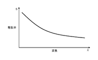
- FIG. 4 is a diagram showing the characteristics of the light scattering rate of the test object of the biological information measuring device according to the embodiment according to the light wavelength.
- FIG. 5 is a flow chart showing an example of a processing procedure by the biological information measuring device of the embodiment.
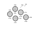
- FIG. 6 is an exemplary schematic diagram showing particles in close contact with each other in a two-dimensional image.
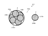
- FIG. 7 is an exemplary schematic diagram showing spaced apart particles in a two-dimensional image.
- FIG. 8 is a diagram showing an example of the correlation between the glucose concentration in the test object of the biological information measuring device of the embodiment and the total value of boundary lengths in the two-dimensional image.
- FIG. 9 shows the correlation between the total boundary length and the received light intensity detected by the detection unit when image analysis is performed on a plurality of samples for which the received light intensity is detected by the biological information measuring device of the embodiment. It is a graph which shows an example of.
- FIG. 10 is an explanatory diagram showing an example of a technique for obtaining the particle diameter from the laser diffraction/scattering method.
- FIG. 11 is an exemplary schematic configuration diagram of the biological information measuring device of the second embodiment.
- Exemplary embodiments of the present invention are disclosed below.
- the configurations of the embodiments shown below and the actions and results (effects) brought about by the configurations are examples.
- the present invention can be realized by configurations other than those disclosed in the following embodiments.
- at least one of various effects (including derivative effects) obtained by the configuration can be obtained.
- light scattering means that the particles do not have a peak at which the light transmittance decreases only at the relevant wavelength, and the transmittance increases as the wavelength becomes shorter within a range of about ⁇ 50 [nm] around the relevant wavelength. is continuously decreasing or constant. It is also the optical loss that occurs at the interface between the particles and the medium. Academically, there are reports that local absorption occurs in addition to scattering at the interface of particles such as blood cells, but it is actually extremely difficult to separate the loss that occurs at the interface from the transmitted light into scattering and absorption. Therefore, in the present specification, all losses due to particle interfaces having wavelength dependence as described above are defined as light scattering.
- the light scattering rate means the ratio of light input that is attenuated by light scattering with respect to the intensity of light input light 1, and all physical quantities that are correlated with the ratio. show.
- the scattering rate may be a Rayleigh scattering coefficient or a Mie scattering coefficient.
- FIG. 1 is a schematic configuration diagram of a biological information measurement device 100.
- the biological information measuring device 100 includes a control device 110, an irradiation section 120, a light receiving section 130, and an objective lens 131.
- the biological information measuring device 100 includes a control device 110, an irradiation section 120, a light receiving section 130, and an objective lens 131.
- the control device 110 controls each part of the biological information measuring device 100 and tests blood 210 contained in the blood vessel 201 of the living body 200 based on the test light received by the light receiving part 130.
- the glucose concentration is measured. Execute the inspection.
- Blood 210 may also be referred to as a specimen.
- Blood 210 includes plasma, blood cells, and glucose. Plasma is an example of a medium, blood cells are an example of particles, and glucose is an example of a substance of interest.
- the irradiation unit 120 irradiates the living body 200 with inspection light.
- the irradiation unit 120 has a light source device and an optical system component that transmits and emits inspection light from the light source device.
- the light-receiving unit 130 receives inspection light that is applied to the living body 200 and passes through the living body 200 , for example, inspection light that has passed through the living body 200 or reflected light that has been reflected by the living body 200 .
- the light receiving unit 130 has, for example, a CMOS image sensor, a light receiving element such as a CCD, and an optical system component that transmits inspection light to the light receiving element.
- the measurement target irradiated with the inspection light is not limited to the living body 200 itself, and may be a specimen containing components of the living body 200 .
- the objective lens 131 transmits light input from the blood 210 to the light receiving section 130 .
- the objective lens 131 can improve resolution.
- FIG. 2 is a block diagram of the biological information measuring device 100.
- the biological information measuring apparatus 100 includes an input section 140 and an output section 150 in addition to a control device 110, an irradiation section 120, and a light receiving section .
- the input unit 140 and the output unit 150 construct a user interface for users and operators.
- the input unit 140 is, for example, an input device such as a keyboard, touch panel, mouse, switch, or operation button.
- the output unit 150 is, for example, a display, a printer, a lamp, a speaker, or the like, and is an output device for images, printing, and sound.
- the control device 110 has a controller 111 , a main storage section 112 and an auxiliary storage device 113 .
- the controller 111 is, for example, a processor (circuit) such as a CPU (central processing unit).
- the main storage unit 112 is, for example, RAM (random access memory) or ROM (read only memory).
- the auxiliary storage device 113 is, for example, a non-volatile storage device such as an SSD (solid state drive) or HDD (hard disk drive).
- the controller 111 reads out programs stored in the main storage unit 112 and the auxiliary storage device 113 and executes each process to control the irradiation control unit 111a, the light reception control unit 111b, the input control unit 111c, the output control unit 111d, the detection It operates as a section 111e, a scattering rate calculation section 111f, and a concentration index calculation section 111g.
- the program can be provided as an installable file or an executable file recorded on a computer-readable recording medium.
- a recording medium may also be referred to as a program product.
- Values used in arithmetic processing by programs and processors, and information such as maps and tables may be stored in advance in the main storage unit 112 and the auxiliary storage device 113, or may be stored in the storage unit of a computer connected to a communication network. may be stored in the auxiliary storage device 113 by being downloaded via the communication network. Auxiliary storage device 113 stores data written by the processor. Also, the arithmetic processing by the controller 111 may be performed, at least in part, by hardware. In this case, the controller 111 may include, for example, an FPGA (field programmable gate array) or an ASIC (application specific integrated circuit).
- FPGA field programmable gate array
- ASIC application specific integrated circuit
- the irradiation control unit 111a controls the irradiation unit 120 so as to output predetermined inspection light.
- the light receiving control unit 111b controls the light receiving unit 130 so as to receive the inspection light.
- the input control unit 111c receives an input signal from the input unit 140. Also, the input control unit 111c may control the input unit 140 so that a predetermined input operation becomes possible.
- the output control unit 111d controls the output unit 150 to perform a predetermined output.
- the inventors conducted intensive research on the scattering of light in blood, and found that (1) almost no light is scattered at the portions where the blood cells are in contact with each other because there is no refractive index difference; (2) when the glucose concentration is low, the blood cells are in contact with each other in the blood, the interface area is small and the amount of light scattering is small, and (3) the higher the glucose concentration in the blood, the more , that the blood cells are separated from each other in the blood, the area of the interface increases, and the amount of light scattering increases accordingly. It is presumed that the blood cells are separated from each other as the glucose concentration increases because the blood cells are negatively charged.
- the controller 111 of the present embodiment includes the detection unit 111e, the scattering rate It has a calculation unit 111f and a concentration index calculation unit 111g.
- the detection unit 111e calculates the received light intensity as the total value of the luminance values of the pixels of the light receiving elements of the light receiving unit 130 .
- the scattering rate calculation unit 111f calculates the scattering rate, for example, as a ratio of the scattering intensity to the irradiation intensity.
- the illumination intensity can be considered as the sum of the transmitted or reflected intensity, the absorbed intensity and the scattered intensity. Since the received light intensity is the intensity of transmitted light or reflected light, the scattered intensity can be calculated as a value obtained by subtracting the received light intensity and the absorbed intensity from the irradiation intensity.
- the absorption intensity is the intensity of the inspection light absorbed by the living body 200, and can be estimated by a method or the like described later.
- the absorption intensity can be obtained in advance and stored in the auxiliary storage device 113, for example, as numerical values or functions in the program, or as data referred to by the program.
- the concentration index calculation unit 111g calculates a concentration index corresponding to the scattering rate calculated by the scattering rate calculation unit 111f, based on the previously obtained correlation between the scattering rate and the concentration index.
- the concentration index is a value that serves as an index of the glucose concentration, and may be the glucose concentration itself or a relative value that increases as the glucose concentration increases.
- the concentration index may be a value for each individual, or may be a value common to a plurality of people. Also, the concentration index may be a value that serves as a guideline for indicating an increase or decrease in glucose concentration in follow-up observation.
- FIG. 3 is a diagram showing an example of the correlation between the scattering rate S and the concentration index D.
- FIG. 3 As described above, the studies of the inventors have revealed that the glucose concentration increases as the scattering rate S of the test light increases. From the test results for a plurality of samples, it was found that the concentration index D corresponding to the glucose concentration can be expressed as an approximate function f(S) of the scattering rate S of the test light.
- FIG. 3 exemplifies the approximation function f(S) as a linear function, it is not limited to this.
- Such correlations are obtained in advance and stored in, for example, the auxiliary storage device 113 as functions, maps, or tables.
- the inspection light output from the irradiation unit 120 is preferably light with a wavelength that is low in absorption by the living body 200, blood 210, plasma, blood cells, and glucose.
- FIG. 4 is a graph showing an example of the wavelength characteristics of the scattering rate for an object or substance. It is considered that the wavelength characteristics of light scattering due to minute irregularities at the interface between blood cells and blood plasma do not peak at a wavelength ⁇ in the wavelength band selected as test light, as illustrated in FIG. 4 .
- the wavelength ⁇ of the inspection light is, for example, 950 [nm] or more and 1100 [nm] or less.
- the wavelength ⁇ of the inspection light is preferably 1/20 or more of the depth length (diameter) of the blood cell so that the inspection light does not optically couple with the blood cell.
- Blood cells have a diameter of about 10 [ ⁇ m].
- the irradiation unit 120 has a surface emitting element with an in-plane luminance variation of 10[%] or less as a light source device.
- the light receiving unit 130 receives an image of blood cells with a resolution that allows the diameter of the image to be determined.
- FIG. 5 is a flowchart showing an example of a processing procedure by the biological information measuring device 100.
- the controller 111 operates as an irradiation control unit 111a and a light reception control unit 111b, controls the irradiation unit 120 so as to irradiate the living body 200 with inspection light, and
- the light receiving unit 130 is controlled to receive inspection light (S1).
- the controller 111 operates as the detection section 111e and calculates the intensity of light received by the light receiving section 130 .
- the received light intensity is, for example, the total value of the luminance of each pixel of the light receiving element of the light receiving section 130 (S2).
- the controller 111 calculates the scattering rate from the received light intensity calculated by the detection unit 111e in S2 (S3).
- the controller 111 calculates a concentration index corresponding to the scattering rate calculated by the scattering rate calculator 111f in S3 based on the correlation between the scattering rate and the concentration index as shown in FIG. ).
- the controller 111 operates as the output control section 111d and controls the output section 150 to output the concentration index (S5).
- the value of the concentration index in the test may be output, or in the form of a graph showing the temporal change of the concentration index including the concentration index calculated in the past examination.
- FIGS. 6 and 7 are schematic diagrams of two-dimensional images of blood containing blood cells.
- FIG. 6 is an image showing blood cells in close contact with each other
- FIG. 7 is an image showing blood cells separated from each other. is. Although only five blood cells are included in FIGS. 6 and 7, many blood cells are included in the actual image.
- Image analysis is performed on, for example, a microscopic image of blood 210 collected on a slide as a sample, separately from measurement by biological information measuring apparatus 100 .
- the feature quantity of the image of the blood cells 210b that is, the boundary length of the interface between the blood cells and the plasma, is, for example, the length of the boundary 210b1 between the blood cells 210b and the plasma 210a in the region irradiated with light. is obtained.
- a plurality of blood cells 210b that are in close contact with each other are grouped as one cluster of regions corresponding to the blood cells, and the length of the boundary 210b1 (edge) obtained by edge detection of each group is calculated.
- the plurality of blood cells 210b as shown in FIG.
- the total value of the length of the boundary 210b1 is greater when they are separated.
- the total value is, for example, the total value of the lengths of the boundaries 210b1 obtained by image analysis within a predetermined range of the two-dimensional image.
- the area of the interface between blood cells 210b and plasma 210a decreases.
- the area of the interface between blood cells and plasma is ⁇ n ⁇ d 2 (n: number of blood cells, d: diameter of blood cells) when the blood cells are separated from each other.
- the value is obtained by subtracting the area of the portion where the blood cells are in contact with each other from the interface area ( ⁇ n ⁇ d 2 ) when the blood cells are separated.
- the diameter d of the clump where the blood cells stick to each other is obtained, the interfacial area of one clump is calculated as ⁇ D2, and the interfacial area is taken as the integrated value for the number of blood cells in the light irradiation area. can be done.
- the larger the total length of the boundary 210b1 in the image analysis the larger the area of the actual interface between the blood cell 210b and the plasma 210a, and the smaller the total length of the boundary 210b1, the smaller the actual area of the interface.
- the total value of the lengths of the boundaries 210b1 can be a parameter (feature quantity) corresponding to the area of the interface between the blood cell 210b and the plasma 210a, and can also be a parameter corresponding to the light scattering rate.
- FIG. 8 is a graph showing changes in the total length L of the boundary 210b1 obtained by image analysis when the glucose concentration in blood changes. From FIG. 8, it can be seen that as the glucose concentration increases, the blood cells 210b are separated from each other and the total length of the boundaries 210b1 obtained by image analysis increases.
- the boundary length L can be expressed as an approximate function g(Dg) of the glucose concentration Dg.
- FIG. 8 exemplifies the approximation function g(Dg) as a linear function, it is not limited to this.
- FIG. 9 shows the total value L of the lengths of all the boundaries 210b1 within the measurement range and the detected It is a graph which shows correlation with the light reception intensity detected in the part 111e.
- the total value L normalized by the blood cell count, blood cell area, blood cell density, or the like may be used.
- the received light intensity R decreases as the total length L of the boundary 210b1 increases, and the received light intensity R increases as the total length L of the boundary 210b1 decreases.
- the received light intensity R can be expressed as an approximate function h(L) of the total length L of the boundary 210b1.
- the plurality of samples shown in FIG. 9 are samples with different total lengths L of boundaries 210b1, that is, samples with different areas of interfaces between blood cells 210b and plasma 210a. It is a function obtained by regression analysis of samples.
- the difference obtained by subtracting the base received light intensity R0 from the irradiation intensity when the scattered light is minimized ( ⁇ 0) is the amount of light scattered by the living body 200, blood 210, plasma, blood cells, glucose, and other substances such as hemoglobin. It corresponds to the intensity difference due to pure absorption with the effects removed, ie the absorption intensity A. In this way the absorption intensity A can be estimated.
- the a and b corresponding to the light scattering coefficients may also change due to the action of a target substance such as glucose, and can be used as a concentration index.
- the scattering rate calculation unit 111f calculates the scattering intensity at each measurement as a value obtained by subtracting the received light intensity R obtained by the detection unit 111e at the time of measurement and the absorption intensity A (constant) from the irradiation intensity, A scattering rate can be calculated as the ratio of the scattering intensity to the irradiation intensity. According to such arithmetic processing, absorption by the living body 200, the blood 210, plasma, blood cells, glucose, and other substances can be taken into consideration, so that the scattering rate and thus the concentration index can be calculated with higher accuracy. can.
- the base received light intensity and the absorption intensity A used to calculate the scattering rate that takes absorption into account may be values obtained by examination for each individual. , an average value, a general value, an analysis value, or the like may be substituted.
- the glucose concentration can be calculated from the feature amount of the image based on the correlation between the feature amount of the image of blood cells 210b obtained by image analysis and the glucose concentration (concentration index).
- the biological information measuring apparatus 100 uses the light receiving unit 130 to obtain an image such as an electron microscope device in addition to the scattering detection optical system and light receiving element. Equipped with an optical system for analysis and a light receiving element, the controller 111 may have a feature amount calculator 111h (see FIG. 2) that calculates the feature amount of the image of the blood cell 210b by image analysis.
- the controller 111 reads the programs stored in the main storage unit 112 and the auxiliary storage device 113 and executes each process, thereby operating as the feature amount calculation unit 111h and the density index calculation unit 111g.
- the concentration index calculation unit 111g calculates a glucose concentration Dg as a concentration index corresponding to the feature amount calculated by the feature amount calculation unit 111h, using an approximate function g indicating the correlation shown in FIG. 8, a map, a table, or the like. do.
- the functions, maps, or tables are stored in the auxiliary storage device 113, for example.
- the calculation of the concentration index corresponding to the feature amount by such image analysis is based on the premise of invasive blood collection. Therefore, it is preferable to carry out in combination with the above-described noninvasive inspection based on scattering intensity.
- the feature amount of the image of the blood cells 210b in the image analysis is not limited to the total value of the length of the boundary 210b1.
- Other parameters such as the total area of the image, the density of the image of blood cells 210b in the two-dimensional image (eg, area density) may be used.
- the correlation between the feature amount of the image of blood cells 210b and each concentration index corresponds to the decrease in density of blood cells 210b in plasma 210a as the concentration of glucose increases. For example, as the concentration of glucose increases, the number of blood cells 210b in the two-dimensional image decreases, the total area of blood cells 210b in the two-dimensional image decreases, and the density of the image of blood cells 210b in the two-dimensional image decreases. become.
- a laser diffraction/scattering method can be used as a method for acquiring information about the interface area and interface boundary length of particles in a living body such as blood cells. This is a method of observing different intensity patterns depending on the angle of scattered light and obtaining the particle size distribution using the Mie scattering theory or the like, and is a technique widely used in the field of measurement.
- FIG. 10 is an explanatory diagram showing an example of a method of obtaining the diameter d of the blood cell 210b from the laser diffraction/scattering method. As shown in FIG.
- the diameter d can be calculated by approximating the clump to the particle 210p. and the length of the boundary 210b1 of the interface can be calculated.
- the interface area and the length of the interface boundary 210b1 can be calculated from the diameter d of the blood cell 210b.
- FIG. 11 is a schematic configuration diagram of a biological information measuring device 100A of the second embodiment.
- the light receiving unit 130 receives scattered light from the specimen 220 as inspection light emitted from the irradiation unit 120 and passed through the specimen 220 .
- the scattering rate calculation unit 111f see FIG. The light scattering rate can be easily calculated from the received light intensity. Subsequent processing is the same as in the first embodiment.
- the glucose concentration in the blood 210 can be calculated based on the scattering rate of the test light. According to such a configuration, the glucose concentration can be measured with higher accuracy by using the scattering rate of the test light.
- test item may be something other than blood.
- the present invention can be used for a biological information measuring device, a biological information measuring method, and a program.
- Reference numerals 100, 100A Biological information measuring device 110 Control device 111 Controller 111a Irradiation control unit 111b Light reception control unit 111c Input control unit 111d Output control unit 111e Detection unit 111f Scattering rate calculation unit 111g Concentration index calculation Unit 111h Feature amount calculation unit 112 Main storage unit 113 Auxiliary storage device 120 Irradiation unit 130 Light receiving unit 131 Objective lens 140 Input unit 150 Output unit 200 Living body 201 Blood vessel 210 Blood 210a Plasma ( medium) 210b...
Landscapes
- Health & Medical Sciences (AREA)
- Life Sciences & Earth Sciences (AREA)
- Chemical & Material Sciences (AREA)
- Physics & Mathematics (AREA)
- Engineering & Computer Science (AREA)
- General Health & Medical Sciences (AREA)
- Pathology (AREA)
- Analytical Chemistry (AREA)
- Biomedical Technology (AREA)
- Immunology (AREA)
- General Physics & Mathematics (AREA)
- Biochemistry (AREA)
- Dispersion Chemistry (AREA)
- Hematology (AREA)
- Biophysics (AREA)
- Molecular Biology (AREA)
- Signal Processing (AREA)
- Heart & Thoracic Surgery (AREA)
- Medical Informatics (AREA)
- Veterinary Medicine (AREA)
- Public Health (AREA)
- Animal Behavior & Ethology (AREA)
- Surgery (AREA)
- Optics & Photonics (AREA)
- Food Science & Technology (AREA)
- Urology & Nephrology (AREA)
- Medicinal Chemistry (AREA)
- Ecology (AREA)
- Clinical Laboratory Science (AREA)
- Chemical Kinetics & Catalysis (AREA)
- Spectroscopy & Molecular Physics (AREA)
- Emergency Medicine (AREA)
- Investigating Or Analysing Materials By Optical Means (AREA)
- Measurement Of The Respiration, Hearing Ability, Form, And Blood Characteristics Of Living Organisms (AREA)
- Investigating Or Analysing Biological Materials (AREA)
- Computer Vision & Pattern Recognition (AREA)
Priority Applications (4)
| Application Number | Priority Date | Filing Date | Title |
|---|---|---|---|
| EP22756282.4A EP4296668A4 (en) | 2021-02-18 | 2022-02-17 | Biological information measurement device, biological information measurement method, and program |
| JP2023500934A JPWO2022176965A1 (https=) | 2021-02-18 | 2022-02-17 | |
| CN202280015154.0A CN116867433A (zh) | 2021-02-18 | 2022-02-17 | 生物体信息测定装置、生物体信息测定方法以及程序 |
| US18/450,628 US20230393117A1 (en) | 2021-02-18 | 2023-08-16 | Biological information measurement device, biological information measurement method, and computer-readable recording medium |
Applications Claiming Priority (2)
| Application Number | Priority Date | Filing Date | Title |
|---|---|---|---|
| JP2021-024344 | 2021-02-18 | ||
| JP2021024344 | 2021-02-18 |
Related Child Applications (1)
| Application Number | Title | Priority Date | Filing Date |
|---|---|---|---|
| US18/450,628 Continuation US20230393117A1 (en) | 2021-02-18 | 2023-08-16 | Biological information measurement device, biological information measurement method, and computer-readable recording medium |
Publications (1)
| Publication Number | Publication Date |
|---|---|
| WO2022176965A1 true WO2022176965A1 (ja) | 2022-08-25 |
Family
ID=82930722
Family Applications (1)
| Application Number | Title | Priority Date | Filing Date |
|---|---|---|---|
| PCT/JP2022/006499 Ceased WO2022176965A1 (ja) | 2021-02-18 | 2022-02-17 | 生体情報測定装置、生体情報測定方法、およびプログラム |
Country Status (6)
| Country | Link |
|---|---|
| US (1) | US20230393117A1 (https=) |
| EP (1) | EP4296668A4 (https=) |
| JP (1) | JPWO2022176965A1 (https=) |
| CN (1) | CN116867433A (https=) |
| TW (1) | TW202242408A (https=) |
| WO (1) | WO2022176965A1 (https=) |
Citations (5)
| Publication number | Priority date | Publication date | Assignee | Title |
|---|---|---|---|---|
| JP2005106592A (ja) | 2003-09-30 | 2005-04-21 | Aime Technology Co Ltd | 血糖測定法およびその装置 |
| JP2006122579A (ja) * | 2004-11-01 | 2006-05-18 | Aime Technology Co Ltd | 散乱媒質中微量成分濃度の無侵襲測定法およびその装置 |
| JP2008253455A (ja) * | 2007-04-03 | 2008-10-23 | Shimadzu Corp | 飲酒検知装置 |
| WO2013094362A1 (ja) * | 2011-12-19 | 2013-06-27 | ソニー株式会社 | 測定装置、測定方法、プログラム及び記録媒体 |
| JP2017220926A (ja) * | 2016-06-07 | 2017-12-14 | パナソニックIpマネジメント株式会社 | 撮像装置 |
Family Cites Families (7)
| Publication number | Priority date | Publication date | Assignee | Title |
|---|---|---|---|---|
| US6329139B1 (en) * | 1995-04-25 | 2001-12-11 | Discovery Partners International | Automated sorting system for matrices with memory |
| DE602005027907D1 (de) * | 2004-12-13 | 2011-06-16 | Bayer Healthcare Llc | Transmissionspektroskopiesystem zur verwendung bei der bestimmung von analyten in körperflüssigkeit |
| KR101040653B1 (ko) * | 2009-01-21 | 2011-06-10 | 서울대학교산학협력단 | 비접촉 광용적맥파 측정장치와 이를 이용한 산소포화도 측정장치 및 혈압 측정장치 |
| CN103347550A (zh) * | 2010-11-17 | 2013-10-09 | 弗雷泽纽斯医疗保健控股公司 | 用于光学监视系统的传感器夹组件 |
| JP6241853B2 (ja) * | 2012-12-06 | 2017-12-06 | 国立大学法人北海道大学 | 非侵襲型生体脂質濃度計測器、非侵襲型生体脂質代謝機能計測器、非侵襲による生体脂質濃度計測方法および非侵襲による生体脂質代謝機能検査方法 |
| KR101512076B1 (ko) * | 2014-04-29 | 2015-04-14 | 길영준 | 다중 생체신호를 이용한 혈당 측정 방법 및 혈당 측정 장치 |
| US10506989B2 (en) * | 2014-09-05 | 2019-12-17 | Phc Holdings Corporation | Method for quantifying glucose concentration and glucose concentration measurement device |
-
2022
- 2022-02-16 TW TW111105555A patent/TW202242408A/zh unknown
- 2022-02-17 EP EP22756282.4A patent/EP4296668A4/en active Pending
- 2022-02-17 WO PCT/JP2022/006499 patent/WO2022176965A1/ja not_active Ceased
- 2022-02-17 JP JP2023500934A patent/JPWO2022176965A1/ja active Pending
- 2022-02-17 CN CN202280015154.0A patent/CN116867433A/zh active Pending
-
2023
- 2023-08-16 US US18/450,628 patent/US20230393117A1/en active Pending
Patent Citations (5)
| Publication number | Priority date | Publication date | Assignee | Title |
|---|---|---|---|---|
| JP2005106592A (ja) | 2003-09-30 | 2005-04-21 | Aime Technology Co Ltd | 血糖測定法およびその装置 |
| JP2006122579A (ja) * | 2004-11-01 | 2006-05-18 | Aime Technology Co Ltd | 散乱媒質中微量成分濃度の無侵襲測定法およびその装置 |
| JP2008253455A (ja) * | 2007-04-03 | 2008-10-23 | Shimadzu Corp | 飲酒検知装置 |
| WO2013094362A1 (ja) * | 2011-12-19 | 2013-06-27 | ソニー株式会社 | 測定装置、測定方法、プログラム及び記録媒体 |
| JP2017220926A (ja) * | 2016-06-07 | 2017-12-14 | パナソニックIpマネジメント株式会社 | 撮像装置 |
Non-Patent Citations (1)
| Title |
|---|
| See also references of EP4296668A4 |
Also Published As
| Publication number | Publication date |
|---|---|
| JPWO2022176965A1 (https=) | 2022-08-25 |
| US20230393117A1 (en) | 2023-12-07 |
| CN116867433A (zh) | 2023-10-10 |
| EP4296668A4 (en) | 2025-05-07 |
| EP4296668A1 (en) | 2023-12-27 |
| TW202242408A (zh) | 2022-11-01 |
Similar Documents
| Publication | Publication Date | Title |
|---|---|---|
| JP6559555B2 (ja) | 光計測方法および装置 | |
| KR102479862B1 (ko) | 입자 분석 방법 | |
| JP6798625B2 (ja) | 定量位相画像生成方法、定量位相画像生成装置およびプログラム | |
| US8280494B2 (en) | Apparatus and method to measure a spectroscopic characteristic in an object | |
| JP6001566B2 (ja) | 赤血球に関連付けられた物理パラメータの決定方法及び装置 | |
| KR102042864B1 (ko) | 혼탁 매질에서의 흡광 계수를 결정하기 위한 방법 | |
| JP2009534083A (ja) | 光学測定装置 | |
| JP6936144B2 (ja) | 粒子特性評価方法及び装置 | |
| WO2004111621A1 (en) | Analysis apparatus and method comprising auto-focusing means | |
| JP5590541B2 (ja) | 鮮度評価装置及び鮮度評価方法 | |
| JP6864313B2 (ja) | 化学物質の評価方法 | |
| RU2610942C1 (ru) | Способ оптического измерения счетной концентрации дисперсных частиц в жидких средах и устройство для его осуществления | |
| JP6886464B2 (ja) | 試料媒質の波長依存性屈折率を決定するための光学顕微鏡及び方法 | |
| Gao | Fourier spectrum analysis of full-field optical coherence tomography for tissue imaging | |
| WO2016166847A1 (ja) | 観察装置 | |
| JPH0933423A (ja) | 縦型レーザ回折式粒度分布測定装置 | |
| WO2022176965A1 (ja) | 生体情報測定装置、生体情報測定方法、およびプログラム | |
| JP2012194165A (ja) | 走査型顕微光散乱測定解析装置および光散乱解析方法 | |
| RU2361190C1 (ru) | Способ определения концентрации наночастиц | |
| JP2021039119A (ja) | 定量位相画像生成装置 | |
| JP2000002644A (ja) | レーザ回折・散乱式粒度分布測定装置 | |
| JP7322683B2 (ja) | 画像処理方法、画像生成装置及び画像処理システム | |
| JP2981699B2 (ja) | 検体の3次元情報計測方法および装置 | |
| JPH10221248A (ja) | 光学的検査方法及び光学的検査装置 | |
| Dasore et al. | Backscattering Imaging |
Legal Events
| Date | Code | Title | Description |
|---|---|---|---|
| 121 | Ep: the epo has been informed by wipo that ep was designated in this application |
Ref document number: 22756282 Country of ref document: EP Kind code of ref document: A1 |
|
| WWE | Wipo information: entry into national phase |
Ref document number: 202280015154.0 Country of ref document: CN |
|
| WWE | Wipo information: entry into national phase |
Ref document number: 2023500934 Country of ref document: JP |
|
| WWE | Wipo information: entry into national phase |
Ref document number: 2022756282 Country of ref document: EP |
|
| NENP | Non-entry into the national phase |
Ref country code: DE |
|
| ENP | Entry into the national phase |
Ref document number: 2022756282 Country of ref document: EP Effective date: 20230918 |