WO2022176771A1 - 回転電機及びその製造方法 - Google Patents
回転電機及びその製造方法 Download PDFInfo
- Publication number
- WO2022176771A1 WO2022176771A1 PCT/JP2022/005326 JP2022005326W WO2022176771A1 WO 2022176771 A1 WO2022176771 A1 WO 2022176771A1 JP 2022005326 W JP2022005326 W JP 2022005326W WO 2022176771 A1 WO2022176771 A1 WO 2022176771A1
- Authority
- WO
- WIPO (PCT)
- Prior art keywords
- magnet
- sintered body
- axis
- magnets
- electric machine
- Prior art date
- Legal status (The legal status is an assumption and is not a legal conclusion. Google has not performed a legal analysis and makes no representation as to the accuracy of the status listed.)
- Ceased
Links
Images






Classifications
-
- H—ELECTRICITY
- H02—GENERATION; CONVERSION OR DISTRIBUTION OF ELECTRIC POWER
- H02K—DYNAMO-ELECTRIC MACHINES
- H02K1/00—Details of the magnetic circuit
- H02K1/06—Details of the magnetic circuit characterised by the shape, form or construction
- H02K1/22—Rotating parts of the magnetic circuit
- H02K1/27—Rotor cores with permanent magnets
- H02K1/2706—Inner rotors
- H02K1/272—Inner rotors the magnetisation axis of the magnets being perpendicular to the rotor axis
- H02K1/274—Inner rotors the magnetisation axis of the magnets being perpendicular to the rotor axis the rotor consisting of two or more circumferentially positioned magnets
- H02K1/2753—Inner rotors the magnetisation axis of the magnets being perpendicular to the rotor axis the rotor consisting of two or more circumferentially positioned magnets the rotor consisting of magnets or groups of magnets arranged with alternating polarity
- H02K1/276—Magnets embedded in the magnetic core, e.g. interior permanent magnets [IPM]
-
- H—ELECTRICITY
- H02—GENERATION; CONVERSION OR DISTRIBUTION OF ELECTRIC POWER
- H02K—DYNAMO-ELECTRIC MACHINES
- H02K15/00—Processes or apparatus specially adapted for manufacturing, assembling, maintaining or repairing of dynamo-electric machines
- H02K15/02—Processes or apparatus specially adapted for manufacturing, assembling, maintaining or repairing of dynamo-electric machines of stator or rotor bodies
- H02K15/03—Processes or apparatus specially adapted for manufacturing, assembling, maintaining or repairing of dynamo-electric machines of stator or rotor bodies having permanent magnets
-
- H—ELECTRICITY
- H02—GENERATION; CONVERSION OR DISTRIBUTION OF ELECTRIC POWER
- H02K—DYNAMO-ELECTRIC MACHINES
- H02K1/00—Details of the magnetic circuit
- H02K1/02—Details of the magnetic circuit characterised by the magnetic material
-
- H—ELECTRICITY
- H02—GENERATION; CONVERSION OR DISTRIBUTION OF ELECTRIC POWER
- H02K—DYNAMO-ELECTRIC MACHINES
- H02K15/00—Processes or apparatus specially adapted for manufacturing, assembling, maintaining or repairing of dynamo-electric machines
- H02K15/12—Impregnating, moulding insulation, heating or drying of windings, stators, rotors or machines
-
- H—ELECTRICITY
- H02—GENERATION; CONVERSION OR DISTRIBUTION OF ELECTRIC POWER
- H02K—DYNAMO-ELECTRIC MACHINES
- H02K2201/00—Specific aspects not provided for in the other groups of this subclass relating to the magnetic circuits
- H02K2201/09—Magnetic cores comprising laminations characterised by being fastened by caulking
-
- H—ELECTRICITY
- H02—GENERATION; CONVERSION OR DISTRIBUTION OF ELECTRIC POWER
- H02K—DYNAMO-ELECTRIC MACHINES
- H02K2213/00—Specific aspects, not otherwise provided for and not covered by codes H02K2201/00 - H02K2211/00
- H02K2213/03—Machines characterised by numerical values, ranges, mathematical expressions or similar information
Definitions
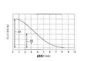
- Coercive force distribution in the direction from the surface of the sintered body toward the inside was investigated in the case where the sintered body was subjected to grain boundary diffusion treatment by attaching a deposit to one flat surface of the surface of the sintered body. .
- the thickness dimension of the sintered body is set to 16 mm or less.
- the heavy rare earth element can be more preferably diffused inside the sintered body.
- said field element has a field element core to which said magnet is attached,
- the magnets are oriented so that the direction of the easy magnetization axis on the d-axis side, which is the magnetic pole center, is closer to the direction of the d-axis than the direction of the easy magnetization axis on the q-axis side, which is the magnetic pole boundary, At least a portion of the q-axis core portion forming the field core is magnetically saturated by the magnetic flux of the magnet.
- FIG. 1 is a vertical cross-sectional view of a rotating electric machine according to the first embodiment
- FIG. 2 is a cross-sectional view of a rotating electric machine
- FIG. 3 is a cross-sectional view of the rotor and stator
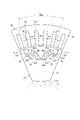
- FIG. 4 is a diagram showing the configuration of the magnet
- FIG. 5 is a diagram showing a magnet orientation technique
- FIG. 6 is a flow chart showing the manufacturing process of the magnet
- FIG. 7 is a perspective view showing a sintered body of magnet powder
- FIG. 8 is a diagram showing the effect of grain boundary diffusion treatment
- the stator 30 functions as one magnetic pole (N pole or S pole) when the stator winding 33 is energized.
- Wt2, Wt3 and Wt4 correspond to the circumferential width dimension of the teeth 34, and Wt1 and Wt5 correspond to half of the circumferential width dimension of the teeth 34.
- Wt1 and Wt5 correspond to half of the circumferential width dimension of the teeth 34.
- step S12 the sintered body 50 is subjected to grain boundary diffusion treatment. More specifically, first, deposits are made to adhere to the surface of the sintered body 50 .
- deposits are made to adhere to the surface of the sintered body 50 .
- the pair of flat surfaces 50a two surfaces of the surfaces (six surfaces) of the sintered body 50 are adhered by the adhesion device.
- one of the pair of flat surfaces 50a to which the adhering matter adheres is indicated by hatching.
- the deposit may be, for example, a belt-like or sheet-like object containing the oxide powder, the fluoride powder, or the alloy powder.
- the stator 130 has a stator core 131 .
- the stator core 131 is configured as a core sheet laminated body in which core sheets made of magnetic steel sheets, which are magnetic materials, are laminated in the axial direction, and has a cylindrical shape with a predetermined thickness in the radial direction.
- a stator winding 133 is assembled on the radially outer side of the stator core 131 on the rotor 120 side.
- the outer peripheral surface of the stator core 131 has a curved surface without unevenness.
- the stator core 131 functions as a back yoke.
- the stator core 131 is configured by laminating a plurality of core sheets, which are punched into, for example, an annular plate shape, in the axial direction. However, a stator core 131 having a helical core structure may be used.
- stator 130 In the stator 130, a member between conductors is provided between conductor portions in the circumferential direction, and a non-magnetic material is used as the member between conductors.
- the stator 130 has a configuration in which no member between conductors is provided between the conductors in the circumferential direction.
- the magnetic flux of the magnet 123 causes at least a portion (specifically, for example, a portion on the magnet 123 side in the radial direction) of the q-axis core portion 121q (see FIG. 10) constituting the rotor core 121 to become magnetic. saturated.
- the q-axis core portion 121q is a portion of the rotor core 121 that straddles the q-axis.
- the magnetic permeability of the magnetically saturated portion of the q-axis core portion 121q is lowered, and the inductance is lowered.
- the amount of magnetic flux generated by energization of the stator winding 133 interlinking the magnet 123 can be reduced.
- the occurrence of eddy current loss in the magnet 123 can be suppressed.
Landscapes
- Engineering & Computer Science (AREA)
- Power Engineering (AREA)
- Manufacturing & Machinery (AREA)
- Permanent Field Magnets Of Synchronous Machinery (AREA)
Priority Applications (4)
| Application Number | Priority Date | Filing Date | Title |
|---|---|---|---|
| DE112022001098.3T DE112022001098T5 (de) | 2021-02-17 | 2022-02-10 | Elektrische Drehmaschine und Verfahren zu deren Herstellung |
| JP2023500799A JP7681092B2 (ja) | 2021-02-17 | 2022-02-10 | 回転電機及びその製造方法 |
| CN202280014659.5A CN116868490A (zh) | 2021-02-17 | 2022-02-10 | 旋转电机及其制造方法 |
| US18/450,307 US12519354B2 (en) | 2021-02-17 | 2023-08-15 | Rotary electric machine and manufacturing method therefor |
Applications Claiming Priority (2)
| Application Number | Priority Date | Filing Date | Title |
|---|---|---|---|
| JP2021-023752 | 2021-02-17 | ||
| JP2021023752 | 2021-02-17 |
Related Child Applications (1)
| Application Number | Title | Priority Date | Filing Date |
|---|---|---|---|
| US18/450,307 Continuation US12519354B2 (en) | 2021-02-17 | 2023-08-15 | Rotary electric machine and manufacturing method therefor |
Publications (1)
| Publication Number | Publication Date |
|---|---|
| WO2022176771A1 true WO2022176771A1 (ja) | 2022-08-25 |
Family
ID=82931649
Family Applications (1)
| Application Number | Title | Priority Date | Filing Date |
|---|---|---|---|
| PCT/JP2022/005326 Ceased WO2022176771A1 (ja) | 2021-02-17 | 2022-02-10 | 回転電機及びその製造方法 |
Country Status (5)
| Country | Link |
|---|---|
| US (1) | US12519354B2 (https=) |
| JP (1) | JP7681092B2 (https=) |
| CN (1) | CN116868490A (https=) |
| DE (1) | DE112022001098T5 (https=) |
| WO (1) | WO2022176771A1 (https=) |
Citations (4)
| Publication number | Priority date | Publication date | Assignee | Title |
|---|---|---|---|---|
| JP2007258455A (ja) * | 2006-03-23 | 2007-10-04 | Hitachi Metals Ltd | R−Fe−B系希土類焼結磁石およびその製造方法 |
| JP2018107899A (ja) * | 2016-12-26 | 2018-07-05 | 株式会社東芝 | 回転子 |
| JP2018148754A (ja) * | 2017-03-08 | 2018-09-20 | Tdk株式会社 | 磁石積層体およびモータ |
| JP2020039240A (ja) * | 2018-09-05 | 2020-03-12 | 株式会社デンソー | 回転電機 |
Family Cites Families (13)
| Publication number | Priority date | Publication date | Assignee | Title |
|---|---|---|---|---|
| US6936945B2 (en) | 2000-06-14 | 2005-08-30 | Matsushita Electric Industrial Co., Ltd. | Permanent magnet synchronous motor |
| JP5251219B2 (ja) | 2008-04-04 | 2013-07-31 | 信越化学工業株式会社 | 永久磁石式回転機用回転子 |
| JP2010022147A (ja) * | 2008-07-11 | 2010-01-28 | Hitachi Ltd | 焼結磁石モータ |
| JP5493663B2 (ja) * | 2009-10-01 | 2014-05-14 | 信越化学工業株式会社 | Ipm型永久磁石回転機用回転子の組立方法 |
| JP2013243886A (ja) * | 2012-05-22 | 2013-12-05 | Nitto Denko Corp | 永久磁石モータ、永久磁石モータの製造方法及び永久磁石 |
| JP6784484B2 (ja) * | 2015-09-11 | 2020-11-11 | Tdk株式会社 | R−t−b系焼結磁石およびモータ |
| JP6759649B2 (ja) * | 2016-03-23 | 2020-09-23 | Tdk株式会社 | 希土類磁石及びモーター |
| US11843334B2 (en) * | 2017-07-13 | 2023-12-12 | Denso Corporation | Rotating electrical machine |
| CN113991958A (zh) | 2017-07-21 | 2022-01-28 | 株式会社电装 | 旋转电机 |
| JP2019024293A (ja) | 2017-07-21 | 2019-02-14 | 株式会社デンソー | 回転電機 |
| DE112018003942T5 (de) | 2017-08-01 | 2020-05-07 | Denso Corporation | Magnetische Erzeugungseinrichtung für einen Motor, Weichmagnetischer Kern und Verfahren zur Herstellung eines Magneten |
| WO2019026979A1 (ja) | 2017-08-01 | 2019-02-07 | 株式会社デンソー | 回転電機、回転電機駆動システム、磁石、磁石の製造方法、着磁装置、及び磁石ユニット |
| JP7423932B2 (ja) | 2019-08-09 | 2024-01-30 | 株式会社三洋物産 | 遊技機 |
-
2022
- 2022-02-10 JP JP2023500799A patent/JP7681092B2/ja active Active
- 2022-02-10 WO PCT/JP2022/005326 patent/WO2022176771A1/ja not_active Ceased
- 2022-02-10 DE DE112022001098.3T patent/DE112022001098T5/de active Pending
- 2022-02-10 CN CN202280014659.5A patent/CN116868490A/zh active Pending
-
2023
- 2023-08-15 US US18/450,307 patent/US12519354B2/en active Active
Patent Citations (4)
| Publication number | Priority date | Publication date | Assignee | Title |
|---|---|---|---|---|
| JP2007258455A (ja) * | 2006-03-23 | 2007-10-04 | Hitachi Metals Ltd | R−Fe−B系希土類焼結磁石およびその製造方法 |
| JP2018107899A (ja) * | 2016-12-26 | 2018-07-05 | 株式会社東芝 | 回転子 |
| JP2018148754A (ja) * | 2017-03-08 | 2018-09-20 | Tdk株式会社 | 磁石積層体およびモータ |
| JP2020039240A (ja) * | 2018-09-05 | 2020-03-12 | 株式会社デンソー | 回転電機 |
Also Published As
| Publication number | Publication date |
|---|---|
| JP7681092B2 (ja) | 2025-05-21 |
| CN116868490A (zh) | 2023-10-10 |
| JPWO2022176771A1 (https=) | 2022-08-25 |
| DE112022001098T5 (de) | 2023-12-14 |
| US12519354B2 (en) | 2026-01-06 |
| US20240039349A1 (en) | 2024-02-01 |
Similar Documents
| Publication | Publication Date | Title |
|---|---|---|
| TWI517526B (zh) | 永久磁體機 | |
| US8659199B2 (en) | Axial gap permanent magnet motor, rotor used for the same, and production method of the rotor | |
| JP4096843B2 (ja) | モータ及びその製造方法 | |
| US7228616B2 (en) | System and method for magnetization of permanent magnet rotors in electrical machines | |
| CN108475971B (zh) | 磁化方法、转子、电动机以及涡旋压缩机 | |
| JP2013126281A (ja) | 界磁子の製造方法及び界磁子用の端板 | |
| JP2008193778A (ja) | 固定子及び密閉型圧縮機及び回転機 | |
| CN108475972A (zh) | 转子、磁化方法、电动机以及涡旋压缩机 | |
| JPH11136890A (ja) | 永久磁石式リラクタンス型回転電機 | |
| JP7426569B1 (ja) | 表面磁石型同期機、その回転子および回転子の製造方法 | |
| JP2016144322A (ja) | 回転電機用ロータおよびその製造方法 | |
| JP2010183692A (ja) | モータ用磁石とipmモータ用ロータ、およびipmモータ | |
| CN108028563B (zh) | 电动助力转向用永磁体电动机 | |
| JP2017229192A (ja) | 回転電機および回転電機の製造方法 | |
| WO2022176771A1 (ja) | 回転電機及びその製造方法 | |
| JP2004064887A (ja) | 永久磁石電動機 | |
| JP2016082798A (ja) | 回転電機用ロータとその製造装置およびそれを用いた製造方法 | |
| CN107046352B (zh) | 内部永磁电机 | |
| JP2001025191A (ja) | 電動機のロータ及びその製造方法 | |
| JP7810974B2 (ja) | ブラシレスspmモータおよびその回転子の製造方法 | |
| CN107404170A (zh) | 永磁电机及其转子结构 | |
| US20230283126A1 (en) | Rotating electric machine rotor and rotating electric machine | |
| JP6330425B2 (ja) | 回転電気機械 | |
| CN210780276U (zh) | 一种混合励磁电机新型转子结构 | |
| JP2025062628A (ja) | ブラシレスspmモータおよびその回転子の製造方法 |
Legal Events
| Date | Code | Title | Description |
|---|---|---|---|
| 121 | Ep: the epo has been informed by wipo that ep was designated in this application |
Ref document number: 22756091 Country of ref document: EP Kind code of ref document: A1 |
|
| ENP | Entry into the national phase |
Ref document number: 2023500799 Country of ref document: JP Kind code of ref document: A |
|
| WWE | Wipo information: entry into national phase |
Ref document number: 202280014659.5 Country of ref document: CN |
|
| WWE | Wipo information: entry into national phase |
Ref document number: 112022001098 Country of ref document: DE |
|
| 122 | Ep: pct application non-entry in european phase |
Ref document number: 22756091 Country of ref document: EP Kind code of ref document: A1 |