WO2022168817A1 - 緩衝器 - Google Patents
緩衝器 Download PDFInfo
- Publication number
- WO2022168817A1 WO2022168817A1 PCT/JP2022/003732 JP2022003732W WO2022168817A1 WO 2022168817 A1 WO2022168817 A1 WO 2022168817A1 JP 2022003732 W JP2022003732 W JP 2022003732W WO 2022168817 A1 WO2022168817 A1 WO 2022168817A1
- Authority
- WO
- WIPO (PCT)
- Prior art keywords
- disk
- low
- passage
- rigidity
- valve
- Prior art date
- Legal status (The legal status is an assumption and is not a legal conclusion. Google has not performed a legal analysis and makes no representation as to the accuracy of the status listed.)
- Ceased
Links
Images





Classifications
-
- F—MECHANICAL ENGINEERING; LIGHTING; HEATING; WEAPONS; BLASTING
- F16—ENGINEERING ELEMENTS AND UNITS; GENERAL MEASURES FOR PRODUCING AND MAINTAINING EFFECTIVE FUNCTIONING OF MACHINES OR INSTALLATIONS; THERMAL INSULATION IN GENERAL
- F16F—SPRINGS; SHOCK-ABSORBERS; MEANS FOR DAMPING VIBRATION
- F16F9/00—Springs, vibration-dampers, shock-absorbers, or similarly-constructed movement-dampers using a fluid or the equivalent as damping medium
- F16F9/32—Details
- F16F9/44—Means on or in the damper for manual or non-automatic adjustment; such means combined with temperature correction
- F16F9/46—Means on or in the damper for manual or non-automatic adjustment; such means combined with temperature correction allowing control from a distance, i.e. location of means for control input being remote from site of valves, e.g. on damper external wall
- F16F9/465—Means on or in the damper for manual or non-automatic adjustment; such means combined with temperature correction allowing control from a distance, i.e. location of means for control input being remote from site of valves, e.g. on damper external wall using servo control, the servo pressure being created by the flow of damping fluid, e.g. controlling pressure in a chamber downstream of a pilot passage
-
- F—MECHANICAL ENGINEERING; LIGHTING; HEATING; WEAPONS; BLASTING
- F16—ENGINEERING ELEMENTS AND UNITS; GENERAL MEASURES FOR PRODUCING AND MAINTAINING EFFECTIVE FUNCTIONING OF MACHINES OR INSTALLATIONS; THERMAL INSULATION IN GENERAL
- F16F—SPRINGS; SHOCK-ABSORBERS; MEANS FOR DAMPING VIBRATION
- F16F9/00—Springs, vibration-dampers, shock-absorbers, or similarly-constructed movement-dampers using a fluid or the equivalent as damping medium
- F16F9/10—Springs, vibration-dampers, shock-absorbers, or similarly-constructed movement-dampers using a fluid or the equivalent as damping medium using liquid only; using a fluid of which the nature is immaterial
- F16F9/14—Devices with one or more members, e.g. pistons, vanes, moving to and fro in chambers and using throttling effect
- F16F9/16—Devices with one or more members, e.g. pistons, vanes, moving to and fro in chambers and using throttling effect involving only straight-line movement of the effective parts
- F16F9/18—Devices with one or more members, e.g. pistons, vanes, moving to and fro in chambers and using throttling effect involving only straight-line movement of the effective parts with a closed cylinder and a piston separating two or more working spaces therein
- F16F9/19—Devices with one or more members, e.g. pistons, vanes, moving to and fro in chambers and using throttling effect involving only straight-line movement of the effective parts with a closed cylinder and a piston separating two or more working spaces therein with a single cylinder and of single-tube type
-
- F—MECHANICAL ENGINEERING; LIGHTING; HEATING; WEAPONS; BLASTING
- F16—ENGINEERING ELEMENTS AND UNITS; GENERAL MEASURES FOR PRODUCING AND MAINTAINING EFFECTIVE FUNCTIONING OF MACHINES OR INSTALLATIONS; THERMAL INSULATION IN GENERAL
- F16F—SPRINGS; SHOCK-ABSORBERS; MEANS FOR DAMPING VIBRATION
- F16F9/00—Springs, vibration-dampers, shock-absorbers, or similarly-constructed movement-dampers using a fluid or the equivalent as damping medium
- F16F9/32—Details
- F16F9/34—Special valve constructions; Shape or construction of throttling passages
- F16F9/348—Throttling passages in the form of annular discs or other plate-like elements which may or may not have a spring action, operating in opposite directions or singly, e.g. annular discs positioned on top of the valve or piston body
-
- F—MECHANICAL ENGINEERING; LIGHTING; HEATING; WEAPONS; BLASTING
- F16—ENGINEERING ELEMENTS AND UNITS; GENERAL MEASURES FOR PRODUCING AND MAINTAINING EFFECTIVE FUNCTIONING OF MACHINES OR INSTALLATIONS; THERMAL INSULATION IN GENERAL
- F16F—SPRINGS; SHOCK-ABSORBERS; MEANS FOR DAMPING VIBRATION
- F16F9/00—Springs, vibration-dampers, shock-absorbers, or similarly-constructed movement-dampers using a fluid or the equivalent as damping medium
- F16F9/32—Details
- F16F9/34—Special valve constructions; Shape or construction of throttling passages
- F16F9/348—Throttling passages in the form of annular discs or other plate-like elements which may or may not have a spring action, operating in opposite directions or singly, e.g. annular discs positioned on top of the valve or piston body
- F16F9/3484—Throttling passages in the form of annular discs or other plate-like elements which may or may not have a spring action, operating in opposite directions or singly, e.g. annular discs positioned on top of the valve or piston body characterised by features of the annular discs per se, singularly or in combination
-
- F—MECHANICAL ENGINEERING; LIGHTING; HEATING; WEAPONS; BLASTING
- F16—ENGINEERING ELEMENTS AND UNITS; GENERAL MEASURES FOR PRODUCING AND MAINTAINING EFFECTIVE FUNCTIONING OF MACHINES OR INSTALLATIONS; THERMAL INSULATION IN GENERAL
- F16F—SPRINGS; SHOCK-ABSORBERS; MEANS FOR DAMPING VIBRATION
- F16F9/00—Springs, vibration-dampers, shock-absorbers, or similarly-constructed movement-dampers using a fluid or the equivalent as damping medium
- F16F9/32—Details
- F16F9/34—Special valve constructions; Shape or construction of throttling passages
- F16F9/348—Throttling passages in the form of annular discs or other plate-like elements which may or may not have a spring action, operating in opposite directions or singly, e.g. annular discs positioned on top of the valve or piston body
- F16F9/3488—Throttling passages in the form of annular discs or other plate-like elements which may or may not have a spring action, operating in opposite directions or singly, e.g. annular discs positioned on top of the valve or piston body characterised by features intended to affect valve bias or pre-stress
-
- F—MECHANICAL ENGINEERING; LIGHTING; HEATING; WEAPONS; BLASTING
- F16—ENGINEERING ELEMENTS AND UNITS; GENERAL MEASURES FOR PRODUCING AND MAINTAINING EFFECTIVE FUNCTIONING OF MACHINES OR INSTALLATIONS; THERMAL INSULATION IN GENERAL
- F16F—SPRINGS; SHOCK-ABSORBERS; MEANS FOR DAMPING VIBRATION
- F16F9/00—Springs, vibration-dampers, shock-absorbers, or similarly-constructed movement-dampers using a fluid or the equivalent as damping medium
- F16F9/32—Details
- F16F9/44—Means on or in the damper for manual or non-automatic adjustment; such means combined with temperature correction
- F16F9/46—Means on or in the damper for manual or non-automatic adjustment; such means combined with temperature correction allowing control from a distance, i.e. location of means for control input being remote from site of valves, e.g. on damper external wall
-
- F—MECHANICAL ENGINEERING; LIGHTING; HEATING; WEAPONS; BLASTING
- F16—ENGINEERING ELEMENTS AND UNITS; GENERAL MEASURES FOR PRODUCING AND MAINTAINING EFFECTIVE FUNCTIONING OF MACHINES OR INSTALLATIONS; THERMAL INSULATION IN GENERAL
- F16F—SPRINGS; SHOCK-ABSORBERS; MEANS FOR DAMPING VIBRATION
- F16F9/00—Springs, vibration-dampers, shock-absorbers, or similarly-constructed movement-dampers using a fluid or the equivalent as damping medium
- F16F9/32—Details
- F16F9/48—Arrangements for providing different damping effects at different parts of the stroke
-
- F—MECHANICAL ENGINEERING; LIGHTING; HEATING; WEAPONS; BLASTING
- F16—ENGINEERING ELEMENTS AND UNITS; GENERAL MEASURES FOR PRODUCING AND MAINTAINING EFFECTIVE FUNCTIONING OF MACHINES OR INSTALLATIONS; THERMAL INSULATION IN GENERAL
- F16F—SPRINGS; SHOCK-ABSORBERS; MEANS FOR DAMPING VIBRATION
- F16F9/00—Springs, vibration-dampers, shock-absorbers, or similarly-constructed movement-dampers using a fluid or the equivalent as damping medium
- F16F9/32—Details
- F16F9/50—Special means providing automatic damping adjustment, i.e. self-adjustment of damping by particular sliding movements of a valve element, other than flexions or displacement of valve discs; Special means providing self-adjustment of spring characteristics
- F16F9/516—Special means providing automatic damping adjustment, i.e. self-adjustment of damping by particular sliding movements of a valve element, other than flexions or displacement of valve discs; Special means providing self-adjustment of spring characteristics resulting in the damping effects during contraction being different from the damping effects during extension, i.e. responsive to the direction of movement
-
- F—MECHANICAL ENGINEERING; LIGHTING; HEATING; WEAPONS; BLASTING
- F16—ENGINEERING ELEMENTS AND UNITS; GENERAL MEASURES FOR PRODUCING AND MAINTAINING EFFECTIVE FUNCTIONING OF MACHINES OR INSTALLATIONS; THERMAL INSULATION IN GENERAL
- F16F—SPRINGS; SHOCK-ABSORBERS; MEANS FOR DAMPING VIBRATION
- F16F2230/00—Purpose; Design features
- F16F2230/36—Holes, slots or the like
Definitions
- the present invention relates to a damping force adjustable shock absorber that controls the flow of working fluid with respect to the stroke of a piston rod to adjust the damping force.
- the low-rigidity disc when low-rigidity discs are used, if the pressure in the cylinder upper chamber becomes higher than the pressure in the compression-side back pressure chamber during the extension stroke, for example, the low-rigidity disc seated on the seat portion and the disc adjacent to the low-rigidity disc As a result, the low-rigidity disc may be deformed and the durability may be impaired.
- An object of the present invention is to provide a shock absorber with improved durability.
- the shock absorber of the present invention includes a cylinder in which a working fluid is sealed, a piston movably provided in the cylinder and partitioning the inside of the cylinder into two chambers, one end connected to the piston, and the other end to the piston.
- a piston rod extending to the outside of a cylinder, a passage through which a working fluid flows when the piston moves in one direction, a passage forming member in which the passage is formed, and working fluid passing through the passage forming member.
- a main valve that applies resistance to the flow from the upstream chamber to the downstream chamber, a back pressure chamber that applies internal pressure in the closing direction of the main valve, and a cylindrical case member with a bottom.
- the bottomed cylindrical case member comprises a cylinder and a bottom
- the cylinder has an opening with one end open
- the main valve is arranged in the opening
- the back pressure chamber is formed inside the cylindrical case member with a bottom
- the shock absorber is arranged inside the opening of the passage provided in the passage forming member.
- the durability of the shock absorber can be improved.
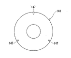
- FIG. 4 is a plan view of a low-rigidity disk used in the first embodiment;
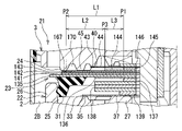
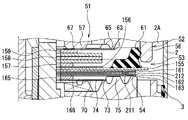
- FIG. 3 is an enlarged view showing a part of the compression side valve mechanism portion in FIG. 2 ;
- FIG. 10 is a plan view of a low-rigidity disk used in the second embodiment;
- FIG. 11 is an explanatory diagram of another form of the third embodiment; It is explanatory drawing of 4th Embodiment.
- the vertical direction in FIG. 1 will be referred to as the "vertical direction”.
- a monotube type damping force adjustable shock absorber will be described below, the first embodiment can also be applied to a double tube type damping force adjustable shock absorber provided with a reservoir.
- the damper 1 is a damping force adjustable damper in which a damping force adjusting mechanism is built in the cylinder 2.
- a piston 3 is slidably fitted in the cylinder 2 .
- the piston 3 partitions the inside of the cylinder 2 into two chambers, a cylinder upper chamber 2A and a cylinder lower chamber 2B.
- a free piston (not shown) is provided in the cylinder 2 so as to be vertically movable within the cylinder 2 .
- the free piston divides the inside of the cylinder 2 into a cylinder lower chamber 2B on the piston 3 side (upper side) and a gas chamber (not shown) on the bottom side (lower side).
- the shaft portion 6 of the piston bolt 5 is inserted through the shaft hole 4 of the piston 3 .
- the piston bolt 5 has a head portion 7 provided on the upper end portion of the shaft portion 6 and a cylindrical portion 8 formed on the outer peripheral edge portion of the head portion 7 .
- the cylindrical portion 8 is open on the upper end side and has an outer diameter larger than that of the head portion 7 .
- the piston 3 is provided with an extension-side passage 19 whose upper end opens into the cylinder upper chamber 2A, and a contraction-side passage 20 whose lower end opens into the cylinder lower chamber 2B.
- An extension-side valve mechanism 21 that controls the flow of working fluid in the extension-side passage 19 is provided on the lower end side of the piston 3 .
- a compression side valve mechanism 51 for controlling the flow of working fluid in the compression side passage 20 is provided on the upper end side of the piston 3 .
- the extension side valve mechanism 21 has a bottomed cylindrical extension side pilot case 22 (case member) attached to the shaft portion 6 of the piston bolt 5 .
- the extension-side pilot case 22 is composed of a cylindrical portion 26 and a bottom portion 27, the piston 3 side of which is open.
- the extension-side valve mechanism 21 includes a seat portion 24 formed on the outer peripheral side of the lower end surface of the piston 3 and with which the extension-side main valve 23 abuts removably; and an extension side back pressure chamber 25 formed between.
- the pressure in the extension side back pressure chamber 25 acts on the extension side main valve 23 in the valve closing direction.
- the extension-side main valve 23 is a packing valve in which an annular packing 31 made of an elastic body contacts the inner peripheral surface of the cylindrical portion 26 of the extension-side pilot case 22 over the entire circumference.
- the extension side back pressure chamber 25 communicates with the cylinder lower chamber 2B via a passage 32 formed in the bottom portion 27 of the extension side pilot case 22 and the sub-valve 30 .
- the sub-valve 30 opens when the pressure in the extension-side back pressure chamber 25 reaches a predetermined pressure, and applies resistance to the flow of working fluid from the extension-side back pressure chamber 25 to the cylinder lower chamber 2B.
- the extension-side back pressure chamber 25 communicates through a passage 32 with a first pressure receiving chamber 172 formed between the extension-side pilot case 22 and the sub-valve 30 .
- the first pressure receiving chamber 172 is defined by an endless first seat portion 173 provided on the lower end surface of the extension side pilot case 22 (the surface on the side opposite to the extension side main valve 23 side).
- a passage 32 opens inside the first seat portion 173 .
- the first pressure-receiving chambers 172 are evenly distributed in the lower end surface of the extension-side pilot case 22 at intervals in the circumferential direction.
- the extension-side pilot case 22 is provided with a back pressure introduction passage 171 through which the working fluid flows from the cylinder lower chamber 2B to the extension-side back pressure chamber 25 as the piston 3 moves in the contraction direction.
- An annular seat portion 35 is provided on the upper end surface of the extension-side pilot case 22 (the surface on the extension-side main valve 23 side).
- the seat portion 35 defines an annular pressure receiving chamber 174 provided on the outer periphery of the inner peripheral portion of the bottom portion 27 .
- the seat portion 35 has the same height in the axial direction (“vertical direction” in FIG. 2) as the upper end surface of the inner peripheral portion of the bottom portion 27 .
- a second pressure receiving chamber 177 isolated from the first pressure receiving chamber 172 is provided on the lower end face of the extension side pilot case 22 .
- a back pressure introduction passage 171 opens into the second pressure receiving chamber 177 .
- the second pressure receiving chamber 177 is defined by the second seat portion 178 .
- the second seat portion 178 extends in an arc shape between a pair of adjacent first pressure receiving chambers 172 .
- the second seat portion 178 is provided with a first orifice 175 that communicates the second pressure receiving chamber 177 and the cylinder lower chamber 2B.
- the extension-side communication passage moves the working fluid in the cylinder lower chamber 2B through the first orifice 175, the second pressure receiving chamber 177, the back pressure introduction passage 171, the pressure receiving chamber 174, and the check valve 33 by the movement of the piston 3 in the contraction direction. is introduced into the extension-side back pressure chamber 25 via .
- the disk-shaped check valve 33 that allows the flow of the working fluid from the back pressure introduction passage 171 to the extension side back pressure chamber 25 abuts on the seat portion 35 in a detachable manner.
- disks 136 are arranged in order from the main disk 135 side.
- a spacer 137, a retainer 138 constructed by stacking three discs, a spacer 139, and a check valve 33 are stacked.
- a disk 141, a disk 142, a low-rigidity disk 143, a backup disk 144 (deformation prevention portion), a spacer 145, Disk valve 40 and spacer 146 are stacked.
- the outer diameters of the discs 141 , 142 , and the low-rigidity disc 143 are the same and smaller than the outer diameter of the main disc 135 .
- the outer diameter of the backup disk 144 is smaller than the outer diameter of the low-rigidity disk 143 .
- the low-rigidity disk 143 abuts on the seat portion 24 (outer seat portion) of the piston 3 (passage forming member) in a separable and seatable manner at its outer peripheral edge.
- a seat portion 45 (inner seat portion) is provided on the inner peripheral side of the seat portion 24 of the piston 3 to receive the piston 3 side surface of the extension side main valve 23 (low-rigidity disk 143).
- At the outer peripheral edge of the low-rigidity disk 143 there are a plurality of orifices (“three” in the first embodiment) that connect the extension-side main pressure receiving chamber 170 formed inside the seat portion 24 to the cylinder lower chamber 2B.
- a notch 147 (see FIG. 4) is formed.
- the compression side valve mechanism 51 has a bottomed cylindrical compression side pilot case 52 (case member) attached to the shaft portion 6 of the piston bolt 5 .
- the compression side pilot case 52 is composed of a cylindrical portion 56 opening on the piston 3 side and a bottom portion 57.
- the compression side main valve 53 is arranged on the piston 3 side, and a compression side back pressure chamber 55 is formed inside.
- the compression-side valve mechanism 51 includes a seat portion 54 formed on the outer peripheral side of the upper end surface of the piston 3 and with which the compression-side main valve 53 abuts so as to be separable, a compression-side pilot case 52 , and a back surface of the compression-side main valve 53 . and a compression side back pressure chamber 55 formed between.
- the pressure in the compression side back pressure chamber 55 acts on the compression side main valve 53 in the valve closing direction.
- the compression side main valve 53 is a packing valve in which an annular packing 61 made of an elastic material contacts the inner peripheral surface of the cylindrical portion 56 of the compression side pilot case 52 over the entire circumference.
- the compression side back pressure chamber 55 communicates with the cylinder upper chamber 2A via a passage 62 formed in the bottom portion 57 of the compression side pilot case 52 and a sub-valve 60.
- the sub-valve 60 opens when the pressure in the compression side back pressure chamber 55 reaches a predetermined pressure, and applies resistance to the flow of working fluid from the compression side back pressure chamber 55 to the cylinder upper chamber 2A.
- the compression side back pressure chamber 55 communicates through a passage 62 with a first pressure receiving chamber 182 formed between the compression side pilot case 52 and the sub valve 60 .
- the first pressure receiving chamber 182 is defined by an endless first seat portion 183 provided on the upper end surface of the compression side pilot case 52 (the surface opposite to the compression side main valve 53 side).
- a passage 62 opens inside the first seat portion 183 .
- the first pressure receiving chambers 182 are equally arranged on the upper end surface of the contraction-side pilot case 52 at intervals in the circumferential direction.
- the compression side pilot case 52 is provided with a back pressure introduction passage 181 through which the working fluid flows from the cylinder upper chamber 2A to the compression side back pressure chamber 55 when the piston 3 moves in the extension direction.
- An annular seat portion 65 is provided on the lower end surface of the compression-side pilot case 52 (the surface on the side of the compression-side main valve 53 ).
- the seat portion 65 defines an annular pressure receiving chamber 184 provided on the outer periphery of the inner peripheral portion of the bottom portion 57 .
- the seat portion 65 has the same height in the axial direction (“vertical direction” in FIG. 2) as the lower end surface of the inner peripheral portion of the bottom portion 57 .
- a second pressure receiving chamber 187 isolated from the first pressure receiving chamber 182 is provided on the upper end face of the contraction side pilot case 52 .
- a back pressure introduction passage 181 opens into the second pressure receiving chamber 187 .
- the second pressure receiving chamber 187 is defined by the second seat portion 188 .
- the second seat portion 188 extends in an arc shape between a pair of adjacent first pressure receiving chambers 182 .
- the second seat portion 188 is provided with a first orifice 185 that communicates the second pressure receiving chamber 187 with the cylinder upper chamber 2A.
- the compression side valve mechanism 51 is formed with a compression side communication passage (communication passage) that communicates the cylinder upper chamber 2 ⁇ /b>A and the compression side back pressure chamber 55 .
- the compression-side communication passage moves the working fluid in the cylinder upper chamber 2A through the first orifice 185, the second pressure receiving chamber 187, the back pressure introduction passage 181, the pressure receiving chamber 184, and the check valve 63 by the movement of the piston 3 in the extension direction. is introduced into the contraction-side back pressure chamber 55 via .
- a disc-shaped check valve 63 that allows the flow of working fluid from the back pressure introduction passage 181 to the compression side back pressure chamber 55 abuts on the seat portion 65 in a detachable manner.
- discs 156 are arranged in order from the main disc 155 side.
- a spacer 157, a retainer 158 constructed by stacking three discs, a spacer 159, and a check valve 63 are stacked.
- a disk 161, a disk 162, a low-rigidity disk 163, a backup disk 164 (deformation prevention portion), a spacer 165, Disk valve 70 and spacer 166 are stacked.
- the outer diameters of the discs 161 , 162 , and the low-rigidity disc 163 are the same and smaller than the outer diameter of the main disc 155 .
- the outer diameter of the backup disk 164 is smaller than the outer diameter of the low-rigidity disk 163 .
- the low-rigidity disk 163 abuts on the seat portion 54 (outer seat portion) of the piston 3 at its outer peripheral edge so that it can be seated and removed.
- a seat portion 75 is provided on the inner peripheral side of the seat portion 54 of the piston 3 to receive the piston 3 side surface of the compression side main valve 53 (low-rigidity disk 163 ).
- a notch 167 (see FIG. 4) is formed.
- valve parts of the extension-side valve mechanism 21 and the contraction-side valve mechanism 51 are attached to the head 7 of the piston bolt 5 by tightening a nut 78 attached to the threaded portion (reference numerals omitted) of the shaft portion 6 of the piston bolt 5 . and washer 79 to apply an axial force.
- a common passage 11 is formed in the piston bolt 5 .
- the common passage 11 has an axial passage 12 formed inside (axial hole) of the sleeve 15 .
- the upper end of the sleeve 15 is fitted into a hole 16 that opens into the head 6 of the piston bolt 5 .
- the common passage 11 has an axial passage 13 formed in the lower portion of the hole 16 (the portion below the lower end of the sleeve 15).
- the common passage 11 has an axial passage 14 which is a small diameter hole whose upper end opens into a hole 16 .
- the inner diameter of the common passage 11 is the largest in the axial passage 13 and decreases in the order of the axial passage 12 and the axial passage 14 .
- the axial passage 12 opens at the end surface 9 of the head 7 of the piston bolt 5 .
- the lower end of the piston rod 10 is connected to the upper end of the solenoid case 94 by screw connection.
- the upper end side of the piston rod 10 extends outside the cylinder 2 .
- a locking nut 47 is attached to the lower end (threaded portion) of the piston rod 10 .
- a small diameter portion 18 is formed at the lower end of the piston rod 10 (below the threaded portion).
- a seat member 48 that seals between the solenoid case 94 and the piston rod 10 is mounted in an annular groove (reference numerals omitted) formed in the outer peripheral surface of the small diameter portion 18 .
- the extension-side back pressure chamber 25 passes through an orifice 37 provided in the inner periphery of the check valve 33 and an annular passage 38 formed in the inner periphery of the bottom portion 27 of the extension-side pilot case 22 . It communicates with a radial passage 34 formed in 6 .
- the radial passage 34 communicates with the axial passage 14 .
- the axial passage 14 communicates with a radial passage 39 formed in the shaft portion 6 of the piston bolt 5 .
- the radial passage 39 includes an annular passage 41 formed in the lower end portion of the shaft hole 4 of the piston 3, a plurality of notches 42 formed in the inner peripheral portion 17 of the piston 3, and a disc valve provided in the piston 3. It communicates with the extension side passage 19 via 40 .
- the disk valve 40 abuts on an annular seat portion 43 of the piston 3 provided on the inner peripheral side of the opening of the seat portion 24 and the extension side passage 19 so as to be separable and seatable.
- the disk valve 40 is a check valve that allows the working fluid to flow from the radial passage 39 to the extension passage 19 .
- the compression side back pressure chamber 55 includes an orifice 67 provided on the inner periphery of the check valve 63, a width across flat portion 77 formed on the shaft portion 6 of the piston bolt 5, and an inner periphery of the bottom portion 57 of the compression side pilot case 52. It communicates with a radial passage 64 formed in the shaft portion 6 of the piston bolt 5 via an annular passage 68 formed in the portion. The radial passage 64 communicates with the axial passage 12 through a hole 66 formed in the side wall of the sleeve 15 .
- the radial passage 64 includes a width across flat portion 77, an annular passage 71 formed in the upper end portion of the axial hole 4 of the piston 3, a plurality of notches 72 formed in the inner peripheral portion 17 of the piston 3, and a is communicated with the compression side passage 20 via a disk valve 70 provided in the .
- the disk valve 70 abuts on an annular seat portion 73 of the piston 3 provided on the inner peripheral side of the opening of the seat portion 54 and the compression side passage 20 so as to be separable and seatable.
- the disk valve 70 is a check valve that allows working fluid to flow from the radial passage 64 to the compression side passage 20 .
- the flow of working fluid in the common passage 11 is controlled by a pilot valve 81 (pilot control valve).
- the pilot valve 81 has a valve spool 82 slidably provided in the common passage 11 and a seat portion 83 formed around the opening periphery of the axial passage 14 at the bottom of the hole 16 .
- the valve spool 82 consists of a solid shaft, and connects a sliding portion 84 inserted into the sleeve 15, a valve body 85 that abuts on the seat portion 83 so as to be separable and seatable, and the sliding portion 84 and the valve body 85. and a connecting portion 86 .
- a head portion 87 of the valve spool 82 is formed at the upper end of the sliding portion 84 .
- An outer flange-shaped spring receiving portion 88 is formed at the lower end of the head portion 87 .
- An inner peripheral portion of a spring disk 113 that biases the valve body 85 in the valve opening direction is connected to the spring receiving portion 88 .
- the head 87 of the valve spool 82 abuts (is pressed against) the lower end surface 93 of the operating rod 92 of the solenoid 91 .
- a first chamber 130 is formed around the head 7 of the valve spool 82 .
- a bottomed cylindrical cap 121 with an open upper end is attached to the outer peripheral surface 36 of the head 7 of the piston bolt 5 .
- a bottom portion 122 of the cap 121 is provided with an insertion hole 123 through which the shaft portion 6 of the piston bolt 5 is inserted.
- a plurality of notches 124 (indicated as “two” in FIG. 5) are provided on the outer circumference of the insertion hole 123 .
- the notch 124 communicates with the width across flats portion 77 formed in the shaft portion 6 .
- An annular groove 127 is provided on the outer peripheral surface 36 of the head 7 of the piston bolt 5 .
- a seal member 128 is provided in the annular groove 127 to seal between the head portion 7 of the piston bolt 5 and the cylindrical portion 125 of the cap 121 .
- An annular second chamber 131 is formed between the head 7 of the piston bolt 5 and the cap 121 .
- a spool back pressure relief valve 107 Between the head portion 7 of the piston bolt 5 and the bottom portion 122 of the cap 121, a spool back pressure relief valve 107, a spacer 108, and a retainer 132 are provided in this order from the head portion 7 side. Spool back pressure relief valve 107 , spacer 108 and retainer 132 are provided within second chamber 131 .
- the spool back pressure relief valve 107 is a check valve that allows working fluid to flow from the first chamber 130 to the second chamber 131 through the passage 105 formed in the head 7 .
- An outer peripheral edge portion of the spool back pressure relief valve 107 abuts on an annular seat portion 109 formed on the lower end surface of the head portion 7 of the piston bolt 5 so as to be separable and seatable.
- the inner peripheral edge of the retainer 132 is provided with a plurality of cutouts 133 that allow the second chamber 131 to communicate with the width across flats portion 77 and the cutouts 124 of the cap 121 .
- a retainer 59 is interposed between the bottom portion 122 of the cap 121 and the sub-valve 60 to determine the maximum opening amount of the sub-valve 60 .
- a fail-safe valve 111 is configured in the first chamber 130 .
- the fail-safe valve 111 has a disc 112 (valve seat) against which the spring receiving portion 88 (valve element) of the head portion 87 of the valve spool 82 can be seated and detached.
- the outer peripheral edges of the disc 112 and the spring disc 113 are held between the head 7 of the piston bolt 5 and the core 99 of the solenoid 91 .
- the fail state when the thrust of the solenoid 91 is 0
- the biasing force of the spring disc 113 causes the spring receiving portion 88 to contact (press) the disc 112, thereby closing the fail-safe valve 111.
- the solenoid 91 has an actuation rod 92, a solenoid case 94, and a coil 95.
- a plunger 96 is coupled to the outer circumference of the operating rod 92 .
- the plunger 96 generates thrust by energizing the coil 95 .
- An intra-rod passage 97 is formed inside the operating rod 92 .
- the operating rod 92 is guided vertically (axially) by a bush 100 provided on the core 98 .
- annular groove 115 is provided on the outer peripheral surface of the core 99 .
- a seal member 116 for sealing between the lower end of the solenoid case 94 and the core 99 is mounted in the annular groove 115 .
- annular passage 117 is formed between the piston bolt 5 , the solenoid case 94 and the core 99 .
- the annular passage 117 communicates with the cylinder upper chamber 2 ⁇ /b>A via a passage 118 provided at the lower end of the cylindrical portion 8 of the piston bolt 5 .
- a spool back pressure chamber 101 is formed inside the core 99 of the solenoid 91 .
- the spool back pressure chamber 101 communicates with the rod back pressure chamber 103 via the notch 102 of the operating rod 92 and the intra-rod passage 97 .
- the valve spool 82 is urged by the urging force of the spring disc 113 in the valve opening direction ("upward direction” in FIG. 4) of the pilot valve 81 (valve element 85), thereby Portion 88 abuts disk 112 .
- communication between the spool back pressure chamber 101 and the first chamber 130 is cut off.
- the valve spool 82 When the coil 95 is energized, the valve spool 82 is urged by the thrust generated by the plunger 96 in the valve closing direction ("downward direction" in FIG. 2) of the pilot valve 81 (valve element 85). As a result, the valve spool 82 moves against the biasing force of the spring disk 113 and the valve body 85 is seated on the seat portion 83 .
- the opening pressure of the pilot valve 81 can be adjusted by controlling the energization of the coil 95 . In the soft mode in which the current value of energization of the coil 95 is small, the biasing force of the spring disk 113 and the thrust generated by the plunger 96 are balanced, and the valve body 85 is separated from the seat portion 83 by a certain distance. .
- Extension stroke During the extension stroke, the working fluid in the cylinder upper chamber 2A flows through the upstream back pressure introduction passage, that is, the extension side passage 19, the orifice 44 formed in the disk valve 40, the notch 42 formed in the piston 3, and the piston 3.
- the upstream back pressure introduction passage that is, the extension side passage 19, the orifice 44 formed in the disk valve 40, the notch 42 formed in the piston 3, and the piston 3.
- an annular passage 41 formed in the shaft hole 4 a radial passage 39 , an axial passage 14 , a radial passage 34 , an annular passage 38 formed in the extension side pilot case 22 , and an orifice 37 formed in the check valve 33 .
- the working fluid in the cylinder upper chamber 2A passes through the compression side communication passage, that is, the first orifice 185, the second pressure receiving chamber 187, the back pressure introducing passage 181, and the check valve 63. , is introduced into the compression side back pressure chamber 55 .
- the compression side communication passage that is, the first orifice 185, the second pressure receiving chamber 187, the back pressure introducing passage 181, and the check valve 63.
- the working fluid introduced into the compression-side back pressure chamber 55 during the extension stroke passes through the orifice 67 formed in the check valve 63, the width across flat portion 77 formed in the shaft portion 6 of the piston bolt 5, and the compression-side pilot case. 52, a notch 72 formed in the inner peripheral portion 17 of the piston 3, a disk valve 70, and a compression side passage 20, to the cylinder lower chamber 2B (downstream chamber). ), the orifice characteristic of the orifice 67 and the valve characteristic damping force of the disk 70 are obtained before the expansion main valve 23 opens, ie, in the low piston speed region.
- the low-rigidity disk 163 seated on the seat portion 54 (outer seat portion) and the low-rigidity disk 163 Hydraulic oil in the cylinder upper chamber 2A may enter between the low-rigidity disk 163 and the disk 162 adjacent to the low-rigidity disk 163 .
- the fulcrum on the inner peripheral side of the low-rigidity disk 163 is P1 (the outer periphery of the spacer 165). end) to the outer peripheral side (left side in FIG. 3) P3 (outer peripheral end of the backup disk 164), in other words, the moment length (distance between fulcrums) of the low-rigidity disk 163 is changed from L1 to L2 by L3 , and the bending rigidity of the low-rigidity disk 163 can be increased.
- the working fluid in the cylinder lower chamber 2B (upstream side chamber) flows through the extension side communication passage, that is, the first orifice 175, the second pressure receiving chamber 177, the back pressure introduction passage 171 (downstream side back pressure introduction passage). passage) and a check valve 33 into the extension side back pressure chamber 25 .
- the extension side communication passage that is, the first orifice 175, the second pressure receiving chamber 177, the back pressure introduction passage 171 (downstream side back pressure introduction passage). passage
- a check valve 33 into the extension side back pressure chamber 25 .
- the working fluid introduced into the extension-side back pressure chamber 25 during the compression stroke passes through an orifice 37 formed in the check valve 33, an annular passage 38 formed in the inner peripheral portion of the bottom portion 27 of the extension-side pilot case 22, a diameter A directional passage 34, an axial passage 14, a radial passage 39, an annular passage 41 formed in the shaft hole 4 of the piston 3, a notch 42 formed in the inner peripheral portion 17 of the piston 3, a disk valve 40, and an extension side passage.
- 19 to the cylinder upper chamber 2A (downstream side chamber) the orifice characteristics due to the orifice 37 and the valve characteristics due to the disk 40 are attenuated before the compression side main valve 53 opens, that is, in the low piston speed region. gain power.
- the fulcrum on the inner peripheral side of the low-rigidity disk 143 is P1 (the outer periphery of the spacer 145). end) to the outer peripheral side (the right side in FIG. 3) P3 (the outer peripheral end of the backup disk 144), in other words, the moment length (distance between fulcrums) of the low-rigidity disk 143 is changed from L1 to L2 by L3 , and the bending rigidity of the low-rigidity disk 143 can be increased.
- the inner peripheral portion of the low-rigidity disk 163 is supported by the backup disc 164 (deformation prevention portion), so that the fulcrum on the inner peripheral side of the low-rigidity disk 163 is It was moved from P1 (the outer peripheral end of the spacer 165) to P3 (the outer peripheral end of the backup disk 164) on the outer peripheral side.
- the moment length (distance between fulcrums) of the low-rigidity disk 163 is calculated from the difference between the radius of the low-rigidity disk 163 and the radius of the spacer 165 ("L1" in FIG. 5). It is shortened to the difference from the radius of disk 164 ("L2" in FIG. 5), and the bending rigidity of low-rigidity disk 163 is improved.
- the backup disc 164 does not prevent the valve opening of the low-rigidity disc 163, so that a damping force with low valve characteristics can be obtained as in the conventional art.
- the same designations and reference numerals are used for common parts with the first embodiment, and redundant explanations are omitted.
- the extension side main valve 23 and the compression side main valve 53 have the same basic structure. Therefore, the relevant part of the compression side main valve 53 will be explained, and the explanation of the relevant part of the expansion side main valve 23 will be omitted.
- the inner peripheral portion of the low-rigidity disk 163 is supported by the backup disk 164 (deformation prevention portion), and the pressure in the cylinder upper chamber 2A increases during the extension stroke, thereby causing the low-rigidity disk 163 and the adjacent disk 162 to move. It is constructed so as to prevent deformation of the low-rigidity disk 163 due to the hydraulic oil flowing in between.
- one side of the low-rigidity disk 163 (the side of the compression-side back pressure chamber 55) and the other side (the side of the compression-side back pressure chamber 55) are attached to the low-rigidity disk 163 without using the backup disk 164 (see FIG. 5).
- a plurality of (“three” in the second embodiment) holes 191 are formed to constantly communicate with the piston 3 side).
- the hole 191 is an elongated hole provided on the inner peripheral side of the seat portion 75 (inner seat portion) and extending in the circumferential direction between adjacent cutouts 167 .
- the hydraulic fluid that flows between the low-rigidity disk 163 and the adjacent disk 162, that is, the hydraulic fluid that flows into one side of the low-rigidity disk 163 The oil can escape to the other side of the low-rigidity disk 163, and the stress acting on the low-rigidity disk 163 is reduced, thereby preventing deformation of the low-rigidity disk 163.
- the hydraulic fluid (pressure) released to the other side of the low-rigidity disk 163 flows (propagates) through the compression-side passage 20 to the cylinder lower chamber 2B.
- the same designations and reference numerals are used for common parts with the first embodiment, and redundant explanations are omitted.
- the extension side main valve 23 and the compression side main valve 53 have the same basic structure. Therefore, the relevant part of the compression side main valve 53 will be explained, and the explanation of the relevant part of the expansion side main valve 23 will be omitted.
- the backup disk 164 (see FIG. 5) that supports the low-rigidity disk 163 is not used in the third embodiment.
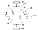
- a check valve 201 (deformation preventing portion) is provided between the low-rigidity disk 165 and the piston 3 (passage forming member).
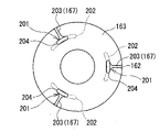
- the check valve 201 includes a plurality of ("three" in the third embodiment) elongated holes formed in the disc 162 adjacent to each notch 167 of the low-rigidity disc 163. 202. Each long hole 202 is evenly distributed on the same circle with a radius smaller than the radius of the seat portion 75 (inner seat portion).
- the check valve 201 is formed in the low-rigidity disk 163 and extends through each notch 167 in the radial direction of the low-rigidity disk 163 toward the shaft hole 168 to reach the corresponding long hole 202 of the adjacent disk 162 . It has a plurality of (“three” in the third embodiment) radial notches 203 . Further, the check valve 201 has a plurality of (“three” in the third embodiment) circumferential notches 204 provided for each radial notch 203 and extending in the circumferential direction.
- the radial cutouts 203 and the circumferential cutouts 204 form a substantially T-shape, and each circumferential cutout 204 is arranged to open (oppose) the corresponding long hole 202 .
- the circumferential length of the circumferential notch 204 is shorter than the circumferential length of the long hole 202 .
- a check valve 201 is configured to release to the other side of the low-rigidity disk 163 .
- the pressure in the cylinder upper chamber 2A increases during the extension stroke, and the hydraulic oil that has flowed between the low-rigidity disk 163 and the adjacent disk 162 flows through the long hole 202 of the disk 162 and into the low-rigidity disk 163. Since the hydraulic oil can escape to the cylinder lower chamber 2B via the circumferential notch 204 and the compression side passage 20, deformation of the low-rigidity disc 163 due to the flow of hydraulic oil between the discs 162 and 163 can be prevented. It is possible, and damage to the low-rigidity disk 163 can be suppressed.
- two elongated holes 202 are formed in the disk 162 for one circumferential notch 204 of the low-rigidity disk 163, and the circumferential notch 204
- the check valves 201 may be configured by opening the ends on both sides in the circumferential direction to the respective ends of the adjacent elongated holes 202 .
- the same designations and reference numerals are used for common parts with the first embodiment, and redundant explanations are omitted.
- the extension side main valve 23 and the compression side main valve 53 have the same basic structure. Therefore, the relevant part of the compression side main valve 53 will be explained, and the explanation of the relevant part of the expansion side main valve 23 will be omitted.
- the backup disk 164 (see FIG. 5) that supports the low-rigidity disk 163 is not used.
- an intermediate protruding portion 211 (deformation prevention portion) is formed between the disk 162 adjacent to the low-rigidity disk 163 and the disk 161 adjacent to the main disk 155.
- a disc 212 was interposed. The outer diameter of disk 212 is the same as the outer diameter of disks 161-163.
- the intermediate projecting portion 211 is positioned between the seat portion 54 (outer seat portion) and the seat portion 75 (inner seat portion) formed in the piston 3 (passage forming member) in a state of being assembled to the compression side valve mechanism 51 . placed in The intermediate projecting portion 211 projects toward the low-rigidity disk 163 with respect to the lower surface 213 of the disk 212 and presses the outer peripheral edge of the disk 162 against the low-rigidity disk 163 to bring them into close contact.
- the intermediate protrusion 211 is press molded into the metal disc 212 and extends along the outer periphery of the disc 212 .
- the intermediate protruding portion 211 is formed in a circular (endless) shape, but it may be configured by equidistantly distributing a plurality of protruding portions (islands) extending in the circumferential direction, or equally distributing projections on the same circle ( arranged at regular intervals).
- the intermediate protruding portion 211 formed on the disk 212 presses the outer peripheral edge of the disk 162 adjacent to the low-rigidity disk 163 to bring them into close contact with each other, so that the pressure in the cylinder upper chamber 2A increases during the extension stroke. Hydraulic oil does not flow between the low-rigidity disk 163 and the adjacent disk 162 even if there is. As a result, it is possible to prevent deformation of the low-rigidity disk 163 due to the hydraulic oil flowing between the disks 162 and 163, and damage to the low-rigidity disk 163 can be suppressed.
- the embodiment is not limited to the form described above, and can be configured as follows, for example.
- the pilot cases 22, 52 (case members) in which the back pressure chambers 25, 55 are formed are fixed to the piston bolt 5.
- the main valve is opened.
- the present invention can also be applied to a so-called conventional shock absorber that does not have a valve mechanism in which a case member having a back pressure chamber moves when valved, that is, does not have an actuator (solenoid).
- a so-called piston built-in type damping force adjustable shock absorber in which a damping force generating mechanism having an actuator (solenoid) is built in the cylinder 2, has been exemplified and explained.
- the present embodiment can be applied to a so-called control valve laterally attached damping force adjustable hydraulic shock absorber in which the damping force generating mechanism is laterally attached to the side wall of the outer cylinder (cylinder).
- the present invention is not limited to the above-described embodiments, and includes various modifications.
- the above-described embodiments have been described in detail in order to explain the present invention in an easy-to-understand manner, and are not necessarily limited to those having all the configurations described.
- part of the configuration of one embodiment can be replaced with the configuration of another embodiment, and the configuration of another embodiment can be added to the configuration of one embodiment.
- 1 shock absorber 2 cylinder, 3 piston (passage forming member), 10 piston rod, 19 extension side passage, 20 compression side passage, 22 extension side pilot case (case member), 23 extension side main valve, 24 seat portion (outside seat portion), 25 extension side back pressure chamber, 45 seat portion (inner seat portion), 52 compression side pilot case (case member), 53 compression side main valve, 54 seat portion (outer seat portion), 55 compression side back pressure Chamber, 75 seat portion (inner seat portion), 143 low-rigidity disk, 144 backup disk (deformation prevention portion), 163 low-rigidity disk, 164 backup disk (deformation prevention portion)
Landscapes
- Engineering & Computer Science (AREA)
- General Engineering & Computer Science (AREA)
- Mechanical Engineering (AREA)
- Fluid-Damping Devices (AREA)
Priority Applications (5)
| Application Number | Priority Date | Filing Date | Title |
|---|---|---|---|
| US18/273,586 US20240077126A1 (en) | 2021-02-04 | 2022-02-01 | Shock absorber |
| JP2022579546A JP7507262B2 (ja) | 2021-02-04 | 2022-02-01 | 緩衝器 |
| CN202280013330.7A CN116848336A (zh) | 2021-02-04 | 2022-02-01 | 缓冲器 |
| DE112022000968.3T DE112022000968T5 (de) | 2021-02-04 | 2022-02-01 | Stossdämpfer |
| KR1020237016036A KR102858543B1 (ko) | 2021-02-04 | 2022-02-01 | 완충기 |
Applications Claiming Priority (2)
| Application Number | Priority Date | Filing Date | Title |
|---|---|---|---|
| JP2021016764 | 2021-02-04 | ||
| JP2021-016764 | 2021-02-04 |
Publications (1)
| Publication Number | Publication Date |
|---|---|
| WO2022168817A1 true WO2022168817A1 (ja) | 2022-08-11 |
Family
ID=82741350
Family Applications (1)
| Application Number | Title | Priority Date | Filing Date |
|---|---|---|---|
| PCT/JP2022/003732 Ceased WO2022168817A1 (ja) | 2021-02-04 | 2022-02-01 | 緩衝器 |
Country Status (6)
| Country | Link |
|---|---|
| US (1) | US20240077126A1 (https=) |
| JP (1) | JP7507262B2 (https=) |
| KR (1) | KR102858543B1 (https=) |
| CN (1) | CN116848336A (https=) |
| DE (1) | DE112022000968T5 (https=) |
| WO (1) | WO2022168817A1 (https=) |
Cited By (1)
| Publication number | Priority date | Publication date | Assignee | Title |
|---|---|---|---|---|
| US12618448B2 (en) | 2023-05-08 | 2026-05-05 | Advanced Suspension Technology Llc | Piston for shock absorber with optimized bleed range and tuneability |
Families Citing this family (1)
| Publication number | Priority date | Publication date | Assignee | Title |
|---|---|---|---|---|
| CN118162897A (zh) * | 2024-03-29 | 2024-06-11 | 蓝讯汽车空气悬架系统(滁州)有限公司 | 阻尼阀装置及其装配方法、减震器 |
Citations (7)
| Publication number | Priority date | Publication date | Assignee | Title |
|---|---|---|---|---|
| JPH0571486U (ja) * | 1991-02-28 | 1993-09-28 | カヤバ工業株式会社 | 減衰力調整装置 |
| JPH084818A (ja) * | 1994-06-15 | 1996-01-12 | Tokico Ltd | 減衰力調整式油圧緩衝器 |
| JP2016089898A (ja) * | 2014-10-31 | 2016-05-23 | 日立オートモティブシステムズ株式会社 | 流体圧緩衝器 |
| WO2017038571A1 (ja) * | 2015-08-31 | 2017-03-09 | 日立オートモティブシステムズ株式会社 | 緩衝器 |
| WO2017145983A1 (ja) * | 2016-02-24 | 2017-08-31 | 日立オートモティブシステムズ株式会社 | 減衰力調整式緩衝器 |
| JP2019163768A (ja) * | 2016-07-26 | 2019-09-26 | 日立オートモティブシステムズ株式会社 | 緩衝器 |
| JP2020016288A (ja) * | 2018-07-25 | 2020-01-30 | 日立オートモティブシステムズ株式会社 | 緩衝器 |
Family Cites Families (11)
| Publication number | Priority date | Publication date | Assignee | Title |
|---|---|---|---|---|
| JP2008089037A (ja) | 2006-09-29 | 2008-04-17 | Hitachi Ltd | 減衰力調整式油圧緩衝器 |
| JP5843842B2 (ja) * | 2013-05-30 | 2016-01-13 | 日立オートモティブシステムズ株式会社 | 減衰力調整式緩衝器 |
| KR102139846B1 (ko) * | 2013-11-29 | 2020-07-30 | 히다치 오토모티브 시스템즈 가부시키가이샤 | 완충기 |
| JP6188598B2 (ja) * | 2014-01-31 | 2017-08-30 | 日立オートモティブシステムズ株式会社 | シリンダ装置 |
| JP6351443B2 (ja) * | 2014-08-29 | 2018-07-04 | 日立オートモティブシステムズ株式会社 | 緩衝器 |
| US11078982B2 (en) * | 2017-03-10 | 2021-08-03 | Hitachi Astemo, Ltd. | Damper |
| WO2019049844A1 (ja) * | 2017-09-05 | 2019-03-14 | 日立オートモティブシステムズ株式会社 | 緩衝器 |
| CN113195934A (zh) * | 2018-12-25 | 2021-07-30 | 日立安斯泰莫株式会社 | 缓冲器 |
| JP7069353B2 (ja) * | 2019-01-18 | 2022-05-17 | 日立Astemo株式会社 | 緩衝器 |
| JP6806982B1 (ja) | 2019-07-22 | 2021-01-06 | 東田商工株式会社 | 屋内空間部の吊り張り体、及び該屋内空間部の吊り張り体を用い間仕切り方法 |
| WO2022075011A1 (ja) * | 2020-10-08 | 2022-04-14 | 日立Astemo株式会社 | 緩衝器 |
-
2022
- 2022-02-01 KR KR1020237016036A patent/KR102858543B1/ko active Active
- 2022-02-01 US US18/273,586 patent/US20240077126A1/en active Pending
- 2022-02-01 WO PCT/JP2022/003732 patent/WO2022168817A1/ja not_active Ceased
- 2022-02-01 DE DE112022000968.3T patent/DE112022000968T5/de active Pending
- 2022-02-01 CN CN202280013330.7A patent/CN116848336A/zh active Pending
- 2022-02-01 JP JP2022579546A patent/JP7507262B2/ja active Active
Patent Citations (7)
| Publication number | Priority date | Publication date | Assignee | Title |
|---|---|---|---|---|
| JPH0571486U (ja) * | 1991-02-28 | 1993-09-28 | カヤバ工業株式会社 | 減衰力調整装置 |
| JPH084818A (ja) * | 1994-06-15 | 1996-01-12 | Tokico Ltd | 減衰力調整式油圧緩衝器 |
| JP2016089898A (ja) * | 2014-10-31 | 2016-05-23 | 日立オートモティブシステムズ株式会社 | 流体圧緩衝器 |
| WO2017038571A1 (ja) * | 2015-08-31 | 2017-03-09 | 日立オートモティブシステムズ株式会社 | 緩衝器 |
| WO2017145983A1 (ja) * | 2016-02-24 | 2017-08-31 | 日立オートモティブシステムズ株式会社 | 減衰力調整式緩衝器 |
| JP2019163768A (ja) * | 2016-07-26 | 2019-09-26 | 日立オートモティブシステムズ株式会社 | 緩衝器 |
| JP2020016288A (ja) * | 2018-07-25 | 2020-01-30 | 日立オートモティブシステムズ株式会社 | 緩衝器 |
Cited By (1)
| Publication number | Priority date | Publication date | Assignee | Title |
|---|---|---|---|---|
| US12618448B2 (en) | 2023-05-08 | 2026-05-05 | Advanced Suspension Technology Llc | Piston for shock absorber with optimized bleed range and tuneability |
Also Published As
| Publication number | Publication date |
|---|---|
| KR20230084572A (ko) | 2023-06-13 |
| JP7507262B2 (ja) | 2024-06-27 |
| DE112022000968T5 (de) | 2023-11-23 |
| JPWO2022168817A1 (https=) | 2022-08-11 |
| CN116848336A (zh) | 2023-10-03 |
| KR102858543B1 (ko) | 2025-09-10 |
| US20240077126A1 (en) | 2024-03-07 |
Similar Documents
| Publication | Publication Date | Title |
|---|---|---|
| JP5952760B2 (ja) | 減衰弁 | |
| JP6808837B2 (ja) | 緩衝器 | |
| JP7182656B2 (ja) | 緩衝器に用いられる機構 | |
| CN111630295B (zh) | 阻尼阀和缓冲器 | |
| KR102223705B1 (ko) | 완충기 | |
| JPH1073141A (ja) | 減衰力調整式油圧緩衝器 | |
| JP6516916B2 (ja) | 減衰力調整式緩衝器 | |
| JP7485579B2 (ja) | 減衰バルブおよび緩衝器 | |
| JP7069353B2 (ja) | 緩衝器 | |
| JP7296268B2 (ja) | 減衰力調整式緩衝器 | |
| WO2022168817A1 (ja) | 緩衝器 | |
| JP7171495B2 (ja) | 緩衝器 | |
| JP7422245B2 (ja) | 緩衝器 | |
| JP7710032B2 (ja) | 緩衝器 | |
| JP7422037B2 (ja) | 緩衝器 | |
| WO2025258135A1 (ja) | 緩衝器 | |
| WO2022209576A1 (ja) | 緩衝器及びバルブ装置 |
Legal Events
| Date | Code | Title | Description |
|---|---|---|---|
| 121 | Ep: the epo has been informed by wipo that ep was designated in this application |
Ref document number: 22749689 Country of ref document: EP Kind code of ref document: A1 |
|
| ENP | Entry into the national phase |
Ref document number: 2022579546 Country of ref document: JP Kind code of ref document: A |
|
| ENP | Entry into the national phase |
Ref document number: 20237016036 Country of ref document: KR Kind code of ref document: A |
|
| WWE | Wipo information: entry into national phase |
Ref document number: 18273586 Country of ref document: US |
|
| WWE | Wipo information: entry into national phase |
Ref document number: 202280013330.7 Country of ref document: CN |
|
| WWE | Wipo information: entry into national phase |
Ref document number: 112022000968 Country of ref document: DE |
|
| 122 | Ep: pct application non-entry in european phase |
Ref document number: 22749689 Country of ref document: EP Kind code of ref document: A1 |