WO2022168532A1 - 吸収体、及び、吸収体の製造方法 - Google Patents
吸収体、及び、吸収体の製造方法 Download PDFInfo
- Publication number
- WO2022168532A1 WO2022168532A1 PCT/JP2022/000494 JP2022000494W WO2022168532A1 WO 2022168532 A1 WO2022168532 A1 WO 2022168532A1 JP 2022000494 W JP2022000494 W JP 2022000494W WO 2022168532 A1 WO2022168532 A1 WO 2022168532A1
- Authority
- WO
- WIPO (PCT)
- Prior art keywords
- absorbent
- absorbent body
- core
- core wrap
- liquid
- Prior art date
- Legal status (The legal status is an assumption and is not a legal conclusion. Google has not performed a legal analysis and makes no representation as to the accuracy of the status listed.)
- Ceased
Links
Images

Classifications
-
- A—HUMAN NECESSITIES
- A61—MEDICAL OR VETERINARY SCIENCE; HYGIENE
- A61F—FILTERS IMPLANTABLE INTO BLOOD VESSELS; PROSTHESES; DEVICES PROVIDING PATENCY TO, OR PREVENTING COLLAPSING OF, TUBULAR STRUCTURES OF THE BODY, e.g. STENTS; ORTHOPAEDIC, NURSING OR CONTRACEPTIVE DEVICES; FOMENTATION; TREATMENT OR PROTECTION OF EYES OR EARS; BANDAGES, DRESSINGS OR ABSORBENT PADS; FIRST-AID KITS
- A61F13/00—Bandages or dressings; Absorbent pads
- A61F13/15—Absorbent pads, e.g. sanitary towels, swabs or tampons for external or internal application to the body; Supporting or fastening means therefor; Tampon applicators
- A61F13/53—Absorbent pads, e.g. sanitary towels, swabs or tampons for external or internal application to the body; Supporting or fastening means therefor; Tampon applicators characterised by the absorbing medium
- A61F13/531—Absorbent pads, e.g. sanitary towels, swabs or tampons for external or internal application to the body; Supporting or fastening means therefor; Tampon applicators characterised by the absorbing medium having a homogeneous composition through the thickness of the pad
- A61F13/532—Absorbent pads, e.g. sanitary towels, swabs or tampons for external or internal application to the body; Supporting or fastening means therefor; Tampon applicators characterised by the absorbing medium having a homogeneous composition through the thickness of the pad inhomogeneous in the plane of the pad
Definitions
- the present invention relates to an absorbent body and a method for manufacturing the absorbent body.
- Patent Document 1 discloses an absorbent body having an absorbent core in which an absorbent polymer is contained in an assembly of liquid-absorbent fibers, and a core wrap sheet covering the upper and lower surfaces of the absorbent core. .
- the absorbent core is stretched in the plane direction. It claims to evenly distribute the absorbent polymer.
- the absorbent core is divided into a plurality of regions (30 mm ⁇ 30 mm square regions) in the longitudinal direction and the width direction of the absorbent body, and the content of the absorbent polymer is measured for each divided region
- the ratio (row standard deviation / row average) indicating the variation in the content of the absorbent polymer is 0.20 or less. I have to.
- Patent Literature 1 out of the divided areas of the absorbent core, those areas that do not overlap with the absorbent core are excluded from measurement. Therefore, the side portions of the hourglass-shaped absorbent core in the width direction are not included in the measurement of the content of the absorbent polymer, and variations in the polymer on the side portions of the absorbent core are not taken into consideration. If the absorption performance of the side portions of the absorbent core is lowered without considering the absorption performance of the side portions of the absorbent core in this way, it will lead to lateral leakage of the excreted liquid.
- the present invention has been made in view of the conventional problems as described above, and its object is to prevent the superabsorbent polymer and liquid-absorbent fibers from falling off from the sides of the absorbent body in the lateral direction, thereby Maintaining the absorbent performance of the sides of the body.
- the main invention for achieving the above object has a longitudinal direction, a lateral direction, and a thickness direction, and has an absorbent core and core wrap sheets arranged on both sides of the absorbent core in the thickness direction.
- An absorbent body wherein the absorbent core comprises liquid-absorbing fibers and a superabsorbent polymer, and at least a pair of lateral sides of the absorbent body are compressed in the thickness direction It has a compressed portion, and in the compressed portion of the side portion of the absorbent body, the portion in which the liquid-absorbent fiber and the superabsorbent polymer are arranged is divided into six in the longitudinal direction, and the lateral A region divided into two in the direction is defined as a divided region, and for each divided region, the area occupied by the liquid-absorbent fiber and the superabsorbent polymer when the divided region is viewed in plan in the thickness direction is defined as the divided region.
- the absorbent body is characterized in that, when the area ratio is calculated by dividing by the area of , the CV
- the present invention it is possible to prevent the super-absorbent polymer and the liquid-absorbing fibers from falling off from the side portions of the absorbent body in the horizontal direction, thereby maintaining the absorption performance of the side portions of the absorbent body.
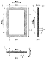
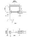
- FIG. 1A is a plan view of the absorbent body 1 viewed in the thickness direction
- FIG. 1B is a side view of the absorbent body 1 viewed in the horizontal direction
- FIG. 1C is a front view of the absorbent body 1 viewed in the vertical direction.
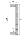
- 4 is an explanatory diagram of divided regions r1 to r12 of the pressing unit 4.
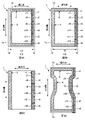
- FIG. 3A to 3D are diagrams showing modifications of the absorbent body 1.
- FIG. 4A to 4E are explanatory diagrams of a method for measuring the occupied area ratio of the absorbent core 10.
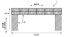
- FIG. 4 is an explanatory view of second divided regions r1' to r12' of the compressed portion 4 at the longitudinal end portion of the absorbent body 1.
- FIG. 6A and 6B are explanatory diagrams of a dropping test of the superabsorbent polymer 12 from the absorbent body 1.
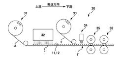
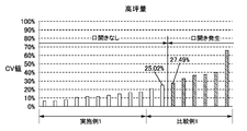
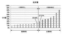
- FIG. FIG. 4 is an explanatory diagram of a method for manufacturing the absorbent body 1; 4 is a graph showing measurement results of Example 1 and Comparative Example 1 (high basis weight absorbent). 4 is a graph showing the measurement results of Example 2 and Comparative Example 2 (low basis weight absorbent).
- An absorbent body having a vertical direction, a horizontal direction, and a thickness direction, and having an absorbent core and core wrap sheets arranged on both sides of the absorbent core in the thickness direction, wherein the absorbent core is , a liquid-absorbent fiber, and a superabsorbent polymer, wherein the absorbent body has a pressed portion in which at least a pair of side portions in the lateral direction are pressed in the thickness direction, and the absorbent body has the Of the compressed portion of the side portion, the portion where the liquid-absorbent fiber and the superabsorbent polymer are arranged is divided into 6 regions in the longitudinal direction and divided into 2 regions in the horizontal direction as divided regions, When the area ratio is calculated by dividing the area occupied by the liquid-absorbent fiber and the superabsorbent polymer when the divided region is viewed in plan in the thickness direction for each divided region by the area of the divided region. , an absorbent body
- the compressed portions are provided at a pair of ends of the absorbent body in the longitudinal direction, and among the compressed portions at the ends of the absorbent body, the liquid-absorbing fibers and the
- the portion where the superabsorbent polymer is arranged is divided into six in the horizontal direction and two regions in the vertical direction are defined as second divided regions, and each of the second divided regions is divided into the second
- the second area ratio is calculated by dividing the area occupied by the liquid-absorbent fiber and the superabsorbent polymer when the divided area is viewed in plan in the thickness direction by the area of the second divided area.
- the absorbent body wherein a CV value indicating variation in the second area ratio is 26% or less.
- the absorbent body before absorption is relatively reciprocated between a pair of hitting plates in a direction intersecting the plane of the absorbent body to hit a predetermined portion on the plane of the absorbent body with the pair of hitting plates.
- said superabsorbent polymer does not drop off from said absorbent body even when reciprocating motion of contact with a plate is performed for 1 minute at a speed of 1000 times per minute.
- Such an absorbent body is characterized in that no adhesive is provided between the absorbent core and the core wrap sheet in the thickness direction at least in the compressed portion of the side portion of the absorbent body.
- Absorber is provided between the absorbent core and the core wrap sheet in the thickness direction at least in the compressed portion of the side portion of the absorbent body.
- the absorbent body it is possible to prevent the absorption performance of the side portion from being hindered by the adhesive, and the absorption performance of the side portion is maintained.
- the absorbent core arranged on the side of the absorbent body has little variation in the plane direction, and the entire plane of the side is firmly compressed, the core wrap sheet can be easily attached even if no adhesive is provided. Peeling (mouth opening) can be suppressed.
- This absorbent body is characterized in that no adhesive is provided between the absorbent core and the core wrap sheet in the thickness direction over the entire plane of the absorbent body.
- Such an absorbent body is characterized in that the liquid-absorbent fibers contain pulp fibers, the core wrap sheet contains cellulosic fibers, and the pulp fibers are hydrogen-bonded to the cellulosic fibers. absorber.
- the liquid-absorbent fibers and the core wrap sheet are strongly bonded by hydrogen bonding.
- the compressed portion is formed on the side portion of the absorbent body, the liquid-absorbent fibers and the core wrap sheet are more firmly hydrogen-bonded, and the state is maintained. Therefore, peeling (split opening) of the core wrap sheet at the side portion of the absorbent body can be further suppressed.
- the pair of side portions in the lateral direction of the core wrap sheet disposed on one side in the thickness direction extend the thickness so as to cover side edges of the absorbent core in the lateral direction.
- the plane area of the core wrap sheet can be reduced, and costs can be reduced. Moreover, since the side edges of the absorbent core are exposed, the absorption performance from the side edges is enhanced. In addition, since the absorbent core arranged on the side of the absorbent body has little variation in the plane direction, and the entire plane of the side is firmly compressed, the side edge of the absorbent core is covered with the core wrap sheet. Even without it, it is possible to prevent the absorbent core from falling out of the absorbent body.
- the absorbent has a longitudinal direction, a lateral direction and a thickness direction, and has an absorbent core, and a first core wrap sheet and a second core wrap sheet arranged on both sides of the absorbent core in the thickness direction.
- a body manufacturing method comprising: a depositing step of depositing liquid-absorbent fibers and a superabsorbent polymer included in the absorbent core on the first core wrap sheet conveyed in the conveying direction; and the depositing step.
- the planar direction of the absorbent core arranged on the side part of the absorbent body Variation can be reduced.
- the laminated body is cut above the pressed portion, the side edges in the horizontal direction of the absorbent body are neatly cut.
- a method of manufacturing an absorbent body comprising a jetting step of jetting water onto at least one of the two core wrap sheets.
- the materials constituting the absorbent body are strongly bonded to each other through hydrogen bonding.
- the compressed portion is formed on the side portion of the absorbent body, the materials are more firmly hydrogen-bonded and the state is maintained. Therefore, peeling (split opening) of the core wrap sheet at the side portion of the absorbent body can be further suppressed.
- 1A is a plan view of the absorbent body 1 viewed in the thickness direction
- FIG. 1B is a side view of the absorbent body 1 viewed in the horizontal direction
- FIG. 1C is the absorbent body 1 viewed in the vertical direction. It is a front view.
- the absorber 1 has a vertical direction, a horizontal direction, and a thickness direction that are orthogonal to each other, and has a rectangular planar shape when viewed in the thickness direction.
- the planar shape of the absorbent body 1 is not limited to a rectangle, and may be various shapes such as a square, an hourglass shape, and an ellipse.
- the longitudinal direction of the absorbent body 1 is defined as the vertical direction
- the lateral direction of the absorbent body 1 is defined as the horizontal direction.
- the absorbent body 1 has an absorbent core 10 and core wrap sheets 2 and 3 arranged on both sides of the absorbent core 10 in the thickness direction.
- the absorbent core 10 is obtained by mixing an assembly of liquid absorbent fibers 11 with a super absorbent polymer 12 (SAP: Super Absorbent Polymer).
- the core wrap sheets 2 and 3 are liquid-permeable sheets. Examples of the core wrap sheets 2 and 3 include tissues, nonwoven fabrics, perforated films, and the like.
- the liquid-absorbing fibers 11 of the absorbent core 10 include cellulose fibers (for example, pulp fibers, non-wood fibers such as cotton and linen, regenerated fibers such as rayon, etc.), hydrophilically treated thermoplastic synthetic fibers, and the like. Fibers (eg, polyethylene, polypropylene, etc.) can be exemplified.
- the absorbent body 1 has a compressed portion 4 in which the core wrap sheets 2 and 3 and the absorbent core 10 are compressed in the thickness direction.
- the absorber 1 illustrated in FIG. 1A is provided with a compressed portion 4 having a predetermined width along the outer peripheral edge of the absorber 1 .
- the compressed portion 4 is a portion where the absorbent body 1 is recessed in the thickness direction compared to the surrounding area, is thin, and has a higher density of the absorbent core 10 (liquid absorbent fibers 11) than the surrounding area.
- the thickness of the absorber 1 can be compared by visual comparison or by using a dial thickness gauge ID-C1012C manufactured by Mitutoyo Co., Ltd. or its equivalent, and applying a pressure of 3.0 gf/cm 2 for example.
- a method of comparing values measured by pressing can be exemplified.
- the comparison of the density of the absorbent core 10 can be exemplified by a method of comparing a cross section obtained by cutting the absorbent body 1 in the thickness direction based on an image enlarged by an electron microscope or the like.
- the inside of the pressing part 4 may be uniformly (flatly) pressed, or may be pressed in a predetermined pattern.
- the compressed portions 4 compressed in a predetermined pattern for example, a plurality of dotted compressed portions are discretely arranged, a plurality of dotted compressed portions are linearly arranged, or a linear shape.
- a groove-like compressed portion continuously compressed can be exemplified.
- the pressing part 4 may be composed of pressing parts having different pressing strengths (depths of dents).
- the absorbent body 1 having the above structure can be used as a single absorbent body, and can be used in absorbent articles (for example, disposable diapers, sanitary napkins, incontinence pads, panty liners, pet sheets, sweat pads, etc.). It can be used even if it is incorporated in When the absorbent body 1 is incorporated into an absorbent article, the absorbent body 1 is generally placed between a liquid-permeable sheet and a liquid-impermeable sheet.
- absorbent articles for example, disposable diapers, sanitary napkins, incontinence pads, panty liners, pet sheets, sweat pads, etc.
- FIG. 2 is an explanatory diagram of the divided regions r1 to r12 of the pressing section 4. As shown in FIG. 3A to 3D are diagrams showing modifications of the absorbent body 1.
- FIG. 3A to 3D are diagrams showing modifications of the absorbent body 1.
- the planar shape and size of the core wrap sheets 2, 3 and the absorbent core 10 are the same. That is, the absorbent core 10 extends to a pair of side edges 1a in the horizontal direction of the absorbent body 1 and a pair of edges 1b in the vertical direction. Moreover, the absorbent body 1 has a compressed portion 4 along the outer peripheral edge. Therefore, at the outer peripheral edge of the absorbent body 1, the absorbent core 10 together with the core wrap sheets 2 and 3 is compressed in the thickness direction.
- the absorbent body 1 preferably has a compressed portion 4 in which at least a pair of side portions in the horizontal direction (side portions along the longitudinal direction) are compressed in the thickness direction.
- the side portion of the absorbent body 1 where the absorbent core 10 is arranged is pressed in the thickness direction by the pressing portion 4 .
- the core wrap sheets 2, 3 and the absorbent core 10 are firmly joined to the absorbent core 10 at the side portions of the absorbent body 1, and the peeling (opening) of the core wrap sheets 2, 3 can be suppressed, and the Dropping of the liquid absorbent fiber 11 and the super absorbent polymer 12 can be suppressed.
- the liquid-absorbent fibers 11 and the superabsorbent polymer 12 are entangled at high density by the pressing portion 4, movement of the absorbent core 10 is suppressed. From this point as well, it can be said that falling off of the liquid absorbent fibers 11 and the super absorbent polymer 12 from the sides of the absorbent body 1 can be suppressed.
- the lateral side portions of the absorbent body 1 are part or all of the regions at both ends when the absorbent body 1 is divided into three in the lateral direction. It suffices if the pressing section 4 is provided in the region (side portion) where the liquid absorbent fibers 11 and the superabsorbent polymer 12 are arranged. Therefore, like the absorbent body 1 of the modified example shown in FIG. 3A , the compressed part 4 does not have to reach the lateral side edge 1 a of the absorbent body 1 .
- the absorbent cores 10 are evenly arranged in the plane direction on a pair of lateral side portions of the absorbent body 1 .
- the portion where the liquid absorbent fiber 11 and the super absorbent polymer 12 are arranged is vertically (longitudinally)
- a region obtained by equally dividing the region into 6 and equally dividing into 2 in the horizontal direction is defined as a divided region r. That is, the compressed portion 4 on the side of the absorbent body 1 is divided into 12 divided regions r1 to r12.
- the occupied area ratio of the absorbent core 10 when the divided region r is planarly viewed in the thickness direction is calculated. That is, the total area occupied by the liquid absorbent fiber 11 and the superabsorbent polymer 12 in the divided region r is divided by the area of the divided region r.
- the CV value indicating the variation in the ratio of the occupied area of the absorbent core 10 is set to 26% or less.
- the CV value is a value obtained by dividing the standard deviation of the occupied area ratio of the absorbent core 10 in each of the 12 divided regions r1 to r12 by the average value (standard deviation/average value).
- the fact that the CV value is as small as 26% or less and the variation in the occupied area ratio of the absorbent core 10 when the side portion of the absorbent body 1 is viewed in plan in the thickness direction is small means that the side portion of the absorbent body 1 absorbs liquid. This means that the elastic fibers 11 and the superabsorbent polymer 12 are evenly distributed in the planar direction.
- the strength of the compressed portions 4 formed on the side portions of the absorbent body 1 can be made uniform. For example, it is possible to prevent occurrence of a region where the amount of the absorbent core 10 arranged is small and a strong pressure cannot be applied. Therefore, the entire planar surface of the side portion of the absorbent body 1 is firmly squeezed. Therefore, it is possible to further prevent the liquid absorbent fibers 11 and the super absorbent polymer 12 from falling off from the side portions of the absorbent body 1, and the absorption performance of the side portions of the absorbent body 1 is maintained.
- the absorbent body 1 when the absorbent body 1 is incorporated into an absorbent article such as a disposable diaper, the absorbent body 1 is arranged so that the longitudinal direction (longitudinal direction) of the absorbent body 1 is aligned with the longitudinal direction (front-to-rear direction of the wearer) of the absorbent article. be done. Therefore, the side leakage of excrement from the absorbent article can be suppressed by maintaining the absorption performance of the side portion of the absorbent body 1 .
- FIG. 4A to 4E are explanatory diagrams of a method for measuring the occupied area ratio of the absorbent core 10.
- FIG. The ratio of the occupied areas of the liquid-absorbent fibers 11 and the super-absorbent polymer 12 when the divided regions r are viewed in plan in the thickness direction is calculated by the following method.
- the absorber 1 to be measured is X-rayed using an X-ray imaging device (for example, an X-ray fluoroscope manufactured by Beamsense Co., Ltd.: FLEX-M863 or equivalent).
- the imaging conditions were tube voltage of 35 kV, tube current of 100 ⁇ A, pixel size of 20 ⁇ 20 ⁇ m, number of pixels of 1500 ⁇ 1000 pixels, and resolution of 2 ⁇ m (10 times geometric magnification).
- the 12 divided regions r1 to r12 defined in the absorbent body 1 (the state in which the absorbent core 10 is sandwiched between the pair of core wrap sheets 2 and 3) and the region of only the pair of core wrap sheets 2 and 3 are simultaneously photographed. do.
- region only of the core wrap sheets 2 and 3 does not exist like the absorber 1 illustrated to FIG. 1A, the sample which isolate
- the photographed image FIG.
- the image processing apparatus adjusts the contrast of the X-ray image. Adjust the X-ray image (FIG. 4A) so that it is sharper (white areas are whiter and black areas are darker). Specifically, the gamma correction value is set to 0.6, the brightness correction value to -21, and the contrast correction value to 13. (4) Next, the contrast-adjusted image (FIG. 4B) is binarized by an image processing device.
- an image processing device for example, image linking software/image measurement software manufactured by Unique Co., Ltd.: a computer installed with UN Analyzer or equivalent analysis software.
- the area of only the pair of core wrap sheets 2 and 3 is treated to be white, and the area where the absorbent core 10 is present is treated to be black.
- the color of the binarized image (FIG. 4C) is inverted. That is, an image (FIG. 4D) is created in which the area where the absorbent core 10 exists is white.
- an image processing device cuts out portions corresponding to the 12 divided regions r1 to r12 from the image (FIG. 4D) created in (4) (FIG. 4E).
- an image processing device for example, UN analyzer dispersion measurement
- the area (A1) of the divided region r and the absorbent core 10 in the divided region r are arranged for each divided region r. Measure the area (A2) of the area (white area). Then, the occupied area ratio (A2/A1) of the absorbent core 10 is calculated for each divided region r.
- the configuration of the absorbent body 1 is not limited to that shown in FIGS. 1A to 1C.
- the absorbent core 10 may be smaller than the absorbent body 1 and may not reach the ends 1a and 1b of the absorbent body 1.
- FIG. 1 the region where the absorbent core 10 exists in the compressed portion 4 of the side portion of the absorbent body 1 is divided into 12 regions, which are defined as divided regions r.
- the region of the side portion of the absorbent body 1 where the absorbent core 10 does not exist may not be compressed as shown in FIG. 3A, or may be compressed as shown in FIG. 3B.
- the side portion of the absorbent body 1 is provided with the compressed portion 4, and for example, as shown in FIG.
- the pressing part 4 may be provided not only at the outer peripheral edge of the absorbent body 1 but also at the central part of the absorbent body 1 .
- the pattern of the pressing portions 4 and the strength of pressing may be varied depending on the position of the absorbent body 1 (for example, between lateral side portions and longitudinal end portions).
- the shape and area of the divided regions r1 to r12 are not necessarily the same.
- a region is defined by dividing the length up to 6 evenly.
- Each of the six divided regions is equally divided into two regions in the horizontal direction, and 12 divided regions r1 to r12 are defined. The same applies to the second divided regions r'1 to r'12, which will be described later.
- FIG. 5 is an explanatory diagram of the second divided regions r1' to r12' of the compressed portion 4 at the ends of the absorbent body 1 in the longitudinal direction.
- the pressing portions 4 are provided not only on the side portions in the horizontal direction of the absorber 1 but also on a pair of ends in the vertical direction.
- the core wrap sheets 2, 3 and the absorbent core 10 are firmly joined even at the longitudinal ends of the absorbent body 1, and the liquid absorbent fibers 11 and the superabsorbent polymer 12 are entangled at high density. Therefore, it is possible to prevent the absorbent core 10 from falling off from the longitudinal end of the absorbent body 1 .
- the longitudinal end portions of the absorbent body 1 are part or all of the regions of both ends when the absorbent body 1 is vertically divided into three.
- the absorbent cores 10 are arranged evenly in the planar direction at a pair of longitudinal ends of the absorbent body 1 .
- the portions where the liquid-absorbent fibers 11 and the superabsorbent polymer 12 are arranged are evenly distributed in the horizontal direction.
- the area is divided into 6 parts and equally divided into two parts in the vertical direction as second divided areas r'1 to r'12.
- the occupied area ratio of the absorbent core 10 when the second divided region r′ is viewed in plan in the thickness direction is calculated by dividing the total occupied area of 11 and superabsorbent polymer 12 by the area of the second divided region r'.
- the CV value (standard deviation/average value) indicating the variation in the occupied area ratio of the absorbent core 10 is set to 26% or less.
- the occupied area ratio of the absorbent core 10 can be calculated by the method described with reference to FIGS. 4A to 4E.
- the CV value is as small as 26% or less, and the variation in the planar direction of the absorbent core 10 arranged at the longitudinal end of the absorbent body 1 is small, so that the compressed portion formed at the longitudinal end of the absorbent body 1 4 strength can be made even. Therefore, the entire plane of the longitudinal end of the absorbent body 1 is firmly compressed, and the absorbent core 10 can be further prevented from falling off from the longitudinal end of the absorbent body 1. Edge absorption performance is maintained.
- the CV value of the occupied area ratio of the absorbent core 10 at the longitudinal ends of the absorbent body 1 may be greater than 26%.
- the mass ratio of the superabsorbent polymer 12 in the absorbent core 10 is set to a relatively high value of 10% or more. , preferably 30% or more, more preferably 40% or more.
- the mass ratio of the superabsorbent polymer 12 is the above not only in the central portion of the absorbent body 1 but also in the outer peripheral end portion of the absorbent body 1 . By doing so, the absorption performance of the end portion (side portion) of the absorbent body 1 is enhanced, and the leakage of excrement can be suppressed.
- the following method can be exemplified.
- an arbitrary mass of superabsorbent polymer 12 is taken out from the absorbent core 10 before absorption, neutralization titration is performed using 1 mol / L hydrochloric acid, a calibration curve is created, and the polymer of the superabsorbent polymer 12 Divide the coefficient.
- a site to be measured is taken out as a sample from the absorbent core 10, and the mass of the sample (liquid absorbent fiber 11+superabsorbent polymer 12) is measured.
- the superabsorbent polymer 12 provided in the absorbent core 10 may be fibrous or granular, but the superabsorbent polymer 12 of the present embodiment is granular.
- the average particle size of the granular superabsorbent polymer 12 is about 100 to 600 ⁇ m (microns).
- the following method can be exemplified. First, a plurality of (for example, 50) superabsorbent polymers 12 are taken out from the absorbent core 10 before absorption, observed with an optical microscope or the like, and the diameter or major axis length of each superabsorbent polymer 12 is measured. do. Let the average value be the average particle diameter of the superabsorbent polymer 12 .
- FIG. 6A and 6B are explanatory diagrams of the dropping test of the superabsorbent polymer 12 from the absorbent body 1.
- FIG. The absorbent cores 10 are evenly arranged in the planar direction at the side portions in the horizontal direction and the ends in the vertical direction of the absorbent body 1 of this embodiment, and the entire planar area of the outer peripheral edge of the absorbent body 1 is firmly compressed. ing.
- the absorber 1 before absorption is relatively reciprocated between a pair of hitting plates 21 and 22 in a direction (thickness direction) intersecting the plane of the absorber 1, and A reciprocating motion for bringing a predetermined part into contact with the pair of striking plates 21 and 22 is performed for 1 minute at a speed of 1000 times per minute.
- the superabsorbent polymer 12 does not drop off from the absorbent body 1 .
- the side portions and longitudinal ends of the absorbent body 1 are firmly held by the compressed portions 4 to such an extent that the superabsorbent polymer 12 does not fall off from the outer peripheral edge of the absorbent body 1 even if the absorbent body 1 is vibrated. preferably pressed. By doing so, the absorbent performance of the side portions and longitudinal ends of the absorbent body 1 is more reliably maintained.
- a dropping test of the superabsorbent polymer 12 is performed by the following method.
- the absorber 1 before absorption is set on the vibrator 20 that reciprocates in a direction intersecting the plane of the absorber 1 (thickness direction).
- the lateral direction of the absorber 1 is set along the vertical direction, and the chuck portion 201 of the vibrator 20 grips the absorber 1 from below.
- the region gripped by the chuck part 201 is a region having a length of about 30 to 50% of the length W of the end portion along the lateral direction of the absorber 1.
- the area has a length of about 10 to 30% of the length L of the side portion along the longitudinal direction of the body 1 .
- a pair of striking plates 21 and 22 (for example, an acrylic plate) are fixed and installed at positions abutting on a portion of the plane of the absorbent body 1 .
- a pair of striking plates 21, 22 are spaced apart in the direction of motion intersecting the plane of the absorbent body.
- the absorber 1 is arranged between a pair of striking plates 21 and 22 .
- the distance between the pair of striking plates 21 and 22 should be about the maximum thickness of the absorbent body 1 (for example, 5 mm).
- the area hit by the striking plates 21 and 22 is 30 times the length W of the end portion along the lateral direction of the absorbent body 1.
- the area has a length of about 50%, and the area has a length of about 10 to 30% of the length L of the side portion along the longitudinal direction of the absorbent body 1 .
- the striking plates 21 and 22 are arranged to strike the ends of the absorber 1 in the vertical direction opposite to the side where the chuck portion 201 is located.
- the absorber 1 is placed on the plane of the absorber 1 between the pair of striking plates 21 and 22. It is reciprocated in the intersecting motion direction (thickness direction). Specifically, the reciprocating motion of the absorbent body 1 (movement of the absorbent body 1 to one side of the movement direction and movement of the absorbent body 1 to the other side of the movement direction) is performed 1000 times per minute. reciprocate for 1 minute. At this time, a part of the plane surface of the absorber 1 abuts against the pair of striking plates 21 and 22, and the absorber 1 vibrates. (4) After that, it is visually observed whether or not the superabsorbent polymer 12 has fallen off from the absorbent body 1 . Note that the striking plates 21 and 22 may be reciprocated with respect to the absorbent body 1 .
- the absorbent cores 10 are evenly arranged in the planar direction on the side portions of the absorbent body 1, and the entire planar area of the side portions of the absorbent body 1 is firmly compressed. Therefore, even if the absorbent core 10 and the core wrap sheets 2 and 3 are not bonded to the side portions of the absorbent body 1 with an adhesive, opening of the side portions of the absorbent body 1 can be suppressed.
- the absorbent core 10 is provided between the absorbent core 10 and the core wrap sheets 2 and 3 in the thickness direction over the entire planar surface of the absorbent body 1 .
- the absorbent cores 10 are evenly arranged in the planar direction at the ends of the absorbent body 1 in the longitudinal direction, the ends are firmly compressed, so even if no adhesive is provided, the absorbent core 10 can be easily absorbed. Opening of the end of the body 1 can be suppressed.
- one or both of the pair of core wrap sheets 2 and 3 may be joined to the absorbent core 10 with an adhesive (for example, hot melt adhesive).
- an adhesive for example, hot melt adhesive
- liquid absorbent fibers 11 constituting the absorbent core 10 contain pulp fibers
- the core wrap sheets 2 and 3 are composed of cellulosic fibers (for example, pulp fibers, non-wood fibers such as cotton and hemp, recycled fibers such as rayon). fiber, etc.).
- the pulp fibers of the liquid absorbent fibers 11 are preferably hydrogen-bonded with the cellulose fibers of the core wrap sheets 2 and 3 .
- the liquid absorbent fiber 11 and the core wrap sheets 2 and 3 are firmly joined.
- the compressed portions 4 are formed at the side portions (and longitudinal ends) of the absorbent body 1, the liquid absorbent fibers 11 and the core wrap sheets 2 and 3 are more strongly hydrogen-bonded, and the state is maintained. Therefore, it is possible to further suppress the opening of the side portions (and vertical end portions) of the absorbent body 1 .
- a well-known method can be used to confirm that the liquid absorbent fibers 11 (absorbent core 10) include pulp fibers and that the core wrap sheets 2 and 3 include cellulose fibers. For example, it can be confirmed by using an identification dye that colors the fiber, or by observing the fiber with an optical microscope or the like.
- the peel strength between the absorbent core 10 and the core wrap sheets 2, 3 is preferably 0.1 N/25 mm or more, preferably 0.3 N/25 mm or more (details will be described later in Example 4).
- liquid absorbent fibers 11 may not contain pulp fibers
- core wrap sheets 2 and 3 may not contain cellulose fibers.
- the pair of side portions in the lateral direction of the core wrap sheet 2 arranged on one side in the thickness direction It is not folded back to the other side in the thickness direction so as to cover the side edges (end faces along the thickness direction).
- a pair of lateral side portions of the core wrap sheet 3 arranged on the other side in the thickness direction are thick so as to cover lateral side edges (end surfaces along the thickness direction) of the absorbent core 10 . not folded on one side in the longitudinal direction. That is, as shown in FIG. 1B, when the absorbent body 1 is viewed from the lateral direction, the lateral side edges of the absorbent core 10 are exposed.
- the areas of the core wrap sheets 2 and 3 can be reduced.
- the process of folding the core wrap sheets 2 and 3 in the manufacturing process of the absorbent body 1 can be reduced. Therefore, the cost of the absorbent body 1 can be reduced.
- the absorbent cores 10 are evenly arranged in the planar direction on the side portions of the absorbent body 1, and the entire planar area of the side portions of the absorbent body 1 is firmly compressed. Therefore, even if the side edges of the absorbent core 10 are not covered with the core wrap sheets 2 and 3, the absorbent core 10 can be prevented from falling out of the absorbent body 1 .
- the lateral sides of the core wrap sheets 2 and 3 may be folded back so as to cover the side edges of the absorbent core 10 without being limited to the above.
- the longitudinal ends of the core wrap sheets 2 and 3 may or may not be folded so as to cover the longitudinal edges of the absorbent core 10 (Fig. 1C).
- the pattern drum is a rotating drum on which a plurality of molds (concave portions) corresponding to the shape of the absorber are provided at predetermined intervals on the outer peripheral surface of the rotating drum.
- a suction hole is provided in the bottom surface of the mold, and the liquid-absorbent fibers and superabsorbent polymer scattered from the duct facing the pattern drum are deposited on the mold.
- the absorbent cores deposited in the mold are sequentially released from the pattern drum and transferred to a core wrap sheet or the like to produce an absorbent body.
- the absorbent core cannot be released cleanly from the molding die, or the liquid absorbent fibers may flutter when the absorbent core is transferred to the core wrap sheet. Relaxing super absorbent polymer may roll. Therefore, it is difficult to distribute the materials evenly in the planar direction of the absorbent core, and the variation in the materials tends to increase particularly at the outer peripheral edge of the absorbent core. In such a case, the absorbent core will have insufficient absorption performance at the outer peripheral edge, and it will be necessary to deposit materials more than necessary to make up for the deficiency.
- FIG. 7 is an explanatory diagram of the manufacturing method of the absorbent body 1.
- the manufacturing apparatus 30 of the absorbent body 1 of the present embodiment includes a supply roller 31 that supplies a core wrap sheet 3 (hereinafter also referred to as a first core wrap sheet 3), an airlaid machine 32, a core wrap sheet 2 (hereinafter also referred to as a second core wrap sheet 3). It has a feed roller 33 for feeding a two-core wrap sheet 2 , a water spray 34 , a squeeze roller 35 and a cut roller 36 .
- a supply roller 31 that supplies a core wrap sheet 3 (hereinafter also referred to as a first core wrap sheet 3), an airlaid machine 32, a core wrap sheet 2 (hereinafter also referred to as a second core wrap sheet 3). It has a feed roller 33 for feeding a two-core wrap sheet 2 , a water spray 34 , a squeeze roller 35 and a cut roller 36 .
- the vertical direction (longitudinal direction) of the absorbent body 1 corresponds to the transport direction (MD direction) of the manufacturing apparatus 30, and the lateral direction of the absorbent body 1 corresponds to the CD direction intersecting the transport direction of the manufacturing apparatus 30.
- MD direction transport direction
- lateral direction of the absorbent body 1 corresponds to the CD direction intersecting the transport direction of the manufacturing apparatus 30.
- the opposite direction may correspond.
- the manufacturing method of the absorbent body 1 using the manufacturing apparatus 30 described above is as follows. First, the supply roller 31 supplies the first core wrap sheet 3 to the production line. Liquid-absorbent fibers 11 and super-absorbent polymer 12 are deposited by an air-laid machine 32 on the first core wrap sheet 3 conveyed in the conveying direction by a conveying device (conveying belt, drive roller, etc.) not shown ( deposition process). Specifically, the liquid-absorbent fibers 11 and the superabsorbent polymer 12 are supplied from the air-laid machine 32 arranged above the first core wrap sheet 3 toward the first core wrap sheet 3 below. Although the first core wrap sheet 3 is horizontally conveyed in FIG. 7, the first core wrap sheet 3 may be conveyed by being wound around a rotating drum.
- the supply roller 33 supplies the second core wrap sheet 2 onto the liquid absorbent fibers 11 and superabsorbent polymer 12 deposited in the deposition process (supply process).
- a water spray 34 sprays water onto the laminate 1' of the first core wrap sheet 3, the liquid-absorbent fibers 11 and the superabsorbent polymer 12, and the second core wrap sheet 2 ( injection process).
- the pressing rollers 35 press at least the portions of the laminate 1' corresponding to the pair of side portions in the lateral direction of the absorbent body 1 in the thickness direction to form the pressing portions 4 (pressing step).
- the compressed portions 4 are also formed at portions of the laminate 1 ′ corresponding to a pair of longitudinal ends of the absorbent body 1 .
- the pressing roller 35 is composed of a pair of rollers, and convex portions corresponding to the shape of the pressing portion 4 are formed on the outer peripheral surface of one or both of the pair of rollers.
- the pressing rollers 35 may be heated or unheated, but the heated rollers 35 can strongly press the laminate 1'.
- the cut roller 36 cuts the pressed portion 4 of the laminate 1' (cutting step).
- the cutting roller 36 is composed of a pair of rollers, one roller is provided with a cutter blade corresponding to the cutting position on the outer peripheral surface thereof, and the other roller is configured to receive the cutter blade of the one roller.
- only a portion corresponding to a part (for example, side portion) of the outer edge of the absorbent body 1 may be cut.
- the liquid-absorbent fibers 11 and the superabsorbent polymer 12 are deposited on the first core wrap sheet 3, which causes problems when using a conventional pattern drum (absorption Problems such as the inability to cleanly cut out the absorbent core and the occurrence of variations in materials when transferring the absorbent core) are less likely to occur. Therefore, the absorbent cores 10 can be evenly distributed over the entire planar surface of the absorbent body 1 .
- the absorptive core 10 disposed on the side portions (and the ends in the vertical direction) has small variations in the plane direction, and the side portions (and the vertical direction) A compressed portion 4 is formed in which the entire plane of the end portion) is firmly compressed. Furthermore, in the cutting step, the hard and stable pressing portion 4 is cut, so that the side edge 1a in the horizontal direction (and the edge 1b in the vertical direction) of the absorbent body 1 are neatly cut.
- the liquid absorbent fiber 11, and the super absorbent polymer 12 are cellulosic materials
- hydrogen bonding occurs in the materials.
- the liquid-absorbent fibers 11 and the super-absorbent polymer 12 are hydrogen-bonded with the core wrap sheets 2 and 3
- the liquid-absorbent fibers 11 are hydrogen-bonded with each other
- the liquid-absorbent fibers 11 and the super-absorbent polymer 12 are hydrogen-bonded. hydrogen bond. Therefore, it is possible to manufacture the absorbent body 1 in which the constituent materials are firmly bonded.
- the compressed portion 4 is formed on the side portion (and the end portion in the vertical direction) of the absorbent body 1 after the water is sprayed, the material is more firmly hydrogen-bonded and the state is maintained. . Therefore, it is possible to further suppress the opening of the side portions (and vertical end portions) of the absorbent body 1 .
- a water spray 34 is provided above the laminate 1', and water is sprayed onto the second core wrap sheet 2 located on the upper surface of the laminate 1'.
- water permeates the second core wrap sheet 2, the absorbent core 10, and the first core wrap sheet 3 in this order. Therefore, hydrogen bonding between the second core wrap sheet 2 and the absorbent core 10 is likely to occur, and the second core wrap sheet 2 and the absorbent core 10 are joined more firmly.
- the present invention is not limited to the above, and water may be sprayed onto the first core wrap sheet 3 from the lower side of the laminate 1', or water may be sprayed from both the upper and lower sides of the laminate 1'.
- the step of injecting water may be provided before the step of supplying the second core wrap sheet 2 . That is, water may be jetted from above onto the liquid-absorbent fibers 11 and the superabsorbent polymer 12, or water may be jetted onto the first core wrap sheet 3 from below.
- the water injection step may be provided at a plurality of locations such as before and after the supply step of the second core wrap sheet 2 .
- the step of pressing the entire surface of the laminate 1' in a predetermined pattern or uniformly (flatly) (hereinafter referred to as the entire surface (also referred to as a pressing step). Compression in the full-surface compression step is weaker than when forming the compression part 4 .
- the materials in the entire plane of the laminate 1 ′ are compressed in a hydrogen-bonded state (a state in which water is injected), so that the materials are more strongly hydrogen-bonded. Binds and stays that way.
- the laminated body 1 ′ is wound into a roller shape, and the wound laminated body 1 ′ is set on another line to form the compressed portion 4 and the cutting step on another line.
- various absorbent bodies 1 for example, absorbent bodies 1 of different sizes
- FIG. 7 when the compressed portion 4 is formed in the same line as the manufacturing process of the laminate 1 ′, the absorbent core 10 can be more prevented from coming off during manufacturing of the absorbent body 1 .
- Ten absorbent bodies 1 of each of Examples 1 and 2 were manufactured by the manufacturing method of the absorbent bodies 1 of the present embodiment.
- the absorbent body 1 illustrated in FIGS. 1A to 1C has a rectangular shape, the horizontal length of the absorbent body 1 is 60 mm, the vertical length is 100 mm, and the width of the compressed portion 4 is 10 mm.
- the absorbent body 1 of Example 1 has an absorbent core 10 with a high basis weight, the basis weight of the liquid-absorbing fibers 11 (pulp fibers) is 260 g/m 2 , and the basis weight of the superabsorbent polymer 12 is 240 g/m 2 . m2 .
- the absorbent body 1 of Example 2 has an absorbent core 10 with a low basis weight, the basis weight of the liquid-absorbing fibers 11 (pulp fibers) is 75 g/m 2 , and the basis weight of the superabsorbent polymer 12 is 63 g/m 2 . m2 .
- the core wrap sheets 2 and 3 were tissues (basis weight: 13 g/m 2 ). 7, water was sprayed from above onto the liquid-absorbent fibers 11 and the superabsorbent polymer 12 before the second core wrap sheet 2 was supplied. Further, after the second core wrap sheet 2 was supplied, the entire surface of the laminate 1' was evenly (flatly) pressed with a pressing roller heated to 150°C at a strength of 10 to 80 MPa. After that, water was sprayed from below onto the first core wrap sheet 3, and then a pressing roller heated to 65.degree.
- Example 2 water was jetted from below to the first core wrap sheet, and then a pressing roller heated to 65° C. was used to form a pressed portion with a lattice pattern at a strength of 50 to 250 MPa.
- FIG. 8 is a graph showing the measurement results of Example 1 and Comparative Example 1 (high basis weight absorber).
- FIG. 9 is a graph showing measurement results of Example 2 and Comparative Example 2 (low basis weight absorbent). From the graphs of FIGS. 8 and 9, the absorber with a CV value of 27% causes opening (separation of the core wrap sheets 2 and 3), but the absorber with a CV value of less than 27% opens. has not occurred.
- the opening of the side parts of the absorbent body 1 can be suppressed, and falling off of the absorbent core from the side can be suppressed.
- the opening of the longitudinal ends of the absorbent body 1 can be reduced. It can be said that it can be suppressed.
- Examples 1 and 2 compared to the case of using a pattern drum (Comparative Examples 1 and 2), the variation of the absorbent core on the side is small, and the opening is large. It was found that it is possible to manufacture an absorbent body in which it is difficult to generate.
- the CV value is 26% or less in all the absorbent bodies 1 manufactured by the manufacturing method of the present embodiment.
- the absorber with a high basis weight tended to have a lower CV value than the absorber with a low basis weight. This is because, with a high basis weight absorbent, it is possible to apply firm pressure to the absorbent core when forming the compressed part, and the high-density entanglement of liquid-absorbent fibers and superabsorbent polymers creates gaps for the movement of materials. This is probably because it is difficult to generate. Therefore, some of the absorbers of Comparative Example 1 had a CV value of 26% or less. Therefore, even with a manufacturing method using a pattern drum, the absorber 1 of the present embodiment (absorbent with a CV value of 26% or less) may be manufactured if the absorber has a high basis weight.
- the manufacturing method of the absorbent body 1 of the embodiment is not limited to the method illustrated in FIG. However, with the method of manufacturing the absorbent body 1 illustrated in FIG. 7, an absorbent body having a CV value of 26% or less can be manufactured more reliably.
- Example 3 An absorbent body 1 (50 mm ⁇ 95 mm) of Example 3 was prepared by reducing the width of the compressed portion 4 at the outer peripheral edge of the absorbent body 1 of Example 1 (FIG. 1A) from 10 mm to 5 mm.
- the dropping test of the superabsorbent polymer 12 described with reference to FIGS. 6A and 6B was performed. Note that the length in the horizontal direction ⁇ the length in the vertical direction of the absorber 1 gripped by the chuck portion 201 of the vibrator 20 was set to 20 mm ⁇ 20 mm. Further, the length in the horizontal direction ⁇ the length in the vertical direction of the absorber 1 hit by the hitting plate 21 was set to 20 mm ⁇ 20 mm.
- SMS nonwoven fabric containing polyolefin fibers containing no cellulosic fibers
- Example 3 Five rectangular samples (Comparative Example 3) in which the pressed portions 4 were formed were prepared. Both samples were manufactured by the same manufacturing method as in Example 1. That is, after spraying water onto the absorbent core 10 and the core wrap sheets 2 and 3 (after causing hydrogen bonding in the sample of Example 4), the compressed portion 4 was formed. Also, the absorbent core 10 and the core wrap sheets 2 and 3 are not joined with an adhesive. Also, a sample having a length of 25 mm in the transport direction (MD direction) of the manufacturing method of FIG. 7 and a length of 50 mm in the CD direction intersecting the MD direction was manufactured.
- MD direction transport direction
- Example 4 and Comparative Example 3 For each sample of Example 4 and Comparative Example 3, a tensile tester (Instron Model 5565 manufactured by Instron Japan Company Limited or equivalent) was used to test the absorbent core 10 and the core wrap sheets 2 and 3. A peel test was performed. The temperature and humidity were constant at 20° C. ( ⁇ 2° C.) and humidity at 60% ( ⁇ 5%), after the sample and the tensile tester were allowed to stand.
- the peel test method is as follows. (1) First, peel off the core wrap sheets 2 and 3 from the absorbent core 10 at the end in the CD direction of the sample to be measured, and attach the absorbent core 10 (end in the CD direction) to one chuck of the tensile tester. , and the other chuck was caused to grip the core wrap sheets 2 and 3 (ends in the CD direction).
- the length of the sample gripped by the chuck was approximately 10 mm, and the distance between the chucks was 10 mm.
- the maximum load applied between the chucks during the tensile test was read as the peel strength (in the CD direction) of the sample to be measured.
- Table 2 shows the measurement results of the five samples of Example 4 and the five samples of Comparative Example 3.
- Example 4 the liquid-absorbent fibers 11 and the liquid-absorbent fibers 11 are better in Example 4, in which the liquid-absorbent fibers 11 are provided with pulp fibers and the core wrap sheets 2 and 3 are provided with cellulosic fibers, which are hydrogen-bonded. It can be seen that the peel strength is stronger than in Comparative Example 3 in which the core wrap sheets 2 and 3 are not hydrogen-bonded.
- the average peel strength of Example 4 was 0.548 N/25 mm, and the average peel strength of Comparative Example 3 was 0.093 N/25 mm. Therefore, when the above peel test is performed on the lateral side or the longitudinal end of the absorbent body 1, the peel strength is 0.1 N/25 mm or more (preferably 0.3 N/25 mm or more). For example, it is highly probable that hydrogen bonding occurs between the liquid absorbent fiber 11 and the core wrap sheets 2 and 3 .
Landscapes
- Health & Medical Sciences (AREA)
- Epidemiology (AREA)
- Engineering & Computer Science (AREA)
- Biomedical Technology (AREA)
- Heart & Thoracic Surgery (AREA)
- Vascular Medicine (AREA)
- Life Sciences & Earth Sciences (AREA)
- Animal Behavior & Ethology (AREA)
- General Health & Medical Sciences (AREA)
- Public Health (AREA)
- Veterinary Medicine (AREA)
- Absorbent Articles And Supports Therefor (AREA)
Abstract
Description
また、特許文献1の吸収体では、吸収性コアの上下面それぞれが接着剤を介してコアラップシートに固定されているだけであるため、吸収性ポリマーや繊維の移動を抑えきれず、それらがコアラップシートの隙間から脱落するおそれがある。特に吸収性コアの側部からポリマー等が脱落して側部の吸収性能が低下すると、排泄液の横漏れに繋がってしまう。
本発明の他の特徴については、本明細書及び添付図面の記載により明らかにする。
縦方向と横方向と厚さ方向を備え、吸収性コアと、前記厚さ方向における前記吸収性コアの両側に配されたコアラップシートと、を有する吸収体であって、前記吸収性コアは、液体吸収性繊維と、高吸収性ポリマーとを有し、前記吸収体は、少なくとも前記横方向における一対の側部が前記厚さ方向に圧搾された圧搾部を有し、前記吸収体の前記側部の前記圧搾部のうち、前記液体吸収性繊維と前記高吸収性ポリマーが配された部分を、前記縦方向に6分割し、かつ、前記横方向に2分割した領域を分割領域とし、前記分割領域毎に、前記分割領域を前記厚さ方向に平面視したときの前記液体吸収性繊維と前記高吸収性ポリマーの占有面積を、当該分割領域の面積で除した面積比率を算出した場合、前記面積比率のばらつきを示すCV値が26%以下であることを特徴とする吸収体。
<<吸収体1の基本構成>>
図1Aは、吸収体1を厚さ方向に見た平面図であり、図1Bは、吸収体1を横方向に見た側面図であり、図1Cは、吸収体1を縦方向に見た正面図である。
図2は、圧搾部4の分割領域r1~r12の説明図である。図3A~図3Dは、吸収体1の変形例を示す図である。
(1)まずX線撮影装置(例えば(株)ビームセンス製のX線透視装置:FLEX-M863又はそれと同等のもの)を用いて、測定対象の吸収体1をX線撮影する。撮影条件は、管電圧を35kV、管電流を100μA、画素サイズを20×20μm、画素数を1500×1000画素、分解能を2μm(幾何倍率10倍)とした。吸収体1に規定した12個の分割領域r1~r12(一対のコアラップシート2,3で吸収性コア10が挟まれた状態)と、一対のコアラップシート2,3のみの領域を同時に撮影する。なお、図1Aに例示する吸収体1のようにコアラップシート2,3のみの領域が存在しない場合、コアラップシート2,3から吸収性コア10を分離したサンプルを作成して撮影する。
(2)次に撮影した画像(図4A)を画像処理装置(例えば(株)ユニーク製の画像連結ソフト・画像計測ソフト:UNアナライザー又はそれと同等の解析ソフトをインストールしたコンピューター)に取り込む。
(3)次にX線撮影した画像のコントラスト調整を画像処理装置にて行う。X線撮影した画像(図4A)が鮮明になるように(白い部分がより白く、黒い部分がより黒くなるように)調整する。具体的には、ガンマ補正値を0.6、明るさ補正値を-21、コントラスト補正値を13に設定する。
(4)次にコントラスト調整した画像(図4B)を画像処理装置にて二値化処理する。具体的には、一対のコアラップシート2,3のみの領域が白となり、吸収性コア10が存在している領域が黒となるように処理する。そして、二値化処理した画像(図4C)の色を反転する。つまり、吸収性コア10が存在している領域が白となる画像(図4D)を作成する。
(5)次に画像処理装置にて、(4)で作成した画像(図4D)から12個の分割領域r1~r12に対応する部分を切り出す(図4E)。
(6)最後に画像処理装置(例えばUNアナライザーの分散度測定)を用いて、分割領域r毎に、分割領域rの面積(A1)と、分割領域r内の吸収性コア10が配されている領域(白い領域)の面積(A2)を測定する。そして、分割領域r毎に、吸収性コア10の占有面積比率(A2/A1)を算出する。
(1)まず、吸収前の吸収体1を、吸収体1の平面に交差する方向(厚さ方向)に往復運動する振動機20にセットする。図6Aに示すように、吸収体1の横方向が鉛直方向に沿うように、また、振動機20のチャック部201が下方から吸収体1を把持するようにセットする。このとき、吸収体1が垂れないように、チャック部201が把持する領域を、吸収体1の横方向に沿う端部の長さWの30~50%程度の長さの領域であり、吸収体1の縦方向に沿う側部の長さLの10~30%程度の長さの領域とする。
(2)次に、吸収体1の平面の一部に当接する位置に、一対の叩き板21,22(例えばアクリル板)を固定して設置する。一対の叩き板21,22は、吸収体の平面に交差する運動方向に間隔を空けて位置する。また、図6Bに示すように、一対の叩き板21,22の間に吸収体1を配置する。なお、一対の叩き板21,22の間の間隔は、吸収体1の最大厚み程度(例えば5mm)にするとよい。また、吸収体1の口開き部分からの高吸収性ポリマー12の脱落が阻害されないように、叩き板21,22が叩く領域は、吸収体1の横方向に沿う端部の長さWの30~50%程度の長さの領域であり、吸収体1の縦方向に沿う側部の長さLの10~30%程度の長さの領域とする。また、叩き板21,22は、吸収体1の縦方向において、チャック部201が位置する側とは反対側の端部を叩くようにする。
(3)次に、振動機20のチャック部201から鉛直方向の下方に延びる振動軸部202を振動させて、一対の叩き板21,22の間で吸収体1を、吸収体1の平面に交差する運動方向(厚さ方向)に往復運動させる。具体的には、吸収体1の往復運動(運動方向一方側への吸収体1の移動と運動方向他方側への吸収体1の移動)が1分間に1000回行われる速度で、吸収体1を1分間往復運動させる。このとき、吸収体1の平面の一部が一対の叩き板21,22に当接し、吸収体1に振動が生じる。
(4)その後、吸収体1から高吸収性ポリマー12が脱落していないかを目視にて観察する。なお、吸収体1に対して叩き板21,22の方を往復運動させてもよい。
一般的な吸収体の製造装置(不図示)として、パターンドラムを利用したものが知られている。パターンドラムとは、回転ドラムの外周面に吸収体の形状に対応した成形型(凹部)が所定の間隔で複数設けられたものである。成形型の底面には吸引孔が設けられており、パターンドラムに対向するダクトから飛散した液体吸収性繊維や高吸収性ポリマーが成形型に堆積される。成形型内に堆積された吸収性コアはパターンドラムから順次離型されてコアラップシート等に転写され、吸収体が製造される。
<<実施例1,2>>
本実施形態の吸収体1の製造方法により実施例1,2の吸収体1を10個ずつ作製した。図1A~図1Cに例示する長方形状の吸収体1であり、吸収体1の横方向の長さを60mm、縦方向の長さを100mm、圧搾部4の幅を10mmとした。実施例1の吸収体1は高坪量の吸収性コア10を有し、液体吸収性繊維11(パルプ繊維)の坪量を260g/m2とし、高吸収性ポリマー12の坪量を240g/m2とした。実施例2の吸収体1は低坪量の吸収性コア10を有し、液体吸収性繊維11(パルプ繊維)の坪量を75g/m2とし、高吸収性ポリマー12の坪量を63g/m2とした。また、コアラップシート2,3はティッシュ(坪量13g/m2)とした。なお、図7の製造方法とは一部異なり、第2コアラップシート2が供給される前に液体吸収性繊維11及び高吸収性ポリマー12に対して上から水を噴射した。また、第2コアラップシート2が供給された後に、150℃に加熱した圧搾ローラーにより10~80MPaの強さで積層体1’の全面を一律に(平らに)圧搾した。その後、第1コアラップシート3に対して下から水を噴射した後に、65℃に加熱した圧搾ローラーにより、50~250MPaの強さで格子柄の圧搾部4を形成した。
パターンドラムを用いた製造方法により比較例1,2の吸収体を8個ずつ作製した。コアラップシートの資材、吸収体(圧搾部)の形状及びサイズは、実施例1,2と同じとした。また、比較例1の吸収体の吸収性コアは、実施例1と同じ高坪量の吸収性コアである。比較例2の吸収体の吸収性コアは、実施例2と同じ低坪量の吸収性コアである。パターンドラムの成形型から吸収性コアを離型して第1コアラップシート上に転写した後、その上に第2コアラップシートを積層した。その後、150℃に加熱した圧搾ローラーにより10~80MPaの強さで積層体の全面を一律に(平らに)圧搾した。その後は実施例1と同様に、第1コアラップシートに対して下から水を噴射した後に、65℃に加熱した圧搾ローラーにより、50~250MPaの強さで格子柄の圧搾部を形成した。
実施例1,2、比較例1,2の吸収体の横方向の側部に対して、前述した吸収性コア10の占有面積比率の測定(図4A~図4E)を行った。その測定結果を表1に示す。

実施例1(図1A)の吸収体1の外周端部の圧搾部4の幅を10mmから5mmに小さくした実施例3の吸収体1(50mm×95mm)を作製した。この実施例2の吸収体1に対して、図6A及び図6Bにて説明した高吸収性ポリマー12の脱落試験を行った。なお、振動機20のチャック部201が把持した吸収体1の横方向の長さ×縦方向の長さを20mm×20mmとした。また、叩き板21が叩く吸収体1の横方向の長さ×縦方向の長さは20mm×20mmとした。
パルプ繊維を含む液体吸収性繊維11の集合体に高吸収性ポリマー12が混合した吸収性コア10と、セルロース系繊維を含むコアラップシート2,3(ティッシュ)とが積層された積層体の全面を、厚さ方向に圧搾して圧搾部4を形成した長方形状のサンプル(実施例4)を5個作製した。同様に、実施例4と同じ吸収性コア10と、セルロース系繊維を含まないコアラップシート2,3(ポリオレフィン繊維を含むSMS不織布)とが積層された積層体の全面を、厚さ方向に圧搾して圧搾部4を形成した長方形状のサンプル(比較例3)を5個作成した。なお、両サンプル共に、実施例1と同じ製造方法で製造した。すなわち吸収性コア10とコアラップシート2,3に対して水を噴射した後に(実施例4のサンプルに水素結合を生じさせた後に)圧搾部4を形成した。また、吸収性コア10とコアラップシート2,3は接着剤で接合されていない。また、図7の製造方法の搬送方向(MD方向)の長さが25mmであり、MD方向と交差するCD方向の長さが50mmであるサンプルを作製した。
(1)まず、測定対象のサンプルのCD方向の端部において吸収性コア10からコアラップシート2,3を剥離し、引張試験機の一方のチャックに吸収性コア10(CD方向の端部)を把持させ、他方のチャックにコアラップシート2,3(CD方向の端部)を把持させた。なお、チャックが把持したサンプルの長さは約10mm程度とし、チャック間距離を10mmとした。
(2)引張試験機にて、2つのチャック間距離を所定の速度(例えば100mm/分)で広げて、吸収性コア10とコアラップシート2,3をCD方向に引っ張った。吸収性コア10とコアラップシート2,3が分離するまで引っ張った。引張試験中にチャック間に掛かった最大荷重を読み取り、測定対象のサンプルの(CD方向の)剥離強度とした。

2 (第2)コアラップシート、3 (第1)コアラップシート、
4 圧搾部、
10 吸収性コア、11 液体吸収性繊維、12 高吸収性ポリマー、
20 振動機、201 チャック部、202 回転軸部、
21,22 叩き板、
30 吸収体1の製造装置、31 供給ローラー、32 エアレイド機械、
33 供給ローラー、34 水スプレー、
35 圧搾ローラー、36 カットローラー、
r1~r12 分割領域、r’1~r’12 第2の分割領域
Claims (9)
- 縦方向と横方向と厚さ方向を備え、
吸収性コアと、前記厚さ方向における前記吸収性コアの両側に配されたコアラップシートと、を有する吸収体であって、
前記吸収性コアは、液体吸収性繊維と、高吸収性ポリマーとを有し、
前記吸収体は、少なくとも前記横方向における一対の側部が前記厚さ方向に圧搾された圧搾部を有し、
前記吸収体の前記側部の前記圧搾部のうち、前記液体吸収性繊維と前記高吸収性ポリマーが配された部分を、前記縦方向に6分割し、かつ、前記横方向に2分割した領域を分割領域とし、
前記分割領域毎に、前記分割領域を前記厚さ方向に平面視したときの前記液体吸収性繊維と前記高吸収性ポリマーの占有面積を、当該分割領域の面積で除した面積比率を算出した場合、前記面積比率のばらつきを示すCV値が26%以下であることを特徴とする吸収体。 - 請求項1に記載の吸収体であって、
前記吸収体の前記縦方向における一対の端部に前記圧搾部が設けられており、
前記吸収体の前記端部の前記圧搾部のうち、前記液体吸収性繊維と前記高吸収性ポリマーが配された部分を、前記横方向に6分割し、かつ、前記縦方向に2分割した領域を第2の分割領域とし、
前記第2の分割領域毎に、前記第2の分割領域を前記厚さ方向に平面視したときの前記液体吸収性繊維と前記高吸収性ポリマーの占有面積を、当該第2の分割領域の面積で除した第2の面積比率を算出した場合、前記第2の面積比率のばらつきを示すCV値が26%以下であることを特徴とする吸収体。 - 請求項2に記載の吸収体であって、
吸収前の前記吸収体を、一対の叩き板の間で、前記吸収体の平面に交差する方向に相対往復させて、前記吸収体の平面における所定の部位を前記一対の叩き板に当接させる往復運動を、1分間に1000回の速度で1分間行った場合にも、当該吸収体から前記高吸収性ポリマーが脱落しないことを特徴とする吸収体。 - 請求項1から3の何れか1項に記載の吸収体であって、
少なくとも前記吸収体の前記側部の前記圧搾部では、前記厚さ方向における前記吸収性コアと前記コアラップシートの間に接着剤が設けられていないことを特徴とする吸収体。 - 請求項4に記載の吸収体であって、
前記吸収体の平面全域において、前記厚さ方向における前記吸収性コアと前記コアラップシートの間に接着剤が設けられていないことを特徴とする吸収体。 - 請求項1から5の何れか1項に記載の吸収体であって、
前記液体吸収性繊維は、パルプ繊維を含み、
前記コアラップシートは、セルロース系繊維を含み、
前記パルプ繊維は、前記セルロース系繊維と水素結合していることを特徴とする吸収体。 - 請求項1から6の何れか1項に記載の吸収体であって、
前記厚さ方向の一方側に配された前記コアラップシートの前記横方向における一対の側部は、前記吸収性コアの前記横方向における側縁を覆うように前記厚さ方向の他方側に折り返されておらず、かつ、
前記厚さ方向の前記他方側に配された前記コアラップシートの前記横方向における一対の側部は、前記吸収性コアの前記側縁を覆うように前記厚さ方向の前記一方側に折り返されていないことを特徴とする吸収体。 - 縦方向と横方向と厚さ方向を備え、
吸収性コアと、前記厚さ方向における前記吸収性コアの両側に配された第1コアラップシート及び第2コアラップシートと、を有する吸収体の製造方法であって、
搬送方向に搬送される前記第1コアラップシート上に、前記吸収性コアが備える液体吸収性繊維及び高吸収性ポリマーが、堆積される堆積工程と、
前記堆積工程にて堆積された前記液体吸収性繊維及び前記高吸収性ポリマー上に、前記第2コアラップシートが供給される供給工程と、
前記第1コアラップシートと、前記液体吸収性繊維及び前記高吸収性ポリマーと、前記第2コアラップシートとの積層体において、少なくとも前記吸収体の前記横方向における一対の側部に対応する部位が、前記積層体の厚さ方向に圧搾されて圧搾部が形成される圧搾工程と、
前記吸収体の外縁を形成するために、前記積層体の前記圧搾部上が切断される切断工程と、
を有することを特徴とする吸収体の製造方法。 - 請求項8に記載の吸収体の製造方法であって、
前記堆積工程よりも後であり、前記圧搾工程よりも前に、
前記第1コアラップシートと、前記液体吸収性繊維及び前記高吸収性ポリマーと、前記第2コアラップシートと、のうちの少なくとも1つに対して、水が噴射される噴射工程を有することを特徴とする吸収体の製造方法。
Priority Applications (1)
| Application Number | Priority Date | Filing Date | Title |
|---|---|---|---|
| CN202280012975.9A CN116963704B (zh) | 2021-02-03 | 2022-01-11 | 吸收体以及吸收体的制造方法 |
Applications Claiming Priority (2)
| Application Number | Priority Date | Filing Date | Title |
|---|---|---|---|
| JP2021-016105 | 2021-02-03 | ||
| JP2021016105A JP7520743B2 (ja) | 2021-02-03 | 2021-02-03 | 吸収体、及び、吸収体の製造方法 |
Publications (1)
| Publication Number | Publication Date |
|---|---|
| WO2022168532A1 true WO2022168532A1 (ja) | 2022-08-11 |
Family
ID=82742337
Family Applications (1)
| Application Number | Title | Priority Date | Filing Date |
|---|---|---|---|
| PCT/JP2022/000494 Ceased WO2022168532A1 (ja) | 2021-02-03 | 2022-01-11 | 吸収体、及び、吸収体の製造方法 |
Country Status (3)
| Country | Link |
|---|---|
| JP (1) | JP7520743B2 (ja) |
| CN (1) | CN116963704B (ja) |
| WO (1) | WO2022168532A1 (ja) |
Cited By (1)
| Publication number | Priority date | Publication date | Assignee | Title |
|---|---|---|---|---|
| WO2023153402A1 (ja) * | 2022-02-14 | 2023-08-17 | ユニ・チャーム株式会社 | 吸収性シート、及び、吸収性シートの製造方法 |
Citations (4)
| Publication number | Priority date | Publication date | Assignee | Title |
|---|---|---|---|---|
| JP2006280579A (ja) * | 2005-03-31 | 2006-10-19 | Daio Paper Corp | 吸収性物品 |
| JP2011240055A (ja) * | 2010-05-20 | 2011-12-01 | Unicharm Corp | 体液吸収体及びその製造方法 |
| JP2016174741A (ja) * | 2015-03-20 | 2016-10-06 | 大王製紙株式会社 | 吸収性物品 |
| JP3211401U (ja) * | 2012-03-30 | 2017-07-06 | ユニ・チャーム株式会社 | 吸収体及びこれを備えた吸収性物品 |
Family Cites Families (10)
| Publication number | Priority date | Publication date | Assignee | Title |
|---|---|---|---|---|
| JP4901433B2 (ja) * | 2006-03-23 | 2012-03-21 | 花王株式会社 | 吸収体及びその製造方法 |
| JP5751774B2 (ja) * | 2010-08-31 | 2015-07-22 | ユニ・チャーム株式会社 | 失禁用ライナー |
| JP5684046B2 (ja) * | 2011-05-20 | 2015-03-11 | ユニ・チャーム株式会社 | 吸収性物品 |
| JP2013158453A (ja) * | 2012-02-03 | 2013-08-19 | Livedo Corporation | 吸収性物品包装体 |
| JP6097047B2 (ja) * | 2012-10-31 | 2017-03-15 | 花王株式会社 | 吸収性物品 |
| EP3058916B1 (en) * | 2015-02-17 | 2018-01-31 | The Procter and Gamble Company | Package for absorbent articles forming a three-dimensional basin |
| JP6192794B1 (ja) * | 2016-11-08 | 2017-09-06 | ユニ・チャーム株式会社 | 吸収性物品 |
| WO2018100703A1 (ja) * | 2016-11-30 | 2018-06-07 | ユニ・チャーム株式会社 | 吸収性物品 |
| WO2019069385A1 (ja) * | 2017-10-03 | 2019-04-11 | 花王株式会社 | 吸収体及び吸収性物品の製造方法並びに吸収体及び吸収性物品の製造装置 |
| JP7129832B2 (ja) | 2018-06-29 | 2022-09-02 | 花王株式会社 | 吸収性物品 |
-
2021
- 2021-02-03 JP JP2021016105A patent/JP7520743B2/ja active Active
-
2022
- 2022-01-11 CN CN202280012975.9A patent/CN116963704B/zh active Active
- 2022-01-11 WO PCT/JP2022/000494 patent/WO2022168532A1/ja not_active Ceased
Patent Citations (4)
| Publication number | Priority date | Publication date | Assignee | Title |
|---|---|---|---|---|
| JP2006280579A (ja) * | 2005-03-31 | 2006-10-19 | Daio Paper Corp | 吸収性物品 |
| JP2011240055A (ja) * | 2010-05-20 | 2011-12-01 | Unicharm Corp | 体液吸収体及びその製造方法 |
| JP3211401U (ja) * | 2012-03-30 | 2017-07-06 | ユニ・チャーム株式会社 | 吸収体及びこれを備えた吸収性物品 |
| JP2016174741A (ja) * | 2015-03-20 | 2016-10-06 | 大王製紙株式会社 | 吸収性物品 |
Cited By (2)
| Publication number | Priority date | Publication date | Assignee | Title |
|---|---|---|---|---|
| WO2023153402A1 (ja) * | 2022-02-14 | 2023-08-17 | ユニ・チャーム株式会社 | 吸収性シート、及び、吸収性シートの製造方法 |
| JP2023117774A (ja) * | 2022-02-14 | 2023-08-24 | ユニ・チャーム株式会社 | 吸収性シート、及び、吸収性シートの製造方法 |
Also Published As
| Publication number | Publication date |
|---|---|
| CN116963704B (zh) | 2025-10-03 |
| CN116963704A (zh) | 2023-10-27 |
| JP7520743B2 (ja) | 2024-07-23 |
| JP2022119102A (ja) | 2022-08-16 |
Similar Documents
| Publication | Publication Date | Title |
|---|---|---|
| EP2090683B1 (en) | Nonwoven fabric, process for production of nonwoven fabric and absorbent articles | |
| EP3162344B1 (en) | Absorbent body for body fluid-absorbing articles | |
| CN1156261C (zh) | 个人护理用品中的流体处理材料 | |
| EP2005926B1 (en) | Absorbent member and method of producing the same | |
| KR102837942B1 (ko) | 3차원 부직포 재료 | |
| JP7001471B2 (ja) | 吸収体及び吸収性物品 | |
| JP6755334B2 (ja) | 吸収体及びその製造方法並びに吸収性物品 | |
| JP2026065194A (ja) | 吸収性シートの製造方法 | |
| TW200913971A (en) | Absorbing article | |
| CN102844006A (zh) | 体液吸收结构 | |
| JP2022119102A (ja) | 吸収体、及び、吸収体の製造方法 | |
| JPH09512730A (ja) | 吸収性構造体の製造方法及びこの方法により製造された吸収性構造体を含む吸収性傷手当用品 | |
| JP7058112B2 (ja) | 吸収体及び吸収性物品 | |
| JP6994368B2 (ja) | 吸収性物品 | |
| CN106794101B (zh) | 吸收体和包含该吸收体的吸收性物品 | |
| JP7150687B2 (ja) | 吸収性物品 | |
| JP7014577B2 (ja) | 吸収体及び吸収性物品 | |
| TW200522918A (en) | Topsheet for absorbent article | |
| EP3677235A1 (en) | Absorbent body and absorbent article | |
| JP2021159670A (ja) | 吸収性物品用表面シート及びこれを備える吸収性物品 | |
| JP2022014309A (ja) | 吸収性シート及び吸収性物品 | |
| JP2020163004A (ja) | 吸収性物品 | |
| TWI783083B (zh) | 吸收體及吸收性物品 | |
| TWI779107B (zh) | 吸收體及吸收性物品 | |
| JP6990095B2 (ja) | 吸収体及び吸収性物品 |
Legal Events
| Date | Code | Title | Description |
|---|---|---|---|
| 121 | Ep: the epo has been informed by wipo that ep was designated in this application |
Ref document number: 22747930 Country of ref document: EP Kind code of ref document: A1 |
|
| WWE | Wipo information: entry into national phase |
Ref document number: 202280012975.9 Country of ref document: CN |
|
| NENP | Non-entry into the national phase |
Ref country code: DE |
|
| 122 | Ep: pct application non-entry in european phase |
Ref document number: 22747930 Country of ref document: EP Kind code of ref document: A1 |
|
| WWG | Wipo information: grant in national office |
Ref document number: 202280012975.9 Country of ref document: CN |