WO2022168271A1 - 送風機 - Google Patents
送風機 Download PDFInfo
- Publication number
- WO2022168271A1 WO2022168271A1 PCT/JP2021/004363 JP2021004363W WO2022168271A1 WO 2022168271 A1 WO2022168271 A1 WO 2022168271A1 JP 2021004363 W JP2021004363 W JP 2021004363W WO 2022168271 A1 WO2022168271 A1 WO 2022168271A1
- Authority
- WO
- WIPO (PCT)
- Prior art keywords
- guide portion
- guide
- air passage
- blower
- axial fan
- Prior art date
Links
Images


Classifications
-
- F—MECHANICAL ENGINEERING; LIGHTING; HEATING; WEAPONS; BLASTING
- F04—POSITIVE - DISPLACEMENT MACHINES FOR LIQUIDS; PUMPS FOR LIQUIDS OR ELASTIC FLUIDS
- F04D—NON-POSITIVE-DISPLACEMENT PUMPS
- F04D25/00—Pumping installations or systems
- F04D25/02—Units comprising pumps and their driving means
- F04D25/08—Units comprising pumps and their driving means the working fluid being air, e.g. for ventilation
-
- F—MECHANICAL ENGINEERING; LIGHTING; HEATING; WEAPONS; BLASTING
- F24—HEATING; RANGES; VENTILATING
- F24F—AIR-CONDITIONING; AIR-HUMIDIFICATION; VENTILATION; USE OF AIR CURRENTS FOR SCREENING
- F24F7/00—Ventilation
- F24F7/04—Ventilation with ducting systems, e.g. by double walls; with natural circulation
- F24F7/06—Ventilation with ducting systems, e.g. by double walls; with natural circulation with forced air circulation, e.g. by fan positioning of a ventilator in or against a conduit
- F24F7/10—Ventilation with ducting systems, e.g. by double walls; with natural circulation with forced air circulation, e.g. by fan positioning of a ventilator in or against a conduit with air supply, or exhaust, through perforated wall, floor or ceiling
Definitions
- the present disclosure relates to blowers.
- Patent Literature 1 describes a ventilation fan having a propeller fan suspended in a ventilation hole in a ceiling wall and a driving motor attached to the lower end of the fan.
- the drive motor is supported by mounting legs provided on the ceiling wall.
- the present disclosure has been made in order to solve the above-described problems, and provides a blower capable of suppressing the inflow of dust and the like to the inside of the blower.
- the blower according to the present disclosure includes a motor having a rotating shaft extending in a vertical direction, an axial fan attached to the rotating shaft, a cylindrical duct part that accommodates the axial fan inside, and a an air passage component covering the duct, having a guide portion for changing the direction of air flow generated by the rotation of the axial fan, and forming a ventilation port communicating with the inside of the duct portion, wherein the ventilation port comprises: It is arranged at a position hidden by the guide portion when viewed vertically downward from above the air passage component.
- FIG. 1 is a schematic diagram of a blower showing Embodiment 1.
- FIG. 1 is a plan view of a blower showing Embodiment 1.
- FIG. 1 is a front view of a blower showing Embodiment 1.
- FIG. 1 is an exploded perspective view of a blower showing Embodiment 1.
- FIG. 3 is a cross-sectional view taken along line VV of FIG. 2;
- FIG. 8 is a cross-sectional view of a blower showing Embodiment 2; 7 is an enlarged view of part A of FIG. 6.
- FIG. 1 is a schematic diagram of a blower showing Embodiment 1.
- FIG. 1 is a plan view of a blower showing Embodiment 1.
- FIG. 1 is a front view of a blower showing Embodiment 1.
- FIG. 1 is an exploded perspective view of a blower showing Embodiment 1.
- FIG. 3 is a cross-sectional view taken along line VV of FIG. 2;
- FIG. 1 is a schematic diagram of a fan 1 according to this embodiment.
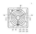
- FIG. 2 is a plan view of the blower 1.
- FIG. 3 is a front view of the blower 1.
- FIG. 4 is an exploded perspective view of the blower 1.
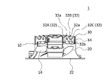
- FIG. FIG. 5 is a cross-sectional view taken along line VV of FIG. Note that the arrows in FIG. 1 indicate an example of air flow. 1 and 5, illustration of the decorative grille 26 is omitted.
- the blower 1 includes a motor 10 , an axial fan 14 , a duct portion 20 and an air passage component 30 .
- the motor 10 has a rotating shaft 12 extending vertically.
- An axial fan 14 is attached to the rotating shaft 12 .
- a rotating shaft 12 extends vertically downward from a motor 10
- an axial fan 14 is provided at the lower end of the rotating shaft 12 .
- the axial fan 14 is, for example, a propeller fan and has a plurality of blades. As an example, the number of blades of the axial fan 14 is set to five.
- the rotating shaft 12 rotates around the central axis C1 of the rotating shaft 12 extending in the vertical direction, and accordingly the axial flow fan 14 rotates around the central axis C1.
- the axial fan 14 is configured such that air flows upward in the vertical direction around the axial fan 14 as the axial fan 14 rotates.
- the duct part 20 is formed in a cylindrical shape and accommodates the axial flow fan 14 inside.
- the duct portion 20 has a substantially cylindrical shape extending in the vertical direction.
- the lower end of the duct portion 20 is provided with an opening serving as a suction port 22 for sucking air into the inside of the duct portion 20 .
- a decorative grill 26 is provided below the duct portion 20 so as to cover the suction port 22 .
- the decorative grill 26 is provided with an opening that communicates with the suction port 22 .
- the air passage component 30 covers above the axial fan 14 . Further, the air passage component 30 forms a ventilation port 36 that communicates with the inside of the duct portion 20 . In the present embodiment, the air passage component 30 is configured to be attachable to and detachable from the duct portion 20 . Also, the air passage component 30 supports the motor 10 at its central portion.
- the air duct component 30 is made of, for example, a resin material.
- the air passage component 30 has a guide portion 32 and side wall portions 34 .
- the guide portion 32 changes the direction of the air flow generated by the rotation of the axial fan 14 .
- the guide portion 32 extends outward in a radial direction about the central axis C1 of the rotating shaft 12 as it goes upward.
- the guide portion 32 is provided in an annular shape coaxial with the rotating shaft 12 .
- the guide portion 32 is formed in a plate shape, and curves from the inner side to the outer side in the radial direction as it goes upward. Such a guide portion 32 smoothly changes the vertically upward air flow generated by the axial fan 14 into a radially outward flow.
- the air passage component 30 has a plurality of guide portions 32, and as the guide portions 32, guide portions 32A, 32B and 32C are provided.
- the guide portion 32A, the guide portion 32B and the guide portion 32C are arranged in the radial direction.
- the guide portion 32B is arranged radially outside the guide portion 32A
- the guide portion 32C is arranged radially outside the guide portion 32B.
- the radial outer end 32a of the guide portion 32A is arranged above the radial inner end 32b of the guide portion 32B.
- the radial outer end 32a of the guide portion 32B is arranged above the radial inner end 32b of the guide portion 32C.
- the plurality of guide portions 32 are supported by a plurality of radially extending support portions 38 .
- a plurality of guide portions 32 are supported by three support portions 38 .
- the three support portions 38 are arranged at intervals of 120 degrees around the rotating shaft 12 .
- the supports 38 allow the guides 32 to be placed in the correct designed position. Specifically, the support portion 38 suppresses distortion that occurs due to a partial cooling time difference during cooling when the air duct component 30 is molded from a resin material, or reduces distortion that occurs due to handling during installation. can be suppressed.
- the side wall portion 34 is annularly arranged around the rotating shaft 12 in the upper portion of the duct portion 20 .
- the side wall portion 34 is connected to the upper portion of the duct portion 20 and formed in a cylindrical shape having the same diameter as the upper portion of the duct portion 20 .
- a guide portion 32 is provided on the upper portion of the side wall portion 34 .
- the ventilation port 36 is arranged at the radially outer end portion 32a of the guide portion 32 and opens radially outward.
- a plurality of ventilation openings 36 are also provided in the air passage component 30.
- As the ventilation openings 36 a ventilation opening 36A and a ventilation opening 36B are provided. ing.
- the ventilation port 36A is arranged radially outward of the radially outer end 32a of the radially inner guide portion 32A of the two radially adjacent guide portions 32A and 32B. and the radially inner end portion 32b of the guide portion 32B.
- the ventilation port 36B is located radially outward of the radially outer end 32a of the radially inner guide portion 32B of the two radially adjacent guide portions 32B and 32C. It is arranged between the radially inner end portion 32b of the arranged guide portion 32C.
- the ventilation port 36 is arranged at a position that is hidden by the air duct structural member 30 when viewed vertically downward from above the air duct structural member 30 .
- the ventilation port 36A arranged at the radially outer end 32a of the guide portion 32A the position of the radially outer end 32a of the guide portion 32A and the position of the end 32a of the guide portion 32A
- the end portion 32a of the guide portion 32A and the end portion 32b of the guide portion 32B are arranged such that the position of the radially inner end portion 32b of the guide portion 32B disposed below vertically overlaps.
- the inside of the duct portion 20 cannot be seen through the ventilation port 36A, and there is no gap between the guide portions 32A and 32B.
- the end portion 32a of the guide portion 32B and the end portion 32b of the guide portion 32C are arranged such that the position of the end portion 32b overlaps in the vertical direction.
- a side air vent 37 is formed in the side wall portion 34 .
- the side air vent 37 communicates with the inside of the duct portion 20 and opens radially outward.
- the side ventilation openings 37 are arranged at a position hidden by the air-path-constituting member 30 when viewed downward in the vertical direction from above the air-path-constituting member 30 .
- the side air vent 37 is arranged along the vertical direction below the radially outer end portion 32a of the radially outermost guide portion 32C. Therefore, the side vents 37 are arranged so as not to be seen when viewed downward in the vertical direction from above the air passage component 30 .
- the blower 1 in the present embodiment is installed in a ceiling space 44 formed between a ceiling material 40 of a house or the like and a ceiling space upper surface material 42 .
- the air blower 1 sucks air in the room 46 from the suction port 22 of the duct part 20 through the decorative grille 26 and blows the air into the ceiling space 44. ⁇ Thereby, the air in the room 46 is cleaned and the temperature and humidity are adjusted.
- the height (vertical dimension) of the fan 1 is preferably 130 mm or less.
- the blower 1 includes the motor 10 having the rotating shaft 12 extending in the vertical direction, the axial fan 14 attached to the rotating shaft 12, and the axial fan 14 inside. It has a cylindrical duct portion 20 to accommodate, and a guide portion 32 that covers the upper side of the axial fan 14 and changes the direction of the air flow generated by the rotation of the axial fan 14, and the inside of the duct portion 20 and the guide portion 32. and an air passage forming member 30 forming a communicating air passage opening 36, and the air passage opening 36 is arranged at a position hidden by the guide portion 32 when viewed vertically downward from above the air passage constituent member 30. There is.
- the ventilation port 36 is arranged at a position hidden by the guide part 32 when viewed downward in the vertical direction from above the air duct structure member 30. Therefore, when viewed from above the air duct structure member 30, The inside of the blower 1 is made invisible. Therefore, even if dust falls from above while the operation of the blower 1 is stopped, it can be prevented from accumulating on the upper surface of the air passage component 30 and flowing into the inside of the blower 1 through the ventilation port 36. ⁇ As a result, it is possible to prevent the inside of the blower 1 from becoming dirty.
- the guide portion 32 extends outward in the radial direction centering on the central axis C1 of the rotating shaft 12 as it goes upward. and open radially outward. With such a configuration, the vertical air flow generated by the rotation of the axial fan 14 can be changed into a radially inclined flow while suppressing an increase in flow path resistance by the guide portion 32 .
- the air passage structure member 30 has a plurality of guide portions 32 arranged in the radial direction. Between the radially outer end portion 32a of the guide portion 32 arranged radially inward and the radially inner end portion 32b of the guide portion 32 arranged radially outwardly, a ventilation hole is provided. 36 are arranged. In this way, by arranging a plurality of guide portions 32 in the radial direction and providing a plurality of ventilation holes 36 corresponding thereto, the height of the guide portion 32 is reduced compared to the case where one guide portion 32 changes the air flow. (dimension in the vertical direction) can be reduced. As a result, the overall height of the blower 1 can be reduced, and the blower 1 can be arranged in a narrow space such as the ceiling space 44 or the like.
- the blower 1 further includes a plurality of support portions 38 that extend in the radial direction and support the plurality of guide portions 32, and the greatest common divisor of the number of support portions 38 and the number of blades of the axial fan 14 is one.
- the number of support portions 38 is three, and the number of blades of axial fan 14 is five. has become 1.
- the operating noise of the blower 1 can be reduced. If the greatest common divisor of the number of support portions 38 and the number of blades of the axial fan 14 is greater than 1, the support portions 38 and the blades of the axial fan 14 come close to each other when the axial fan 14 rotates. Since there are a plurality of numbers to be driven, wind noise is generated at a plurality of locations at the same time, resulting in increased operating noise. On the other hand, by setting the greatest common divisor of the number of support portions 38 and the number of blades of the axial fan 14 to 1 as described above, the generation of wind noise can be suppressed, and the operating noise can be reduced. .
- the air passage component 30 has a side wall portion 34 annularly arranged around the rotating shaft 12 in the upper portion of the duct portion 20.
- the side wall portion 34 communicates with the inside of the duct portion 20 and extends radially outward.
- a side ventilation port 37 is formed that opens toward. In this manner, by providing the side ventilation openings 37 in the side wall portion 34 in addition to the ventilation openings 36, the opening area through which the air flow passes can be increased. Thereby, noise during operation of the blower 1 can be reduced.
- the air passage component 30 is attachable to and detachable from the duct portion 20 .
- the air duct component 30 is fixed to the duct section 20 using screws, and the air duct component 30 can be removed from the duct section 20 by loosening the screws.
- dust adhering to the upper surface of the air duct forming member 30 can be easily cleaned by removing the air duct forming member 30 .
- dust and the like adhering to the upper surface of the air duct forming member 30 can be easily removed, it is possible to suppress the dust and the like adhering to the upper surface of the air duct forming member 30 from falling inside, making the inside of the fan 1 less likely to become dirty. be able to.
- the present invention is not limited to this.
- the end portion 32a of the guide portion 32A overlaps the guide portion 32B in the vertical direction
- the end portion 32b of the guide portion 32B may be located radially inside the end portion 32a of the guide portion 32A.
- FIG. 6 is a cross-sectional view of fan 101 in this embodiment.
- FIG. 6 shows a cross section at the same position as the cross section shown in FIG. 5 in the first embodiment.
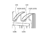
- 7 is an enlarged view of part A in FIG. 6.
- FIG. In this embodiment, the description of the same parts as in the first embodiment will be omitted.
- a blower 101 according to the present embodiment differs from the blower 1 according to Embodiment 1 in that a concave portion 133 is formed in a radially inner end portion 132b of a guide portion 132 .
- a guide portion 132A, a guide portion 132B, and a guide portion 132C are arranged from the inner side to the outer side in the radial direction.
- the radially inner end portion 132b of the radially outer guide portion 132C is provided with the guide portion 132C.
- a concave portion 133 whose upper surface is concave downward is formed.
- a concave portion 133 is formed in the radially inner end portion 132b of the radially outer guide portion 132B.
- the recess 133 is formed in the radially inner end portion 132b of the guide portion 132 . Since the guide portion 132 is inclined so as to become lower from the outer side to the inner side in the radial direction, dust accumulated on the upper surface of the guide portion 132 moves radially inward along the upper surface of the guide portion 132. Even if dust or the like falling from above moves radially inward along the upper surface of the guide portion 132 , the dust or the like can be received by the concave portion 133 . As a result, dust or the like can be prevented from flowing into the inside of the fan 1 from the upper surface of the guide portion 132, and the inside of the fan 1 can be prevented from becoming dirty.
- Air passage component 32, 32A, 32B, 32C, 132, 132A, 132B, 132C Guide part, 32a, 32b, 132b End part, 34 Side wall part, 36, 36A, 36B Ventilation port, 37 Side ventilation port, 38 Support part, 40 Ceiling material, 42 Top surface material for space above ceiling, 44 Space above ceiling, 46 Interior , 133 concave portion, C1 central axis.
Landscapes
- Engineering & Computer Science (AREA)
- Mechanical Engineering (AREA)
- General Engineering & Computer Science (AREA)
- Chemical & Material Sciences (AREA)
- Combustion & Propulsion (AREA)
- Structures Of Non-Positive Displacement Pumps (AREA)
Priority Applications (2)
| Application Number | Priority Date | Filing Date | Title |
|---|---|---|---|
| PCT/JP2021/004363 WO2022168271A1 (ja) | 2021-02-05 | 2021-02-05 | 送風機 |
| JP2022579269A JP7416290B2 (ja) | 2021-02-05 | 2021-02-05 | 送風機 |
Applications Claiming Priority (1)
| Application Number | Priority Date | Filing Date | Title |
|---|---|---|---|
| PCT/JP2021/004363 WO2022168271A1 (ja) | 2021-02-05 | 2021-02-05 | 送風機 |
Publications (1)
| Publication Number | Publication Date |
|---|---|
| WO2022168271A1 true WO2022168271A1 (ja) | 2022-08-11 |
Family
ID=82742131
Family Applications (1)
| Application Number | Title | Priority Date | Filing Date |
|---|---|---|---|
| PCT/JP2021/004363 WO2022168271A1 (ja) | 2021-02-05 | 2021-02-05 | 送風機 |
Country Status (2)
| Country | Link |
|---|---|
| JP (1) | JP7416290B2 (en, 2012) |
| WO (1) | WO2022168271A1 (en, 2012) |
Cited By (1)
| Publication number | Priority date | Publication date | Assignee | Title |
|---|---|---|---|---|
| WO2024095722A1 (ja) * | 2022-10-31 | 2024-05-10 | パナソニックIpマネジメント株式会社 | 換気装置 |
Citations (5)
| Publication number | Priority date | Publication date | Assignee | Title |
|---|---|---|---|---|
| JPS56150010U (en, 2012) * | 1980-04-11 | 1981-11-11 | ||
| JPH0188250U (en, 2012) * | 1987-11-27 | 1989-06-12 | ||
| WO2015025484A1 (ja) * | 2013-08-21 | 2015-02-26 | パナソニックIpマネジメント株式会社 | 換気装置 |
| WO2017038484A1 (ja) * | 2015-08-31 | 2017-03-09 | 株式会社日立製作所 | クリーンルーム用空調システム及びそれに用いられる排気ユニット |
| JP2017125641A (ja) * | 2016-01-13 | 2017-07-20 | 株式会社日立製作所 | クリーンルーム用排気ユニット及びそれを備えるクリーンルーム用空調システム |
-
2021
- 2021-02-05 JP JP2022579269A patent/JP7416290B2/ja active Active
- 2021-02-05 WO PCT/JP2021/004363 patent/WO2022168271A1/ja active Application Filing
Patent Citations (5)
| Publication number | Priority date | Publication date | Assignee | Title |
|---|---|---|---|---|
| JPS56150010U (en, 2012) * | 1980-04-11 | 1981-11-11 | ||
| JPH0188250U (en, 2012) * | 1987-11-27 | 1989-06-12 | ||
| WO2015025484A1 (ja) * | 2013-08-21 | 2015-02-26 | パナソニックIpマネジメント株式会社 | 換気装置 |
| WO2017038484A1 (ja) * | 2015-08-31 | 2017-03-09 | 株式会社日立製作所 | クリーンルーム用空調システム及びそれに用いられる排気ユニット |
| JP2017125641A (ja) * | 2016-01-13 | 2017-07-20 | 株式会社日立製作所 | クリーンルーム用排気ユニット及びそれを備えるクリーンルーム用空調システム |
Cited By (1)
| Publication number | Priority date | Publication date | Assignee | Title |
|---|---|---|---|---|
| WO2024095722A1 (ja) * | 2022-10-31 | 2024-05-10 | パナソニックIpマネジメント株式会社 | 換気装置 |
Also Published As
| Publication number | Publication date |
|---|---|
| JPWO2022168271A1 (en, 2012) | 2022-08-11 |
| JP7416290B2 (ja) | 2024-01-17 |
Similar Documents
| Publication | Publication Date | Title |
|---|---|---|
| US20220011009A1 (en) | Air cleaner | |
| JP4946352B2 (ja) | 送風装置及び空調装置 | |
| JP4432474B2 (ja) | 遠心送風機の羽根車及びそれを備えた遠心送風機 | |
| EP2535594A1 (en) | Centrifugal blower | |
| US11892194B2 (en) | Air cleaner | |
| WO2012101823A1 (ja) | サーキュレータ | |
| KR20160051095A (ko) | 공기조화기 | |
| KR20170057028A (ko) | 송풍장치 및 이를 포함하는 공기청정기 | |
| KR20080045568A (ko) | 터보팬 및 이를 갖춘 공기조화기 | |
| WO2022168271A1 (ja) | 送風機 | |
| CN113915710B (zh) | 空气净化器 | |
| KR101912634B1 (ko) | 공기조화기 | |
| JP5304719B2 (ja) | 車両用空調装置の送風ユニット | |
| JP5195983B2 (ja) | 遠心送風機 | |
| JP2013036444A (ja) | 遠心送風機 | |
| JPH0842875A (ja) | 送風装置の安全カバー | |
| JP2925851B2 (ja) | 天井用換気扇 | |
| KR102370822B1 (ko) | 공기조화기용 원심팬 및 이를 구비하는 천장형 공기조화기 | |
| JPWO2022168271A5 (en, 2012) | ||
| JP6340225B2 (ja) | 遠心ファン | |
| JP2012013090A (ja) | 送風装置 | |
| WO2024095722A1 (ja) | 換気装置 | |
| KR102627657B1 (ko) | 공기청정기 | |
| JPH0682074A (ja) | 天井用換気扇 | |
| CN219875245U (zh) | 电机组件、风机组件及吸力装置 |
Legal Events
| Date | Code | Title | Description |
|---|---|---|---|
| 121 | Ep: the epo has been informed by wipo that ep was designated in this application |
Ref document number: 21924666 Country of ref document: EP Kind code of ref document: A1 |
|
| ENP | Entry into the national phase |
Ref document number: 2022579269 Country of ref document: JP Kind code of ref document: A |
|
| NENP | Non-entry into the national phase |
Ref country code: DE |
|
| 122 | Ep: pct application non-entry in european phase |
Ref document number: 21924666 Country of ref document: EP Kind code of ref document: A1 |