WO2022168271A1 - 送風機 - Google Patents
送風機 Download PDFInfo
- Publication number
- WO2022168271A1 WO2022168271A1 PCT/JP2021/004363 JP2021004363W WO2022168271A1 WO 2022168271 A1 WO2022168271 A1 WO 2022168271A1 JP 2021004363 W JP2021004363 W JP 2021004363W WO 2022168271 A1 WO2022168271 A1 WO 2022168271A1
- Authority
- WO
- WIPO (PCT)
- Prior art keywords
- guide portion
- guide
- air passage
- blower
- axial fan
- Prior art date
Links
- 238000009423 ventilation Methods 0.000 claims abstract description 40
- 239000000463 material Substances 0.000 abstract description 8
- 239000000470 constituent Substances 0.000 abstract description 3
- 239000000428 dust Substances 0.000 description 13
- 238000001816 cooling Methods 0.000 description 2
- 238000010586 diagram Methods 0.000 description 2
- 239000011347 resin Substances 0.000 description 2
- 229920005989 resin Polymers 0.000 description 2
- 238000007664 blowing Methods 0.000 description 1
- 230000004941 influx Effects 0.000 description 1
- 238000009434 installation Methods 0.000 description 1
- 230000004048 modification Effects 0.000 description 1
- 238000012986 modification Methods 0.000 description 1
Images


Classifications
-
- F—MECHANICAL ENGINEERING; LIGHTING; HEATING; WEAPONS; BLASTING
- F04—POSITIVE - DISPLACEMENT MACHINES FOR LIQUIDS; PUMPS FOR LIQUIDS OR ELASTIC FLUIDS
- F04D—NON-POSITIVE-DISPLACEMENT PUMPS
- F04D25/00—Pumping installations or systems
- F04D25/02—Units comprising pumps and their driving means
- F04D25/08—Units comprising pumps and their driving means the working fluid being air, e.g. for ventilation
-
- F—MECHANICAL ENGINEERING; LIGHTING; HEATING; WEAPONS; BLASTING
- F24—HEATING; RANGES; VENTILATING
- F24F—AIR-CONDITIONING; AIR-HUMIDIFICATION; VENTILATION; USE OF AIR CURRENTS FOR SCREENING
- F24F7/00—Ventilation
- F24F7/04—Ventilation with ducting systems, e.g. by double walls; with natural circulation
- F24F7/06—Ventilation with ducting systems, e.g. by double walls; with natural circulation with forced air circulation, e.g. by fan positioning of a ventilator in or against a conduit
- F24F7/10—Ventilation with ducting systems, e.g. by double walls; with natural circulation with forced air circulation, e.g. by fan positioning of a ventilator in or against a conduit with air supply, or exhaust, through perforated wall, floor or ceiling
Definitions
- the present disclosure relates to blowers.
- Patent Literature 1 describes a ventilation fan having a propeller fan suspended in a ventilation hole in a ceiling wall and a driving motor attached to the lower end of the fan.
- the drive motor is supported by mounting legs provided on the ceiling wall.
- the present disclosure has been made in order to solve the above-described problems, and provides a blower capable of suppressing the inflow of dust and the like to the inside of the blower.
- the blower according to the present disclosure includes a motor having a rotating shaft extending in a vertical direction, an axial fan attached to the rotating shaft, a cylindrical duct part that accommodates the axial fan inside, and a an air passage component covering the duct, having a guide portion for changing the direction of air flow generated by the rotation of the axial fan, and forming a ventilation port communicating with the inside of the duct portion, wherein the ventilation port comprises: It is arranged at a position hidden by the guide portion when viewed vertically downward from above the air passage component.
- FIG. 1 is a schematic diagram of a blower showing Embodiment 1.
- FIG. 1 is a plan view of a blower showing Embodiment 1.
- FIG. 1 is a front view of a blower showing Embodiment 1.
- FIG. 1 is an exploded perspective view of a blower showing Embodiment 1.
- FIG. 3 is a cross-sectional view taken along line VV of FIG. 2;
- FIG. 8 is a cross-sectional view of a blower showing Embodiment 2; 7 is an enlarged view of part A of FIG. 6.
- FIG. 1 is a schematic diagram of a blower showing Embodiment 1.
- FIG. 1 is a plan view of a blower showing Embodiment 1.
- FIG. 1 is a front view of a blower showing Embodiment 1.
- FIG. 1 is an exploded perspective view of a blower showing Embodiment 1.
- FIG. 3 is a cross-sectional view taken along line VV of FIG. 2;
- FIG. 1 is a schematic diagram of a fan 1 according to this embodiment.
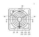
- FIG. 2 is a plan view of the blower 1.
- FIG. 3 is a front view of the blower 1.
- FIG. 4 is an exploded perspective view of the blower 1.
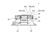
- FIG. FIG. 5 is a cross-sectional view taken along line VV of FIG. Note that the arrows in FIG. 1 indicate an example of air flow. 1 and 5, illustration of the decorative grille 26 is omitted.
- the blower 1 includes a motor 10 , an axial fan 14 , a duct portion 20 and an air passage component 30 .
- the motor 10 has a rotating shaft 12 extending vertically.
- An axial fan 14 is attached to the rotating shaft 12 .
- a rotating shaft 12 extends vertically downward from a motor 10
- an axial fan 14 is provided at the lower end of the rotating shaft 12 .
- the axial fan 14 is, for example, a propeller fan and has a plurality of blades. As an example, the number of blades of the axial fan 14 is set to five.
- the rotating shaft 12 rotates around the central axis C1 of the rotating shaft 12 extending in the vertical direction, and accordingly the axial flow fan 14 rotates around the central axis C1.
- the axial fan 14 is configured such that air flows upward in the vertical direction around the axial fan 14 as the axial fan 14 rotates.
- the duct part 20 is formed in a cylindrical shape and accommodates the axial flow fan 14 inside.
- the duct portion 20 has a substantially cylindrical shape extending in the vertical direction.
- the lower end of the duct portion 20 is provided with an opening serving as a suction port 22 for sucking air into the inside of the duct portion 20 .
- a decorative grill 26 is provided below the duct portion 20 so as to cover the suction port 22 .
- the decorative grill 26 is provided with an opening that communicates with the suction port 22 .
- the air passage component 30 covers above the axial fan 14 . Further, the air passage component 30 forms a ventilation port 36 that communicates with the inside of the duct portion 20 . In the present embodiment, the air passage component 30 is configured to be attachable to and detachable from the duct portion 20 . Also, the air passage component 30 supports the motor 10 at its central portion.
- the air duct component 30 is made of, for example, a resin material.
- the air passage component 30 has a guide portion 32 and side wall portions 34 .
- the guide portion 32 changes the direction of the air flow generated by the rotation of the axial fan 14 .
- the guide portion 32 extends outward in a radial direction about the central axis C1 of the rotating shaft 12 as it goes upward.
- the guide portion 32 is provided in an annular shape coaxial with the rotating shaft 12 .
- the guide portion 32 is formed in a plate shape, and curves from the inner side to the outer side in the radial direction as it goes upward. Such a guide portion 32 smoothly changes the vertically upward air flow generated by the axial fan 14 into a radially outward flow.
- the air passage component 30 has a plurality of guide portions 32, and as the guide portions 32, guide portions 32A, 32B and 32C are provided.
- the guide portion 32A, the guide portion 32B and the guide portion 32C are arranged in the radial direction.
- the guide portion 32B is arranged radially outside the guide portion 32A
- the guide portion 32C is arranged radially outside the guide portion 32B.
- the radial outer end 32a of the guide portion 32A is arranged above the radial inner end 32b of the guide portion 32B.
- the radial outer end 32a of the guide portion 32B is arranged above the radial inner end 32b of the guide portion 32C.
- the plurality of guide portions 32 are supported by a plurality of radially extending support portions 38 .
- a plurality of guide portions 32 are supported by three support portions 38 .
- the three support portions 38 are arranged at intervals of 120 degrees around the rotating shaft 12 .
- the supports 38 allow the guides 32 to be placed in the correct designed position. Specifically, the support portion 38 suppresses distortion that occurs due to a partial cooling time difference during cooling when the air duct component 30 is molded from a resin material, or reduces distortion that occurs due to handling during installation. can be suppressed.
- the side wall portion 34 is annularly arranged around the rotating shaft 12 in the upper portion of the duct portion 20 .
- the side wall portion 34 is connected to the upper portion of the duct portion 20 and formed in a cylindrical shape having the same diameter as the upper portion of the duct portion 20 .
- a guide portion 32 is provided on the upper portion of the side wall portion 34 .
- the ventilation port 36 is arranged at the radially outer end portion 32a of the guide portion 32 and opens radially outward.
- a plurality of ventilation openings 36 are also provided in the air passage component 30.
- As the ventilation openings 36 a ventilation opening 36A and a ventilation opening 36B are provided. ing.
- the ventilation port 36A is arranged radially outward of the radially outer end 32a of the radially inner guide portion 32A of the two radially adjacent guide portions 32A and 32B. and the radially inner end portion 32b of the guide portion 32B.
- the ventilation port 36B is located radially outward of the radially outer end 32a of the radially inner guide portion 32B of the two radially adjacent guide portions 32B and 32C. It is arranged between the radially inner end portion 32b of the arranged guide portion 32C.
- the ventilation port 36 is arranged at a position that is hidden by the air duct structural member 30 when viewed vertically downward from above the air duct structural member 30 .
- the ventilation port 36A arranged at the radially outer end 32a of the guide portion 32A the position of the radially outer end 32a of the guide portion 32A and the position of the end 32a of the guide portion 32A
- the end portion 32a of the guide portion 32A and the end portion 32b of the guide portion 32B are arranged such that the position of the radially inner end portion 32b of the guide portion 32B disposed below vertically overlaps.
- the inside of the duct portion 20 cannot be seen through the ventilation port 36A, and there is no gap between the guide portions 32A and 32B.
- the end portion 32a of the guide portion 32B and the end portion 32b of the guide portion 32C are arranged such that the position of the end portion 32b overlaps in the vertical direction.
- a side air vent 37 is formed in the side wall portion 34 .
- the side air vent 37 communicates with the inside of the duct portion 20 and opens radially outward.
- the side ventilation openings 37 are arranged at a position hidden by the air-path-constituting member 30 when viewed downward in the vertical direction from above the air-path-constituting member 30 .
- the side air vent 37 is arranged along the vertical direction below the radially outer end portion 32a of the radially outermost guide portion 32C. Therefore, the side vents 37 are arranged so as not to be seen when viewed downward in the vertical direction from above the air passage component 30 .
- the blower 1 in the present embodiment is installed in a ceiling space 44 formed between a ceiling material 40 of a house or the like and a ceiling space upper surface material 42 .
- the air blower 1 sucks air in the room 46 from the suction port 22 of the duct part 20 through the decorative grille 26 and blows the air into the ceiling space 44. ⁇ Thereby, the air in the room 46 is cleaned and the temperature and humidity are adjusted.
- the height (vertical dimension) of the fan 1 is preferably 130 mm or less.
- the blower 1 includes the motor 10 having the rotating shaft 12 extending in the vertical direction, the axial fan 14 attached to the rotating shaft 12, and the axial fan 14 inside. It has a cylindrical duct portion 20 to accommodate, and a guide portion 32 that covers the upper side of the axial fan 14 and changes the direction of the air flow generated by the rotation of the axial fan 14, and the inside of the duct portion 20 and the guide portion 32. and an air passage forming member 30 forming a communicating air passage opening 36, and the air passage opening 36 is arranged at a position hidden by the guide portion 32 when viewed vertically downward from above the air passage constituent member 30. There is.
- the ventilation port 36 is arranged at a position hidden by the guide part 32 when viewed downward in the vertical direction from above the air duct structure member 30. Therefore, when viewed from above the air duct structure member 30, The inside of the blower 1 is made invisible. Therefore, even if dust falls from above while the operation of the blower 1 is stopped, it can be prevented from accumulating on the upper surface of the air passage component 30 and flowing into the inside of the blower 1 through the ventilation port 36. ⁇ As a result, it is possible to prevent the inside of the blower 1 from becoming dirty.
- the guide portion 32 extends outward in the radial direction centering on the central axis C1 of the rotating shaft 12 as it goes upward. and open radially outward. With such a configuration, the vertical air flow generated by the rotation of the axial fan 14 can be changed into a radially inclined flow while suppressing an increase in flow path resistance by the guide portion 32 .
- the air passage structure member 30 has a plurality of guide portions 32 arranged in the radial direction. Between the radially outer end portion 32a of the guide portion 32 arranged radially inward and the radially inner end portion 32b of the guide portion 32 arranged radially outwardly, a ventilation hole is provided. 36 are arranged. In this way, by arranging a plurality of guide portions 32 in the radial direction and providing a plurality of ventilation holes 36 corresponding thereto, the height of the guide portion 32 is reduced compared to the case where one guide portion 32 changes the air flow. (dimension in the vertical direction) can be reduced. As a result, the overall height of the blower 1 can be reduced, and the blower 1 can be arranged in a narrow space such as the ceiling space 44 or the like.
- the blower 1 further includes a plurality of support portions 38 that extend in the radial direction and support the plurality of guide portions 32, and the greatest common divisor of the number of support portions 38 and the number of blades of the axial fan 14 is one.
- the number of support portions 38 is three, and the number of blades of axial fan 14 is five. has become 1.
- the operating noise of the blower 1 can be reduced. If the greatest common divisor of the number of support portions 38 and the number of blades of the axial fan 14 is greater than 1, the support portions 38 and the blades of the axial fan 14 come close to each other when the axial fan 14 rotates. Since there are a plurality of numbers to be driven, wind noise is generated at a plurality of locations at the same time, resulting in increased operating noise. On the other hand, by setting the greatest common divisor of the number of support portions 38 and the number of blades of the axial fan 14 to 1 as described above, the generation of wind noise can be suppressed, and the operating noise can be reduced. .
- the air passage component 30 has a side wall portion 34 annularly arranged around the rotating shaft 12 in the upper portion of the duct portion 20.
- the side wall portion 34 communicates with the inside of the duct portion 20 and extends radially outward.
- a side ventilation port 37 is formed that opens toward. In this manner, by providing the side ventilation openings 37 in the side wall portion 34 in addition to the ventilation openings 36, the opening area through which the air flow passes can be increased. Thereby, noise during operation of the blower 1 can be reduced.
- the air passage component 30 is attachable to and detachable from the duct portion 20 .
- the air duct component 30 is fixed to the duct section 20 using screws, and the air duct component 30 can be removed from the duct section 20 by loosening the screws.
- dust adhering to the upper surface of the air duct forming member 30 can be easily cleaned by removing the air duct forming member 30 .
- dust and the like adhering to the upper surface of the air duct forming member 30 can be easily removed, it is possible to suppress the dust and the like adhering to the upper surface of the air duct forming member 30 from falling inside, making the inside of the fan 1 less likely to become dirty. be able to.
- the present invention is not limited to this.
- the end portion 32a of the guide portion 32A overlaps the guide portion 32B in the vertical direction
- the end portion 32b of the guide portion 32B may be located radially inside the end portion 32a of the guide portion 32A.
- FIG. 6 is a cross-sectional view of fan 101 in this embodiment.
- FIG. 6 shows a cross section at the same position as the cross section shown in FIG. 5 in the first embodiment.
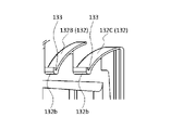
- 7 is an enlarged view of part A in FIG. 6.
- FIG. In this embodiment, the description of the same parts as in the first embodiment will be omitted.
- a blower 101 according to the present embodiment differs from the blower 1 according to Embodiment 1 in that a concave portion 133 is formed in a radially inner end portion 132b of a guide portion 132 .
- a guide portion 132A, a guide portion 132B, and a guide portion 132C are arranged from the inner side to the outer side in the radial direction.
- the radially inner end portion 132b of the radially outer guide portion 132C is provided with the guide portion 132C.
- a concave portion 133 whose upper surface is concave downward is formed.
- a concave portion 133 is formed in the radially inner end portion 132b of the radially outer guide portion 132B.
- the recess 133 is formed in the radially inner end portion 132b of the guide portion 132 . Since the guide portion 132 is inclined so as to become lower from the outer side to the inner side in the radial direction, dust accumulated on the upper surface of the guide portion 132 moves radially inward along the upper surface of the guide portion 132. Even if dust or the like falling from above moves radially inward along the upper surface of the guide portion 132 , the dust or the like can be received by the concave portion 133 . As a result, dust or the like can be prevented from flowing into the inside of the fan 1 from the upper surface of the guide portion 132, and the inside of the fan 1 can be prevented from becoming dirty.
- Air passage component 32, 32A, 32B, 32C, 132, 132A, 132B, 132C Guide part, 32a, 32b, 132b End part, 34 Side wall part, 36, 36A, 36B Ventilation port, 37 Side ventilation port, 38 Support part, 40 Ceiling material, 42 Top surface material for space above ceiling, 44 Space above ceiling, 46 Interior , 133 concave portion, C1 central axis.
Landscapes
- Engineering & Computer Science (AREA)
- Mechanical Engineering (AREA)
- General Engineering & Computer Science (AREA)
- Chemical & Material Sciences (AREA)
- Combustion & Propulsion (AREA)
- Structures Of Non-Positive Displacement Pumps (AREA)
Abstract
送風機(1)は、鉛直方向に延びる回転軸(12)を有するモータ(10)と、回転軸(12)に取り付けられた軸流ファン(14)と、軸流ファン(14)を内部に収容する筒状のダクト部(20)と、軸流ファン(14)の上方を覆っており、軸流ファン(14)の回転により生じる空気の流れの向きを変化させる案内部(32)を有し、ダクト部(20)の内部と連通する通風口(36)を形成する風路構成材(30)と、を備える。通風口(36)は、風路構成材(30)の上方から鉛直方向の下向きに見た場合に、案内部(32)によって隠れる位置に配されている。
Description
本開示は、送風機に関する。
従来、部屋等の天井に設置されて、室内の換気等を行う送風機が知られている。例えば特許文献1には、天井壁の換気穴内に垂下状態に設けたプロペラファンと、このファンを下端に取り付けた駆動用モータと、を有する換気扇が記載されている。駆動用モータは、天井壁に設けられた取付け脚に支持されている。
特許文献1に記載の換気扇では、プロペラファンの上方に位置する取付け脚に開口が設けられており、この開口を通って空気がプロペラファンに吸い込まれる。このため、換気扇の運転停止中には、この開口を通じて天井裏の塵や埃が換気扇内に流入し、換気扇の内部が汚れる可能性があった。
本開示は、上記のような課題を解決するためになされたもので、内部に埃等が流入して汚れることを抑制できる送風機を得るものである。
本開示に係る送風機は、鉛直方向に延びる回転軸を有するモータと、回転軸に取り付けられた軸流ファンと、軸流ファンを内部に収容する筒状のダクト部と、軸流ファンの上方を覆っており、軸流ファンの回転により生じる空気の流れの向きを変化させる案内部を有し、ダクト部の内部と連通する通風口を形成する風路構成材と、を備え、通風口は、風路構成材の上方から鉛直方向の下向きに見た場合に、案内部によって隠れる位置に配されている。
本開示によれば、送風機の内部に埃等が流入して汚れることを抑制できる。
以下、添付図面を参照しながら、実施の形態について説明する。各図において同一または相当する部分には同一の符号を付している。
実施の形態1.
実施の形態1について、図1から図5を参照して説明する。図1は、本実施の形態における送風機1の模式図である。図2は、送風機1の平面図である。図3は、送風機1の正面図である。図4は、送風機1の分解斜視図である。図5は、図2のV-V線に沿った断面図である。なお、図1における矢印は、空気の流れの一例を示している。また、図1および図5では、化粧グリル26の図示を省略している。
実施の形態1について、図1から図5を参照して説明する。図1は、本実施の形態における送風機1の模式図である。図2は、送風機1の平面図である。図3は、送風機1の正面図である。図4は、送風機1の分解斜視図である。図5は、図2のV-V線に沿った断面図である。なお、図1における矢印は、空気の流れの一例を示している。また、図1および図5では、化粧グリル26の図示を省略している。
送風機1は、モータ10と、軸流ファン14と、ダクト部20と、風路構成材30と、を備えている。
モータ10は、鉛直方向に延びる回転軸12を有している。回転軸12には、軸流ファン14が取り付けられている。本実施の形態では、モータ10から鉛直方向の下向きに回転軸12が延びており、回転軸12の下端部に軸流ファン14が設けられている。軸流ファン14は、例えばプロペラファンであり、複数の羽根を有している。軸流ファン14の羽根枚数は、一例として、5枚に設定されている。モータ10を駆動させると、回転軸12が鉛直方向に延びる回転軸12の中心軸C1まわりに回転し、これに伴い、軸流ファン14が中心軸C1まわりに回転する。本実施の形態では、軸流ファン14は、軸流ファン14が回転することにより、軸流ファン14の周囲で鉛直方向の上向きに空気が流れるように構成されている。
ダクト部20は、筒状に形成されており、その内部に軸流ファン14を収容している。本実施の形態では、ダクト部20は、鉛直方向に延びる略円筒形状を有している。ダクト部20の下端には、ダクト部20の内部に空気を吸い込むための吸込口22となる開口が設けられている。ダクト部20の下側には、吸込口22を覆うように化粧グリル26が設けられている。化粧グリル26には、吸込口22に連通する開口が設けられている。
風路構成材30は、軸流ファン14の上方を覆っている。また、風路構成材30は、ダクト部20の内部と連通する通風口36を形成している。本実施の形態では、風路構成材30は、ダクト部20に対して着脱可能に構成されている。また、風路構成材30は、その中央部分においてモータ10を支持している。風路構成材30は、例えば樹脂材料で成形されている。
風路構成材30は、案内部32と、側壁部34と、を有している。案内部32は、軸流ファン14の回転により生じる空気の流れの向きを変化させる。本実施の形態では、案内部32は、上方に向かうにつれて回転軸12の中心軸C1を中心とする径方向の外側に向かって延びている。具体的には、案内部32は、回転軸12と同軸の円環状に設けられている。案内部32は、板状に形成されており、上方に向かうにつれて径方向の内側から外側に湾曲している。このような案内部32により、軸流ファン14によって形成された鉛直方向の上向きの空気の流れを、径方向の外側に向かう流れに滑らかに変化させる。
また、本実施の形態では、風路構成材30は案内部32を複数有しており、案内部32として、案内部32A、案内部32Bおよび案内部32Cが設けられている。案内部32A、案内部32Bおよび案内部32Cは、径方向に配列されている。具体的には、案内部32Aの径方向の外側に案内部32Bが配置され、案内部32Bの径方向の外側に案内部32Cが配置されている。案内部32Aの径方向の外側の端部32aは、案内部32Bの径方向の内側の端部32bの上方に配置されている。案内部32Bの径方向の外側の端部32aは、案内部32Cの径方向の内側の端部32bの上方に配置されている。
複数の案内部32は、径方向に延びる複数の支持部38によって支持されている。本実施の形態では、3つの支持部38により複数の案内部32が支持されている。3つの支持部38は、回転軸12を中心として120度毎に配置されている。支持部38により、複数の案内部32は正しく設計された位置に配置することができる。具体的には、支持部38により、風路構成材30を樹脂材料で成形する場合に冷却時の冷え方の部分的な時間差により発生する歪みを抑えたり、据付け時の取扱いにより発生する歪みを抑えたりすることができる。
側壁部34は、ダクト部20の上部において回転軸12のまわりに環状に配置されている。本実施の形態では、側壁部34は、ダクト部20の上部に接続されており、ダクト部20の上部と同じ径の円筒状に形成されている。側壁部34の上部に案内部32が設けられている。
通風口36は、案内部32における径方向の外側の端部32aに配置されており、径方向の外側に向かって開口している。本実施の形態では、複数の案内部32が設けられているので、通風口36も風路構成材30に複数設けられており、通風口36として、通風口36Aと通風口36Bとが設けられている。通風口36Aは、径方向に隣り合う2つの案内部32Aおよび案内部32Bのうち、径方向の内側に配置された案内部32Aにおける径方向の外側の端部32aと径方向の外側に配置された案内部32Bにおける径方向の内側の端部32bとの間に配置されている。また、通風口36Bは、径方向に隣り合う2つの案内部32Bおよび案内部32Cのうち、径方向の内側に配置された案内部32Bにおける径方向の外側の端部32aと径方向の外側に配置された案内部32Cにおける径方向の内側の端部32bとの間に配置されている。
このような構成で、通風口36は、風路構成材30の上方から鉛直方向の下向きに見た場合に、風路構成材30に隠れる位置に配されている。具体的には、案内部32Aの径方向の外側の端部32aに配置された通風口36Aにおいて、案内部32Aの径方向の外側の端部32aの位置と、案内部32Aの端部32aの下方に配置される案内部32Bの径方向の内側の端部32bの位置とが鉛直方向に重なるように、案内部32Aの端部32aと案内部32Bの端部32bとが配されている。よって、風路構成材30の上方から鉛直方向の下向きに見た場合に、通風口36Aを介してダクト部20の内部が見えず、案内部32Aと案内部32Bとの間に隙間がないように構成されている。通風口36Bについても通風口36Aと同様に、案内部32Bの径方向の外側の端部32aの位置と、案内部32Bの端部32aの下方に配置される案内部32Cの径方向の内側の端部32bの位置とが鉛直方向に重なるように、案内部32Bの端部32aと案内部32Cの端部32bとが配されている。
また、側壁部34には、側面通風口37が形成されている。側面通風口37は、ダクト部20の内部と連通し、径方向の外側に向かって開口している。側面通風口37も通風口36と同様に、風路構成材30の上方から鉛直方向の下向きに見た場合に、風路構成材30に隠れる位置に配されている。具体的には、側面通風口37は、最も径方向の外側に配置された案内部32Cの径方向の外側の端部32aの下側に、鉛直方向に沿って配置されている。よって、側面通風口37は、風路構成材30の上方から鉛直方向の下向きに見た場合に、見えないように配されている。
本実施の形態における送風機1は、例えば、図3に示すように、住宅等の天井材40と天井裏空間上面材42との間に形成される天井裏空間44に設置される。送風機1は、化粧グリル26を介してダクト部20の吸込口22から室内46の空気を吸い込み、天井裏空間44に吹き出す。これにより、室内46の空気の清浄や温湿度の調整を行う。このとき、天井裏空間44に送風機1を収容するために、送風機1の高さ(鉛直方向の寸法)は130mm以下であることが好ましい。
以上に説明したように、本実施の形態に係る送風機1は、鉛直方向に延びる回転軸12を有するモータ10と、回転軸12に取り付けられた軸流ファン14と、軸流ファン14を内部に収容する筒状のダクト部20と、軸流ファン14の上方を覆っており、軸流ファン14の回転により生じる空気の流れの向きを変化させる案内部32を有し、ダクト部20の内部と連通する通風口36を形成する風路構成材30と、を備え、通風口36は、風路構成材30の上方から鉛直方向の下向きに見た場合に、案内部32によって隠れる位置に配されているものである。
このように、通風口36が、風路構成材30の上方から鉛直方向の下向きに見た場合に、案内部32によって隠れる位置に配されているので、風路構成材30の上方から見て送風機1の内部が見えないようになっている。このため、送風機1の運転停止中に上方から塵や埃が落ちてきても風路構成材30の上面に溜まり、通風口36を通って送風機1の内部に流入することを抑制できる。これにより、送風機1の内部が汚れることを抑制できる。
また、従来の技術では、上方に開口する通風口付近に開閉シャッターを設けて、埃等の内部への流入を防止する構成が知られている。しかし、このように構成すると、送風機の運転中に通風口付近に設けられた開閉シャッターに吹出風が衝突して騒音が大きくなるという問題があった。これに対して、本実施の形態に係る送風機1では、開閉シャッターを必要としないので、運転中の騒音の増加という問題を回避できる。
案内部32は、上方に向かうにつれて回転軸12の中心軸C1を中心とする径方向の外側に向かって延びており、通風口36は、案内部32における径方向の外側の端部32aに配置され、径方向の外側に向かって開口している。このような構成により、軸流ファン14の回転により生じた鉛直方向の空気の流れを、案内部32によって流路抵抗の増加を抑制しつつ径方向に傾いた流れに変えることができる。
風路構成材30は、径方向に配列された複数の案内部32を有し、通風口36は、風路構成材30に複数設けられており、径方向に隣り合う2つの案内部32のうち、径方向の内側に配置された案内部32における径方向の外側の端部32aと径方向の外側に配置された案内部32における径方向の内側の端部32bとの間に、通風口36が配置されている。このように、案内部32を径方向に複数配列し、それに対応して通風口36を複数設けることで、1つの案内部32で空気の流れを変える場合に比べて、案内部32の高さ(鉛直方向の寸法)を小さくすることができる。これにより、送風機1の全体の高さを小さくすることができ、例えば天井裏空間44等の狭い空間にも送風機1を配置させることができる。
送風機1は、径方向に延び、複数の案内部32を支持する複数の支持部38をさらに備え、支持部38の数と軸流ファン14の羽根枚数との最大公約数が1である。例えば、本実施の形態では、支持部38の数は3であり、軸流ファン14の羽根枚数は5であるため、支持部38の数と軸流ファン14の羽根枚数との最大公約数は1になっている。
このような構成により、送風機1の運転音を小さくすることができる。仮に、支持部38の数と軸流ファン14の羽根枚数との最大公約数が1よりも大きい場合、軸流ファン14が回転する際に、支持部38と軸流ファン14の羽根とが近接する数が複数存在することになり、風切り音が複数の箇所で同時に発生するため、運転音が大きくなってしまう。これに対して、上述のように支持部38の数と軸流ファン14の羽根枚数との最大公約数を1とすることで、風切り音の発生を抑制でき、運転音を小さくすることができる。
風路構成材30は、ダクト部20の上部において回転軸12のまわりに環状に配置された側壁部34を有し、側壁部34には、ダクト部20の内部と連通し、径方向の外側に向かって開口する側面通風口37が形成されている。このように、通風口36に加えて、側壁部34に側面通風口37を設けることで、空気流が通過する開口面積を増加させることができる。これにより、送風機1の運転中の騒音を小さくすることができる。
風路構成材30は、ダクト部20に対して着脱可能である。本実施の形態では、例えば、ねじを用いて風路構成材30がダクト部20に対して固定されており、ねじを緩めることでダクト部20から風路構成材30を取り外すことができる。このような構成により、風路構成材30を取り外すことで、風路構成材30の上面に付着した塵や埃の清掃を容易に行うことができる。また、風路構成材30の上面に付着した埃等を容易に取り除けるので、風路構成材30の上面に付着した埃等が内部に落下することを抑制でき、送風機1内をより汚れにくくすることができる。
なお、上述した本実施の形態において、案内部32Aの径方向の外側の端部32aの位置と、案内部32Aの端部32aの下方に配置される案内部32Bの径方向の内側の端部32bの位置とが鉛直方向に重なるように、案内部32Aの端部32aと案内部32Bの端部32bとが配されているとしたが、これに限らない。例えば、案内部32Aの端部32aが案内部32Bと鉛直方向に重なっていれば、案内部32Bの端部32bが案内部32Aの端部32aよりも径方向の内側に位置していてもよい。
実施の形態2.
次に、実施の形態2について、図6および図7を参照して説明する。図6は、本実施の形態における送風機101の断面図である。図6は、実施の形態1における図5に示す断面と同じ位置における断面を示している。図7は、図6のA部の拡大図である。なお、本実施の形態のうち、実施の形態1と同様の部分の説明は省略する。
次に、実施の形態2について、図6および図7を参照して説明する。図6は、本実施の形態における送風機101の断面図である。図6は、実施の形態1における図5に示す断面と同じ位置における断面を示している。図7は、図6のA部の拡大図である。なお、本実施の形態のうち、実施の形態1と同様の部分の説明は省略する。
本実施の形態における送風機101は、案内部132の径方向の内側の端部132bに凹部133が形成されている点で、実施の形態1における送風機1と異なっている。具体的には、図6に示すように、送風機101では、案内部132として、径方向の内側から外側にかけて案内部132A、案内部132Bおよび案内部132Cが配列されている。例えば、図7に示すように、径方向に隣り合う案内部132Bおよび案内部132Cのうち、径方向の外側に配置された案内部132Cにおける径方向の内側の端部132bに、案内部132Cの上面が下方に向かって凹む凹部133が形成されている。また、径方向に隣り合う案内部132Aおよび案内部132Bも同様に、径方向の外側に配置された案内部132Bにおける径方向の内側の端部132bに凹部133が形成されている。
このように、案内部132における径方向の内側の端部132bに凹部133が形成されている。案内部132は、径方向の外側から内側にかけて低くなるように傾斜しているので、案内部132の上面に溜まった塵や埃が案内部132の上面を伝って径方向の内側に移動したり、上方から落下してくる埃等が案内部132の上面を伝って径方向の内側に移動したりしたとしても、その埃等を凹部133で受け止めることができる。これにより、埃等が案内部132の上面から送風機1の内部に流入することを防止でき、送風機1の内部が汚れることを防止できる。
なお、上述した各実施の形態を、適宜、組み合わせたり、変形や省略したりすることも、実施の形態で示された技術的思想の範囲に含まれる。
本開示によれば、送風機の内部に埃等が流入して汚れることを抑制できる。
1、101 送風機、10 モータ、12 回転軸、14 軸流ファン、20 ダクト部、22 吸込口、26 化粧グリル、30 風路構成材、32、32A、32B、32C、132、132A、132B、132C 案内部、32a、32b、132b 端部、34 側壁部、36、36A、36B 通風口、37 側面通風口、38 支持部、40 天井材、42 天井裏空間上面材、44 天井裏空間、46 室内、133 凹部、C1 中心軸。
Claims (7)
- 鉛直方向に延びる回転軸を有するモータと、
前記回転軸に取り付けられた軸流ファンと、
前記軸流ファンを内部に収容する筒状のダクト部と、
前記軸流ファンの上方を覆っており、前記軸流ファンの回転により生じる空気の流れの向きを変化させる案内部を有し、前記ダクト部の内部と連通する通風口を形成する風路構成材と、
を備え、
前記通風口は、前記風路構成材の上方から前記鉛直方向の下向きに見た場合に、前記案内部によって隠れる位置に配されている送風機。 - 前記案内部は、上方に向かうにつれて前記回転軸の中心軸を中心とする径方向の外側に向かって延びており、
前記通風口は、前記案内部における前記径方向の外側の端部に配置され、前記径方向の外側に向かって開口している請求項1に記載の送風機。 - 前記風路構成材は、前記径方向に配列された複数の前記案内部を有し、
前記通風口は、前記風路構成材に複数設けられており、
前記径方向に隣り合う2つの前記案内部のうち、前記径方向の内側に配置された前記案内部における前記径方向の外側の端部と前記径方向の外側に配置された前記案内部における前記径方向の内側の端部との間に、前記通風口が配置されている請求項2に記載の送風機。 - 前記径方向に延び、複数の前記案内部を支持する複数の支持部をさらに備え、
前記支持部の数と前記軸流ファンの羽根枚数との最大公約数が1である請求項3に記載の送風機。 - 前記径方向に隣り合う2つの前記案内部のうち、前記径方向の外側に配置された前記案内部における前記径方向の内側の端部には、当該案内部の上面が下方に向かって凹む凹部が形成されている請求項3または請求項4に記載の送風機。
- 前記風路構成材は、前記ダクト部の上部において前記回転軸のまわりに環状に配置された側壁部を有し、
前記側壁部には、前記ダクト部の内部と連通し、前記径方向の外側に向かって開口する側面通風口が形成されている請求項2から請求項5のいずれか1項に記載の送風機。 - 前記風路構成材は、前記ダクト部に対して着脱可能である請求項1から請求項6のいずれか1項に記載の送風機。
Priority Applications (2)
| Application Number | Priority Date | Filing Date | Title |
|---|---|---|---|
| JP2022579269A JP7416290B2 (ja) | 2021-02-05 | 2021-02-05 | 送風機 |
| PCT/JP2021/004363 WO2022168271A1 (ja) | 2021-02-05 | 2021-02-05 | 送風機 |
Applications Claiming Priority (1)
| Application Number | Priority Date | Filing Date | Title |
|---|---|---|---|
| PCT/JP2021/004363 WO2022168271A1 (ja) | 2021-02-05 | 2021-02-05 | 送風機 |
Publications (1)
| Publication Number | Publication Date |
|---|---|
| WO2022168271A1 true WO2022168271A1 (ja) | 2022-08-11 |
Family
ID=82742131
Family Applications (1)
| Application Number | Title | Priority Date | Filing Date |
|---|---|---|---|
| PCT/JP2021/004363 WO2022168271A1 (ja) | 2021-02-05 | 2021-02-05 | 送風機 |
Country Status (2)
| Country | Link |
|---|---|
| JP (1) | JP7416290B2 (ja) |
| WO (1) | WO2022168271A1 (ja) |
Cited By (1)
| Publication number | Priority date | Publication date | Assignee | Title |
|---|---|---|---|---|
| WO2024095722A1 (ja) * | 2022-10-31 | 2024-05-10 | パナソニックIpマネジメント株式会社 | 換気装置 |
Citations (5)
| Publication number | Priority date | Publication date | Assignee | Title |
|---|---|---|---|---|
| JPS56150010U (ja) * | 1980-04-11 | 1981-11-11 | ||
| JPH0188250U (ja) * | 1987-11-27 | 1989-06-12 | ||
| WO2015025484A1 (ja) * | 2013-08-21 | 2015-02-26 | パナソニックIpマネジメント株式会社 | 換気装置 |
| WO2017038484A1 (ja) * | 2015-08-31 | 2017-03-09 | 株式会社日立製作所 | クリーンルーム用空調システム及びそれに用いられる排気ユニット |
| JP2017125641A (ja) * | 2016-01-13 | 2017-07-20 | 株式会社日立製作所 | クリーンルーム用排気ユニット及びそれを備えるクリーンルーム用空調システム |
-
2021
- 2021-02-05 JP JP2022579269A patent/JP7416290B2/ja active Active
- 2021-02-05 WO PCT/JP2021/004363 patent/WO2022168271A1/ja active Application Filing
Patent Citations (5)
| Publication number | Priority date | Publication date | Assignee | Title |
|---|---|---|---|---|
| JPS56150010U (ja) * | 1980-04-11 | 1981-11-11 | ||
| JPH0188250U (ja) * | 1987-11-27 | 1989-06-12 | ||
| WO2015025484A1 (ja) * | 2013-08-21 | 2015-02-26 | パナソニックIpマネジメント株式会社 | 換気装置 |
| WO2017038484A1 (ja) * | 2015-08-31 | 2017-03-09 | 株式会社日立製作所 | クリーンルーム用空調システム及びそれに用いられる排気ユニット |
| JP2017125641A (ja) * | 2016-01-13 | 2017-07-20 | 株式会社日立製作所 | クリーンルーム用排気ユニット及びそれを備えるクリーンルーム用空調システム |
Cited By (1)
| Publication number | Priority date | Publication date | Assignee | Title |
|---|---|---|---|---|
| WO2024095722A1 (ja) * | 2022-10-31 | 2024-05-10 | パナソニックIpマネジメント株式会社 | 換気装置 |
Also Published As
| Publication number | Publication date |
|---|---|
| JP7416290B2 (ja) | 2024-01-17 |
| JPWO2022168271A1 (ja) | 2022-08-11 |
Similar Documents
| Publication | Publication Date | Title |
|---|---|---|
| US20220011009A1 (en) | Air cleaner | |
| JP4946352B2 (ja) | 送風装置及び空調装置 | |
| JP4432474B2 (ja) | 遠心送風機の羽根車及びそれを備えた遠心送風機 | |
| JP4844678B2 (ja) | 遠心送風機 | |
| WO2012101823A1 (ja) | サーキュレータ | |
| US11892194B2 (en) | Air cleaner | |
| KR20170057028A (ko) | 송풍장치 및 이를 포함하는 공기청정기 | |
| WO2022168271A1 (ja) | 送風機 | |
| KR20080045568A (ko) | 터보팬 및 이를 갖춘 공기조화기 | |
| WO2012002129A1 (ja) | 送風装置 | |
| KR101912634B1 (ko) | 공기조화기 | |
| JP5304719B2 (ja) | 車両用空調装置の送風ユニット | |
| JP5195983B2 (ja) | 遠心送風機 | |
| JP2003214658A (ja) | 空気調和機の室外機 | |
| JP2925851B2 (ja) | 天井用換気扇 | |
| JP5076324B2 (ja) | 遠心ファン | |
| JPWO2022168271A5 (ja) | ||
| CN115244341B (zh) | 吊顶式空调室内机 | |
| JP4872997B2 (ja) | 送風機及び該送風機を備えた空気調和機 | |
| JP6340225B2 (ja) | 遠心ファン | |
| KR20220007362A (ko) | 공기청정기 | |
| JP2013036444A (ja) | 遠心送風機 | |
| WO2024095722A1 (ja) | 換気装置 | |
| JP2012013090A (ja) | 送風装置 | |
| KR102627657B1 (ko) | 공기청정기 |
Legal Events
| Date | Code | Title | Description |
|---|---|---|---|
| 121 | Ep: the epo has been informed by wipo that ep was designated in this application |
Ref document number: 21924666 Country of ref document: EP Kind code of ref document: A1 |
|
| ENP | Entry into the national phase |
Ref document number: 2022579269 Country of ref document: JP Kind code of ref document: A |
|
| NENP | Non-entry into the national phase |
Ref country code: DE |
|
| 122 | Ep: pct application non-entry in european phase |
Ref document number: 21924666 Country of ref document: EP Kind code of ref document: A1 |