WO2022168235A1 - 鞍乗り型車両、情報処理装置、情報処理方法 - Google Patents
鞍乗り型車両、情報処理装置、情報処理方法 Download PDFInfo
- Publication number
- WO2022168235A1 WO2022168235A1 PCT/JP2021/004120 JP2021004120W WO2022168235A1 WO 2022168235 A1 WO2022168235 A1 WO 2022168235A1 JP 2021004120 W JP2021004120 W JP 2021004120W WO 2022168235 A1 WO2022168235 A1 WO 2022168235A1
- Authority
- WO
- WIPO (PCT)
- Prior art keywords
- bank angle
- vehicle
- type vehicle
- saddle
- distance
- Prior art date
- Legal status (The legal status is an assumption and is not a legal conclusion. Google has not performed a legal analysis and makes no representation as to the accuracy of the status listed.)
- Ceased
Links
Images


Classifications
-
- G—PHYSICS
- G08—SIGNALLING
- G08G—TRAFFIC CONTROL SYSTEMS
- G08G1/00—Traffic control systems for road vehicles
- G08G1/16—Anti-collision systems
- G08G1/166—Anti-collision systems for active traffic, e.g. moving vehicles, pedestrians, bikes
Definitions
- the present invention relates to a saddle-riding vehicle, an information processing device, and an information processing method.
- Patent Literature 1 discloses measuring the widthwise distance between the own vehicle and the preceding vehicle.
- the measurement error of the distance in the width direction of the own vehicle in the space to the side of the object may increase.
- An object of the present invention is to provide a technique for accurately determining the length of a space on the side of an object positioned in front of a saddle-riding vehicle in a direction intersecting the traveling direction of the saddle-riding vehicle.
- a saddle-ride type vehicle includes forward detection means for detecting an object positioned in front of the saddle-ride type vehicle, roll angle detection means for detecting a roll angle of the saddle-ride type vehicle, and the front specifying means for specifying a distance between two objects detected by the forward detection means in a direction intersecting the traveling direction of the saddle-ride type vehicle based on detection results of the detection means and the roll angle detection means; Prepare.
- the information processing device provided in the saddle-ride type vehicle includes first acquisition means for acquiring a detection result of an object positioned in front of the saddle-ride type vehicle, and a second obtaining means for obtaining a detection result of an angle; and the saddle riding of the two objects obtained by the first obtaining means based on the detection results obtained by the first obtaining means and the second obtaining means.
- specifying means for specifying a distance in a direction intersecting the traveling direction of the model vehicle.
- an information processing method executed by a saddle-ride type vehicle includes a forward detection step of detecting an object positioned in front of the saddle-ride type vehicle, and a roll angle of the saddle-ride type vehicle. and the detection results of the front detection step and the roll angle detection step. and a determining step of determining the distance.
- the present invention it is possible to accurately determine the length of the space on the side of an object positioned in front of the saddle-riding vehicle in the direction intersecting the traveling direction of the saddle-riding vehicle.
- FIG. 1 is a right side view of a straddle-type vehicle according to an embodiment of the present invention
- FIG. FIG. 2 is a front view of the straddle-type vehicle of FIG. 1
- a block diagram of a control device. 1 is a diagram showing a vehicle 1, a preceding vehicle of the vehicle 1, and vehicles on the side of the preceding vehicle
- FIG. FIG. 4 is a diagram showing a bank angle of the vehicle 1
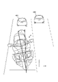
- FIG. 2 is a diagram of a preceding vehicle and a vehicle on the side of the preceding vehicle photographed by an imaging unit;
- the figure which shows the meter panel of a vehicle The figure which shows an example of the process which the control apparatus of a vehicle performs.
- FIG. 1 is a right side view of a straddle-type vehicle 1 according to an embodiment of the present invention
- FIG. 2 is a front view of the straddle-type vehicle 1. As shown in FIG. 1
- the straddle-type vehicle 1 is a tourer-type motorcycle suitable for long-distance travel, but the present invention is applicable to various straddle-type vehicles including other types of motorcycles. It can be applied to an electric vehicle using a motor as a drive source as well as a vehicle using a motor as a drive source.
- the saddle-ride type vehicle 1 may be referred to as the vehicle 1 hereinafter.
- the vehicle 1 has a power unit 2 between the front wheels FW and the rear wheels RW.
- the power unit 2 includes a horizontally opposed six-cylinder engine 21 and a transmission 22 .
- the driving force of the transmission 22 is transmitted to the rear wheels RW via a drive shaft (not shown) to rotate the rear wheels RW.
- the power unit 2 is supported by the body frame 3.
- the body frame 3 includes a pair of left and right main frames 31 extending in the X direction.
- a fuel tank 5 and an air cleaner box (not shown) are arranged above the main frame 31 .
- a meter panel MP is provided in front of the fuel tank 5 to display various information to the rider.
- a head pipe 32 that rotatably supports a steering shaft (not shown) rotated by the handle 8 is provided at the front end of the main frame 31 .
- a pair of left and right pivot plates 33 are provided at the rear end of the main frame 31 .
- a lower end portion of the pivot plate 33 and a front end portion of the main frame 31 are connected by a pair of left and right lower arms (not shown), and the power unit 2 is supported by the main frame 31 and the lower arms.
- a pair of left and right seat rails (not shown) extending rearward are provided at the rear end of the main frame 31.
- the seat rails are a seat 4a on which a rider sits, a seat 4b on which a fellow passenger sits, and a rear trunk. 7b etc. are supported.
- the pivot plate 33 swingably supports the front end of a rear swing arm (not shown) extending in the front-rear direction.
- the rear swing arm is vertically swingable, and the rear end supports the rear wheel RW.
- An exhaust muffler 6 that muffles exhaust noise from the engine 21 extends in the X direction below the rear wheel RW.
- Left and right saddlebags 7a are provided on the upper side of the rear wheel RW.
- a front suspension mechanism 9 that supports the front wheels FW is configured at the front end of the main frame 31 .
- the front suspension mechanism 9 includes an upper link 91 , a lower link 92 , a fork support 93 , a cushion unit 94 and a pair of left and right front forks 95 .
- the upper link 91 and the lower link 92 are arranged at the front end of the main frame 31 with a vertical gap therebetween. Rear ends of the upper link 91 and the lower link 92 are connected to the front end of the main frame 31 so as to be swingable. Front ends of the upper link 91 and the lower link 92 are pivotably connected to a fork support 93 .
- the upper link 91 and the lower link 92 each extend in the front-rear direction and are arranged substantially in parallel.
- the cushion unit 94 has a structure in which a shock absorber is inserted through a coil spring, and its upper end is supported by the main frame 31 so as to be swingable. A lower end portion of the cushion unit 94 is swingably supported by the lower link 92 .
- the fork support 93 is cylindrical and tilts backward.
- the front end of the upper link 21 is rotatably connected to the upper front portion of the fork support 93 .
- a front end portion of the lower link 92 is rotatably connected to the lower rear portion of the fork support 93 .
- a steering shaft 96 is rotatably supported on the fork support 93 about its axis.
- the steering shaft 96 has a shaft portion (not shown) through which the fork support 93 is inserted.
- a bridge (not shown) is provided at the lower end of the steering shaft 96, and a pair of left and right front forks 95 are supported by this bridge.
- the front wheel FW is rotatably supported by the front fork 95 .
- the upper end of the steering shaft 96 is connected via a link 97 to a steering shaft (not shown) rotated by the handle 8 . Steering of the steering wheel 8 rotates the steering shaft 96 to steer the front wheels FW.
- An upper portion of the front wheel FW is covered with a fender 10 , and the fender 10 is supported by front forks 95 .
- the vehicle 1 includes a brake device 19F that brakes the front wheels FW and a brake device 19F that brakes the rear wheels RW.
- the brake devices 19F, 19R are, for example, disc brakes.
- a headlight unit 11 that emits light in front of the vehicle 1 is arranged in the front part of the vehicle 1 .
- the headlight unit 11 of the present embodiment is a twin-lens type headlight unit that includes a right light irradiation section 11R and a left light irradiation section 11L symmetrically.
- a single-lens type headlight unit, a three-lens type headlight unit, or a left-right asymmetric binocular type headlight unit can also be employed.
- the front part of the vehicle 1 is covered with a front cover 12, and the front side part of the vehicle 1 is covered with a pair of left and right side covers 14.
- - ⁇ A screen 13 is arranged above the front cover 12 .
- the screen 13 is a windshield that reduces the wind pressure applied to the rider during running, and is made of, for example, a transparent resin member.
- a pair of left and right side mirror units 15 are arranged on the sides of the front cover 12 .
- a side mirror (not shown) is supported by the side mirror unit 15 so that the rider can visually recognize the rear.
- the front cover 12 includes cowl members 121-123, and the cowl members 121-123 constitute a front cowl.
- the cowl member 121 extends in the Y direction to constitute the main body of the front cover 12 , and the cowl member 122 constitutes the upper portion of the cowl member 121 .
- the cowl member 123 is spaced downward from the cowl member 121 .
- An opening for exposing the headlight unit 11 is formed between the cowl members 121 and 123 and between the pair of left and right side covers 14.
- the upper edge of this opening is defined by the cowl member 121 and the lower edge. is defined by the cowl member 123 , and the left and right side edges are defined by the side covers 14 .
- a detection unit 105 for detecting the situation in front of the vehicle 1 is arranged behind the front cover 12 .
- the detection unit 105 is a radar (for example, a millimeter wave radar), but may be another type of sensor that can detect the front through the front cover 12 .
- the meter panel MP can be displayed to call the rider's attention, or the brake devices 19F and 19R can be automatically operated.
- the vehicle 1 can be decelerated.
- the imaging unit 102 includes an imaging device such as a CCD image sensor or a CMOS image sensor and an optical system such as a lens, and captures an image in front of the vehicle 1 .
- the imaging unit 102 is arranged behind the upper portion of the front cowl 12 .
- An opening 12a is formed through the front cowl 12, and the imaging unit 102 captures an image in front of the vehicle 1 through the opening 12a.
- the arrangement of the imaging unit 102 and the radar 105 is an example.
- the imaging unit 102 and the radar 105 may be arranged at other positions such as under the jaw of the headlight unit 11 or inside.
- the radar 105 is arranged behind the front cowl 12. Due to the existence of the front cowl 12, the presence of the detection unit 105 can be made inconspicuous when viewed from the front of the vehicle 1, and deterioration of the appearance of the vehicle 1 can be avoided. A portion of the front cowl 12 located in front of the radar 105 is made of a material such as resin that allows electromagnetic waves to pass therethrough.
- the imaging unit 102 and the radar 105 are arranged in the center of the front cowl 12 in the Y direction when viewed from the front of the vehicle.
- By arranging the imaging unit 102 and the radar 105 in the center of the vehicle 1 in the Y direction it is possible to obtain a wider imaging range and a wider detection range on the left and right sides in front of the vehicle 1, so that the situation in front of the vehicle 1 can be seen more clearly. It can be detected without oversight.
- one imaging unit 102 and one radar 105 can uniformly monitor the front of the vehicle 1 on the left and right sides, instead of providing a plurality of imaging units 102 and radars 105, a configuration in which one imaging unit 102 and one radar 105 are provided, It is particularly advantageous.
- FIG. 3 is a block diagram of the control device 100 of the vehicle 1, and shows only the necessary configuration in relation to the description that will be given later.
- the control unit 101 is a control device (information processing device) including a processor represented by a CPU, a storage device such as a semiconductor memory, an input/output interface or a communication interface with an external device, and the like.
- the storage device stores programs executed by the processor, data used for processing by the processor, and the like.
- the control unit 101 may include multiple processors, storage devices, interfaces, and the like. It should be noted that the number of control units 101 and their assigned functions can be appropriately designed.
- the imaging unit 102 is an imaging unit including one or more imaging devices, for example, a camera, that captures an image in front of the vehicle 1 .
- the imaging unit 102 is arranged in front of the vehicle 1 and near the center in the left-right direction.
- the imaging unit 102 may include one or more imaging devices that capture behind the vehicle 1 .
- the inertial measurement unit (IMU) 103 is an inertial sensor unit that detects the behavior of the vehicle 1, and is arranged near the center of gravity of the vehicle 1, for example.
- the IMU 103 includes an acceleration sensor that detects acceleration in the longitudinal direction, the lateral direction, and the vertical direction of the vehicle 1, and angular velocity sensors that detect the angular velocity in the roll direction, the pitch direction, and the yaw direction of the vehicle 1. including.
- a vehicle speed sensor 104 detects the vehicle speed of the vehicle 1 .
- the vehicle speed sensor 104 is a sensor that is supported by, for example, the front fork 95 and detects the amount of rotation of the front wheels FW.
- the detection unit 105 includes a detection device including a ranging sensor such as LIDAR (Light Detection and Ranging).
- the brake actuator 106 is a device that operates the brake devices 19F and 19R, such as a hydraulic device.
- the meter panel MP urges the rider to avoid the collision or notifies information for assisting the rider in avoiding the collision.
- the control unit 101 displays on the meter panel MP a notification for avoiding contact between the vehicle and an object ahead.
- the notification for contact avoidance is displayed as an image on the meter panel MP, but it may be a lighting or blinking of a lamp, or an audio notification.
- the notification by voice may be controlled to output voice through wireless communication from a speaker provided on the rider's helmet. Further, the notification by the meter panel MP may be combined with these notifications.
- Control of the vehicle 1 according to the present embodiment will be described with reference to FIG.
- a rider on the vehicle 1 must take an avoidance action to avoid contact with an object (for example, the preceding vehicle 401 in FIG. 4) that may collide with the object in front of the vehicle while the vehicle is running.
- Avoidance actions include avoidance action by braking and avoidance action by turning. Depending on the positional relationship between the forward object and the vehicle 1, avoidance by turning may be more suitable.
- the rider in order for the rider to make a decision to avoid the vehicle by turning, the rider must quickly determine, for example, whether or not there is a space to avoid. Therefore, in this embodiment, when there is a possibility of collision with an object ahead, the control unit 101 displays a notification on the meter panel MP to provide the rider with information on the avoidable space.
- a side vehicle 402 is running to the right of the preceding vehicle 401. Further, an obstacle such as a curb or a guardrail may be positioned to the left of the preceding vehicle 401 . Therefore, the control unit 101 recognizes the distance in the width direction from the preceding vehicle 401 to an area 406 such as a sidewalk bounded by a guardrail, a curb, or the like, as a travelable width 403 . Note that the control unit 101 may recognize the distance from the preceding vehicle 401 to the roadway outside line 405, which does not include the shoulder portion of the road, as the travelable width. The control unit 101 also recognizes the distance in the width direction from the preceding vehicle 401 to the side vehicle 402 as the travelable width 404 .
- control unit 101 may recognize the distance from the preceding vehicle 401 to the center line as the travelable width.
- travelable width 403 on the left side of the preceding vehicle 401 the preceding vehicle 401, structures on the road such as guardrails and curbs located on the left side of the preceding vehicle 401, and side vehicles and pedestrians on the left side.
- the travelable width 403 may be the distance in the width direction to the traffic participant.
- the vehicle 1 has a first object located in front of the vehicle 1 with a possibility of collision and an The distance between the vehicle and the second object is determined as the travelable width.
- a first object includes a traffic participant, such as the preceding vehicle 401 .
- the second object may be any object that can be recognized by the imaging unit 102, including traffic participants, structures on the road, and white lines such as the center line and the roadway outside line.
- the vehicle 1 may be tilted (banked or rolled) relative to the preceding vehicle 401 .
- the vehicle 1 is banked at an angle ⁇ with respect to the preceding vehicle 401 as shown in FIG. and the relative bank angle (roll angle) .theta.
- control unit 101 can specify the bank angle ⁇ based on the image acquired from the imaging unit 102 of the vehicle 1.
- the control unit 101 may determine the bank angle ⁇ based on the output of the IMU 103 or the combination of the output of the IMU and the image acquired from the imaging unit 102 .
- control unit 101 when the control unit 101 detects an avoidable space on the side of the preceding vehicle 401 based on an image captured by the image capturing unit 102, the control unit 101 performs image recognition on the captured image to obtain a Identify the area of the preceding vehicle 401 that is included. For example, as shown in FIG. 6, rectangular frames 601 and 602 surrounding a preceding vehicle 401 and a side vehicle 402, respectively, are specified.
- the control unit 101 determines whether the preceding vehicle 401 side travelable width is determined.
- the bank angle ⁇ may be determined from the inclination of the vehicle 1 from the road.
- control unit 101 similarly determines the left travelable width of the preceding vehicle 401 . That is, the control unit 101 object-recognizes the preceding vehicle 401, road structures such as guardrails and curbs located to the left of the preceding vehicle 401, and traffic participants such as side vehicles and pedestrians on the left side. Next, based on the width direction length of the travelable width from the preceding vehicle 401 to the object on the left side of the preceding vehicle 401 and the relative inclination of the vehicle 1 and the preceding vehicle 401, the traveling distance of the left side of the preceding vehicle 401 is determined. Determine the available width.
- the control unit 101 When it is determined that there is an evasable space for the vehicle 1 on the right or left side of the preceding vehicle 401, the control unit 101 notifies the rider to avoid turning.
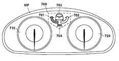
- the meter panel MP of FIG. 7 includes a notification area 700 for notifying the above-described turning avoidance in addition to notification areas such as a speedometer 710 and a tachometer 720 .
- the meter panel MP may include an area for displaying the indicated direction of the direction indicator, the remaining fuel amount gauge, the water temperature gauge, or the like.
- the meter panel MP may be entirely composed of a display unit such as a liquid crystal display or an organic EL display, or may be a combination of analog gauges and a display unit.
- the notification area 700 is provided in the central portion of the meter panel MP, which is easily visible to the rider.
- the notification area 700 includes an indicator 701 prompting to avoid turning left and an indicator 702 prompting to avoid turning right.
- the notification area 700 also displays an icon 703 indicating the preceding vehicle so that the user can intuitively grasp the turning direction from the indicators 701 and 702 .
- the notification area 700 may also display an indicator 704 that indicates the possible travel width. For example, in the example of FIG. 7, the control unit 101 lights the indicator 701 to prompt the left turn. In addition, the indicator 704 notifies that the left travelable width of the preceding vehicle is 3 m. These notifications allow the rider to quickly determine whether or not to avoid turning.
- the notification area 700 is set to OFF when, for example, the control unit 101 determines that it is not necessary to issue a notification prompting to avoid turning, and the indicators 701 and 702, the icon 703, and the indicator 704 are displayed. not. Further, for example, when the control unit 101 determines to issue a notification prompting to avoid turning left, the indicator 701 and the icon 703 are displayed. Note that, in one example, even when the control unit 101 determines that it is not necessary to issue a notification to urge avoidance of turning, even if at least one element of the notification area 700 such as the icon 703 is set to ON. good.
- the indicators 701 and 702 will be described as being set to either lit (ON) or extinguished (OFF).
- the color, flashing pattern, and the like may be arbitrarily set according to the travelable width and the distance to the preceding vehicle. For example, a blue indicator is displayed when the available width of the vehicle ahead is 5m or more, a yellow indicator is displayed when the width is less than 5m and 3m or more, and an orange indicator is displayed when the width is less than 3m and 2m or more. may be displayed. This allows the rider to intuitively grasp the travelable width.
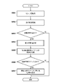
- FIG. 8 is a flowchart relating to notification processing of contact avoidance with an object in front executed by the control unit 101 .
- Each process described below is realized by the processor reading and executing a program stored in the storage device in the control unit 101 .
- the traffic rules for vehicles on the road are assumed to be left-hand traffic. Further, each process described below is periodically and repeatedly executed by the control unit 101 .
- avoidance by turning includes avoidance of contact with an object in front, which involves movement in the width direction of the vehicle 1 .
- avoidance by turning includes movement to a space on the side of an object in front by steering the steering wheel 8 by the rider or tilting the body of the vehicle 1 by the rider.
- the control unit 101 may control the brake actuator 106 based on the length in the direction intersecting the traveling direction of the vehicle 1 of the space to the side of the object in front to provide driving assistance.
- step S801 the control unit 101 acquires sensor values of various sensors.
- the control unit 101 acquires detection results of the imaging unit 102, IMU 103, vehicle speed sensor 104, and radar 105 as sensor values of various sensors.
- control unit 101 recognizes the surrounding conditions of the own vehicle.
- the control unit 101 performs front detection to recognize the existence of the preceding vehicle 401 and the vehicle 402 based on the sensor values acquired from the imaging unit 102 and the radar 105 in S801. For example, in front detection, as shown in FIG. 6, an image including preceding vehicle 401 and vehicle 402 is acquired, and frames 601 and 602 corresponding to preceding vehicle 401 and vehicle 402 are specified. Further, for example, the control unit 101 recognizes the speed difference with the preceding vehicle 401 and the inter-vehicle distance 407 based on the sensor values acquired in S801. The control unit 101 also recognizes the length of the space on the side of the preceding vehicle 401 in the direction intersecting the traveling direction of the vehicle 1, like the distance d in FIG.
- control unit 101 performs bank angle detection to specify the bank angle based on the sensor value acquired from the imaging unit 102 in S801.
- control unit 101 may perform bank angle detection for specifying the bank angle based on the sensor value acquired from the IMU 103 in S801, or combine the sensor values acquired from the imaging unit 102 and the IMU 103 to determine the bank angle.
- Bank angle detection for specifying the bank angle may be performed, or bank angle detection for specifying the bank angle based on an image acquired from the imaging unit 102 may be performed.
- the bank angle identified based on the image obtained from the imaging unit 102 and the bank angle identified based on the sensor value obtained from the IMU 103. may be used as the bank angle.
- the bank angle is specified based on the image acquired from the imaging unit 102, and when the vehicle 1 is traveling in a medium speed range and a high speed range, the bank angle is determined from the IMU 103.
- the bank angle may be specified based on the acquired sensor value.
- a portion of the leading vehicle 401 such as a license plate is image-recognized as a marker based on the image, and the leading vehicle 401 is detected based on the degree of rotation of the marker. may specify a bank angle relative to .
- a road structure such as a road sign or guide sign is used as a marker for image recognition, and the A bank angle relative to the object may be determined based on the rotation of the marker.
- control unit 101 performs speed detection to specify the running speed based on the sensor value acquired from the vehicle speed sensor 104 in S801.
- control unit 101 may execute the surrounding situation recognition in S802 using only the detection result of the imaging unit 102, only using the detection result of the radar 105, or both. may be executed using the detection result of Also, the control unit 101 may perform the surrounding situation recognition in S802 based on other information. For example, vehicle-to-vehicle communication or road-to-vehicle communication may be performed by a communication device connected to the control unit 101 to acquire the speed information of the preceding vehicle 401 and the vehicle-to-vehicle distance 407 .
- the control unit 101 proceeds to S804 if there is a possibility that the vehicle 1 will come into contact with an object in front of it, and ends the flowchart if there is no possibility of contact. For example, based on the inter-vehicle distance 407 and the speed difference between the vehicle 1 and the preceding vehicle 401, the control unit 101 determines whether the vehicle 1 and the preceding vehicle 401 can contact each other within a predetermined period if the current state continues. to confirm. In the example of FIG. 4, when the speed of the vehicle 1 is greater than that of the preceding vehicle 401 and the current speed difference causes the vehicle 1 to contact the preceding vehicle 401 within a predetermined period of time, the control unit 101 can contact the preceding vehicle. determine that it is viable. In the following description, it is assumed that FIG. 4 shows a state in which there is a possibility of contact between the vehicle 1 and the preceding vehicle 401 .
- the recognition of the surrounding situation in S802 and the determination of the possibility of contact in S803 may be performed using the detection results of the same detection device, or may be performed using the detection results of different detection devices.
- both determinations may be made using the detection results of the imaging unit 102 and the radar 105, or the determination in S802 may be made using the detection results of the imaging unit 102, and the determination in S803 may be made using the detection results of the radar 105. may be used.
- control unit 101 uses the distance d between the preceding vehicle 401 and an object on its side measured in S802 as a reference distance, and corrects the reference distance based on the bank angle ? Determine the lateral travelable width of the
- the control unit 101 determines whether or not the absolute value of the bank angle ⁇ is greater than a predetermined bank angle threshold. For example, the control unit 101 acquires the detection result of the angular velocity sensor included in the IMU 103 in the roll direction (bank direction). The acquired detection result is saved in the storage device of the control unit 101 . The storage device stores the detection results for a plurality of times in chronological order. The roll direction angle is obtained by integrating the roll direction detection results output by the IMU 103 . When the absolute value of this integrated value is larger than a preset threshold value, it can be determined that the absolute value of the bank angle ⁇ is larger than the bank angle threshold value.
- control unit 101 advances the process to S903, identifies the distance d measured in S802 as the travelable width, and processes S804. exit.
- the control unit 101 proceeds to S902 and corrects the distance d measured in S802 based on the bank angle ⁇ .
- the travelable width is specified and the processing of S804 is terminated.
- control unit 101 includes a storage device such as a HDD (Hard Disk Drive), and refers to a table that associates the distance d, the bank angle ⁇ , and the travelable width W stored in the storage device. A possible width W may be specified.
- control unit 101 refers to this table with the distance d and the bank angle ⁇ measured in S802, and specifies the corresponding travelable width W.
- the control unit 101 determines whether or not there is an avoidable space for avoiding a collision with the preceding vehicle 401 by turning. For example, the control unit 101 may determine whether or not there is an evasable space based on the information about the travelable width W specified in S804 and the information about the vehicle width of the vehicle 1 . Specifically, the control unit 101 stores information on the required width required for the vehicle 1 to pass in the storage device. Then, when the travelable width 403 or the travelable width 404 is larger than the required width, it is determined that there is an avoidable space to avoid by turning. For example, the required width may be 1.5 to 3.0 times the width of the vehicle 1 .
- the control unit 101 determines that there is an evasable space for the vehicle 1 . On the other hand, if both the travelable widths 403 and 404 are smaller than the required width, it is determined that there is no avoidable space.
- control unit 101 advances to S807 if there is an avoidable space based on the determination in S805, and ends the flowchart if there is no avoidable space. In the example of FIG. 4, it is determined that there is an evasable space on the left side of the preceding vehicle 401, and the process proceeds to S807.
- the control unit 101 causes notification of information regarding the avoidable space.
- the control unit 101 notifies the rider of the avoidable space information by displaying the avoidable space information in the notification area 700 of the meter panel MP. After that, the flowchart ends.
- the IMU 103 may have a large measurement error in the low speed range. When such an IMU 103 is used in a low speed range, it may be determined that there is no avoidable space even though there is an avoidable space in which the vehicle can actually travel, or there is actually no avoidable space in which the vehicle can travel. However, it may be determined that there is an evasable space in which the vehicle can travel, and the vehicle may be urged to avoid turning.
- the control unit 101 determines the bank angle by correcting the sensor value obtained from the IMU 103 when the vehicle 1 is traveling in a low speed range. Details of the processing of S804 executed by the control unit 101 according to the present embodiment will be described with reference to FIG. Note that the processing of S1003 to S1005 is the same as the processing of S901 to S903, so description thereof will be omitted.
- the control unit 101 determines whether the traveling speed of the vehicle 1 is less than the speed threshold based on the sensor value obtained from the vehicle speed sensor in S802. If the running speed of the vehicle 1 is equal to or higher than the speed threshold, the control unit 101 determines that the error in the bank angle acquired from the IMU 103 is small because the vehicle 1 is not running in a low speed range, and advances the process to S1006. .
- the control unit 101 advances the process to S1002 and identifies the bank angle based on the output of the IMU 103 and the output of a sensor different from the IMU 103. This is because noise in the output of the IMU 103 increases as the traveling speed of the vehicle 1 decreases. Therefore, the bank angle of the vehicle 1 with respect to the road surface may be specified by measuring the distance to the road surface based on the output of a distance measuring sensor such as ARAS (Advanced Rider Assistance System).
- ARAS Advanced Rider Assistance System
- the road surface is banked in the detected direction in the width direction of the vehicle 1, and the bank angle can be specified based on the detected distance to the road surface and the installation position of the ranging sensor. can.
- the bank angle is the average value of the bank angle specified based on the output of the IMU 103 and the bank angle specified based on the output of the ranging sensor.
- the bank angle measurement quality can be improved.
- the output of IMU 103 may be corrected based on the output of the temperature sensor.
- S1002 is described assuming that the bank angle is specified based on the output of a sensor different from the IMU 103 in order to suppress the noise of the IMU 103 in the low speed range.
- the processing may correct the output of the IMU 103 .
- the control unit 101 may continuously acquire the output of the IMU 103 and specify the average value (moving average) of the acquired output values as the bank angle. Thereby, high-frequency noise contained in the IMU 103 can be reduced.
- the control unit 101 sets the fixed value to the bank angle. It can be specified as For example, when the vehicle 1 is traveling in a low speed range, if the output value of the IMU 103 indicates that the bank angle is -15 degrees or less or 15 degrees or more, the control unit 101 determines that the bank angle is 15 degrees. degree. Further, when the vehicle 1 is traveling in a low speed range, the control unit 101 may determine that the bank angle is 0 degrees when the bank angle is -5 to 5 degrees or less.
- bank angle specifications may be combined arbitrarily.
- the output of the IMU 103 is continuously acquired, and the fixed value is specified as the bank angle as described above according to the range of the average value (moving average) of the acquired output values. good too.
- the control unit 101 advances the process to S1006 and identifies the bank angle based on the output of the IMU103.
- the bank angle can be identified at high speed with a reduced amount of calculation.
- ⁇ Other embodiments> the process of specifying avoidable space on the side of the object when there is a possibility of contact with the object in front of the vehicle 1 has been described.
- an avoidable space on the side of an object behind the vehicle 1 may be identified. For example, a rear vehicle approaching the vehicle 1 from the rear of the vehicle 1 may be notified of whether or not to turn left or right to avoid turning by specifying an evasable space on the side.
- control unit 101 identifies an avoidable space on the side of an object in front of the vehicle 1 when there is a possibility of contact, and controls the brake actuator 106. Turning avoidance can be done automatically with .
- the configuration of the notification area 700 is an example, and the display image may be changed or omitted as appropriate.
- the indicators 701 and 702 may be other symbols or letters instead of arrows.
- the notification regarding the avoidable space may be suppressed.
- the control unit 101 may cause the meter panel MP to display a notification prompting avoidance of contact with the preceding vehicle 401 by braking.
- the control unit 101 may display on the meter panel MP that contact with the preceding vehicle 401 can be avoided by braking or turning.
- the saddle-ride type vehicle (1) of the above embodiment is forward detection means (102, 105) for detecting an object positioned in front of the saddle-ride type vehicle; bank angle detection means (103) for detecting the bank angle of the straddle-type vehicle; Identifying means ( 101, S804) and Prepare.
- the notification means are indicators (701, 702) that indicate whether the saddle-type vehicle should turn right or left to travel in the space.
- the rider can intuitively grasp the space on the side of the object in which the rider should travel.
- said notification means is an indicator (704) corresponding to said distance of said two objects.
- the rider can accurately grasp the space on the side of the object in which the rider should travel.
- the forward detection means detects a reference distance corresponding to the distance between the two detected objects
- the identifying means identifies the distance by correcting the reference distance based on the bank angle (S902).
- the specifying means divides the reference distance detected by the forward detection means by a cosine value based on the bank angle detected by the bank angle detection means, and calculates the distance between the two objects. It is characterized by specifying as
- the forward detection means detects a reference distance (603) corresponding to the distance between the two detected objects,
- the identifying means identifies the distance by referring to a table in which the reference distance, the bank angle, and the distance are associated.
- the specifying means specifies the reference distance as the distance.
- the vehicle further comprises speed detection means (104) for detecting the traveling speed of the saddle-ride type vehicle, the bank angle detection means includes at least one of an imaging unit (102) and an inertial sensor (103); When the running speed detected by the speed detection means is equal to or higher than a predetermined speed threshold, the bank angle detection means detects the bank angle based on the output of at least one of the imaging unit and the inertial sensor. decide.
- the bank angle detection means determines the bank angle as a fixed value corresponding to the range of the output values of the inertial sensor.
- the bank angle detection means determines the bank angle based on a moving average of the output values of the inertial sensor.
- the bank angle detection means determines the bank angle based on the output value of the inertia sensor and the output value of a sensor different from the inertia sensor.
- the forward detection means detects an object by performing image recognition on an image acquired by an imaging device arranged on the saddle type vehicle.
- the information processing device provided in the saddle-ride type vehicle of the present embodiment includes: a first acquisition means for acquiring a detection result of an object positioned in front of the straddle-type vehicle; a second acquiring means for acquiring a detection result of the bank angle of the straddle-type vehicle; Based on the detection results obtained by the first obtaining means and the second obtaining means, a distance between the two objects obtained by the first obtaining means in a direction intersecting the traveling direction of the straddle-type vehicle is specified. a specific means to Prepare.
- the information processing method executed by the straddle-type vehicle of this embodiment includes: a forward detection step of detecting an object positioned in front of the straddle-type vehicle; a bank angle detection step of detecting a bank angle of the straddle-type vehicle; a specifying step of specifying a distance in a direction intersecting the traveling direction of the saddle-ride type vehicle between the two objects detected in the forward detecting step based on the detection results in the forward detecting step and the bank angle detecting step; , including.
Landscapes
- Physics & Mathematics (AREA)
- General Physics & Mathematics (AREA)
- Traffic Control Systems (AREA)
Priority Applications (3)
| Application Number | Priority Date | Filing Date | Title |
|---|---|---|---|
| JP2022579241A JP7502479B2 (ja) | 2021-02-04 | 2021-02-04 | 鞍乗り型車両、情報処理装置、情報処理方法 |
| DE112021007005.3T DE112021007005T5 (de) | 2021-02-04 | 2021-02-04 | Grätschsitzfahrzeug, informationsverarbeitungsvorrichtung und informationsverarbeitungsverfahren |
| PCT/JP2021/004120 WO2022168235A1 (ja) | 2021-02-04 | 2021-02-04 | 鞍乗り型車両、情報処理装置、情報処理方法 |
Applications Claiming Priority (1)
| Application Number | Priority Date | Filing Date | Title |
|---|---|---|---|
| PCT/JP2021/004120 WO2022168235A1 (ja) | 2021-02-04 | 2021-02-04 | 鞍乗り型車両、情報処理装置、情報処理方法 |
Publications (1)
| Publication Number | Publication Date |
|---|---|
| WO2022168235A1 true WO2022168235A1 (ja) | 2022-08-11 |
Family
ID=82740985
Family Applications (1)
| Application Number | Title | Priority Date | Filing Date |
|---|---|---|---|
| PCT/JP2021/004120 Ceased WO2022168235A1 (ja) | 2021-02-04 | 2021-02-04 | 鞍乗り型車両、情報処理装置、情報処理方法 |
Country Status (3)
| Country | Link |
|---|---|
| JP (1) | JP7502479B2 (https=) |
| DE (1) | DE112021007005T5 (https=) |
| WO (1) | WO2022168235A1 (https=) |
Cited By (3)
| Publication number | Priority date | Publication date | Assignee | Title |
|---|---|---|---|---|
| JPWO2022168236A1 (https=) * | 2021-02-04 | 2022-08-11 | ||
| WO2024213952A1 (ja) * | 2023-04-12 | 2024-10-17 | ロベルト•ボッシュ•ゲゼルシャフト•ミト•ベシュレンクテル•ハフツング | 制御装置及び制御方法 |
| WO2025158549A1 (ja) * | 2024-01-24 | 2025-07-31 | Astemo株式会社 | 車両制御装置 |
Citations (6)
| Publication number | Priority date | Publication date | Assignee | Title |
|---|---|---|---|---|
| JP2004114907A (ja) * | 2002-09-27 | 2004-04-15 | Fuji Photo Film Co Ltd | 車幅車高検出警告装置 |
| JP2005326963A (ja) * | 2004-05-12 | 2005-11-24 | Fujitsu Ten Ltd | 運転支援装置 |
| JP2008030541A (ja) * | 2006-07-26 | 2008-02-14 | Toyota Motor Corp | 車両用運転支援装置、及び、車両用表示装置 |
| JP2018118716A (ja) * | 2017-01-25 | 2018-08-02 | ハーレー−ダビッドソン・モーター・カンパニー・グループ・エルエルシー | 自律制動を有する鞍乗り型車両及び自律制動を動作させる方法 |
| JP2020500784A (ja) * | 2016-12-14 | 2020-01-16 | ロベルト・ボッシュ・ゲゼルシャフト・ミト・ベシュレンクテル・ハフツングRobert Bosch Gmbh | 自動二輪車の速度を自動的に調整するための方法 |
| WO2020116265A1 (ja) * | 2018-12-05 | 2020-06-11 | 日立オートモティブシステムズ株式会社 | 車両制御装置 |
Family Cites Families (1)
| Publication number | Priority date | Publication date | Assignee | Title |
|---|---|---|---|---|
| JPH0690760B2 (ja) | 1991-01-23 | 1994-11-14 | 株式会社カンセイ | 先行車両位置検出装置 |
-
2021
- 2021-02-04 DE DE112021007005.3T patent/DE112021007005T5/de active Pending
- 2021-02-04 WO PCT/JP2021/004120 patent/WO2022168235A1/ja not_active Ceased
- 2021-02-04 JP JP2022579241A patent/JP7502479B2/ja active Active
Patent Citations (6)
| Publication number | Priority date | Publication date | Assignee | Title |
|---|---|---|---|---|
| JP2004114907A (ja) * | 2002-09-27 | 2004-04-15 | Fuji Photo Film Co Ltd | 車幅車高検出警告装置 |
| JP2005326963A (ja) * | 2004-05-12 | 2005-11-24 | Fujitsu Ten Ltd | 運転支援装置 |
| JP2008030541A (ja) * | 2006-07-26 | 2008-02-14 | Toyota Motor Corp | 車両用運転支援装置、及び、車両用表示装置 |
| JP2020500784A (ja) * | 2016-12-14 | 2020-01-16 | ロベルト・ボッシュ・ゲゼルシャフト・ミト・ベシュレンクテル・ハフツングRobert Bosch Gmbh | 自動二輪車の速度を自動的に調整するための方法 |
| JP2018118716A (ja) * | 2017-01-25 | 2018-08-02 | ハーレー−ダビッドソン・モーター・カンパニー・グループ・エルエルシー | 自律制動を有する鞍乗り型車両及び自律制動を動作させる方法 |
| WO2020116265A1 (ja) * | 2018-12-05 | 2020-06-11 | 日立オートモティブシステムズ株式会社 | 車両制御装置 |
Cited By (4)
| Publication number | Priority date | Publication date | Assignee | Title |
|---|---|---|---|---|
| JPWO2022168236A1 (https=) * | 2021-02-04 | 2022-08-11 | ||
| JP7556986B2 (ja) | 2021-02-04 | 2024-09-27 | 本田技研工業株式会社 | 鞍乗型車両、その制御方法、制御装置、及びプログラム |
| WO2024213952A1 (ja) * | 2023-04-12 | 2024-10-17 | ロベルト•ボッシュ•ゲゼルシャフト•ミト•ベシュレンクテル•ハフツング | 制御装置及び制御方法 |
| WO2025158549A1 (ja) * | 2024-01-24 | 2025-07-31 | Astemo株式会社 | 車両制御装置 |
Also Published As
| Publication number | Publication date |
|---|---|
| DE112021007005T5 (de) | 2023-11-30 |
| JP7502479B2 (ja) | 2024-06-18 |
| JPWO2022168235A1 (https=) | 2022-08-11 |
Similar Documents
| Publication | Publication Date | Title |
|---|---|---|
| JP6516089B2 (ja) | 車両情報投影システム及び車両情報投影方法 | |
| JP7502479B2 (ja) | 鞍乗り型車両、情報処理装置、情報処理方法 | |
| US12545348B2 (en) | Straddle type vehicle, method for controlling the same, control apparatus, and storage medium | |
| JPWO2019111139A1 (ja) | モータサイクルの挙動を制御する制御装置及び制御方法 | |
| WO2021060357A1 (ja) | Fcw制御装置を備えたリーン車両 | |
| CN113443051B (zh) | 跨骑型车辆以及控制装置 | |
| WO2021111224A1 (ja) | ライダー支援システム、及び、ライダー支援システムの制御方法 | |
| JP2022122534A (ja) | 車両、車両の制御方法、及びコンピュータプログラム | |
| JPWO2019038918A1 (ja) | 走行制御装置、および車両 | |
| JP2009166764A (ja) | 車両の接触回避支援装置 | |
| JP2021152780A (ja) | 鞍乗型車両及び制御装置 | |
| JP7145179B2 (ja) | 鞍乗型車両及び制御装置 | |
| JP2022131239A (ja) | 車両、車両の制御方法、及びコンピュータプログラム | |
| JP7549529B2 (ja) | 制御装置、制御方法及び車両 | |
| WO2022195997A1 (ja) | 鞍乗型車両 | |
| JP5016502B2 (ja) | 車両の接触回避支援装置 | |
| JP2020166479A (ja) | 運転支援装置 | |
| JP7725275B2 (ja) | システム、車両、携帯端末、及びそれらの方法 | |
| JP7642789B2 (ja) | 車載装置、車両、情報処理方法、およびプログラム | |
| JP7730872B2 (ja) | 鞍乗り型車両 | |
| JP6295677B2 (ja) | 運転診断装置、保険料算定装置、運転診断方法および保険料算定方法 | |
| US20220203963A1 (en) | Estimation device and straddle-type vehicle | |
| JP2019121071A (ja) | 運転支援装置 | |
| WO2025017914A1 (ja) | 情報処理装置、情報処理方法、及びプログラム | |
| JP2026059158A (ja) | 安全運転補助装置および安全運転補助方法 |
Legal Events
| Date | Code | Title | Description |
|---|---|---|---|
| 121 | Ep: the epo has been informed by wipo that ep was designated in this application |
Ref document number: 21924631 Country of ref document: EP Kind code of ref document: A1 |
|
| WWE | Wipo information: entry into national phase |
Ref document number: 202317045417 Country of ref document: IN |
|
| ENP | Entry into the national phase |
Ref document number: 2022579241 Country of ref document: JP Kind code of ref document: A |
|
| WWE | Wipo information: entry into national phase |
Ref document number: 112021007005 Country of ref document: DE |
|
| 122 | Ep: pct application non-entry in european phase |
Ref document number: 21924631 Country of ref document: EP Kind code of ref document: A1 |