WO2022162901A1 - 外気処理装置 - Google Patents
外気処理装置 Download PDFInfo
- Publication number
- WO2022162901A1 WO2022162901A1 PCT/JP2021/003358 JP2021003358W WO2022162901A1 WO 2022162901 A1 WO2022162901 A1 WO 2022162901A1 JP 2021003358 W JP2021003358 W JP 2021003358W WO 2022162901 A1 WO2022162901 A1 WO 2022162901A1
- Authority
- WO
- WIPO (PCT)
- Prior art keywords
- outside air
- air
- heat exchanger
- flow path
- cooler
- Prior art date
- Legal status (The legal status is an assumption and is not a legal conclusion. Google has not performed a legal analysis and makes no representation as to the accuracy of the status listed.)
- Ceased
Links
Images



Classifications
-
- F—MECHANICAL ENGINEERING; LIGHTING; HEATING; WEAPONS; BLASTING
- F24—HEATING; RANGES; VENTILATING
- F24F—AIR-CONDITIONING; AIR-HUMIDIFICATION; VENTILATION; USE OF AIR CURRENTS FOR SCREENING
- F24F11/00—Control or safety arrangements
- F24F11/70—Control systems characterised by their outputs; Constructional details thereof
- F24F11/72—Control systems characterised by their outputs; Constructional details thereof for controlling the supply of treated air, e.g. its pressure
-
- F—MECHANICAL ENGINEERING; LIGHTING; HEATING; WEAPONS; BLASTING
- F24—HEATING; RANGES; VENTILATING
- F24F—AIR-CONDITIONING; AIR-HUMIDIFICATION; VENTILATION; USE OF AIR CURRENTS FOR SCREENING
- F24F11/00—Control or safety arrangements
- F24F11/0008—Control or safety arrangements for air-humidification
-
- F—MECHANICAL ENGINEERING; LIGHTING; HEATING; WEAPONS; BLASTING
- F24—HEATING; RANGES; VENTILATING
- F24F—AIR-CONDITIONING; AIR-HUMIDIFICATION; VENTILATION; USE OF AIR CURRENTS FOR SCREENING
- F24F11/00—Control or safety arrangements
- F24F11/62—Control or safety arrangements characterised by the type of control or by internal processing, e.g. using fuzzy logic, adaptive control or estimation of values
- F24F11/63—Electronic processing
- F24F11/65—Electronic processing for selecting an operating mode
-
- F—MECHANICAL ENGINEERING; LIGHTING; HEATING; WEAPONS; BLASTING
- F24—HEATING; RANGES; VENTILATING
- F24F—AIR-CONDITIONING; AIR-HUMIDIFICATION; VENTILATION; USE OF AIR CURRENTS FOR SCREENING
- F24F3/00—Air-conditioning systems in which conditioned primary air is supplied from one or more central stations to distributing units in the rooms or spaces where it may receive secondary treatment; Apparatus specially designed for such systems
- F24F3/12—Air-conditioning systems in which conditioned primary air is supplied from one or more central stations to distributing units in the rooms or spaces where it may receive secondary treatment; Apparatus specially designed for such systems characterised by the treatment of the air otherwise than by heating and cooling
- F24F3/14—Air-conditioning systems in which conditioned primary air is supplied from one or more central stations to distributing units in the rooms or spaces where it may receive secondary treatment; Apparatus specially designed for such systems characterised by the treatment of the air otherwise than by heating and cooling by humidification; by dehumidification
-
- F—MECHANICAL ENGINEERING; LIGHTING; HEATING; WEAPONS; BLASTING
- F24—HEATING; RANGES; VENTILATING
- F24F—AIR-CONDITIONING; AIR-HUMIDIFICATION; VENTILATION; USE OF AIR CURRENTS FOR SCREENING
- F24F3/00—Air-conditioning systems in which conditioned primary air is supplied from one or more central stations to distributing units in the rooms or spaces where it may receive secondary treatment; Apparatus specially designed for such systems
- F24F3/12—Air-conditioning systems in which conditioned primary air is supplied from one or more central stations to distributing units in the rooms or spaces where it may receive secondary treatment; Apparatus specially designed for such systems characterised by the treatment of the air otherwise than by heating and cooling
- F24F3/14—Air-conditioning systems in which conditioned primary air is supplied from one or more central stations to distributing units in the rooms or spaces where it may receive secondary treatment; Apparatus specially designed for such systems characterised by the treatment of the air otherwise than by heating and cooling by humidification; by dehumidification
- F24F3/1411—Air-conditioning systems in which conditioned primary air is supplied from one or more central stations to distributing units in the rooms or spaces where it may receive secondary treatment; Apparatus specially designed for such systems characterised by the treatment of the air otherwise than by heating and cooling by humidification; by dehumidification by absorbing or adsorbing water, e.g. using an hygroscopic desiccant
- F24F3/1429—Air-conditioning systems in which conditioned primary air is supplied from one or more central stations to distributing units in the rooms or spaces where it may receive secondary treatment; Apparatus specially designed for such systems characterised by the treatment of the air otherwise than by heating and cooling by humidification; by dehumidification by absorbing or adsorbing water, e.g. using an hygroscopic desiccant alternatively operating a heat exchanger in an absorbing/adsorbing mode and a heat exchanger in a regeneration mode
-
- F—MECHANICAL ENGINEERING; LIGHTING; HEATING; WEAPONS; BLASTING
- F24—HEATING; RANGES; VENTILATING
- F24F—AIR-CONDITIONING; AIR-HUMIDIFICATION; VENTILATION; USE OF AIR CURRENTS FOR SCREENING
- F24F3/00—Air-conditioning systems in which conditioned primary air is supplied from one or more central stations to distributing units in the rooms or spaces where it may receive secondary treatment; Apparatus specially designed for such systems
- F24F3/12—Air-conditioning systems in which conditioned primary air is supplied from one or more central stations to distributing units in the rooms or spaces where it may receive secondary treatment; Apparatus specially designed for such systems characterised by the treatment of the air otherwise than by heating and cooling
- F24F3/14—Air-conditioning systems in which conditioned primary air is supplied from one or more central stations to distributing units in the rooms or spaces where it may receive secondary treatment; Apparatus specially designed for such systems characterised by the treatment of the air otherwise than by heating and cooling by humidification; by dehumidification
- F24F2003/144—Air-conditioning systems in which conditioned primary air is supplied from one or more central stations to distributing units in the rooms or spaces where it may receive secondary treatment; Apparatus specially designed for such systems characterised by the treatment of the air otherwise than by heating and cooling by humidification; by dehumidification by dehumidification only
-
- F—MECHANICAL ENGINEERING; LIGHTING; HEATING; WEAPONS; BLASTING
- F24—HEATING; RANGES; VENTILATING
- F24F—AIR-CONDITIONING; AIR-HUMIDIFICATION; VENTILATION; USE OF AIR CURRENTS FOR SCREENING
- F24F2110/00—Control inputs relating to air properties
- F24F2110/20—Humidity
-
- Y—GENERAL TAGGING OF NEW TECHNOLOGICAL DEVELOPMENTS; GENERAL TAGGING OF CROSS-SECTIONAL TECHNOLOGIES SPANNING OVER SEVERAL SECTIONS OF THE IPC; TECHNICAL SUBJECTS COVERED BY FORMER USPC CROSS-REFERENCE ART COLLECTIONS [XRACs] AND DIGESTS
- Y02—TECHNOLOGIES OR APPLICATIONS FOR MITIGATION OR ADAPTATION AGAINST CLIMATE CHANGE
- Y02B—CLIMATE CHANGE MITIGATION TECHNOLOGIES RELATED TO BUILDINGS, e.g. HOUSING, HOUSE APPLIANCES OR RELATED END-USER APPLICATIONS
- Y02B30/00—Energy efficient heating, ventilation or air conditioning [HVAC]
- Y02B30/56—Heat recovery units
Definitions
- the present disclosure relates to an outdoor air processing device that dehumidifies and humidifies outdoor air using a stationary desiccant and supplies the indoor air.
- Patent Document 1 there is technology for an air-conditioning system that dehumidifies the outside air with a rotor-type desiccant and supplies it indoors.
- Patent Document 1 when regenerating the desiccant, that is, in the step of desorbing from the desiccant the moisture adsorbed by the desiccant from the air, the return air, which is the air exhausted from the room, is heated and led to the desiccant to remove the desiccant. was playing.
- the present disclosure uses outside air as the air used to regenerate the desiccant, rather than using return air exhausted from the room.
- outside air By using outside air to regenerate the desiccant, it is possible to suppress the attachment of indoor viruses and dust to the desiccant, thereby preventing viruses and dust from diffusing into the room again.
- the outside air processing device is a heat exchanger that functions as both a heater and a cooler and that exchanges heat with the outside air; a stationary dehumidification device through which the outside air that has exchanged heat with the heat exchanger passes; The outside air that has passed through the stationary dehumidification device is directed to either the first flow path or the second flow path based on whether the heat exchanger functions as a heater or a cooler. a delivery device for selectively delivering to a path; Prepare.
- the stationary dehumidification device passes outside air that has exchanged heat with a heat exchanger that functions as both a heater and a cooler. Therefore, the desiccant, which is a static dehumidifying device, can be regenerated with outside air that has passed through the heat exchanger. In addition, since outside air passes through the static dehumidifying device after heat exchange with the heat exchanger that functions as both a heater and a cooler, the outside air processing device can be made simple in structure.
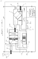
- FIG. 4 is a diagram of the first embodiment, showing adsorption operation in the dehumidifying operation mode;
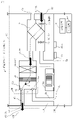
- FIG. 4 is a diagram of the first embodiment, showing regeneration operation in the dehumidifying operation mode;
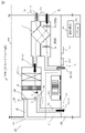
- FIG. 4 is a diagram of the first embodiment, showing adsorption operation in the humidification operation mode;
- FIG. 4 is a diagram of the first embodiment, showing regeneration operation in the humidification operation mode;
- Fig. 3 is a diagram of the first embodiment, showing a refrigeration cycle device 500 having the heat exchanger 10 as a first heat exchanger;
- 2 is a diagram of the first embodiment and shows a hardware configuration of the control device 101;
- FIG. FIG. 4 is a diagram of the first embodiment, showing air volume control of outside air 81 in a dehumidifying operation mode;
- FIG. 10 is a diagram of the first embodiment and is a flow chart showing control for changing the exhaust timing based on detection of a heat load;
- FIG. 10 is a diagram of the first embodiment and is a flow chart showing control for changing exhaust timing based on human detection;
- unit may be read as “circuit”, “process”, “procedure”, “process” or “circuitry” as appropriate.
- Embodiment 1 *** Configuration description *** An external air processing device 100 according to Embodiment 1 will be described with reference to FIGS. 1 to 9. FIG.
- ⁇ Dehumidification operation mode and humidification operation mode> There are two types of operation modes of the outside air processing device 100 . These two types are a dehumidification operation mode for dehumidifying the room 400 and a humidification operation mode for humidifying the room 400 .
- the dehumidifying operation mode the outside air processing device 100 supplies outside air 81 from which the moisture 4 is removed by the desiccant 20 to the room 400 .
- the humidification operation mode the outdoor air processing device 100 supplies the indoor air 81 with the moisture 4 desorbed from the desiccant 20 to the room 400 .
- Each operation mode has an adsorption operation and a desorption operation. That is, the dehumidifying operation mode has an adsorption operation and a desorption operation, and the humidification operation mode also has an adsorption operation and a desorption operation.
- the adsorption operation is an operation for causing the desiccant 20 to adsorb the moisture 4
- the desorption operation is an operation for desorbing the moisture from the desiccant 20 . Since the desorption operation is an operation for desorbing moisture from the desiccant 20, it is sometimes called a “regeneration operation”.
- the desorption operation is hereinafter referred to as "regeneration operation”.
- FIG. 1 shows the adsorption operation in the dehumidification operation mode of the outside air treatment device 100.
- FIG. 2 shows the regeneration operation in the dehumidification operation mode of the outside air treatment device 100.
- the outside air 81 in which the moisture 4 is adsorbed by the desiccant 20 is supplied to the room 400 , and the return air 82 from the room 400 is exhausted to the outside 420 .
- the outside air 81 that has obtained the moisture 4 from the desiccant 20 is exhausted to the outside 420 .
- the outside air processing device 100 includes an exhaust fan 2 a , an air supply fan 2 b , a total heat exchanger 8 , a heat exchanger 10 , a desiccant 20 and a damper device 30 .
- Desiccant 20 is a static dehumidifying device.
- the damper device 30 is a delivery device.
- the total heat exchanger 8 is provided with an exhaust fan 2a and an air supply fan 2b.
- the exhaust fan 2 a sends return air 82 and the supply air fan 2 b sends outside air 81 .
- the heat exchanger 10 functions as both a heater and a cooler, and exchanges heat with the outside air 81 .
- the heat exchanger 10 functions as either a heater or a cooler under the control of the refrigeration cycle device 500 by the device controller 112 .
- the heat exchanger 10 functions as a heater, it is written as a heater 10H, and when the heat exchanger 10 functions as a cooler, it is written as a cooler 10C.
- the heat exchanger 10 is installed to exchange heat with the outside air 81 .
- the desiccant 20 passes the outside air 81 that has exchanged heat with the heat exchanger 10 .
- the desiccant 20 adsorbs the moisture 4 from the outside air 81 when the outside air 81 cooled by the cooler 10C passes, and desorbs the moisture 4 to the outside air 81 when the outside air 81 heated by the heater 10H passes.
- the damper device 30 divides the outside air 81 that has passed through the desiccant 20 into the first flow path 41 and the second flow path 42 based on whether the heat exchanger 10 functions as the heater 10H or the cooler 10C. selectively delivered to one of the channels. As will be described later, in the dehumidifying operation mode, the damper device 30 sends the outside air 81 that has passed through the desiccant 20 to the second flow path 42 if the heat exchanger 10 is functioning as the heater 10H, If the heat exchanger 10 is functioning as the cooler 10 ⁇ /b>C, it is delivered to the first flow path 41 .
- the damper device 30 sends the outside air 81 that has passed through the desiccant 20 to the first flow path 41 if the heat exchanger 10 is functioning as the heater 10H. is functioning in the cooler 10C, it is sent to the second flow path 42.
- the damper device 30 has a first damper 31 and a second damper 32 .
- the first damper 31 has a door 31a and the second damper 32 has a door 32a. Doors 31a and 32a are opened and closed under the control of device control section 112 .
- the heat exchanger 10 and the desiccant 20 are arranged in order downstream of the air passage of the outside air 81 , and the damper device 30 is arranged downstream of the desiccant 20 .
- the first damper 31 opens and closes the first flow path 41 for supplying the outside air 81 to the room 400
- the second damper 32 opens and closes the second flow path 42 for discharging the outside air 81 to the outside 420 . .
- the outside air processing device 100 further includes a control device 101 and an input device 102 for inputting information to the control device 101 .
- the user of the outside air processing device 100 can input from the input device 102 whether to operate the outside air processing device 100 in the dehumidifying operation mode or the humidifying operation mode.
- the outside air processing device 100 is installed in the ceiling space 410 .
- An air conditioner 300 is also installed in the ceiling space 410 .
- the air conditioner 300 air-conditions the room 400 .
- a temperature sensor 113 a and a temperature sensor 113 a are installed in the room 400 .
- the temperature sensor 113a is used in control for changing the exhaust timing by detecting a heat load, which will be described later with reference to FIG.
- the temperature sensor 115a is used in control for changing the exhaust timing based on human detection, which will be described later with reference to FIG.
- the damper device 30 supplies the first flow path 41 to the supply flow path leading to the ventilation area, which is the area to which the outside air 81 is supplied and where the air is exhausted as the outside air 81 is supplied. As channel 42, it is delivered to another area channel leading to another area different from the ventilation area.
- the indoor 400 is a ventilation area
- the outdoor 420 is another area different from the ventilation area.
- the outside air processing device 100 includes a control device 101 .
- the control device 101 causes the instruction receiving unit 111 that receives a dehumidifying instruction to instruct the dehumidifying operation mode via the input device 102, and the heat exchanger 10 to function as either the heater 10H or the cooler 10C.
- the device control unit 112 causes the damper device 30 to flow the outside air 81 into another region in response to the heat exchanger 10 functioning as the heater 10H.
- the outside air 81 is sent to the damper device 30 in response to the fact that the heat exchanger 10 is made to function as the cooler 10C and the first flow path that is the supply flow path. 41.
- FIG. 3 shows adsorption operation in the humidification operation mode of the outside air treatment device 100 .
- FIG. 4 shows regeneration operation in the humidification operation mode of the outside air processing device 100 .
- the configurations of FIGS. 3 and 4 are the same as those of FIGS. 1 and 2, but the flow of outside air 81 and return air 82 is different.
- the outside air 81 in which the moisture 4 is adsorbed by the desiccant 20 is exhausted to the outside 420 .
- the regeneration operation in the humidification operation mode the outside air 81 that has obtained the moisture 4 from the desiccant 20 is supplied to the room 400 , and the return air 82 from the room 400 is exhausted to the outside 420 .
- the instruction receiving unit 111 receives, via the input device 102, a humidification instruction instructing the humidification operation mode.
- the device control unit 112 supplies the outside air 81 to the damper device 30 in response to the heat exchanger 10 functioning as the heater 10H. and the heat exchanger 10 functions as the cooler 10C. 42.
- FIG. 5 shows a refrigeration cycle device 500 for causing heat exchanger 10 to function as heater 10H and cooler 10C.
- the refrigeration cycle device 500 includes a compressor 501 , a four-way valve 502 , a heat exchanger 10 as a first heat exchanger, an expansion valve 503 and a second heat exchanger 504 .
- the heat exchanger 10 functions as either the heater 10H or the cooler 10C.
- the device control unit 112 controls the frequency of the compressor 501 to control the temperature of the heat exchanger 10 .
- FIG. 6 shows the hardware configuration of the control device 101.
- the control device 101 is a computer.
- the control device 101 comprises a processor 110 .
- the control device 101 includes other hardware such as a main memory device 120 , an auxiliary memory device 130 , an input interface 140 , an output interface 150 and a communication interface 160 in addition to the processor 110 .
- Processor 110 is connected to other hardware via signal line 170 and controls the other hardware.
- the control device 101 includes an instruction receiving unit 111, a device control unit 112, a heat load detection unit 113, and a human detection unit 114 as functional elements. Functions of the instruction receiving unit 111 , the device control unit 112 , the heat load detection unit 113 and the human detection unit 114 are implemented by the control program 103 .
- the processor 110 is a device that executes the control program 103 .
- the control program 103 is a program that implements the functions of the instruction receiving unit 111 , device control unit 112 , heat load detection unit 113 and human detection unit 114 .
- the processor 110 is an IC (Integrated Circuit) that performs arithmetic processing. Specific examples of the processor 110 are a CPU (Central Processing Unit), a DSP (Digital Signal Processor), and a GPU (Graphics Processing Unit).
- the main storage device 120 stores data in a volatile manner. Specific examples of the main memory device 120 are SRAM (Static Random Access Memory) and DRAM (Dynamic Random Access Memory). The main memory device 120 holds the computation results of the processor 110 .
- the auxiliary storage device 130 stores data in a non-volatile manner.
- a specific example of the auxiliary storage device 130 is an HDD (Hard Disk Drive).
- the auxiliary storage device 130 is a portable recording medium such as an SD (registered trademark) (Secure Digital) memory card, NAND flash, flexible disk, optical disk, compact disk, Blu-ray (registered trademark) disk, DVD (Digital Versatile Disk). There may be.
- the auxiliary storage device 130 stores the control program 103 .
- the input interface 140 is a port through which data is input from each device.
- the output interface 150 is a port to which various devices are connected and data is output from the processor 110 to the various devices.
- the input device 102 is connected to the input interface 140 .
- the communication interface 160 is a communication port for the processor 110 to communicate with other devices.
- the communication interface 160 is connected to the first damper 31, the second damper 32, the exhaust fan 2a, the air supply fan 2b, the temperature sensor 113a, the human sensor 114a, and the refrigeration cycle device 500.
- the processor 110 loads the control program 103 from the auxiliary storage device 130 to the main storage device 120, reads the control program 103 from the main storage device 120, and executes it.
- the control device 101 may include multiple processors in place of the processor 110 . These multiple processors share the execution of the control program 103 .
- Each processor like processor 110 , is a device that executes control program 103 . Data, information, signal values and variable values used, processed or output by control program 103 are stored in main memory 120 , auxiliary memory 130 , or registers or cache memory within processor 110 .
- each processing, each procedure or It is a program that causes a computer to execute each step.
- control method is a method performed by the control device 101, which is a computer, executing the control program 103.
- the control program 103 may be stored in a computer-readable recording medium and provided, or may be provided as a program product.
- Adsorption operation in dehumidification operation mode The adsorption operation in the dehumidifying operation mode will be described with reference to FIG.
- the device control unit 112 operates both the exhaust fan 2a and the air supply fan 2b.
- Heat exchanger 10 (cooler 10C): The outside air 81 that has passed through the total heat exchanger 8 is cooled by exchanging heat with the heat exchanger 10 functioning as the cooler 10C under the control of the device control unit 112, thereby increasing the relative humidity.
- Desiccant 20 Outside air 81 with a high relative humidity passes through the desiccant 20 . At this time, the desiccant 20 adsorbs the moisture 4 in the outside air 81 .
- Damper device 30 Under the control of the device control section 112, the door 31a of the first damper 31 is open and the door 32a of the second damper 32 is closed.
- the outside air 81 dehumidified by the desiccant 20 passes through the first damper 31 , is sent to the first flow path 41 , and is supplied from the outside air supply port 61 into the room 400 .
- the device control unit 112 operates the exhaust fan 2a.
- the return air 82 in the room 400 is sucked into the return air intake port 51 , passes through the exhaust fan 2 a and the total heat exchanger 8 , and is exhausted from the return air discharge port 62 to the outside 420 .
- Regenerative operation in dehumidifying operation mode The regeneration operation in the dehumidifying operation mode will be described with reference to FIG. Regenerative operation is as follows. During the regeneration operation, as shown in FIG. 2, the device control section 112 stops the exhaust fan 2a and operates only the air supply fan 2b. Further, the device control unit 112 causes the heat exchanger 10 to function as the heater 10H. (1) Total heat exchanger 8: Outside air 81 is sucked into the air supply fan 2 b from the outside air intake port 52 and passes through the total heat exchanger 8 . Since the return air 82 in the room 400 is not discharged as will be described later, the outside air 81 does not exchange total heat with the return air 82 in the total heat exchanger 8 .
- Heat exchanger 10 (heater 10H): The outside air 81 that has passed through the total heat exchanger 8 is heated by exchanging heat with the heat exchanger 10 functioning as the heater 10H under the control of the device control unit 112, thereby reducing the relative humidity.
- Desiccant 20 Outside air 81 with a low relative humidity passes through the desiccant 20 . At this time, the moisture 4 adsorbed to the desiccant 20 is desorbed to the outside air 81 .
- Damper device 30 Under the control of the device control section 112, the door 31a of the first damper 31 is closed and the door 32a of the second damper 32 is open.
- the outside air 81 humidified by the desiccant 20 passes through the second damper 32 , is sent to the second flow path 42 , and is discharged from the outside air outlet 63 to the outside 420 .
- the exhaust fan 2 a Since the exhaust fan 2 a is in a stopped state, the return air 82 in the room 400 is not discharged from the return air discharge port 62 .
- Adsorption operation in humidification operation mode The adsorption operation in the humidification operation mode will be described with reference to FIG. As shown in FIG. 3, during the adsorption operation, the device control unit 112 stops the exhaust fan 2a and operates only the air supply fan 2b.
- Total heat exchanger 8 Outside air 81 is sucked into the air supply fan 2 b from the outside air intake port 52 and passes through the total heat exchanger 8 .
- Desiccant 20 Outside air 81 with a high relative humidity passes through the desiccant 20 . At this time, the desiccant 20 adsorbs the moisture 4 in the outside air 81 .
- Damper device 30 Under the control of the device control section 112, the door 31a of the first damper 31 is closed and the door 32a of the second damper 32 is open. The outside air 81 dehumidified by the desiccant 20 passes through the second damper 32 , is sent to the second flow path 42 , and is supplied from the outside air outlet 63 to the outside 420 .
- Return air 82 Since the exhaust fan 2 a is in a stopped state, the return air 82 in the room 400 is not discharged from the return air discharge port 62 .
- Heat exchanger 10 (heater 10H): The outside air 81 that has passed through the total heat exchanger 8 is heated by exchanging heat with the heat exchanger 10 functioning as the heater 10H under the control of the device control unit 112, thereby reducing the relative humidity.
- Desiccant 20 Outside air 81 with a low relative humidity passes through the desiccant 20 . At this time, the moisture 4 adsorbed to the desiccant 20 is desorbed to the outside air 81 .
- Damper device 30 Under the control of the device control section 112, the door 31a of the first damper 31 is open and the door 32a of the second damper 32 is closed.
- the outside air 81 humidified by the desiccant 20 passes through the first damper 31 , is sent to the first flow path 41 , and is supplied from the outside air supply port 61 into the room 400 .
- the device control unit 112 operates the exhaust fan 2a.
- the return air 82 in the room 400 is sucked into the return air intake port 51 , passes through the exhaust fan 2 a and the total heat exchanger 8 , and is exhausted from the return air discharge port 62 to the outside 420 .
- FIG. 7 is a diagram showing air volume control of the outside air 81 in the dehumidifying operation mode.
- the horizontal axis indicates the supply time of the outside air 81 to the room 400 .
- the unit is minutes (min).
- the vertical axis indicates the unit supply air volume.
- the unit supply air volume is the air volume of the outside air 81 supplied to the room 400 per minute.
- the unit is m 3 /min.
- the outside air processing device 100 considers the ventilation stop time (exhaust stop period of the return air 82) during the regeneration operation in the dehumidifying operation mode, and satisfies the required ventilation amount per unit time. , to adjust the air supply volume.
- the apparatus control unit 112 controls the rotation speed of the air supply fan 2b to adjust the intake amount of the outside air 81, which is the amount of supply air, from the outside air intake port 52 in the adsorption operation in the dehumidification operation mode.
- a specific description will be made with one hour as the reference time.
- the device control unit 112 controls the refrigeration cycle device 500 to adjust the regeneration operation time (FIG. 2) for exhausting the outside air 81 to the outdoor 420.
- the amount of heating of the outside air 81 by the heater 10H during the regeneration operation may be controlled.
- the period "60-t1" in FIG. 7 can be accurately obtained, so that the ventilation volume can be controlled more accurately.
- the timing to start the regeneration operation for discharging the outside air 81 may be determined by a timer, or a certain time within the reference time (one hour in the above example), for example, 12:00 within the reference time. If it is included, it may be determined as 12 o'clock.
- the terms exhaust operation and supply operation are used. These have the following meanings.
- the exhaust operation is an operation in which the outside air 81 that has passed through the desiccant 20 is exhausted from the second flow path 42 to the outside 420 .
- the air supply operation is an operation in which the outside air 81 that has passed through the desiccant 20 is supplied from the first flow path 41 into the room 400 .
- the exhaust operation is the regeneration operation of FIG.
- the exhaust operation is the adsorption operation of FIG.
- the air supply operation is the adsorption operation of FIG.
- the air supply operation is the regeneration operation of FIG. Since the description here is for the dehumidification mode of operation, exhaust operation is regeneration operation. For example, in the morning, the load on the air conditioning system is high because the operation of the air conditioning system is started. For this reason, it is conceivable that the outside air processing device 100 performs an exhaust operation to suppress the amount of ventilation.
- the return air 82 in the room 400 is not exhausted to the outside 420, so the air in the room 400 is controlled by the air conditioning system so as to approach the set temperature without being ventilated. Therefore, the load on the air conditioning system is low.
- Adjustment of air supply air volume in humidification operation mode is the same as the adjustment of the air supply air volume in the dehumidification operation mode.
- the outside air 81 is supplied to the room 400 during the regeneration operation, and the outside air 81 is exhausted to the outside 420 during the adsorption operation. Therefore, the adjustment of the amount of supplied air in the humidification operation mode is performed during the regeneration operation.
- the device control unit 112 controls the refrigeration cycle device 500 to adjust the adsorption operation time for exhausting the outside air 81 to the outdoor 420. Cooling of the outside air 81 by the cooler 10C may be controlled. As a result, the period of "60-t1" in FIG. 07 can be accurately obtained, so that the ventilation volume can be controlled more accurately.
- the timing to start the adsorption operation for discharging the outside air 81 may be determined by a timer, or a certain time within the reference time (one hour in the above example), for example, 12:00 within the reference time. If it is included, it may be determined as 12 o'clock. Since this is a description of the humidification operation mode, the exhaust operation is the adsorption operation. For example, in the morning, the load on the air conditioning system is high because the operation of the air conditioning system is started. For this reason, it is conceivable that the outside air processing device 100 performs an exhaust operation to suppress the amount of ventilation.
- the return air 82 in the room 400 is not exhausted to the outside 420, so the air in the room 400 is controlled by the air conditioning system so as to approach the set temperature without being ventilated. Therefore, the load on the air conditioning system is low.
- FIG. 8 is a flowchart showing the operation of the outside air treatment device 100 when the outside air treatment device 100 is equipped with the heat load detection unit 113.
- the control device 101 includes a heat load detection unit 113 that detects the heat load of the air conditioner 300 that air-conditions the room 400, which is the ventilation area.
- the device control unit 112 causes the damper device 30 to send the outside air 81 to the second channel 42, which is the separate region channel, when the detected heat load is greater than the threshold value.
- the thermal load detection unit 113 is connected to the temperature sensor 113a via the communication interface 160, and detects the temperature Ti of the room 400 from the temperature sensor 113a. Also, the heat load detection unit 113 acquires the set temperature Ts of the room 400 for the air conditioner 300 via the communication interface 160 from an air conditioning control device (not shown) that controls the air conditioner 300 .
- Thermal load detection unit 113 detects a thermal load to be processed by air conditioner 300 .
- the thermal load is the difference ⁇ T between the set temperature Ts acquired by the thermal load detection unit 113 and the temperature Ti in the room 400 detected via the temperature sensor 113a.
- ⁇ T is given by Equation 4.
- ⁇ T is assumed to be the heat load.
- step S101 the instruction receiving unit 111 acquires the current time, the exhaust time setting value (corresponding to "60-t1" in FIG. 7), and the reference time (corresponding to 1 hour in FIG. 7).
- the thermal load detector 113 calculates the thermal load ⁇ T.
- Step S102> The thermal load detection unit 113 determines whether the thermal load ⁇ T is greater than the threshold TH1. If so, the process proceeds to step S103; otherwise, the process proceeds to step S109.
- step S103 the device control unit 112 determines whether the exhaust operation (the regeneration operation in the dehumidification operation mode and the adsorption operation in the humidification operation mode) is being performed within the reference time. If the exhaust operation has not been performed within the reference time, the process proceeds to step S104. If the exhaust operation is being performed within the reference time, the process proceeds to step S105.
- step S104 the device control unit 112 performs an exhaust operation.
- the exhaust operation is the regeneration operation in the dehumidification operation mode, and the adsorption operation in the humidification operation mode. Exhaust operation can suppress an increase in heat load due to an increase in ventilation.
- step S105 the device control unit 112 performs air supply operation.
- the air supply operation is the adsorption operation in the dehumidification operation mode, and the regeneration operation in the humidification operation mode.
- step S106 the device control unit 112 determines whether the exhaust time (equivalent to "60-t1"), which is the exhaust operation time, is equal to or greater than the exhaust time set value. If YES in step S106, the process proceeds to step S107, and if NO, the process proceeds to step S108.
- step S107> the device control unit 112 starts supplying the outside air 81 .
- the air supply operation is the adsorption operation in the dehumidification operation mode, and the regeneration operation in the humidification operation mode.
- step S108 the device control unit 112 continues the exhaust operation from step S104.
- the exhaust operation is the regeneration operation in the dehumidification operation mode, and the adsorption operation in the humidification operation mode.
- step S109 the device control unit 112 determines whether or not the exhaust operation is to be performed within a reference period of time (for example, within 60 minutes).
- the exhaust operation is the regeneration operation in the dehumidification operation mode, and the adsorption operation in the humidification operation mode. If the exhaust operation has not been performed within the reference time, the process proceeds to step S110. If the exhaust operation is being performed within the reference time, the process proceeds to step S113.
- Step S110 if the remaining time (elapsed time within the reference time) of the reference time (60 minutes) is equal to or less than the required exhaust operation time (YES in step S110), the device control unit 112 Move on to driving.
- the exhaust operation is the regeneration operation in the dehumidification operation mode, and the adsorption operation in the humidification operation mode.
- step S110 if the remaining time (elapsed time within the reference time) of the reference time (60 minutes) is greater than the required exhaust operation time (NO in step S110), device control unit 112 performs air supply in step S112. Continue driving.
- FIG. 9 is a flow chart showing the operation of the outside air processing device 100 including the human detection unit 114.
- the control device 101 includes a human detection unit 114 that detects the number of people present in the room 400, which is the ventilation area. When the number of people detected by the human detection unit 114 is smaller than the threshold TH2, the device control unit 112 causes the damper device 30 to send the outside air 81 to the second flow path 42, which is the separate area flow path. A specific description will be given below.
- the human detection unit 114 is connected to the human sensor 114a via the communication interface 160, and detects the number of people present in the room 400 from the human sensor 114a.
- FIG. 9 is similar to FIG. Steps S201 to S212 respectively correspond to steps S101 to S112. Steps S203 to S212 are the same as steps S103 to S112, respectively, except that steps S201 and S202 are different from steps S101 and S102. Therefore, steps S201 and S202 will be described.
- step S201 the instruction receiving unit 111 acquires the current time, the set value of the exhaust time, and the reference time.
- the human detection unit 114 acquires the number of people from the human sensor 114a.
- the human detection unit 114 detects the number of people present in the room 400 via the human sensor 114a.
- Step S202> The human detection unit 114 determines whether the detected number of people is smaller than a threshold TH2. If so, the process proceeds to step S203; otherwise, the process proceeds to step S209. Since the subsequent processing is the same as in FIG. 8 as described above, the description is omitted.
- the outside air processing device 100 of Embodiment 1 regenerates the desiccant 20 without using the return air 82 . Therefore, it is possible to prevent viruses and dust present in the room 400 from adhering to the desiccant 20 . As a result, viruses and dust can be prevented from diffusing into the room, and viruses and dust can be efficiently exhausted.
- the outside air processing device 100 adjusts the air volume in consideration of the ventilation stop time in the exhaust operation in which the outside air 81 is exhausted to the outside 420 . Therefore, the required ventilation volume per unit time can be satisfied. These can provide a healthy and comfortable space.
- the device control unit 112 of the outside air processing device 100 opens and closes the doors 31a and 32a of the damper device 30 depending on whether the heat exchanger 10 functions as the heater 10H or the cooler 10C. Since it is controlled, there is an effect that the outside air processing device 100 can be realized with a simple configuration.
Landscapes
- Engineering & Computer Science (AREA)
- Chemical & Material Sciences (AREA)
- Combustion & Propulsion (AREA)
- Mechanical Engineering (AREA)
- General Engineering & Computer Science (AREA)
- Signal Processing (AREA)
- Physics & Mathematics (AREA)
- Fuzzy Systems (AREA)
- Mathematical Physics (AREA)
- Central Air Conditioning (AREA)
- Air Conditioning Control Device (AREA)
Priority Applications (3)
| Application Number | Priority Date | Filing Date | Title |
|---|---|---|---|
| PCT/JP2021/003358 WO2022162901A1 (ja) | 2021-01-29 | 2021-01-29 | 外気処理装置 |
| JP2022577974A JP7395030B2 (ja) | 2021-01-29 | 2021-01-29 | 外気処理装置 |
| US18/254,629 US20230408131A1 (en) | 2021-01-29 | 2021-01-29 | Outdoor air processing apparatus |
Applications Claiming Priority (1)
| Application Number | Priority Date | Filing Date | Title |
|---|---|---|---|
| PCT/JP2021/003358 WO2022162901A1 (ja) | 2021-01-29 | 2021-01-29 | 外気処理装置 |
Publications (1)
| Publication Number | Publication Date |
|---|---|
| WO2022162901A1 true WO2022162901A1 (ja) | 2022-08-04 |
Family
ID=82654375
Family Applications (1)
| Application Number | Title | Priority Date | Filing Date |
|---|---|---|---|
| PCT/JP2021/003358 Ceased WO2022162901A1 (ja) | 2021-01-29 | 2021-01-29 | 外気処理装置 |
Country Status (3)
| Country | Link |
|---|---|
| US (1) | US20230408131A1 (https=) |
| JP (1) | JP7395030B2 (https=) |
| WO (1) | WO2022162901A1 (https=) |
Families Citing this family (1)
| Publication number | Priority date | Publication date | Assignee | Title |
|---|---|---|---|---|
| CN118647169A (zh) * | 2023-03-13 | 2024-09-13 | 开利公司 | 冷却系统和用于其的预处理模块 |
Citations (2)
| Publication number | Priority date | Publication date | Assignee | Title |
|---|---|---|---|---|
| JP2005291569A (ja) * | 2004-03-31 | 2005-10-20 | Daikin Ind Ltd | 空気調和機およびその制御方法 |
| JP2015072106A (ja) * | 2013-10-04 | 2015-04-16 | ダイキン工業株式会社 | 加湿装置 |
Family Cites Families (1)
| Publication number | Priority date | Publication date | Assignee | Title |
|---|---|---|---|---|
| US6364942B1 (en) * | 2000-03-06 | 2002-04-02 | Honeywell International Inc. | Dehumidifier using non-rotating desiccant material |
-
2021
- 2021-01-29 JP JP2022577974A patent/JP7395030B2/ja active Active
- 2021-01-29 WO PCT/JP2021/003358 patent/WO2022162901A1/ja not_active Ceased
- 2021-01-29 US US18/254,629 patent/US20230408131A1/en not_active Abandoned
Patent Citations (2)
| Publication number | Priority date | Publication date | Assignee | Title |
|---|---|---|---|---|
| JP2005291569A (ja) * | 2004-03-31 | 2005-10-20 | Daikin Ind Ltd | 空気調和機およびその制御方法 |
| JP2015072106A (ja) * | 2013-10-04 | 2015-04-16 | ダイキン工業株式会社 | 加湿装置 |
Also Published As
| Publication number | Publication date |
|---|---|
| JPWO2022162901A1 (https=) | 2022-08-04 |
| JP7395030B2 (ja) | 2023-12-08 |
| US20230408131A1 (en) | 2023-12-21 |
Similar Documents
| Publication | Publication Date | Title |
|---|---|---|
| JP5862266B2 (ja) | 換気システム | |
| JP5229368B2 (ja) | 調湿装置 | |
| JP2000220877A (ja) | 換気空調機 | |
| KR102556842B1 (ko) | 2-로터 제습 시스템 | |
| JP3567860B2 (ja) | 加湿装置およびそれを用いた空気調和機 | |
| JP6779653B2 (ja) | 外気処理システム、外気処理システムの制御装置及び制御方法 | |
| JP7395030B2 (ja) | 外気処理装置 | |
| WO2022264350A1 (ja) | 換気システム | |
| JP2010117112A (ja) | 空気調和機 | |
| JP3099589B2 (ja) | 除加湿装置 | |
| JP3099590B2 (ja) | 除加湿装置 | |
| CN118391730A (zh) | 空调机 | |
| JP6452368B2 (ja) | 燃料電池装置利用型空調システム | |
| JP2022150197A (ja) | 浴室空調装置 | |
| JP7804917B2 (ja) | 空気調和機、空気調和機の制御方法、プログラム及びコンピュータ読み取り可能な記憶媒体 | |
| JP7788674B2 (ja) | 空気調和機 | |
| JP3099588B2 (ja) | 除加湿装置 | |
| JP7777772B2 (ja) | 空気調和機 | |
| JP2001193981A (ja) | 除湿換気装置 | |
| JP2024058407A (ja) | 空気調和機、空気調和機の制御方法、プログラム及びコンピュータ読み取り可能な記憶媒体 | |
| JP2025115588A (ja) | 空気調和機 | |
| JP2025115585A (ja) | 空気調和機 | |
| CN118347136A (zh) | 空调机、空调机的控制方法和计算机可读存储介质 | |
| CN118361848A (zh) | 空调机、空调机的控制方法和计算机可读存储介质 | |
| CN114623513A (zh) | 加湿装置的控制方法、装置、存储介质及空调器 |
Legal Events
| Date | Code | Title | Description |
|---|---|---|---|
| 121 | Ep: the epo has been informed by wipo that ep was designated in this application |
Ref document number: 21922916 Country of ref document: EP Kind code of ref document: A1 |
|
| ENP | Entry into the national phase |
Ref document number: 2022577974 Country of ref document: JP Kind code of ref document: A |
|
| WWE | Wipo information: entry into national phase |
Ref document number: 18254629 Country of ref document: US |
|
| NENP | Non-entry into the national phase |
Ref country code: DE |
|
| 122 | Ep: pct application non-entry in european phase |
Ref document number: 21922916 Country of ref document: EP Kind code of ref document: A1 |