WO2022162901A1 - Outside-air processing device - Google Patents
Outside-air processing device Download PDFInfo
- Publication number
- WO2022162901A1 WO2022162901A1 PCT/JP2021/003358 JP2021003358W WO2022162901A1 WO 2022162901 A1 WO2022162901 A1 WO 2022162901A1 JP 2021003358 W JP2021003358 W JP 2021003358W WO 2022162901 A1 WO2022162901 A1 WO 2022162901A1
- Authority
- WO
- WIPO (PCT)
- Prior art keywords
- outside air
- air
- heat exchanger
- flow path
- cooler
- Prior art date
Links
- 230000006870 function Effects 0.000 claims abstract description 22
- 238000001514 detection method Methods 0.000 claims description 30
- 238000007791 dehumidification Methods 0.000 claims description 25
- 238000009423 ventilation Methods 0.000 claims description 23
- 230000004044 response Effects 0.000 claims description 6
- 239000002274 desiccant Substances 0.000 abstract description 56
- 238000001179 sorption measurement Methods 0.000 description 31
- 230000008929 regeneration Effects 0.000 description 29
- 238000011069 regeneration method Methods 0.000 description 29
- 238000000034 method Methods 0.000 description 16
- 238000004378 air conditioning Methods 0.000 description 11
- 238000010586 diagram Methods 0.000 description 10
- 238000005057 refrigeration Methods 0.000 description 9
- 238000004891 communication Methods 0.000 description 8
- 241000700605 Viruses Species 0.000 description 7
- 238000003795 desorption Methods 0.000 description 7
- 239000000428 dust Substances 0.000 description 7
- 230000001172 regenerating effect Effects 0.000 description 5
- 230000003068 static effect Effects 0.000 description 4
- 238000007599 discharging Methods 0.000 description 3
- 230000000694 effects Effects 0.000 description 2
- 238000001816 cooling Methods 0.000 description 1
- 238000005516 engineering process Methods 0.000 description 1
- 238000010438 heat treatment Methods 0.000 description 1
- 230000003287 optical effect Effects 0.000 description 1
Images


Classifications
-
- F—MECHANICAL ENGINEERING; LIGHTING; HEATING; WEAPONS; BLASTING
- F24—HEATING; RANGES; VENTILATING
- F24F—AIR-CONDITIONING; AIR-HUMIDIFICATION; VENTILATION; USE OF AIR CURRENTS FOR SCREENING
- F24F11/00—Control or safety arrangements
- F24F11/70—Control systems characterised by their outputs; Constructional details thereof
- F24F11/72—Control systems characterised by their outputs; Constructional details thereof for controlling the supply of treated air, e.g. its pressure
-
- F—MECHANICAL ENGINEERING; LIGHTING; HEATING; WEAPONS; BLASTING
- F24—HEATING; RANGES; VENTILATING
- F24F—AIR-CONDITIONING; AIR-HUMIDIFICATION; VENTILATION; USE OF AIR CURRENTS FOR SCREENING
- F24F11/00—Control or safety arrangements
- F24F11/0008—Control or safety arrangements for air-humidification
-
- F—MECHANICAL ENGINEERING; LIGHTING; HEATING; WEAPONS; BLASTING
- F24—HEATING; RANGES; VENTILATING
- F24F—AIR-CONDITIONING; AIR-HUMIDIFICATION; VENTILATION; USE OF AIR CURRENTS FOR SCREENING
- F24F11/00—Control or safety arrangements
- F24F11/62—Control or safety arrangements characterised by the type of control or by internal processing, e.g. using fuzzy logic, adaptive control or estimation of values
- F24F11/63—Electronic processing
- F24F11/65—Electronic processing for selecting an operating mode
-
- F—MECHANICAL ENGINEERING; LIGHTING; HEATING; WEAPONS; BLASTING
- F24—HEATING; RANGES; VENTILATING
- F24F—AIR-CONDITIONING; AIR-HUMIDIFICATION; VENTILATION; USE OF AIR CURRENTS FOR SCREENING
- F24F3/00—Air-conditioning systems in which conditioned primary air is supplied from one or more central stations to distributing units in the rooms or spaces where it may receive secondary treatment; Apparatus specially designed for such systems
- F24F3/12—Air-conditioning systems in which conditioned primary air is supplied from one or more central stations to distributing units in the rooms or spaces where it may receive secondary treatment; Apparatus specially designed for such systems characterised by the treatment of the air otherwise than by heating and cooling
- F24F3/14—Air-conditioning systems in which conditioned primary air is supplied from one or more central stations to distributing units in the rooms or spaces where it may receive secondary treatment; Apparatus specially designed for such systems characterised by the treatment of the air otherwise than by heating and cooling by humidification; by dehumidification
- F24F3/1411—Air-conditioning systems in which conditioned primary air is supplied from one or more central stations to distributing units in the rooms or spaces where it may receive secondary treatment; Apparatus specially designed for such systems characterised by the treatment of the air otherwise than by heating and cooling by humidification; by dehumidification by absorbing or adsorbing water, e.g. using an hygroscopic desiccant
- F24F3/1429—Air-conditioning systems in which conditioned primary air is supplied from one or more central stations to distributing units in the rooms or spaces where it may receive secondary treatment; Apparatus specially designed for such systems characterised by the treatment of the air otherwise than by heating and cooling by humidification; by dehumidification by absorbing or adsorbing water, e.g. using an hygroscopic desiccant alternatively operating a heat exchanger in an absorbing/adsorbing mode and a heat exchanger in a regeneration mode
-
- F—MECHANICAL ENGINEERING; LIGHTING; HEATING; WEAPONS; BLASTING
- F24—HEATING; RANGES; VENTILATING
- F24F—AIR-CONDITIONING; AIR-HUMIDIFICATION; VENTILATION; USE OF AIR CURRENTS FOR SCREENING
- F24F3/00—Air-conditioning systems in which conditioned primary air is supplied from one or more central stations to distributing units in the rooms or spaces where it may receive secondary treatment; Apparatus specially designed for such systems
- F24F3/12—Air-conditioning systems in which conditioned primary air is supplied from one or more central stations to distributing units in the rooms or spaces where it may receive secondary treatment; Apparatus specially designed for such systems characterised by the treatment of the air otherwise than by heating and cooling
- F24F3/14—Air-conditioning systems in which conditioned primary air is supplied from one or more central stations to distributing units in the rooms or spaces where it may receive secondary treatment; Apparatus specially designed for such systems characterised by the treatment of the air otherwise than by heating and cooling by humidification; by dehumidification
- F24F2003/144—Air-conditioning systems in which conditioned primary air is supplied from one or more central stations to distributing units in the rooms or spaces where it may receive secondary treatment; Apparatus specially designed for such systems characterised by the treatment of the air otherwise than by heating and cooling by humidification; by dehumidification by dehumidification only
-
- F—MECHANICAL ENGINEERING; LIGHTING; HEATING; WEAPONS; BLASTING
- F24—HEATING; RANGES; VENTILATING
- F24F—AIR-CONDITIONING; AIR-HUMIDIFICATION; VENTILATION; USE OF AIR CURRENTS FOR SCREENING
- F24F2110/00—Control inputs relating to air properties
- F24F2110/20—Humidity
-
- Y—GENERAL TAGGING OF NEW TECHNOLOGICAL DEVELOPMENTS; GENERAL TAGGING OF CROSS-SECTIONAL TECHNOLOGIES SPANNING OVER SEVERAL SECTIONS OF THE IPC; TECHNICAL SUBJECTS COVERED BY FORMER USPC CROSS-REFERENCE ART COLLECTIONS [XRACs] AND DIGESTS
- Y02—TECHNOLOGIES OR APPLICATIONS FOR MITIGATION OR ADAPTATION AGAINST CLIMATE CHANGE
- Y02B—CLIMATE CHANGE MITIGATION TECHNOLOGIES RELATED TO BUILDINGS, e.g. HOUSING, HOUSE APPLIANCES OR RELATED END-USER APPLICATIONS
- Y02B30/00—Energy efficient heating, ventilation or air conditioning [HVAC]
- Y02B30/56—Heat recovery units
Abstract
Description
加熱器としても冷却器としても機能し、外気と熱交換する熱交換器と、
前記熱交換器と熱交換した前記外気が通過する静止型除湿デバイスと、
前記静止型除湿デバイスを通過した前記外気を、前記熱交換器が加熱器と冷却器とのどちらで機能しているかに基づいて、第1流路と第2流路との何れか一方の流路へ選択的に送出する送出装置と、
を備える。 The outside air processing device according to the present disclosure is
a heat exchanger that functions as both a heater and a cooler and that exchanges heat with the outside air;
a stationary dehumidification device through which the outside air that has exchanged heat with the heat exchanger passes;
The outside air that has passed through the stationary dehumidification device is directed to either the first flow path or the second flow path based on whether the heat exchanger functions as a heater or a cooler. a delivery device for selectively delivering to a path;
Prepare.
***構成の説明***
図1から図9を参照して、実施の形態1の外気処理装置100を説明する。 Embodiment 1.
*** Configuration description ***
An external
外気処理装置100の運転モードには2種類ある。この2種類は、室内400を除湿する除湿運転モードと、室内400を加湿する加湿運転モードである。除湿運転モードでは、外気処理装置100は、デシカント20によって水分4を除いた外気81を、室内400に供給する。加湿運転モードでは、外気処理装置100は、デシカント20から脱着した水分4が与えられた外気81を、室内400に供給する。 <Dehumidification operation mode and humidification operation mode>
There are two types of operation modes of the outside
また、それぞれの運転モードにおいて、吸着運転と脱着運転がある。つまり、除湿運転モードには吸着運転と脱着運転があり、加湿運転モードにも吸着運転と脱着運転がある。吸着運転とはデシカント20に水分4を吸着させる運転であり、脱着運転とはデシカント20から水分を脱着する運転である。脱着運転はデシカント20から水分を脱着する運転であるため「再生運転」と呼ばれることがある。以下では脱着運転を「再生運転」と表記する。 <Adsorption operation and desorption operation>
Each operation mode has an adsorption operation and a desorption operation. That is, the dehumidifying operation mode has an adsorption operation and a desorption operation, and the humidification operation mode also has an adsorption operation and a desorption operation. The adsorption operation is an operation for causing the
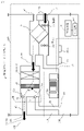
図1は、外気処理装置100の除湿運転モードにおける吸着運転を示す。
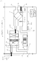
図2は、外気処理装置100の除湿運転モードにおける再生運転を示す。
除湿運転モードにおける吸着運転では、デシカント20によって水分4の吸着された外気81が室内400へ供給され、また、室内400の還気82が室外420へ排気される。除湿運転モードにおける再生運転では、デシカント20から水分4を得た外気81が室外420へ排気される。 <Dehumidifying operation mode>
FIG. 1 shows the adsorption operation in the dehumidification operation mode of the outside
FIG. 2 shows the regeneration operation in the dehumidification operation mode of the outside
In the adsorption operation in the dehumidifying operation mode, the
図1を参照して、外気処理装置100の構成を説明する。外気処理装置100は、排気ファン2a、給気ファン2b、全熱交換器8、熱交換器10、デシカント20及びダンパー装置30を備えている。デシカント20は静止型除湿デバイスである。ダンパー装置30は送出装置である。全熱交換器8には排気ファン2a、給気ファン2bが設置されている。排気ファン2aが還気82を送り、給気ファン2bが外気81を送る。熱交換器10は、加熱器としても冷却器としても機能し、外気81と熱交換する。熱交換器10は、冷凍サイクル装置500への装置制御部112の制御によって、加熱器と冷却器とのどちらでも機能する。熱交換器10が加熱器として機能する場合には加熱器10Hと表記し、熱交換器10が冷却器として機能する場合には冷却器10Cと表記する。熱交換器10は外気81と熱交換するために設置されている。デシカント20は、熱交換器10と熱交換した外気81が通過する。デシカント20は、冷却器10Cに冷やされた外気81が通過するときには、外気81から水分4を吸着し、加熱器10Hに加熱された外気81が通過するときには、外気81へ水分4を脱着する。ダンパー装置30は、デシカント20を通過した外気81を、熱交換器10が加熱器10Hと冷却器10Cとのどちらで機能しているかに基づいて、第1流路41と第2流路42との何れか一方の流路へ選択的に送出する。後述のように、除湿運転モードの場合には、ダンパー装置30は、デシカント20を通過した外気81を、熱交換器10が加熱器10Hで機能してれば第2流路42へ送出し、熱交換器10が冷却器10Cで機能していれば、第1流路41へ送出する。また加湿運転モードの場合には、ダンパー装置30は、デシカント20を通過した外気81を、熱交換器10が加熱器10Hで機能してれば第1流路41へ送出し、熱交換器10が冷却器10Cで機能していれば、第2流路42へ送出する。ダンパー装置30は、第1ダンパー31と第2ダンパー32とを備えている。第1ダンパー31は扉31aを備え、第2ダンパー32は扉32aを備える。扉31aおよび扉32aは、装置制御部112の制御によって開閉する。 <Configuration of outside
The configuration of the outside
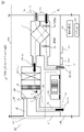
図3は、外気処理装置100の加湿運転モードにおける吸着運転を示す。
図4は、外気処理装置100の加湿運転モードにおける再生運転を示す。
図3および図4の構成は、図1および図2と同じであるが、外気81と還気82の流れ方が異なる。加湿運転モードにおける吸着運転では、デシカント20によって水分4の吸着された外気81が室外420へ排気される。加湿運転モードにおける再生運転では、デシカント20から水分4を得た外気81が室内400へ供給され、また、室内400の還気82が室外420へ排気される。 <Humidification operation mode>
FIG. 3 shows adsorption operation in the humidification operation mode of the outside
FIG. 4 shows regeneration operation in the humidification operation mode of the outside
The configurations of FIGS. 3 and 4 are the same as those of FIGS. 1 and 2, but the flow of
図5は、熱交換器10を加熱器10Hおよび冷却器10Cとして機能させるための冷凍サイクル装置500を示す。冷凍サイクル装置500は、圧縮機501、四方弁502、第1熱交換器である熱交換器10、膨張弁503、第2熱交換器504を備えている。制御装置101の装置制御部112が四方弁502を切り替えることで、熱交換器10は加熱器10Hと冷却器10Cとのいずれかとして機能する。また装置制御部112が圧縮機501の周波数を制御することで、熱交換器10の温度を制御する。 <
FIG. 5 shows a
<A1.除湿運転モードでの吸着運転>
図1を参照して除湿運転モードでの吸着運転を説明する。図1に示すように、吸着運転時には、装置制御部112は、排気ファン2aおよび給気ファン2bの両方を稼働させる。
(1)全熱交換器8:
外気81は、外気吸入口52から給気ファン2bに吸い込まれ、全熱交換器8を通過する。このとき外気81は全熱交換器8を通過する還気82と全熱交換する。
(2)熱交換器10(冷却器10C):
全熱交換器8を通過した外気81は、装置制御部112の制御によって冷却器10Cとして機能している熱交換器10と熱交換して冷やされて、相対湿度が高まる。
(3)デシカント20:
相対湿度の高い外気81は、デシカント20を通過する。この時、デシカント20は、外気81の水分4を吸着する。
(4)ダンパー装置30:
装置制御部112の制御によって、第1ダンパー31の扉31aは開いており、第2ダンパー32の扉32aは閉じている。デシカント20によって除湿された外気81は、第1ダンパー31を通過して第1流路41へ送出され、外気供給口61から室内400へ供給される。
(5)還気82:
装置制御部112は排気ファン2aを稼働している。室内400の還気82は還気吸入口51へ吸い込まれて排気ファン2a、全熱交換器8を経て、還気排出口62から室外420へ排気される。 ***Description of operation***
<A1. Adsorption operation in dehumidification operation mode>
The adsorption operation in the dehumidifying operation mode will be described with reference to FIG. As shown in FIG. 1, during the adsorption operation, the
(1) Total heat exchanger 8:
(2) Heat exchanger 10 (cooler 10C):
The
(3) Desiccant 20:
(4) Damper device 30:
Under the control of the
(5) Return air 82:
The
図2を参照して除湿運転モードでの再生運転を説明する。再生運転は以下のようである。再生運転時には図2に示すように、装置制御部112は、排気ファン2aを停止させ、給気ファン2bのみを稼働する。また、装置制御部112は、熱交換器10を加熱器10Hとして機能させる。
(1)全熱交換器8:
外気81は、外気吸入口52から給気ファン2bに吸い込まれ、全熱交換器8を通過する。後述のように室内400の還気82は排気されないので、外気81は全熱交換器8において還気82と全熱交換はしない。
(2)熱交換器10(加熱器10H):
全熱交換器8を通過した外気81は、装置制御部112の制御によって加熱器10Hとして機能している熱交換器10と熱交換して加熱されて、相対湿度が低下する。
(3)デシカント20:
相対湿度の低い外気81は、デシカント20を通過する。この時、デシカント20に吸着されている水分4は、外気81へ脱着する。
(4)ダンパー装置30:
装置制御部112の制御によって、第1ダンパー31の扉31aは閉じており、第2ダンパー32の扉32aは開いている。デシカント20によって加湿された外気81は、第2ダンパー32を通過して第2流路42へ送出され、外気排出口63から室外420へ排出される。
(5)排気ファン2aは停止状態なので、室内400の還気82は、還気排出口62から排出されない。 <A2. Regenerative operation in dehumidifying operation mode>
The regeneration operation in the dehumidifying operation mode will be described with reference to FIG. Regenerative operation is as follows. During the regeneration operation, as shown in FIG. 2, the
(1) Total heat exchanger 8:
(2) Heat exchanger 10 (
The
(3) Desiccant 20:
(4) Damper device 30:
Under the control of the
(5) Since the
図3を参照して加湿運転モードでの吸着運転を説明する。図3に示すように、吸着運転時には、装置制御部112は、排気ファン2aを停止し、給気ファン2bのみを稼働させる。
(1)全熱交換器8:
外気81は、外気吸入口52から給気ファン2bに吸い込まれ、全熱交換器8を通過する。
(2)熱交換器10(冷却器10C):
全熱交換器8を通過した外気81は、装置制御部112の制御によって冷却器10Cとして機能している熱交換器10と熱交換して冷やされて、相対湿度が高まる。
(3)デシカント20:
相対湿度の高い外気81は、デシカント20を通過する。この時、デシカント20は、外気81の水分4を吸着する。
(4)ダンパー装置30:
装置制御部112の制御によって、第1ダンパー31の扉31aは閉じており、第2ダンパー32の扉32aは開いている。デシカント20によって除湿された外気81は、第2ダンパー32を通過して第2流路42へ送出され、外気排出口63から室外420へ供給される。
(5)還気82:
排気ファン2aは停止状態なので、室内400の還気82は、還気排出口62から排出されない。 <B1. Adsorption operation in humidification operation mode>
The adsorption operation in the humidification operation mode will be described with reference to FIG. As shown in FIG. 3, during the adsorption operation, the
(1) Total heat exchanger 8:
(2) Heat exchanger 10 (cooler 10C):
The
(3) Desiccant 20:
(4) Damper device 30:
Under the control of the
(5) Return air 82:
Since the
図4を参照して加湿運転モードでの再生運転を説明する。図4に示すように、再生運転時には、装置制御部112は、排気ファン2aおよび給気ファン2bの両方を稼働させる。
(1)全熱交換器8:
外気81は、外気吸入口52から給気ファン2bに吸い込まれ、全熱交換器8を通過する。このとき外気81は全熱交換器8を通過する還気82と全熱交換する。
(2)熱交換器10(加熱器10H):
全熱交換器8を通過した外気81は、装置制御部112の制御によって加熱器10Hとして機能している熱交換器10と熱交換して加熱されて、相対湿度が低下する。
(3)デシカント20:
相対湿度の低い外気81は、デシカント20を通過する。この時、デシカント20に吸着されている水分4は、外気81へ脱着する。
(4)ダンパー装置30:
装置制御部112の制御によって、第1ダンパー31の扉31aは開いており、第2ダンパー32の扉32aは閉じている。デシカント20によって加湿された外気81は、第1ダンパー31を通過して第1流路41へ送出され、外気供給口61から室内400へ供給される。
(5)還気82:
装置制御部112は排気ファン2aを稼働している。室内400の還気82は還気吸入口51へ吸い込まれて排気ファン2a、全熱交換器8を経て、還気排出口62から室外420へ排気される。 <B2. Regenerative operation in humidifying operation mode>
The regeneration operation in the humidification operation mode will be described with reference to FIG. As shown in FIG. 4, during the regeneration operation, the
(1) Total heat exchanger 8:
(2) Heat exchanger 10 (
The
(3) Desiccant 20:
(4) Damper device 30:
Under the control of the
(5) Return air 82:
The
装置制御部112は、ダンパー装置30によって別領域流路である第2流路42へ送出される外気の風量に応じて、ダンパー装置30によって供給流路である第1流路41へ送出される外気81の風量を制御する。具体的には以下のようである。
図7は、除湿運転モードでの外気81の風量制御を示す図である。横軸は、外気81の室内400への供給時間を示す。単位は分(min)である。縦軸は、単位供給風量を示す。単位供給風量は、室内400への外気81の1分間あたりの供給風量である。単位はm3/minである。図7に示すように、外気処理装置100は、除湿運転モードの再生運転時における換気停止時間(還気82の排気停止期間)を考慮して、単位時間あたりに必要な換気量を満足するため、給気風量の調整を行う。装置制御部112が給気ファン2bの回転数を制御することで、除湿運転モードの吸着運転において、給気風量である外気81の外気吸入口52からの吸入量が調整される。1時間を基準時間として、具体的に説明する。1時間に必要な換気量Q0に対して、図2の再生運転時に換気が停止する時間(図中の60-t1)を考慮して、吸着運転時の風量Q1について、以下の式1として風量を設定する。これにより、基準時間あたりの必要換気量は満足できる。
Q0×60÷t1 (式1)
風量Q1は以下の計算による。図7で四角形S0と四角形S1の面積が等しくなるべきである。風量の単位はm3/minとする。風量Q0で基準の1時間に供給される風量Qaは、式2である。
Qa=Q0(m3/min)×60(min) (式2)
である。
風量Q1で基準の1時間のうちのt1(min)に供給される風量Qbは、式3である。
Qb=Q1(m3/min)×t1(min) (式3)
Qa=Qbであるので、
Q0×60=Q1×t1である。
よって、Q1は式3で与えられる。
Q1=Q0×(60/t1) (式3) <A3. Adjustment of air supply air volume in dehumidifying operation mode>
The
FIG. 7 is a diagram showing air volume control of the
Q0×60÷t1 (Formula 1)
The air volume Q1 is calculated as follows. In FIG. 7, the area of square S0 and square S1 should be equal. The unit of air volume is m 3 /min. The air volume Qa supplied in one standard hour at the air volume Q0 is given by Equation (2).
Qa = Q0 (m 3 /min) x 60 (min) (Formula 2)
is.
The air volume Qb supplied at the air volume Q1 at t1 (min) in one standard hour is given by Equation (3).
Qb=Q1(m 3 /min)×t1(min) (Formula 3)
Since Qa=Qb,
Q0*60=Q1*t1.
Therefore, Q1 is given by Equation 3.
Q1=Q0×(60/t1) (Formula 3)
除湿運転モードでの給気風量の調整とき、外気81を室外420へ排気する再生運転の時間(図2)を調整するために、装置制御部112は、冷凍サイクル装置500を制御することで、再生運転時の加熱器10Hによる外気81に対する加熱量を制御してもよい。これにより、図7の「60-t1」の期間を正確に得ることができるので、より正確に換気量の制御が可能になる。 <A3.1>
When adjusting the amount of supplied air in the dehumidifying operation mode, the
除湿運転モードにおいて、外気81を排出する再生運転を開始するタイミングはタイマーで決めても良いし、基準時間(上述の例では1時間)の中のある時刻、例えば、基準時間内に12時を含む場合は12時、などとして決めても良い。以下では、排気運転及び給気運転の用語を使用する。これらは以下の意味である。排気運転とは、デシカント20を通過した外気81を第2流路42から室外420へ排気する運転である。給気運転とは、デシカント20を通過した外気81を第1流路41から室内400へ給気する運転である。除湿運転モードでは、排気運転は、図2の再生運転である。加湿運転モードでは、排気運転は、図3の吸着運転である。除湿運転モードでは、給気運転は、図1の吸着運転である。加湿運転モードでは、給気運転は、図4の再生運転である。ここの説明は除湿運転モードであるので、排気運転とは、再生運転である。例えば、朝は、空気調和システムの運転を開始するので空気調和システムにとって負荷が高い。このため、外気処理装置100は排気運転を行い、換気量を抑制することも考えられる。つまり、排気運転では、室内400の還気82が室外420へ排気されないので、室内400の空気は換気されることなく、空気調和システムによって設定温度に近づくように制御される。よって空気調和システムにとって負荷が低い。 <A3.2>
In the dehumidifying operation mode, the timing to start the regeneration operation for discharging the
加湿運転モードでの給気風量の調整は、除湿運転モードでの給気風量の場合と同じである。加湿運転モードでは、再生運転の際に外気81が室内400に供給され、吸着運転の際に外気81が室外420へ排気される。よって加湿運転モードでの給気風量の調整は、再生運転の際に実行される。 <B3. Adjustment of air supply air volume in humidification operation mode>
The adjustment of the air supply air volume in the humidification operation mode is the same as the adjustment of the air supply air volume in the dehumidification operation mode. In the humidification operation mode, the
加湿運転モードでの給気風量の調整とき、外気81を室外420へ排気する吸着運転の時間を調整するために、装置制御部112は、冷凍サイクル装置500を制御することで、吸着運転時の冷却器10Cによる外気81に対する冷却を制御してもよい。これにより、図07の「60-t1」の期間を正確に得ることができるので、より正確に換気量の制御が可能になる。 <B3.1>
When adjusting the amount of supplied air in the humidification operation mode, the
加湿運転モードにおいて、外気81を排出する吸着運転を開始するタイミングはタイマーで決めても良いし、基準時間(上述の例では1時間)の中のある時刻、例えば、基準時間内に12時を含む場合は12時、などとして決めても良い。ここは加湿運転モードの説明であるので、排気運転とは、吸着運転である。例えば、朝は、空気調和システムの運転を開始するので空気調和システムにとって負荷が高い。このため、外気処理装置100は排気運転を行い、換気量を抑制することも考えられる。つまり、排気運転では、室内400の還気82が室外420へ排気されないので、室内400の空気は換気されることなく、空気調和システムによって設定温度に近づくように制御される。よって空気調和システムにとって負荷が低い。 <B3.2>
In the humidification operation mode, the timing to start the adsorption operation for discharging the
以下△Tを熱負荷として説明をする。
△T=|Ti-Ts| (式4) Thermal
In the following explanation, ΔT is assumed to be the heat load.
ΔT = |Ti−Ts| (Equation 4)
ステップS101において、指示受信部111は、現在時刻、排気時間の設定値(図7の「60-t1」に相当)、基準時間(図7の1時間に相当)を取得する。熱負荷検知部113は、熱負荷△Tを算出する。 <Step S101>
In step S101, the
熱負荷検知部113は、熱負荷△Tが閾値TH1よりも大きいかどうかを判定する。大きい場合は、処理はステップS103に進み、そうでない場合、処理はステップS109に進む。 <Step S102>
The thermal
ステップS103において、装置制御部112は、基準時間内に、排気運転(除湿運転モードでは再生運転、加湿運転モードでは吸着運転)を行っているかどうかを判定する。基準時間内に排気運転を行っていない合、処理はステップS104に進む。基準時間内に排気運転を行っている場合、処理はステップS105に進む。 <Step S103>
In step S103, the
ステップS104において、装置制御部112は排気運転行う。排気運転は、除湿運転モードでは再生運転、加湿運転モードでは吸着運転である。排気運転により、換気量が増えることによる熱負荷の増加を抑制できる。 <Step S104>
In step S104, the
ステップS107において、装置制御部112は、外気81の給気運転を開始する。給気運転は、除湿運転モードでは吸着運転、加湿運転モードでは再生運転である。 <Step S107>
In step S<b>107 , the
ステップS108において、装置制御部112は、ステップS104から排気運転を継続する。排気運転は、除湿運転モードでは再生運転、加湿運転モードでは吸着運転である。 <Step S108>
In step S108, the
ステップS109において、装置制御部112は、基準時間内(例:60分以内)に、排気運転を行っていうかどうかを判定する。排気運転は、除湿運転モードでは再生運転、加湿運転モードでは吸着運転である。基準時間内に排気運転を行っていない場合、処理はステップS110に進む。基準時間内に排気運転を行っている場合、処理はステップS113に進む。 <Step S109>
In step S109, the
ステップS110において、装置制御部112は、基準時間(60分)の残り時間(基準時間内の経過時間)が、必要な排気運転時間以下であるなら(ステップS110でYES)、ステップS111において、排気運転に移行する。排気運転は、除湿運転モードでは再生運転、加湿運転モードでは吸着運転である。ステップS110において、装置制御部112は、基準時間(60分)の残り時間(基準時間内の経過時間)が、必要な排気運転時間より大きいなら(ステップS110でNO)、ステップS112において、給気運転を継続する。 <Step S110>
In step S110, if the remaining time (elapsed time within the reference time) of the reference time (60 minutes) is equal to or less than the required exhaust operation time (YES in step S110), the
ステップS201において、指示受信部111は、現在時刻、排気時間の設定値、基準時間を取得する。人検知部114は、人感センサ114aから人数を取得する。人検知部114は人感センサ114aを介して、室内400に存在する人数を検知する。 <Steps S201, S202>
In step S201, the
人検知部114は、検知した人数が閾値TH2よりも小さいかどうかを判定する。小さい場合は、処理はステップS203に進み、そうでない場合、処理はステップS209に進む。以下の処理は上記のように図8と同じなので説明は省略する。 <Step S202>
The
実施の形態1の外気処理装置100は、還気82を使わずにデシカント20を再生する。このため、室内400に存在するウイルス及び粉塵がデシカント20に付着することを抑制できる。これにより、ウイルス及び粉塵の室内への拡散を防止し、効率よくウイルス及び粉塵を排気できる。
また、外気処理装置100は、外気81を室外420へ排気する排気運転における換気停止時間を考慮して風量調整する。このため、単位時間あたりの必要換気量を満足できる。
これらにより、健康で快適な空間を提供できる。
また、熱負荷検知手段を備えることで、空気調和システムの熱負荷のピークを抑えるように換気を停止することができ、あるいは、人検知手段を備えることで、居住者に不快感を与えないタイミングで換気を停止する、というような排気運転が可能になり、利便性が向上する。
また、外気処理装置100の装置制御部112は、熱交換器10が加熱器10Hとして機能しているか、あるいは冷却器10Cとして機能しているかによって、ダンパー装置30の扉31a及び扉32aの開閉を制御するので、簡易な構成で、外気処理装置100を実現できる効果がある。 ***Description of the effects of the first embodiment***
The outside
In addition, the outside
These can provide a healthy and comfortable space.
In addition, by providing the heat load detection means, ventilation can be stopped so as to suppress the peak of the heat load of the air conditioning system, or by providing the human detection means, it is possible to prevent the occupants from feeling uncomfortable. It is possible to perform exhaust operation such as stopping ventilation at , improving convenience.
Further, the
Claims (6)
- 加熱器としても冷却器としても機能し、外気と熱交換する熱交換器と、
前記熱交換器と熱交換した前記外気が通過する静止型除湿デバイスと、
前記静止型除湿デバイスを通過した前記外気を、前記熱交換器が加熱器と冷却器とのどちらで機能しているかに基づいて、第1流路と第2流路との何れか一方の流路へ選択的に送出する送出装置と、
を備える外気処理装置。 a heat exchanger that functions as both a heater and a cooler and that exchanges heat with the outside air;
a stationary dehumidification device through which the outside air that has exchanged heat with the heat exchanger passes;
The outside air that has passed through the stationary dehumidification device is directed to either the first flow path or the second flow path based on whether the heat exchanger functions as a heater or a cooler. a delivery device for selectively delivering to a path;
An outside air treatment device. - 前記送出装置は、
前記第1流路として、前記外気の供給先の領域であって前記外気の供給に伴い空気が排気される領域である換気領域へ通じる供給流路に送出し、前記第2流路として、前記換気領域とは異なる別の領域に通じる別領域流路に送出し、
前記外気処理装置は、さらに、制御装置を備え、
前記制御装置は、
除湿運転を指示する除湿指示を受信する指示受信部と、
前記熱交換器を、加熱器と冷却器とのいずれかで機能させ、前記送出装置を制御する装置制御部を備え、
前記装置制御部は、
前記指示受信部が前記除湿指示を受信した場合には、前記熱交換器を加熱器として機能させていることに対応して、前記送出装置に、前記外気を前記別領域流路に送出させ、かつ、前記熱交換器を冷却器として機能させていることに対応して、前記送出装置に、前記外気を前記供給流路に送出させる請求項1に記載の外気処理装置。 The delivery device is
As the first flow path, the air is sent to a supply flow path leading to a ventilation area, which is an area to which the outside air is supplied and is an area where the air is exhausted as the outside air is supplied, and as the second flow path, the delivering to another area channel leading to another area different from the ventilation area,
The outside air processing device further comprises a control device,
The control device is
an instruction receiving unit that receives a dehumidification instruction instructing dehumidification operation;
a device control unit that causes the heat exchanger to function as either a heater or a cooler and controls the delivery device;
The device control unit
when the instruction receiving unit receives the dehumidification instruction, causes the sending device to send the outside air to the separate area channel in response to the fact that the heat exchanger is functioning as a heater; 2. The outside air processing apparatus according to claim 1, wherein said sending device is caused to send said outside air to said supply passage corresponding to said heat exchanger functioning as a cooler. - 前記指示受信部は、
加湿運転を指示する加湿指示を受信し、
前記装置制御部は、
前記指示受信部が前記加湿指示を受信した場合には、前記熱交換器を加熱器として機能させていることに対応して、前記送出装置に、前記外気を前記供給流路に送出させ、かつ、前記熱交換器を冷却器として機能させていることに対応して、前記送出装置に、前記外気を前記別領域流路に送出させる請求項2に記載の外気処理装置。 The instruction receiving unit
Receiving a humidification instruction to instruct humidification operation,
The device control unit
when the instruction receiving unit receives the humidification instruction, causes the sending device to send the outside air to the supply channel in response to the fact that the heat exchanger is functioning as a heater, and 3. The outside air processing apparatus according to claim 2, wherein the delivery device is caused to deliver the outside air to the separate area flow path in response to the fact that the heat exchanger is functioning as a cooler. - 前記装置制御部は、
前記送出装置によって前記別領域流路へ送出される前記外気の風量に応じて、前記送出装置によって前記供給流路へ送出される外気の風量を制御する請求項2または請求項3に記載の外気処理装置。 The device control unit
4. The outside air according to claim 2 or 3, wherein the amount of the outside air delivered to the supply channel by the delivery device is controlled according to the volume of the outside air delivered to the separate area channel by the delivery device. processing equipment. - 前記制御装置は、さらに、
前記換気領域を空気調和する空気調和機の熱負荷を検知する熱負荷検知部を備え、
前記装置制御部は、
検知された熱負荷が閾値よりも大きいときに、前記送出装置に、前記外気を前記別領域流路に送出させる請求項2から請求項4のいずれか1項に記載の外気処理装置。 The control device further
A heat load detection unit that detects a heat load of an air conditioner that air-conditions the ventilation area,
The device control unit
The outside air processing apparatus according to any one of claims 2 to 4, wherein the delivery device is caused to deliver the outside air to the separate area flow path when the detected heat load is greater than a threshold value. - 前記制御装置は、さらに、
前記換気領域に存在する人の数を検知する人検知部を備え、
前記装置制御部は、
前記人検知部によって検知された人数が閾値よりも小さいときに、前記送出装置に、前記外気を前記別領域流路に送出させる請求項2から請求項5のいずれか1項に記載の外気処理装置。 The control device further
A human detection unit that detects the number of people present in the ventilation area,
The device control unit
6. The external air processing according to any one of claims 2 to 5, wherein when the number of people detected by the human detection unit is smaller than a threshold, the output device is caused to output the external air to the separate area flow path. Device.
Priority Applications (3)
| Application Number | Priority Date | Filing Date | Title |
|---|---|---|---|
| US18/254,629 US20230408131A1 (en) | 2021-01-29 | 2021-01-29 | Outdoor air processing apparatus |
| JP2022577974A JP7395030B2 (en) | 2021-01-29 | 2021-01-29 | Outside air processing equipment |
| PCT/JP2021/003358 WO2022162901A1 (en) | 2021-01-29 | 2021-01-29 | Outside-air processing device |
Applications Claiming Priority (1)
| Application Number | Priority Date | Filing Date | Title |
|---|---|---|---|
| PCT/JP2021/003358 WO2022162901A1 (en) | 2021-01-29 | 2021-01-29 | Outside-air processing device |
Publications (1)
| Publication Number | Publication Date |
|---|---|
| WO2022162901A1 true WO2022162901A1 (en) | 2022-08-04 |
Family
ID=82654375
Family Applications (1)
| Application Number | Title | Priority Date | Filing Date |
|---|---|---|---|
| PCT/JP2021/003358 WO2022162901A1 (en) | 2021-01-29 | 2021-01-29 | Outside-air processing device |
Country Status (3)
| Country | Link |
|---|---|
| US (1) | US20230408131A1 (en) |
| JP (1) | JP7395030B2 (en) |
| WO (1) | WO2022162901A1 (en) |
Citations (2)
| Publication number | Priority date | Publication date | Assignee | Title |
|---|---|---|---|---|
| JP2005291569A (en) * | 2004-03-31 | 2005-10-20 | Daikin Ind Ltd | Air conditioner and its control method |
| JP2015072106A (en) * | 2013-10-04 | 2015-04-16 | ダイキン工業株式会社 | Humidifier |
-
2021
- 2021-01-29 US US18/254,629 patent/US20230408131A1/en active Pending
- 2021-01-29 WO PCT/JP2021/003358 patent/WO2022162901A1/en active Application Filing
- 2021-01-29 JP JP2022577974A patent/JP7395030B2/en active Active
Patent Citations (2)
| Publication number | Priority date | Publication date | Assignee | Title |
|---|---|---|---|---|
| JP2005291569A (en) * | 2004-03-31 | 2005-10-20 | Daikin Ind Ltd | Air conditioner and its control method |
| JP2015072106A (en) * | 2013-10-04 | 2015-04-16 | ダイキン工業株式会社 | Humidifier |
Also Published As
| Publication number | Publication date |
|---|---|
| JPWO2022162901A1 (en) | 2022-08-04 |
| JP7395030B2 (en) | 2023-12-08 |
| US20230408131A1 (en) | 2023-12-21 |
Similar Documents
| Publication | Publication Date | Title |
|---|---|---|
| JP3835413B2 (en) | Dehumidifying air conditioner | |
| JP3543784B2 (en) | Humidity control ventilator | |
| WO2018109844A1 (en) | Heat-exchange-type ventilating device | |
| JP5229368B2 (en) | Humidity control device | |
| JP5862266B2 (en) | Ventilation system | |
| JP2000220877A (en) | Ventilating air conditioner | |
| WO2017183689A1 (en) | Outside-air treatment system, and device and method for controlling outside-air treatment system | |
| JP2003090570A (en) | Humidifier and air conditioner using it | |
| JP2003139350A (en) | Dehumidifying air conditioner | |
| JP2001330296A (en) | Air conditioner | |
| WO2022162901A1 (en) | Outside-air processing device | |
| JP3567860B2 (en) | Humidifier and air conditioner using the same | |
| JP3099589B2 (en) | Dehumidifying / humidifying device | |
| JP3099590B2 (en) | Dehumidifying / humidifying device | |
| JP2010117112A (en) | Air conditioner | |
| JP6452368B2 (en) | Fuel cell equipment type air conditioning system | |
| JP2022150197A (en) | Bath room air conditioner | |
| JPH0650565A (en) | Air conditioner | |
| KR102556842B1 (en) | Dehumidification system using two rotors | |
| JP2024046347A (en) | Air conditioner, air conditioner control method, program and computer-readable storage medium | |
| JP2001193981A (en) | Dehumidifying/ventilating apparatus | |
| WO2022264350A1 (en) | Ventilation system | |
| JP3099588B2 (en) | Dehumidifying / humidifying device | |
| JP2024058407A (en) | Air conditioner, air conditioner control method, program, and computer-readable storage medium | |
| JP2011027283A (en) | Air conditioning system |
Legal Events
| Date | Code | Title | Description |
|---|---|---|---|
| 121 | Ep: the epo has been informed by wipo that ep was designated in this application |
Ref document number: 21922916 Country of ref document: EP Kind code of ref document: A1 |
|
| ENP | Entry into the national phase |
Ref document number: 2022577974 Country of ref document: JP Kind code of ref document: A |
|
| WWE | Wipo information: entry into national phase |
Ref document number: 18254629 Country of ref document: US |
|
| NENP | Non-entry into the national phase |
Ref country code: DE |
|
| 122 | Ep: pct application non-entry in european phase |
Ref document number: 21922916 Country of ref document: EP Kind code of ref document: A1 |