JP2005291569A - Air conditioner and control method thereof - Google Patents
Air conditioner and control method thereof Download PDFInfo
- Publication number
- JP2005291569A JP2005291569A JP2004104762A JP2004104762A JP2005291569A JP 2005291569 A JP2005291569 A JP 2005291569A JP 2004104762 A JP2004104762 A JP 2004104762A JP 2004104762 A JP2004104762 A JP 2004104762A JP 2005291569 A JP2005291569 A JP 2005291569A
- Authority
- JP
- Japan
- Prior art keywords
- heat exchanger
- air
- control
- air conditioner
- adsorption
- Prior art date
- Legal status (The legal status is an assumption and is not a legal conclusion. Google has not performed a legal analysis and makes no representation as to the accuracy of the status listed.)
- Pending
Links
Images


Classifications
-
- F—MECHANICAL ENGINEERING; LIGHTING; HEATING; WEAPONS; BLASTING
- F24—HEATING; RANGES; VENTILATING
- F24F—AIR-CONDITIONING; AIR-HUMIDIFICATION; VENTILATION; USE OF AIR CURRENTS FOR SCREENING
- F24F3/00—Air-conditioning systems in which conditioned primary air is supplied from one or more central stations to distributing units in the rooms or spaces where it may receive secondary treatment; Apparatus specially designed for such systems
- F24F3/12—Air-conditioning systems in which conditioned primary air is supplied from one or more central stations to distributing units in the rooms or spaces where it may receive secondary treatment; Apparatus specially designed for such systems characterised by the treatment of the air otherwise than by heating and cooling
- F24F3/14—Air-conditioning systems in which conditioned primary air is supplied from one or more central stations to distributing units in the rooms or spaces where it may receive secondary treatment; Apparatus specially designed for such systems characterised by the treatment of the air otherwise than by heating and cooling by humidification; by dehumidification
- F24F3/1411—Air-conditioning systems in which conditioned primary air is supplied from one or more central stations to distributing units in the rooms or spaces where it may receive secondary treatment; Apparatus specially designed for such systems characterised by the treatment of the air otherwise than by heating and cooling by humidification; by dehumidification by absorbing or adsorbing water, e.g. using an hygroscopic desiccant
- F24F3/1429—Air-conditioning systems in which conditioned primary air is supplied from one or more central stations to distributing units in the rooms or spaces where it may receive secondary treatment; Apparatus specially designed for such systems characterised by the treatment of the air otherwise than by heating and cooling by humidification; by dehumidification by absorbing or adsorbing water, e.g. using an hygroscopic desiccant alternatively operating a heat exchanger in an absorbing/adsorbing mode and a heat exchanger in a regeneration mode
Landscapes
- Engineering & Computer Science (AREA)
- Chemical & Material Sciences (AREA)
- Combustion & Propulsion (AREA)
- Mechanical Engineering (AREA)
- General Engineering & Computer Science (AREA)
- Central Air Conditioning (AREA)
- Air Conditioning Control Device (AREA)
Abstract
【課題】 細やかな空気調和機の能力および/または顕潜熱処理量比の制御を可能とする空気調和機およびその制御方法を提供する。
【解決手段】空気調和機10は、圧縮機7を有する蒸気圧縮式の冷凍サイクルを利用して、屋内の潜熱負荷および顕熱負荷を処理する空気調和機である。空気調和機10は、第1および第2吸着熱交換器3、5と、吸着剤と、制御部2とを備えている。吸着剤は、蒸発器として働く第1および第2吸着熱交換器3、5によって吸熱される通過空気の水分を吸着する吸着動作、および、凝縮器として働く第1および第2吸着熱交換器3、5によって加熱される通過空気に対して水分を脱離する再生動作を行う。制御部2は、吸着剤の吸着動作と再生動作とが所定の切換時間間隔で切り換わるように制御する。制御部2は、蒸発器の温度、蒸発器の圧力、凝縮器の温度、および凝縮器の圧力のうち少なくともいずれか1つに基づいて、圧縮機7の容量制御および/または切換時間間隔の変更制御を行う。
【選択図】 図5PROBLEM TO BE SOLVED: To provide an air conditioner capable of finely controlling the capacity of an air conditioner and / or a sensible / latent heat treatment amount ratio and a control method thereof.
An air conditioner is an air conditioner that uses a vapor compression refrigeration cycle having a compressor to process an indoor latent heat load and a sensible heat load. The air conditioner 10 includes first and second adsorption heat exchangers 3 and 5, an adsorbent, and a control unit 2. The adsorbent adsorbs moisture in the passing air absorbed by the first and second adsorption heat exchangers 3 and 5 that function as an evaporator, and the first and second adsorption heat exchangers 3 that function as a condenser. A regenerating operation for desorbing moisture from the passing air heated by 5 is performed. The control unit 2 performs control so that the adsorbent adsorption operation and the regeneration operation are switched at a predetermined switching time interval. The control unit 2 controls the capacity of the compressor 7 and / or changes the switching time interval based on at least one of the evaporator temperature, the evaporator pressure, the condenser temperature, and the condenser pressure. Take control.
[Selection] Figure 5
Description
本発明は、空気調和機およびその制御方法に関し、特に、吸着剤を用いた空気調和機の除湿および加湿運転の能力制御のための制御方法に関する。 The present invention relates to an air conditioner and a control method thereof, and more particularly to a control method for controlling the capacity of a dehumidifying and humidifying operation of an air conditioner using an adsorbent.
従来の吸着剤を用いたデシカント式外調機の除湿および加湿運転の能力制御について、以下の方法が提案されていた。
(1)再生空気温度を一律に調整する制御方法として、空調空間の湿度および温度に基づいて、デシカントを再生する熱源となるヒートポンプの運転を制御する方法が、特許文献1に記載されている。
(2)室内空気湿度または給気空気湿度の設定値と測定値とからの再生空気温度の決定による制御方法として、処理空気経路のデシカントへの水分吸着速度を抑制する手段と、再生空気経路の再生空気の昇温を促進する手段とを用いて能力制御を行う方法が特許文献2に記載されている。
The following methods have been proposed for capacity control of dehumidifying and humidifying operation of a desiccant type external air conditioner using a conventional adsorbent.
(1)
(2) As a control method by determining the regeneration air temperature from the set value and measured value of the indoor air humidity or the supply air humidity, a means for suppressing the moisture adsorption rate to the desiccant of the processing air path,
この再生空気の昇温を促進する手段は、再生空気の経路中の再生空気の流量を減少させることによって再生空気の温度を上昇させたり、再生空気経路のデシカントの上流側に配置した補助加熱手段を用いて再生空気の温度を上昇させたりする。
また、吸着速度を抑制する手段は、処理空気経路における処理空気の循環を停止することにより水分吸着速度を抑制したり、処理空気経路中に設けたデシカントの下流側から上流側へバイパスするバイパス流路に処理空気を流通させることにより水分吸着速度を抑制したりする。
The means for promoting the temperature rise of the regeneration air is to increase the temperature of the regeneration air by decreasing the flow rate of the regeneration air in the regeneration air path, or an auxiliary heating means disposed on the upstream side of the desiccant in the regeneration air path. To raise the temperature of the regeneration air.
In addition, the means for suppressing the adsorption speed is to suppress the moisture adsorption speed by stopping the circulation of the processing air in the processing air path, or to bypass the desiccant provided in the processing air path from the downstream side to the upstream side. The moisture adsorption rate is suppressed by circulating the processing air through the path.
さらに、除湿および加湿運転の能力についての他の制御方法として、吸排気風量バランス調整によるものも考えられる。
しかしながら、空気温度を制御目標にすることは、フロー式除加湿装置での制御は可能であるが、バッチ式除加湿装置については、バッチ切換時のような運転状態の変化に対する空気温度変化の時間的な遅れが大きいこと、流路内各部での温度分布(経時変化も含む)が大きいことなどの理由から、能力制御に適していない。
本発明はかかる課題を解決するためになされたものであり、適切な空気調和機の能力および/または顕潜熱処理量比の制御を可能とする空気調和機およびその制御方法を提供することを目的とする。
However, it is possible to control with the flow type dehumidifying / humidifying device to set the air temperature as the control target, but for the batch type dehumidifying / humidifying device, the time of the air temperature change with respect to the change of the operation state at the time of batch switching. This is not suitable for capacity control because of a large delay and a large temperature distribution (including changes with time) in each part of the flow path.
The present invention has been made to solve such a problem, and an object of the present invention is to provide an air conditioner capable of appropriately controlling the air conditioner capacity and / or the ratio of sensible and latent heat treatment, and a control method therefor. And
第1発明の空気調和機は、圧縮機を有する蒸気圧縮式の冷凍サイクルを利用して、屋内の潜熱負荷および顕熱負荷を処理する空気調和機である。空気調和機は、熱交換器と、吸着剤と、制御部とを備えている。吸着剤は、蒸発器として働く熱交換器によって吸熱される通過空気の水分を吸着する吸着動作、および、凝縮器として働く熱交換器によって加熱される通過空気に対して水分を脱離する再生動作を行う。制御部は、吸着剤の吸着動作と再生動作とが所定の切換時間間隔で切り換わるように制御する。制御部は、蒸発器の温度、蒸発器の圧力、凝縮器の温度、および凝縮器の圧力のうち少なくともいずれか1つに基づいて、切換時間間隔の変更制御を行う。
ここでは、吸着剤の温度が空気温度よりも冷媒温度により追随することに着目して、従来の再生空気温度などの代わりに、蒸発器の温度、蒸発器の圧力、凝縮器の温度、および凝縮器の圧力のうち少なくともいずれか1つに基づいて、切換時間間隔の変更制御を行う。これにより、従来より適切な除加湿時の潜熱能力制御(除加湿水分量の制御)および除加湿時の顕潜熱処理量比の制御が可能になる。
The air conditioner of the first invention is an air conditioner that processes an indoor latent heat load and a sensible heat load using a vapor compression refrigeration cycle having a compressor. The air conditioner includes a heat exchanger, an adsorbent, and a control unit. The adsorbent adsorbs moisture in the passing air that is absorbed by the heat exchanger that acts as an evaporator, and a regeneration operation that desorbs moisture from the passing air that is heated by the heat exchanger that acts as a condenser. I do. The control unit performs control so that the adsorption operation and the regeneration operation of the adsorbent are switched at a predetermined switching time interval. The control unit performs change control of the switching time interval based on at least one of the evaporator temperature, the evaporator pressure, the condenser temperature, and the condenser pressure.
Here, focusing on the fact that the temperature of the adsorbent follows the refrigerant temperature rather than the air temperature, instead of the conventional regeneration air temperature, the evaporator temperature, the evaporator pressure, the condenser temperature, and the condensation The change control of the switching time interval is performed based on at least one of the pressures in the vessel. This makes it possible to control the latent heat capacity during dehumidification / humidification (control of the dehumidified / humidified water content) and control the ratio of sensible / latent heat treatment during dehumidification / humidification.
第2発明の空気調和機は、第1発明の空気調和機であって、熱交換器が、表面に吸着剤を担持している吸着熱交換器である。ここでは、熱交換器の表面に吸着剤を担持しており、
吸着剤の温度は非常に強く冷媒温度に連動することになる。したがって、蒸発器の温度、蒸発器の圧力、凝縮器の温度、および凝縮器の圧力のうち少なくともいずれか1つに基づいて、切換時間間隔の変更制御を行うことが非常に効果的になる。これにより、より適切な除加湿時の潜熱能力制御および除加湿時の顕潜熱処理量比の制御が可能になる。
The air conditioner of the second invention is the air conditioner of the first invention, wherein the heat exchanger is an adsorption heat exchanger having an adsorbent supported on the surface. Here, the adsorbent is carried on the surface of the heat exchanger,
The temperature of the adsorbent is very strong and is linked to the refrigerant temperature. Therefore, it is very effective to perform change control of the switching time interval based on at least one of the evaporator temperature, the evaporator pressure, the condenser temperature, and the condenser pressure. This makes it possible to more appropriately control the latent heat capacity during dehumidification and control of the ratio of the sensible and latent heat treatment during dehumidification.
第3発明の空気調和機は、第1または第2発明の空気調和機であって、熱交換器を利用側熱交換器として備え、熱源側熱交換器をさらに備えている。ここでは、熱源側熱交換器をさらに備えているので、顕熱負荷を処理する点で望ましい。 An air conditioner according to a third invention is the air conditioner according to the first or second invention, and includes a heat exchanger as a use side heat exchanger, and further includes a heat source side heat exchanger. Here, since the heat source side heat exchanger is further provided, it is desirable in terms of processing a sensible heat load.
第4発明の空気調和機は、第1から第3発明のいずれかの空気調和機であって、制御部は、さらに屋内の空気の湿度値に基づいて、切換時間間隔の変更制御を行う。ここでは、空気調和機の能力制御をより適切に行うことができる。 An air conditioner according to a fourth aspect of the present invention is the air conditioner according to any one of the first to third aspects, wherein the control unit further performs change control of the switching time interval based on the humidity value of indoor air. Here, the capacity control of the air conditioner can be performed more appropriately.
第5発明の空気調和機は、第1から第4発明のいずれかの空気調和機であって、制御部は、さらに熱交換器から屋内に流れる空気の湿度値に基づいて、切換時間間隔の変更制御を行う。ここでは、空気調和機の能力制御をより適切に行うことができる。 An air conditioner according to a fifth aspect of the present invention is the air conditioner according to any one of the first to fourth aspects of the present invention, wherein the control unit further determines the switching time interval based on the humidity value of the air flowing indoors from the heat exchanger. Perform change control . Here, the capacity control of the air conditioner can be performed more appropriately.
第6発明の空気調和機は、第1から第5発明のいずれかの空気調和機であって、制御部は、さらに熱交換器から屋内に流れる空気の温度値に基づいて、切換時間間隔の変更制御を行う。ここでは、空気調和機の能力制御をより適切に行うことができる。 An air conditioner according to a sixth aspect of the present invention is the air conditioner according to any of the first to fifth aspects, wherein the control unit further determines the switching time interval based on the temperature value of the air flowing indoors from the heat exchanger. Perform change control . Here, the capacity control of the air conditioner can be performed more appropriately.
第7発明の空気調和機は、第1から第6発明のいずれかの空気調和機であって、制御部は、切換時間間隔の変更制御を行うことで、顕熱負荷の処理量の潜熱負荷の処理量に対する比を変える。 An air conditioner according to a seventh aspect of the present invention is the air conditioner according to any one of the first to sixth aspects, wherein the control unit performs a change control of the switching time interval, so that the latent heat load of the processing amount of the sensible heat load is increased. Change the ratio to the throughput.
第8発明の空気調和機の制御方法は、圧縮機および熱交換器を有する蒸気圧縮式の冷凍サイクルを利用する。蒸発器として働く前記熱交換器によって吸熱される通過空気の水分を吸着する吸着動作および凝縮器として働く前記熱交換器によって加熱される通過空気に対して水分を脱離する再生動作を行うことができる吸着剤を使用する。屋内の潜熱負荷および顕熱負荷を処理する。前記吸着剤の前記吸着動作と前記再生動作とを所定の切換時間間隔で切り換えるように制御するとともに、蒸発器の温度、蒸発器の圧力、凝縮器の温度、および凝縮器の圧力のうち少なくともいずれか1つに基づいて、切換時間間隔の変更制御を行う。
ここでは、吸着剤の温度が空気温度よりも冷媒温度により追随することに着目して、従来の再生空気温度などの代わりに、蒸発器の温度、蒸発器の圧力、凝縮器の温度、および凝縮器の圧力のうち少なくともいずれか1つに基づいて、切換時間間隔の変更制御を行う。これにより、従来より適切な除加湿時の潜熱能力制御(除加湿水分量の制御)および除加湿時の顕潜熱処理量比の制御が可能になる。
The control method of the air conditioner of the eighth invention uses a vapor compression refrigeration cycle having a compressor and a heat exchanger. An adsorption operation for adsorbing moisture in the passing air absorbed by the heat exchanger acting as an evaporator and a regeneration operation for desorbing moisture from the passing air heated by the heat exchanger acting as a condenser are performed. Use possible adsorbents. Handle indoor latent heat load and sensible heat load. The adsorbent is controlled to switch between the adsorption operation and the regeneration operation at a predetermined switching time interval, and at least one of an evaporator temperature, an evaporator pressure, a condenser temperature, and a condenser pressure. Based on one of them, change control of the switching time interval is performed.
Here, focusing on the fact that the temperature of the adsorbent follows the refrigerant temperature rather than the air temperature, instead of the conventional regeneration air temperature, the evaporator temperature, the evaporator pressure, the condenser temperature, and the condensation The change control of the switching time interval is performed based on at least one of the pressures in the vessel. This makes it possible to control the latent heat capacity during dehumidification / humidification (control of the dehumidified / humidified water content) and control the ratio of sensible / latent heat treatment during dehumidification / humidification.
第1発明の空気調和機では、適切な除加湿時の潜熱能力制御(除加湿水分量の制御)および除加湿時の顕潜熱処理量比の制御が可能になる。
第2発明の空気調和機では、熱交換器の表面に吸着剤を担持しているので、より適切な除加湿時の潜熱能力制御および除加湿時の顕潜熱処理量比の制御が可能になる。
第3発明の空気調和機では、熱源側熱交換器をさらに備えているので、より望ましく顕熱負荷を処理することができる。
In the air conditioner according to the first aspect of the present invention, it is possible to appropriately control the latent heat capability during dehumidification / humidification (control of the dehumidified / humidified moisture content) and the ratio of the sensible latent heat treatment amount during dehumidification / humidification.
In the air conditioner of the second invention, since the adsorbent is carried on the surface of the heat exchanger, it becomes possible to more appropriately control the latent heat capacity at the time of dehumidification and control of the ratio of the sensible heat treatment amount at the time of dehumidification. .
In the air conditioner of the third aspect of the invention, since the heat source side heat exchanger is further provided, the sensible heat load can be more desirably processed.
第4発明の空気調和機では、空気調和機の能力制御をより適切に行うことができる。
第5発明の空気調和機では、空気調和機の能力制御をより適切に行うことができる。
第6発明の空気調和機では、空気調和機の能力制御をより適切に行うことができる。
第8発明の空気調和機の制御方法では、適切な除加湿時の潜熱能力制御(除加湿水分量の制御)および除加湿時の顕潜熱処理量比の制御が可能になる。
In the air conditioner according to the fourth aspect of the invention, the capacity control of the air conditioner can be performed more appropriately.
In the air conditioner of the fifth aspect of the present invention, the capacity control of the air conditioner can be performed more appropriately.
In the air conditioner according to the sixth aspect of the present invention, the capacity control of the air conditioner can be performed more appropriately.
In the control method for an air conditioner according to the eighth aspect of the present invention, it is possible to appropriately control the latent heat capability during dehumidification / dehumidification (control of the dehumidified / humidified moisture content) and control the ratio of sensible and latent heat treatment during dehumidification / dehumidification.
[空気調和機10の基本構成]
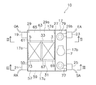
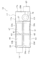
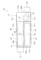
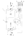
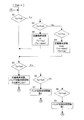
図1〜4に示すように、本実施形態の空気調和機10は、熱交換器の表面にシリカゲル等の吸着剤を担持したデシカント式外調機であって、室内空間に供給される空気に対して冷房除湿運転や暖房加湿運転を行うものであり、中空直方体状のケーシング17を備えている。そして、ケーシング17には、冷媒回路1等が収納されている。
[Basic configuration of the air conditioner 10]
As shown in FIGS. 1 to 4, the
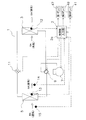
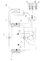
冷媒回路1は、図4に示すように、周波数を変更可能なインバータ圧縮機7と、四路切換弁9と、第1吸着熱交換器3と、電動弁などの膨張弁11と、第2吸着熱交換器5とが順に接続されて閉回路に形成されている。第1吸着熱交換器3および第2吸着熱交換器5は、四路切換弁9によって冷媒の流路を切り換えることによって、凝縮器および蒸発器のいずれか一方の機能を奏する。
さらに、冷媒回路1は、冷媒が回路全体に充填され、冷媒が循環して蒸気圧縮式の冷凍サイクルを行うように構成されている。
第1吸着熱交換器3の一端は、四路切換弁9に接続されている。第1吸着熱交換器3の他端は、膨張弁11を介して第2吸着熱交換器5の一端に接続されている。第2吸着熱交換器5の他端は、四路切換弁9に接続されている。
As shown in FIG. 4, the
Furthermore, the
One end of the first
[吸着熱交換器および吸着剤の構成]
図1〜3に示すように、第1吸着熱交換器3及び第2吸着熱交換器5は、たとえば、クロスフィン式のフィン・アンド・チューブ型熱交換器により構成され、具体的に、長方形板状に形成されたアルミニウム製の多数のフィンと、フィンを貫通する銅製の伝熱管とを有している。フィン及び伝熱管の外表面には、吸着剤が担持されている。吸着剤としては、ゼオライト、シリカゲル、活性炭、親水性または吸水性を有する有機高分子ポリマー系材料、カルボン酸基またはスルホン酸基を有するイオン交換樹脂系材料、感温性高分子等の機能性高分子材料などが採用され得る。
[Configuration of adsorption heat exchanger and adsorbent]
As shown in FIGS. 1-3, the 1st
[圧縮機の構成]
ここでは、周波数変更可能な圧縮機として、インバータ圧縮機が採用されている。インバータ圧縮機は、周波数を変更することにより容量制御(出力の制御)が可能である。
[四路切換弁の構成]
四路切換弁9は、第1のポートP1と第3のポートP3とが連通すると同時に第2のポートP2と第4のポートP4が連通する状態(図4(A)に示す状態)と、第1のポートP1と第4のポートP4とが連通すると同時に第2のポートP2と第3のポートP3とが連通する状態(図4(B)に示す状態)とに切り換え自在に構成されている。そして、この四路切換弁9を切り換えることにより、第1吸着熱交換器3が凝縮器として機能すると同時に第2吸着熱交換器5が蒸発器として機能する第1状態と、第2吸着熱交換器5が凝縮器として機能すると同時に第1吸着熱交換器3が蒸発器として機能する第2状態との切り換えが行われる。
[Compressor configuration]
Here, an inverter compressor is adopted as a compressor capable of changing the frequency. The inverter compressor can perform capacity control (output control) by changing the frequency.
[Configuration of four-way selector valve]
The four-
[空気調和機の内部の詳細構成]
次に、図1〜3に基づいて、空気調和機10の内部構造についてさらに詳細に説明する。なお、ケーシング17は、図1において、下端をケーシング17の正面とし、上端をケーシング17の背面とし、左端をケーシング17の左側面とし、右端をケーシング17の右側面とする。また、ケーシング17は、図2〜3において、上端がケーシング17の上面であり、下端がケーシング17の下面である。
[Detailed configuration inside the air conditioner]
Next, based on FIGS. 1-3, the internal structure of the
ケーシング17は、平面視正方形で、扁平な箱形に形成されている。ケーシング17の左側面板17aには、外気OAを取り入れる第1吸込口19と、リターン空気である室内からの還気RAを取り入れる第2吸込口21とが形成されている。一方、ケーシング17の右側面板17bには、排気EAを室外に排出する第1吹出口23と、空調空気である給気SAを室内に供給する第2吹出口25とが形成されている。
The
ケーシング17の内部には、仕切部材である仕切板27が設けられる。仕切板27によって、ケーシング17の内部には、空気室29aと機器室29bとが形成されている。仕切板27は、ケーシング17の厚さ方向である垂直方向に設けられ、図2〜3において、上端であるケーシング17の上面板17eから下端であるケーシング17の下面板17fに亘って設けられている。さらに、仕切板27は、図1において、下端であるケーシング17の正面板17cから上端であるケーシング17の背面板17dに亘って設けられている。また、仕切板27は、図1において、ケーシング17の中央部よりやや右側に配置されている。
機器室29bには、冷媒回路1における吸着熱交換器3,5を除くインバータ圧縮機7などの機器が配置される共に、第1ファン79および第2ファン77が収納されている。第1ファン79は、第1吹出口23に接続され、第2ファン77は、第2吹出口25に接続されている。
A
In the
ケーシング17の空気室29aには、仕切部材である第1端面板33と第2端面板31と中央の区画板67とが設けられている。第1端面板33と第2端面板31と区画板67とは、ケーシング17の厚さ方向である垂直方向に設けられ、図2〜3に示すように、ケーシング17の上面板17eから下面板17fに亘って設けられている。
The
第1端面板33と第2端面板31とは、図1に示すように、ケーシング17の左側面板17aから仕切板27に亘って設けられている。また、第1端面板33は、図1において、ケーシング17の中央部よりやや上側(背面板17d側)に配置され、第2端面板31は、図1において、ケーシング17の中央部よりやや下側(正面板17c側)に配置されている。
As shown in FIG. 1, the first
区画板67は、図1に示すように、第1端面板33と第2端面板31とに亘って設けられている。
ケーシング17の内部には、第1端面板33と第2端面板31と区画板67と仕切板27とによって、第1熱交換室69が区画形成されている。また、ケーシング17の内部には、第1端面板33と第2端面板31と区画板67とケーシング17の左側面板17aとによって、第2熱交換室73が区画形成されている。つまり、第1熱交換室69は、図1において右側に位置し、第2熱交換室73は、図1において左側に位置し、第1熱交換室69と第2熱交換室73とは、隣接して並行に形成されている。
As shown in FIG. 1, the
A first
また、第1熱交換室69には、第1吸着熱交換器3が配置され、第2熱交換室73には、第2吸着熱交換器5が配置されている。
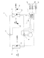
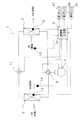
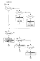
第1端面板33とケーシング17の背面板17dとの間には、仕切部材である水平板61が図2に示すように設けられて、第1流入路63と第1流出路65とが形成される。また、第2端面板31とケーシング17の正面板17cとの間には、仕切部材である水平板55が図3に示すように設けられて第2流入路57と第2流出路59とが形成される。
The first
A
水平板61、55は、ケーシング17の内部空間を、ケーシング17の厚さ方向である垂直方向に上下に仕切っている。そして、図2において、第1流入路63が上面板17e側に、第1流出路65が下面板17f側に形成され、図3において、第2流入路57が上面板17e側に、第2流出路59が下面板17f側に形成されている。
そして、第1流入路63及び第1流出路65と第2流入路57及び第2流出路59とは、図1において、第1熱交換室69及び第2熱交換室73を横断する中央面(正面板17cと背面板17dとの真ん中に位置する仮想面)を基準として面対称に配置されている。
The
And the
第1流入路63は、第1吸込口19に連通している。第1流出路65は、第1ファン79に連通し、第1吹出口23に連通している。第2流入路57は、第2吸込口21に連通している。第2流出路59は、第2ファン77に連通し、第2吹出口25に連通している。
第1端面板33には、図2に示すように、4つの開口33a〜33dが形成されて、各開口33a〜33dには、第1ダンパ47、第2ダンパ49、第3ダンパ51及び第4ダンパ53が設けられている。4つの開口33a〜33dは、行列方向に近接して位置している。つまり、開口33a〜33dは、上下左右に2つずつ升目状に配置され、第1の開口33aと第3の開口33cとが第1熱交換室69に開口し、第2の開口33bと第4の開口33dとが第2熱交換室73に開口している。
The
As shown in FIG. 2, four
第1の開口33aは、第1流入路63と第1熱交換室69とを連通させ、第3の開口33cは、第1流出路65と第1熱交換室69とを連通させている。また、第2の開口33bは、第1流入路63と第2熱交換室73とを連通させ、第4の開口33dは、第1流出路65と第2熱交換室73とを連通させている。
第2端面板31には、図3に示すように、4つの開口31a〜31dが形成されて、各開口31a〜31dには、第5ダンパ35、第6ダンパ37、第7ダンパ39及び第8ダンパ41が設けられている。4つの開口31a〜31dは、行列方向に近接して位置している。つまり、開口31a〜31dは、上下左右に2つずつ升目状に配置され、第5の開口31aと第7の開口31cとが第1熱交換室69に開口し、第6の開口31bと第8の開口31dとが第2熱交換室73に開口している。
第5の開口31aは、第2流入路57と第1熱交換室69とを連通させ、第7の開口31cは、第2流出路59と第1熱交換室69とを連通させている。また、第6の開口31bは、第2流入路57と第2熱交換室73とを連通させ、第8の開口31dは、第2流出路59と第2熱交換室73とを連通させている。
The
As shown in FIG. 3, the second
The
[空気調和機の第1状態、第2状態、および両状態のバッチ切換動作の概略]
本実施の形態の空気調和機10は、図4(A)に示す第1状態のように、凝縮器として機能する第1吸着熱交換器3に室内からの還気RAまたは外気OAを第2空気として取り込んで除湿を行ったのち、室外へ排気EAを排出し、または室内へ給気SAを供給する。それとともに、第1状態では、蒸発器として機能する第2吸着熱交換器5に、外気OAまたは室内からの還気RAを第1空気として取り込んで加湿を行ったのち、室内へ給気SAを供給し、または室外へ排気EAを排出する。
[Outline of batch switching operation of air conditioner in first state, second state, and both states]
As in the first state shown in FIG. 4A, the
そして、所定のバッチ切換時間間隔で、四路切換弁9を切り換えるとともに、ダンパ47〜53、35〜41による空気流路の切り換えを行う。これにより、図4(B)に示す第2状態となる。
この第2状態では、蒸発器として機能する第1吸着熱交換器3に外気OAまたは室内からの還気RAを第1空気として取り込んで加湿を行ったのち、室内へ給気SAを供給し、または室外へ排気EAを排出する。それとともに、第2状態では、凝縮器として機能する第2吸着熱交換器5に室内からの還気RAまたは外気OAを第1空気として取り込んで除湿を行ったのち、室外へ排気EAを排出し、または室内へ給気SAを供給する。
Then, at the predetermined batch switching time interval, the four-
In this second state, after the outside air OA or the return air RA from the room is taken as the first air into the first
このように、本実施形態の空気調和機10は、第1状態と第2状態とを切り換えることで、各吸着熱交換器3,5において吸着動作と再生動作とを交互に行わせることができる。すなわち、各吸着熱交換器3,5では、吸着動作あるいは再生動作というバッチが、所定のバッチ切換時間間隔で切り換えられる。
Thus, the
[空気調和機の除湿運転および加湿運転]
次に、空気調和機10の除湿運転および加湿運転について説明する。
空気調和機10が除湿運転を行う場合には、第1吸着熱交換器3および第2吸着熱交換器5を交互に蒸発器として機能させ、この第1吸着熱交換器3または第2吸着熱交換器5を介して空気調和機10内を流れる空気に含まれる水分を吸着剤で吸着させる。一方、第2吸着熱交換器5または第1吸着熱交換器3を凝縮器として機能させ、凝縮熱により、この第2吸着熱交換器5または第1吸着熱交換器3を介して空気調和機10内を流れる空気に対して吸着剤において吸着した水分を放出して吸着剤を再生させる。そして、吸着剤によって除湿された空気を室内に供給し、かつ吸着剤から水分が放出された空気を室外に放出するように、四路切換弁9によって冷媒回路1の冷媒循環の向きを切り換えるとともに、第1〜第8ダンパ47〜53、35〜41によって空気流路を切り換える。
[Dehumidifying and humidifying operation of air conditioner]
Next, the dehumidifying operation and the humidifying operation of the
When the
空気調和機10が加湿運転を行う場合には、蒸発器として機能する第1吸着熱交換器3または第2吸着熱交換器5の吸熱作用により空気調和機10内を流れる空気に含まれる水分を吸着剤で吸着する。一方、凝縮器として機能する第2吸着熱交換器5または第1吸着熱交換器3の放熱作用により空気調和機10内を流れる空気に対して吸着剤において吸着した水分を放出して吸着剤を再生する。そして、吸着剤からの水分の放出を受けて加湿された空気を室内に供給するように、四路切換弁9によって冷媒回路1の冷媒循環の向きを切り換えるとともに、第1〜第8ダンパ47〜53、35〜41によって空気流路を切り換える。
When the
具体的には、全換気モードにおいて除湿運転を行う場合(除湿換気運転を行う場合)には、外気OAを取り込み、蒸発器として機能する第1吸着熱交換器3または第2吸着熱交換器5の表面に担持された吸着剤において外気OAの水分を吸着し、外気OAを除湿された給気SAとして室内に供給する。一方では、室内からの還気RAを取り込み、凝縮器として機能する第2吸着熱交換器5または第1吸着熱交換器3の表面に担持された吸着剤から水分を放出させて吸着剤を再生し、加湿空気となった還気RAを排気EAとして室外へ放出する。
Specifically, when the dehumidifying operation is performed in the total ventilation mode (when the dehumidifying ventilation operation is performed), the first
また、循環モードにおいて除湿運転を行う場合(除湿循環運転を行う場合)には、室内からの還気RAを取り込み、蒸発器として機能する第1吸着熱交換器3または第2吸着熱交換器5の表面に担持された吸着剤において水分を吸着させ、除湿された還気RAを給気SAとして室内に供給する。一方、吸着剤の再生については、外気OAを取り込み、その外気OAに凝縮器として機能する第2吸着熱交換器5または第1吸着熱交換器3の表面に担持された吸着剤から水分を放出させて吸着剤を再生させ、加湿された外気OAを排気EAとして室外へ放出する。
Further, when the dehumidifying operation is performed in the circulation mode (when the dehumidifying circulation operation is performed), the return air RA from the room is taken in, and the first
また、全換気モードにおいて加湿運転を行う場合(加湿換気運転を行う場合)には、室内からの還気RAを取り込み、蒸発器として機能する第1吸着熱交換器3または第2吸着熱交換器5の表面に担持された吸着剤において取り込まれた空気に含まれる水分を吸着し、除湿された還気RAと排気EAとして室外に排出する。一方では、外気OAを取り込み、凝縮器として機能する第2吸着熱交換器5または第1吸着熱交換器3の表面に担持された吸着剤から水分を放出させて吸着剤を再生し、加湿された外気OAを給気SAとして室内に供給する。
Further, when the humidification operation is performed in the full ventilation mode (when the humidification ventilation operation is performed), the return air RA from the room is taken in, and the first
また、循環モードにおいて加湿運転を行う場合(加湿循環運転を行う場合)には、外気OAを取り込み、蒸発器として機能する第1吸着熱交換器3または第2吸着熱交換器5の表面に担持された吸着剤において取り込まれた外気OAに含まれる水分を吸着させ、除湿された外気OAを排気EAとして屋外へ放出する。一方では、室内からの還気RAを取り込み、凝縮器として機能する第2吸着熱交換器5または第1吸着熱交換器3の表面に担持された吸着剤から水分を放出して吸着剤を再生し、加湿された還気RAを給気SAとして室内に供給する。
Further, when the humidification operation is performed in the circulation mode (when the humidification circulation operation is performed), the outside air OA is taken in and carried on the surface of the first
[制御部による各運転の詳細と空調能力制御]
図5に示すように、本実施形態では、第1吸着熱交換器3の内部における冷媒の温度を測定するために、サーミスタなどの温度センサ12が設けられている。また、第2吸着熱交換器5の内部における冷媒の温度を測定するために、温度センサ13が設けられている。これらの温度センサ12、13は、具体的には、各吸着熱交換器3,5の冷媒を通す伝熱管に接触して伝熱管の温度を測ることで冷媒の温度を測定するものであり、CPUなどからなる制御部2に接続されている。
[Details of each operation and air conditioning capacity control by the control unit]
As shown in FIG. 5, in the present embodiment, a
制御部2は、温度センサ12、13によって検出された第1吸着熱交換器3および第2吸着熱交換器5の冷媒の温度に基づいて、インバータ圧縮機7の周波数の制御による容量制御、およびバッチ切換時間間隔を制御する。また、制御部2は、ユーザやメンテナンスパーソンに入力を行わせるディップスイッチ等の入力部2aを有しており、その入力部2aに入力された優先して処理すべき負荷(潜熱負荷、顕熱負荷、あるいは全熱負荷)が優先して処理されるように、インバータ圧縮機7の容量制御およびバッチ切換時間間隔の制御を行う。なお、全熱負荷とは、潜熱負荷と顕熱負荷との和である。
The
バッチ切換時間間隔の制御は、具体的には、四路切換弁9の切り換え、および第1〜8ダンパ47〜53、35〜41による空気流路と四路切換弁9の切り換えを行う時間間隔であるバッチ切換時間間隔の制御である。
さらに、本実施の形態では、第1吸着熱交換器3および第2吸着熱交換器5の冷媒の温度以外の追加の制御条件として、給気湿度および室内空気の湿度も用いる。給気湿度を測定するための給気湿度センサ14および室内空気の湿度を測定するための室内空気の湿度センサ15も、制御部2に接続されている。
More specifically, the batch switching time interval is controlled by switching the four-
Further, in the present embodiment, the supply air humidity and the humidity of the room air are also used as additional control conditions other than the refrigerant temperatures of the first
以下に、本実施形態の空気調和機10の各運転について詳細に説明し、その後にバッチ切換時間間隔の制御を含む空調能力制御について詳しく説明する。なお、ここでは代表的な運転として、冷房除湿運転や暖房加湿運転を挙げて説明しているが、四路切換弁9の切り換えと第1〜8ダンパ47〜53、35〜41による空気流路の切り換えとの時間をずらしたり、第1〜8ダンパ47〜53、35〜41による空気流路の切り換えを更に細かく制御したりすることによって、冷房加湿運転や暖房加湿運転を行うことも可能である。
Below, each operation | movement of the
<冷房除湿換気運転>
第1状態では、第1ファン79及び第2ファン77を駆動した状態で、四路切換弁9が図5に示す状態に切り換えられている。その結果、凝縮器として機能する第2吸着熱交換器5での吸着剤の再生(脱離)動作と、蒸発器として機能する第1吸着熱交換器3での吸着剤の吸着動作とが行われることになる。つまり、第1状態では、室内からの還気RAを第2吸着熱交換器5に供給し、第2吸着熱交換器5から脱離した水分が換気RAに付与されることによって、加湿された換気RAが排気EAとして室外に排出される。一方では、外気OAが第1吸着熱交換器3に供給され、第1吸着熱交換器3において外気OA中の水分が吸着されて、除湿された外気OAが給気SAとして室内へ供給される。この給気SAは、除湿が為されているとともに、蒸発器として機能する第1吸着熱交換器3によって冷却されている。
<Cooling and dehumidification ventilation operation>
In the first state, the four-
つまり、インバータ圧縮機7から吐出された高温高圧の冷媒は、加熱用の熱媒体として第2吸着熱交換器5に流れ、第2吸着熱交換器5の外表面に担持された吸着剤が加熱される。この加熱によって吸着剤から水分が脱離し、第2吸着熱交換器5の吸着剤が再生される。
一方、第2吸着熱交換器5で凝縮した冷媒は、膨張弁11で減圧される。減圧後の冷媒は、冷却用の熱媒体として第1吸着熱交換器3に流れる。この第1吸着熱交換器3において、第1吸着熱交換器3の外表面に担持された吸着剤が外気OA中の水分を吸着する際に吸着熱が発生する。第1吸着熱交換器3の冷媒は、この吸着熱や外気OAの熱を吸熱して蒸発する。蒸発した冷媒は、インバータ圧縮機7に戻って圧縮される。
That is, the high-temperature and high-pressure refrigerant discharged from the
On the other hand, the refrigerant condensed in the second
この第1状態において上記の動作を所定のバッチ切換時間間隔だけ行った後、第2状態に切り換えられる。
第2状態では、第1ファン79及び第2ファン77を駆動した状態で、四路切換弁9が、図5に示す状態(すなわち、インバータ圧縮機7から第2吸着熱交換器5へ冷媒を圧送する状態)から、インバータ圧縮機7から第1吸着熱交換器3へ冷媒を圧送する状態へと切り換えられている。また、ダンパ47〜53ならびにダンパ35〜41による空気流路の切り換えにより、室内からの還気RAが第1吸着熱交換器3へ供給され、外気OAが第2吸着熱交換器5へ供給されるようになっている。
In this first state, the above operation is performed for a predetermined batch switching time interval, and then the second state is switched.
In the second state, with the
その結果、第2状態では、室内からの還気RAが第1吸着熱交換器3に供給され、第1吸着熱交換器3の吸着剤から脱離した水分が換気RAに放出されて、加湿された換気RAが排気EAとして排出される。一方では、外気OAが第2吸着熱交換器5に供給され、取り込まれた外気OA中の水分が第2吸着熱交換器5の吸着剤に吸着されることによって、除湿された外気OAが給気SAとして室内へ供給される。この給気SAは、除湿が為されているとともに、蒸発器として機能する第2吸着熱交換器5によって冷却されている。
As a result, in the second state, the return air RA from the room is supplied to the first
つまり、インバータ圧縮機7から吐出された高温高圧の冷媒は、加熱用の熱媒体として第1吸着熱交換器3に流れ、第1吸着熱交換器3の外表面に担持された吸着剤が加熱される。この加熱によって吸着剤から水分が脱離し、第1吸着熱交換器3の吸着剤が再生される。
一方、第1吸着熱交換器3で凝縮した冷媒は、膨張弁11で減圧される。減圧後の冷媒は、冷却用の熱媒体として第2吸着熱交換器5に流れる。この第2吸着熱交換器5において、第2吸着熱交換器5の外表面に担持された吸着剤が外気OA中の水分を吸着する際に吸着熱が発生する。第2吸着熱交換器5の冷媒は、この吸着熱や外気OAの熱を吸熱して蒸発する。蒸発した冷媒は、インバータ圧縮機7に戻って圧縮される。
以上のような第1状態および第2状態を所定のバッチ切換時間間隔で交互に切り換えることにより、冷房除湿および換気が連続的に行われる。
That is, the high-temperature and high-pressure refrigerant discharged from the
On the other hand, the refrigerant condensed in the first
By alternately switching the first state and the second state as described above at predetermined batch switching time intervals, cooling dehumidification and ventilation are continuously performed.
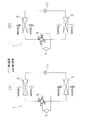
<冷房除湿循環運転>
上述の冷房除湿換気運転と比較して、基本的な熱交換器の吸着動作および再生動作は同じであるが、図6に示すように、外気OAを取り込んで凝縮器として機能する第2吸着熱交換器5(または第1吸着熱交換器3)に供給し再び排気EAとして室外に排出するとともに、室内から取り込んだ還気RAを蒸発器として機能する第1吸着熱交換器3(または第2吸着熱交換器5)に供給し再び室内に給気SAとして供給する点で異なる。すなわち、室内に供給される給気SAは、室内から取り込まれた換気RAを除湿・冷却したものとなり、外気OAの室内への供給は行われない。
<Cooling and dehumidification circulation operation>
Compared with the above-mentioned cooling and dehumidifying ventilation operation, the basic adsorption operation and regeneration operation of the heat exchanger are the same, but as shown in FIG. 6, the second adsorption heat that takes in the outside air OA and functions as a condenser. The first adsorption heat exchanger 3 (or the second adsorption heat exchanger 3) is supplied to the exchanger 5 (or the first adsorption heat exchanger 3) and discharged again as exhaust EA, and the return air RA taken in from the room functions as an evaporator. It is different in that it is supplied to the adsorption heat exchanger 5) and supplied again into the room as the supply air SA. That is, the supply air SA supplied to the room is obtained by dehumidifying and cooling the ventilation RA taken from the room, and the supply of the outside air OA to the room is not performed.
<暖房加湿換気運転>
第1状態では、図7に示すように、外気OAを取り込んで第2吸着熱交換器5に供給し、第2吸着熱交換器5の吸着剤から脱離した水分が付与された外気OA(加湿空気)が、給気SAとして室内へ供給される。一方では、室内から取り込んだ還気RAが第1吸着熱交換器3に供給され、第1吸着熱交換器3の吸着剤に還気RA中の水分が吸着される。このようにして除湿された還気RAは、排気EAとして室外に排出される。この給気SAは、加湿されるとともに、凝縮器として機能する第2吸着熱交換器5によって加熱される。
<Heating humidification ventilation operation>
In the first state, as shown in FIG. 7, the outside air OA is taken in and supplied to the second
この第1状態において上記の動作を所定のバッチ切換時間間隔だけ行った後、第2状態に切り換えられる。
第2状態では、第1ファン79及び第2ファン77を駆動した状態で、四路切換弁9が、図7に示す状態(すなわち、インバータ圧縮機7から第2吸着熱交換器5へ冷媒を圧送する状態)から、インバータ圧縮機7から第1吸着熱交換器3へ冷媒を圧送する状態へ切り換えられている。また、ダンパ47〜53ならびにダンパ35〜41による空気流路の切り換えにより、室内からの還気RAが第2吸着熱交換器5へ供給され、外気OAが第1吸着熱交換器3へ供給されるようになっている。
In this first state, the above operation is performed for a predetermined batch switching time interval, and then the second state is switched.
In the second state, with the
その結果、第2状態では、第1吸着熱交換器3の吸着剤から脱離した水分が外気OAに付与されることによって、加湿された外気OAが給気SAとして室内へ供給される。一方では、第2吸着熱交換器5の吸着剤に還気RAの水分が吸着されることによって、除湿された還気RAが排気EAとして排出される。また、給気SAは、凝縮器として機能する第1吸着熱交換器3によって加熱されている。
以上のような第1状態および第2状態を所定のバッチ切換時間間隔で交互に切り換えることにより、暖房加湿および換気が連続的に行われる。
As a result, in the second state, moisture desorbed from the adsorbent of the first
By alternately switching the first state and the second state as described above at predetermined batch switching time intervals, heating humidification and ventilation are continuously performed.
<暖房加湿循環運転>
上述の暖房加湿換気運転と比較して、基本的な熱交換器の吸着動作および再生動作は同じであるが、図8に示すように、外気OAを取り込んで蒸発器として機能する第1吸着熱交換器3(または第2吸着熱交換器5)に供給し再び排気EAとして室外に排出するとともに、室内から取り込んだ還気RAを凝縮器として機能する第2吸着熱交換器5(または第1吸着熱交換器3)に供給し再び室内に給気SAとして供給する点で異なる。すなわち、室内に供給される給気SAは、室内から取り込まれた換気RAを加湿・暖房したものとなり、外気OAの室内への供給は行われない。
<Heating humidification circulation operation>
Compared with the above-mentioned heating / humidification / ventilation operation, the basic adsorption operation and regeneration operation of the heat exchanger are the same, but as shown in FIG. 8, the first adsorption heat that takes in outside air OA and functions as an evaporator. The second adsorption heat exchanger 5 (or the first adsorption heat exchanger 5) is supplied to the exchanger 3 (or the second adsorption heat exchanger 5) and discharged again as exhaust EA, and the return air RA taken in from the room functions as a condenser. It is different in that it is supplied to the adsorption heat exchanger 3) and supplied again into the room as the supply air SA. That is, the supply air SA supplied to the room is obtained by humidifying and heating the ventilation RA taken in from the room, and the outside air OA is not supplied to the room.
<空調能力制御>
次に、空調能力制御、すなわち、インバータ圧縮機7の容量制御およびバッチ切換時間間隔の変更制御について説明する。インバータ圧縮機7の容量制御は、具体的にはインバータ圧縮機7の圧縮機周波数を変えることによって行われ、潜熱負荷を処理する潜熱能力の制御を含む全熱能力の制御となる。また、バッチ切換時間間隔の変更制御は、主として、潜熱負荷を処理する潜熱能力と顕熱負荷を処理する顕熱能力との比である顕潜熱能力比の制御となる。
<Air conditioning capacity control>
Next, air conditioning capacity control, that is, capacity control of the
本実施の形態では、制御部2が、空気調和機10が上述のいずれかの運転を行うときに、蒸発器および凝縮器として機能する第1吸着熱交換器3および第2吸着熱交換器5における蒸発器温度や凝縮器温度に基づいて、インバータ圧縮機7の容量制御およびバッチ切換時間間隔の変更制御を行う。また、制御部2は、制御目標として蒸発器温度や凝縮器温度を用いることに加えて、室内空気の湿度、給気SAの湿度、および給気SAの温度のうち1又は複数のパラメータを制御目標としてもよい。
In the present embodiment, when the
まず、凝縮器温度あるいは蒸発器温度を制御目標としたインバータ圧縮機7の容量制御およびバッチ切換時間間隔の変更制御について説明する。
凝縮器温度を制御目標として圧縮機周波数を制御する場合、凝縮器温度が目標値より低い時には圧縮機周波数を上昇させ、目標値より高い時には圧縮機周波数を下降させる。また、凝縮器温度を制御目標としてバッチ切換時間間隔を制御する場合、凝縮器温度が目標値より低い時にはバッチ切換時間間隔を短くし、凝縮器温度が目標値より高い時にはバッチ切換時間間隔を長くする。
First, capacity control of the
When the compressor frequency is controlled using the condenser temperature as a control target, the compressor frequency is increased when the condenser temperature is lower than the target value, and the compressor frequency is decreased when the condenser temperature is higher than the target value. Also, when controlling the batch switching time interval with the condenser temperature as the control target, shorten the batch switching time interval when the condenser temperature is lower than the target value, and lengthen the batch switching time interval when the condenser temperature is higher than the target value. To do.
蒸発器温度を制御目標として圧縮機周波数を制御する場合、蒸発器温度が目標値より低い時には圧縮機周波数を下降させ、目標値より高い時には圧縮機周波数を上昇させる。また、バッチ切換時間間隔を制御する場合、蒸発器温度が目標値より低い時にはバッチ切換時間間隔を長くし、蒸発器温度が目標値より高い時にはバッチ切換時間間隔を短くする。
さらに、凝縮器温度と蒸発器温度との組合せを制御目標にして、圧縮機周波数およびバッチ切換時間間隔を同時に制御することも可能である。
When the compressor frequency is controlled using the evaporator temperature as a control target, the compressor frequency is decreased when the evaporator temperature is lower than the target value, and the compressor frequency is increased when the evaporator temperature is higher than the target value. When controlling the batch switching time interval, the batch switching time interval is lengthened when the evaporator temperature is lower than the target value, and the batch switching time interval is shortened when the evaporator temperature is higher than the target value.
Furthermore, it is also possible to control the compressor frequency and the batch switching time interval simultaneously with the combination of the condenser temperature and the evaporator temperature as a control target.
次に、凝縮器温度と蒸発器温度との2つの制御目標を用いて空調能力制御を行う場合の制御例について、図9を参照して説明する。この制御は、冷房除湿運転においても暖房加湿運転においても用いられる。
ここでは、凝縮器温度Tcを第1目標とし、蒸発器温度Teを第2目標とした制御が行われる。図9に示すように、まず、現在の凝縮器温度Tcを目標の凝縮器温度Tc0と比較し(ステップS1およびステップS2)、Tc=Tc0の場合はステップS5へスキップし、Tc<Tc0の場合には、圧縮機周波数を上げる(ステップS3)。これにより、現在の凝縮器温度Tcが上昇し、現在の蒸発器温度Teが下降する。一方、Tc>Tc0の場合には、圧縮機周波数を下げる(ステップS4)。これにより、現在の凝縮器温度Tcが下降し、現在の蒸発器温度Teが上昇する
その後、ステップS5において、現在の蒸発器温度Teと目標の蒸発器温度Te0との比較が行われる(ステップS5およびステップS6)。Te=Te0の場合は、圧縮機周波数およびバッチ切換時間間隔をともに操作しないでスタートに戻る。Te<Te0の場合には、バッチ切換時間間隔を長くし(ステップS7)、その後スタートに戻る。バッチ切換時間間隔を長くすると、凝縮器温度Tcおよび蒸発器温度Teがともに上昇する。
Next, a control example in the case of performing air conditioning capability control using two control targets of the condenser temperature and the evaporator temperature will be described with reference to FIG. This control is used in both the cooling and dehumidifying operation and the heating and humidifying operation.
Here, control is performed with the condenser temperature Tc as the first target and the evaporator temperature Te as the second target. As shown in FIG. 9, first, the current condenser temperature Tc is compared with the target condenser temperature Tc0 (steps S1 and S2). If Tc = Tc0, the process skips to step S5, and Tc <Tc0. The compressor frequency is increased (step S3). As a result, the current condenser temperature Tc rises and the current evaporator temperature Te falls. On the other hand, if Tc> Tc0, the compressor frequency is lowered (step S4). As a result, the current condenser temperature Tc decreases and the current evaporator temperature Te increases. Thereafter, in step S5, the current evaporator temperature Te is compared with the target evaporator temperature Te0 (step S5). And step S6). When Te = Te0, the operation returns to the start without operating both the compressor frequency and the batch switching time interval. If Te <Te0, the batch switching time interval is lengthened (step S7), and then the process returns to the start. Increasing the batch switching time interval increases both the condenser temperature Tc and the evaporator temperature Te.
一方、Te>Te0の場合(ステップS8)には、バッチ切換時間間隔を短くし(ステップS9)、その後スタートに戻る。
なお、ここでは、各吸着熱交換器3,5において吸着動作あるいは再生動作というバッチが所定のバッチ切換時間間隔で切り換えられるため、凝縮器温度Tcや蒸発器温度Teは、バッチごとの代表値またはバッチの間を通じての平均代表値になる。
On the other hand, when Te> Te0 (step S8), the batch switching time interval is shortened (step S9), and then the process returns to the start.
Here, since the batch of the adsorption operation or the regeneration operation is switched at a predetermined batch switching time interval in each of the
また、この例では、蒸発器温度Teを目標の蒸発器温度Te0に合わせるためにバッチ切換時間間隔を操作(ステップS6〜S9)したのち、再度凝縮器温度Tcを調整するために圧縮機を操作し(ステップS1〜S4)、さらにTeの調整のためにバッチ切換時間間隔を操作(ステップS6〜S9)する。図9に示す制御フローでは、このような操作の繰り返しが行われることが考えられるが、必ずしもTc=Tc0且つTe=Te0に収束しなくても操作上は問題がない。 Also, in this example, after adjusting the batch switching time interval (steps S6 to S9) to adjust the evaporator temperature Te to the target evaporator temperature Te0, the compressor is operated to adjust the condenser temperature Tc again. (Steps S1 to S4), and further, the batch switching time interval is operated (Steps S6 to S9) to adjust Te. In the control flow shown in FIG. 9, it is conceivable that such an operation is repeated, but there is no problem in operation even if Tc = Tc0 and Te = Te0 do not converge.
次に、凝縮器温度と室内空気の湿度との2つの制御目標を用いて空調能力制御を行う場合の制御例について、図10および図11を参照して説明する。冷房除湿運転を行うときには図10のフローチャートの制御が採られ、暖房加湿運転を行うときには図11のフローチャートの制御が採られる。
ここでは、凝縮器温度Tcを第1目標とし、室内空気の湿度Hraを第2目標とした制御が行われる。
Next, a control example in the case of performing air conditioning capability control using two control targets of the condenser temperature and the indoor air humidity will be described with reference to FIGS. 10 and 11. When performing the cooling and dehumidifying operation, the control of the flowchart of FIG. 10 is employed, and when performing the heating and humidifying operation, the control of the flowchart of FIG. 11 is employed.
Here, control is performed with the condenser temperature Tc as the first target and the indoor air humidity Hra as the second target.
冷房除湿運転時の制御では、圧縮機周波数を上げると、凝縮器温度Tcは上がり、室内空気の湿度Hraは下がる。また、バッチ切換時間間隔を長くすると、凝縮器温度Tcおよび室内空気の湿度Hraが両方とも上がる。
まず、現在の凝縮器温度Tcを目標の凝縮器温度Tc0と比較し(ステップS11およびステップS12)、Tc=Tc0の場合はステップS15へスキップし、Tc<Tc0の場合には、圧縮機周波数を上げる(ステップS13)。このとき、現在の凝縮器温度Tcは上昇し、現在の室内空気の湿度Hraは下降する。一方、Tc>Tc0の場合には、圧縮機周波数を下げる(ステップS14)。このとき、現在の凝縮器温度Tcは下降し、現在の室内空気の湿度Hraは上昇する。
In the control during the cooling and dehumidifying operation, when the compressor frequency is increased, the condenser temperature Tc is increased, and the indoor air humidity Hra is decreased. Further, when the batch switching time interval is lengthened, both the condenser temperature Tc and the indoor air humidity Hra are increased.
First, the current condenser temperature Tc is compared with the target condenser temperature Tc0 (steps S11 and S12). If Tc = Tc0, the process skips to step S15. If Tc <Tc0, the compressor frequency is set. (Step S13). At this time, the current condenser temperature Tc rises and the current indoor air humidity Hra falls. On the other hand, if Tc> Tc0, the compressor frequency is lowered (step S14). At this time, the current condenser temperature Tc decreases, and the current indoor air humidity Hra increases.
その後、現在の室内空気の湿度Hraと目標の室内空気の湿度Hra0とを比較する(ステップS15およびステップS16)。Hra=Hra0の場合は、圧縮機周波数およびバッチ切換時間間隔をともに操作しないでスタートに戻る。Hra<Hra0の場合には、バッチ切換時間間隔を長くし(ステップS17)、その後スタートに戻る。バッチ切換時間間隔を長くすると、凝縮器温度Tcおよび室内空気の湿度Hraがともに上昇する。一方、Hra>Hra0の場合(ステップS18)には、バッチ切換時間間隔を短くし(ステップS19)、その後スタートに戻る。 Thereafter, the current indoor air humidity Hra is compared with the target indoor air humidity Hra0 (steps S15 and S16). When Hra = Hra0, the operation returns to the start without operating both the compressor frequency and the batch switching time interval. If Hra <Hra0, the batch switching time interval is lengthened (step S17), and then the process returns to the start. Increasing the batch switching time interval increases both the condenser temperature Tc and the indoor air humidity Hra. On the other hand, if Hra> Hra0 (step S18), the batch switching time interval is shortened (step S19), and then the process returns to the start.
暖房加湿運転の制御では、冷房除湿運転の制御と同様に、凝縮器温度Tcを第1目標とし、室内空気の湿度Hraを第2目標とした制御が行われる。
また、暖房加湿運転の制御では、圧縮機周波数を上げると、凝縮器温度Tcおよび室内空気の湿度Hraが両方とも上がる。一方、バッチ切換時間間隔を長くすると、凝縮器温度Tcは上がり、室内空気の湿度Hraは下がる。
In the control of the heating and humidifying operation, the control is performed with the condenser temperature Tc as the first target and the humidity Hra of the room air as the second target, as in the control of the cooling and dehumidifying operation.
In the control of the heating and humidifying operation, when the compressor frequency is increased, both the condenser temperature Tc and the indoor air humidity Hra are increased. On the other hand, when the batch switching time interval is lengthened, the condenser temperature Tc rises and the indoor air humidity Hra falls.
ここでは、まず、現在の凝縮器温度Tcを目標の凝縮器温度Tc0と比較し(ステップS21およびステップS22)、Tc=Tc0の場合はステップS25へスキップし、Tc<Tc0の場合には、圧縮機周波数を上げる(ステップS23)。このとき、現在の凝縮器温度Tcおよび現在の室内空気の湿度Hraは、両方とも上昇する。一方、Tc>Tc0の場合には、圧縮機周波数を下げる(ステップS24)。このとき、現在の凝縮器温度Tcおよび現在の室内空気の湿度Hraは、両方とも下降する
その後、現在の室内空気の湿度Hraと目標の室内空気の湿度Hra0とを比較する(ステップS25およびステップS26)。Hra=Hra0の場合は、圧縮機周波数およびバッチ切換時間間隔をともに操作しないでスタートに戻る。Hra<Hra0の場合には、バッチ切換時間間隔を短くし(ステップS27)、その後スタートに戻る。
一方、Hra>Hra0の場合(ステップS28)には、バッチ切換時間間隔を長くし(ステップS29)、その後スタートに戻る。バッチ切換時間間隔を長くすると、凝縮器温度Tcは上昇し、室内空気の湿度Hraは下降する。
Here, first, the current condenser temperature Tc is compared with the target condenser temperature Tc0 (steps S21 and S22). If Tc = Tc0, the process skips to step S25, and if Tc <Tc0, the compression is performed. The machine frequency is increased (step S23). At this time, both the current condenser temperature Tc and the current indoor air humidity Hra rise. On the other hand, if Tc> Tc0, the compressor frequency is lowered (step S24). At this time, the current condenser temperature Tc and the current indoor air humidity Hra both decrease. Thereafter, the current indoor air humidity Hra and the target indoor air humidity Hra0 are compared (steps S25 and S26). ). When Hra = Hra0, the operation returns to the start without operating both the compressor frequency and the batch switching time interval. If Hra <Hra0, the batch switching time interval is shortened (step S27), and then the process returns to the start.
On the other hand, if Hra> Hra0 (step S28), the batch switching time interval is lengthened (step S29), and then the process returns to the start. When the batch switching time interval is lengthened, the condenser temperature Tc rises and the indoor air humidity Hra falls.
<初期入力設定に基づく空調能力制御>
空調能力制御、すなわち、インバータ圧縮機7の容量制御およびバッチ切換時間間隔の変更制御については、上記のように、蒸発器温度や凝縮器温度、さらには室内空気の湿度、給気SAの湿度、および給気SAの温度などを適宜組み合わせて制御目標を決めて行っているが、以下のような初期入力設定に基づく条件も加味される。
<Air conditioning capacity control based on initial input settings>
As described above, the air conditioning capacity control, that is, the capacity control of the
制御部2の入力部2aには、ユーザなどによって、優先して処理すべき負荷(潜熱負荷、顕熱負荷、あるいは全熱負荷)が入力されていることがある。この場合には、そこで入力された負荷によって、インバータ圧縮機7の容量制御およびバッチ切換時間間隔の制御が以下のように影響を受けることになる。
まず、入力された優先して処理すべき負荷が潜熱負荷である場合には、バッチ切換時間間隔の変更制御による潜熱負荷の処理量の変更を、インバータ圧縮機7の容量制御による潜熱負荷の処理量の変更よりも優先させる。
A load (latent heat load, sensible heat load, or total heat load) to be preferentially processed may be input to the
First, when the input load to be preferentially processed is a latent heat load, the change of the processing amount of the latent heat load by the batch switching time interval change control is changed to the processing of the latent heat load by the capacity control of the
また、入力された優先して処理すべき負荷が顕熱負荷である場合にも、バッチ切換時間間隔の変更制御による顕熱負荷の処理量の変更を、インバータ圧縮機7の容量制御による顕熱負荷の処理量の変更よりも優先させる。
また、入力された優先して処理すべき負荷が全熱負荷である場合には、まずバッチ切換時間間隔の制御により潜熱負荷の処理量と顕熱負荷の処理量との比である顕潜熱処理量比を固定し、その後にインバータ圧縮機7の容量制御を行う。
Even when the input load to be preferentially processed is a sensible heat load, the change in the amount of sensible heat load by the change control of the batch switching time interval is changed to the sensible heat by the capacity control of the
If the input load to be preferentially processed is the total heat load, first, the sensible latent heat treatment, which is the ratio of the latent heat load throughput to the sensible heat load throughput, is controlled by the batch switching time interval. The quantity ratio is fixed, and then the capacity control of the
[本実施形態の空気調和機の特徴]
(1)
本実施形態の空気調和機10では、第1吸着熱交換器3および第2吸着熱交換器5が交互に凝縮器および蒸発器として機能する。そして、潜熱能力に直接影響する吸着剤の温度が、給気SAの温度や室内の空気温度よりも、凝縮器および蒸発器の冷媒温度により追随することに着目して、空気調和機10の能力制御(圧縮機7の容量制御およびバッチ切換時間間隔の変更制御)における制御目標として、従来のように再生空気温度などを用いる代わりに、ここでは蒸発器温度や凝縮器温度を用いている。
[Features of the air conditioner of this embodiment]
(1)
In the
このため、従来よりも適切な除加湿時の潜熱能力制御(除加湿水分量の制御)および除加湿時の顕潜熱処理量比の制御ができるようになっている。
(2)
本実施形態の空気調和機10では、第1および第2吸着熱交換器3,5が表面に吸着剤を担持しており、吸着剤の温度は非常に強く冷媒温度に連動することになる。したがって、蒸発器温度や凝縮器温度を制御目標として空気調和機10の能力制御を行うことは、非常に効果的になっている。
For this reason, it is possible to control the latent heat capacity control during dehumidification / humidification (control of the dehumidified / humidified moisture content) and control of the sensible latent heat treatment amount ratio during dehumidification / humidification more appropriately than in the past.
(2)
In the
(3)
また、空気調和機10では、凝縮器温度を第1目標、蒸発器温度を第2目標として能力制御を行ったり、凝縮器温度や蒸発器温度を第1目標、室内空気の湿度、給気SAの湿度、および給気SAの温度のうち1又は複数のパラメータを第2目標として能力制御を行ったりすることができ、凝縮器温度や蒸発器温度だけにより空気調和機10の能力制御を行う場合に較べて更に適切な能力制御が可能となる。
(3)
Further, in the
(4)
空気調和機10では、蒸発器として働く吸着熱交換器3,5によって吸着剤が吸着動作を行い、また凝縮器として働く吸着熱交換器5,3によって吸着剤が再生動作を行う。そして、吸着剤の吸着動作と再生動作との切り換えの時間間隔(バッチ切換時間間隔)の変更制御が、インバータ圧縮機7の容量制御とともに、制御部2によって行われている。
(4)
In the
バッチ切換時間間隔の変更をすると、空気調和機10の潜熱処理能力と顕熱処理能力との比である顕潜熱処理量比を変えることができる。一方、インバータ圧縮機7の容量制御を行うと、潜熱処理能力および顕熱処理能力の和である全熱処理能力を増減することができる。すなわち、制御部2は、潜熱処理能力、顕熱処理能力、および全熱処理能力を、それぞれ調整することができる。
When the batch switching time interval is changed, the sensible and latent heat treatment amount ratio, which is the ratio between the latent heat treatment capability and the sensible heat treatment capability of the
そして、そのような調整機能を持つ制御部2は、ユーザなどが入力部2aにおいて入力した負荷(全熱負荷、潜熱負荷、あるいは顕熱負荷)が優先して処理されるように、インバータ圧縮機7の容量制御およびバッチ切換時間間隔の変更制御を行っている。このような制御が為されるため、本空気調和機10では、適切な能力制御をすることができるとともに、ユーザに対して、そのユーザの好みに応じた空調環境を提供することができる。
And the
具体的には、優先して処理すべき負荷が潜熱負荷である場合には、バッチ切換時間間隔の変更制御による潜熱負荷の処理量の変更を、インバータ圧縮機7の容量制御による潜熱負荷の処理量の変更よりも優先させている。すなわち、ここでは、潜熱負荷を優先して処理する場合に、まずバッチ切換時間間隔の変更制御を行って潜熱負荷の処理量を変化させ、それでも足りないときに、インバータ圧縮機7の容量制御を行って潜熱負荷の処理量をさらに変化させている。このように、まずバッチ切換時間間隔の変更制御を行うため、潜熱負荷の処理量を増加させる必要がある場合にも、インバータ圧縮機7の容量を上げる制御によって消費電力量を大幅に増加させることなく潜熱負荷の処理量を増やすことができるようになっている。例えば、バッチ切換時間間隔の変更制御によって潜熱負荷の処理量の顕熱負荷の処理量に対する比を大きくすることで必要な潜熱負荷の処理量が確保できる場合には、インバータ圧縮機7の容量を上げる必要はない。
Specifically, when the load to be preferentially processed is the latent heat load, the change of the processing amount of the latent heat load by the change control of the batch switching time interval is changed to the processing of the latent heat load by the capacity control of the
また、優先して処理すべき負荷が顕熱負荷である場合にも、バッチ切換時間間隔の変更制御による顕熱負荷の処理量の変更を、インバータ圧縮機7の容量制御による顕熱負荷の処理量の変更よりも優先させている。すなわち、ここでは、顕熱負荷を優先して処理する場合に、まずバッチ切換時間間隔の変更制御を行って顕熱負荷の処理量を変化させ、それでも足りないときに、インバータ圧縮機7の容量制御を行って顕熱負荷の処理量をさらに変化させる。このように、まずバッチ切換時間間隔の変更制御を行うため、顕熱負荷の処理量を増加させる必要がある場合にも、インバータ圧縮機7の容量を上げる制御によって消費電力量を大幅に増加させることなく顕熱負荷の処理量を増やすことができるようになる。例えば、バッチ切換時間間隔の変更制御によって顕熱負荷の処理量の潜熱負荷の処理量に対する比を大きくすることで必要な顕熱負荷の処理量が確保できる場合には、インバータ圧縮機7の容量を上げる必要はない。
Further, even when the load to be preferentially processed is the sensible heat load, the change of the processing amount of the sensible heat load by the change control of the batch switching time interval is changed to the processing of the sensible heat load by the capacity control of the
また、優先して処理すべき負荷が全熱負荷である場合には、まずバッチ切換時間間隔の制御により顕潜熱処理量比を固定し、その後にインバータ圧縮機7の容量制御を行っている。これは、全熱負荷を優先させる場合、基本的には顕潜熱処理量比を変える必要がないため、顕潜熱処理量比をまず固定した上でインバータ圧縮機7の容量制御を行っているものである。ここでは、不要な顕潜熱処理量比の変化が抑えられている。より具体的に説明すると、吸着剤の吸着動作と再生動作とを切り換える方式の空気調和機10において全熱負荷の中の顕潜熱負荷の比に合わせて顕潜熱処理量比を調整していくことは、能力制御が徒に複雑化してしまうことにつながる恐れが高い。しかし、ここでは、顕潜熱処理量比を固定してまず全熱負荷の処理量を変化させていき、顕熱または潜熱の負荷と顕熱または潜熱の処理量とがある程度均衡した時点から、残る顕熱負荷または潜熱負荷の処理量を顕潜熱処理量比の調整によって変化させることができる。したがって、制御をシンプル化することができている。
When the load to be preferentially processed is the total heat load, the sensible and latent heat treatment amount ratio is first fixed by controlling the batch switching time interval, and then the capacity control of the
なお、全熱負荷の中の顕潜熱負荷の比に合わせて顕潜熱処理量比を調整していくことが能力制御の複雑化につながる理由は、次のとおりである。空気調和機10では、負荷を処理する室内の空気の温度(顕熱)および湿度(潜熱)を回収して利用する方式を採っているため、処理する空気の状態の影響が直接的に顕熱処理量や潜熱処理量に個別に現れる。したがって、空気調和機10や他の空気調和機の運転により顕潜熱処理量比が逐次変化していき、それにつれて空気調和機10の顕潜熱処理量も逐次変化していくため、最初に顕潜熱処理量比を決めたとしても、処理する空気の温湿度条件が変化すると必要な処理量も変化して、好ましい顕潜熱処理量比が変化していく。このように、顕潜熱処理量比の変更は、現時点における必要な潜熱、顕熱の各処理量の比から調整して行うことが望ましく、インバータ圧縮機7の容量制御により全熱処理量を増減させている最中であって顕潜熱処理量も逐次変化しているときに行うことは、制御の複雑化につながり望ましくない。
The reason why adjusting the sensible / latent heat treatment amount ratio in accordance with the ratio of the sensible / latent heat load in the total heat load leads to complicating the ability control is as follows. The
[他の実施形態]
以上、本発明の一実施形態について説明したが、本発明は実施形態に限定されるものではなく、発明の要旨を逸脱しない範囲で種々の変更が可能である。
(1)
上記実施形態では、空気調和機10の能力制御を行う際の制御目標として凝縮器温度や蒸発器温度を用いているが、凝縮器圧力や蒸発器圧力を制御目標としても、同様に従来よりも適切な空気調和機10の能力制御ができる。
[Other Embodiments]
As mentioned above, although one Embodiment of this invention was described, this invention is not limited to Embodiment, A various change is possible in the range which does not deviate from the summary of invention.
(1)
In the above embodiment, the condenser temperature and the evaporator temperature are used as the control targets when the capacity control of the
(2)
上記実施形態の構成に加え、図12に示すように、吸着材を有さず顕熱処理を主として行う顕熱熱交換器16と膨張弁18とを設けて、顕熱処理能力を向上させてもよい。このような構成の空気調和機であっても、吸着熱交換器3,5の吸着剤の温度が冷媒温度に強く追随することに変わりはないので、凝縮器温度や蒸発器温度あるいは凝縮器圧力や蒸発器圧力を制御目標として空気調和機の能力制御を適切に行うことができる。
(2)
In addition to the configuration of the above embodiment, as shown in FIG. 12, the sensible heat treatment capability may be improved by providing a
(3)
上記実施形態では、吸着剤が第1吸着熱交換器3および第2吸着熱交換器5の表面に担持されているが、本発明はこれに限定されるものではない。例えば、特開2004−69257号公報に記載されているような調湿装置(空気調和機)に対して本発明を適用することも可能である。
(3)
In the said embodiment, although adsorption agent is carry | supported on the surface of the 1st
図13(A),(B)に示す空気調和機110では、吸着剤を有する調湿エレメント181,182が、吸着剤を再生させるための再生熱交換器105とは離れて配置されている。調湿エレメント181,182は、長方形の平板状の平板部材と波形状の波板部材とを交互に積層して構成され、調湿側通路と冷却側通路とが平板部材を挟んで交互に区画形成されて構成されたものである。調湿側通路に設けられた波板部材の表面には、無機多孔質材料と感温性有機系高分子材料からなる吸着剤が担持されている。
In the
空気調和機110は、排気ファン108aおよび給気ファン108bを駆動させて第1の調湿エレメント181で還気RAを除湿するとともに第2の調湿エレメント182を外気OAで再生する第1状態と、第1の調湿エレメント181を外気OAで再生するとともに第2の調湿エレメント182で還気RAを除湿する第2状態とを交互に行う。そして、空気調和機110は、調湿エレメント181、182で加湿された外気OAを室内へ供給する。なお、調湿エレメント181、182で除湿した外気OAや還気RAを給気SAとして室内に供給して除湿運転を行うことも可能であるが、ここでは加湿運転について説明する。
The
加湿運転時において、排気ファン108aおよび給気ファン108bを駆動すると、外気OAがケーシング内に取り込まれるとともに、還気RAがケーシング内に取り込まれる。また、加湿運転時において、圧縮機101により冷凍サイクルが生じる冷媒回路では、再生熱交換器105が凝縮器となり、熱交換器107が蒸発器となる。
加湿運転の第1動作について、図13(A)を参照しながら説明する。この第1動作では、第1の調湿エレメント181についての吸着動作と、第2の調湿エレメント182についての再生動作とが行われる。つまり、第1動作では、第2の調湿エレメント182で空気が加湿され、第1の調湿エレメント181の吸着剤が水分を吸着する。ケーシングに取り込まれた還気RAは、第1の調湿エレメント181の吸着側通路へ流入する。この吸着側通路を流れる間に、還気RAに含まれる水蒸気(水分)が吸着剤に吸着される。このように減湿された還気RAは、熱交換器107を通過し、冷媒との熱交換によって冷却される。その後、水分と熱を奪われた還気RAは、排気EAとして室外へ排出される。
When the
The first operation of the humidifying operation will be described with reference to FIG. In the first operation, an adsorption operation for the first
一方、ケーシングに取り込まれた外気OAは、第1の調湿エレメント181の冷却側通路へ流入する。この冷却側通路を流れる間に、外気OAは、吸着側通路で水分が吸着剤に吸着される際に生じた吸着熱を吸熱する。吸着熱を奪った外気OAは、再生熱交換器105を通過する。その際、再生熱交換器105では、外気OAが冷媒との熱交換によって加熱される。
On the other hand, the outside air OA taken into the casing flows into the cooling side passage of the first
そして、第1の調湿エレメント181及び再生熱交換器105で加熱された外気OAは、第2の調湿エレメント182の吸着側通路へ導入される。この吸着側通路では、外気OAによって吸着剤が加熱され、感温性有機系高分子材料が膨潤相から収縮相へ体積相転移を起こして、水蒸気が吸着剤から脱離する。つまり、第2の調湿エレメント182の再生が行われる。そして、吸着剤から脱離した水蒸気が外気OA中に放出され、外気OAが加湿される。第2の調湿エレメント182で加湿された外気OAは、熱交換器106を通過する。ここでは、熱交換器106が休止しているので、外気OAは加熱も冷却もされない。もし、熱交換器106が機能していれば、外気OAが加熱あるいは冷却される。熱交換器106を出た外気OAは、給気ファン108bを通って室内へ給気SAとして供給される。
The outside air OA heated by the first
次に、加湿運転の第2動作について、図13(B)を参照しながら説明する。この第2動作では、第1動作時とは逆に、第2の調湿エレメント182についての吸着動作と、第1の調湿エレメント181についての再生動作とが行われる。つまり、この第2動作では、第1の調湿エレメント181で空気が加湿され、第2の調湿エレメント182の吸着剤が水蒸気を吸着する。
Next, the second operation of the humidifying operation will be described with reference to FIG. In the second operation, contrary to the first operation, an adsorption operation for the second
ケーシングに取り込まれた還気RAは、図13(B)に示す第2の調湿エレメント182の吸着側通路へ流入する。この吸着側通路を流れる間に、還気RAに含まれる水蒸気が吸着剤に吸着される。このように減湿された還気RAは、熱交換器107を通過し、冷媒との熱交換によって冷却される。その後、水分と熱を奪われた還気RAは、排気EAとして室外へ排出される。
The return air RA taken into the casing flows into the adsorption side passage of the second
一方、ケーシングに取り込まれた外気OAは、第2の調湿エレメント182の冷却側通路へ流入する。この冷却側通路を流れる間に、外気OAは、吸着側通路で水蒸気が吸着剤に吸着される際に生じた吸着熱を吸熱する。吸着熱を奪った外気OAは、再生熱交換器105を通過する。その際、再生熱交換器105では、外気OAが冷媒との熱交換によって加熱される。
On the other hand, the outside air OA taken into the casing flows into the cooling side passage of the second
第2の調湿エレメント182及び再生熱交換器105で加熱された外気OAは、第1の調湿エレメント181の吸着側通路へ導入される。この吸着側通路では、外気OAによって吸着剤が加熱され、感温性有機系高分子材料が膨潤相から収縮相へ体積相転移を起こして、吸着剤から水蒸気が脱離する。つまり、第1の調湿エレメント181の再生が行われる。そして、吸着剤から脱離した水蒸気が外気OAに放出され、外気OAが加湿される。第1の調湿エレメント181で加湿された外気OAは、熱交換器106を通過する。その際、熱交換器106は休止しており、外気OAは加熱も冷却もされない。そして、加湿された外気OAは、給気SAとして室内へ供給される。
The outside air OA heated by the second
このような図13(A),(B)に示す空気調和機110においても、第1動作と第2動作とを所定の時間間隔で切り換えるため、凝縮器として機能する再生熱交換器105の凝縮器温度や凝縮器圧力に基づいて能力制御を行えば、給気SAの温度などに基づいて能力制御を行うよりも適切な制御が為されることになる。
(4)
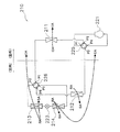
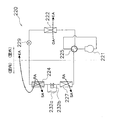
図14に示すような室外の熱源側熱交換器211と室内の利用側熱交換器212,213,214とから成る空気調和機210においても、本発明を適用することが可能であり、上記実施形態と同様の効果を得ることができる。
In such an
(4)
The present invention can also be applied to an
図14に示す空気調和機210では、利用側熱交換器として、吸着剤を有さず顕熱処理を主として行う顕熱熱交換器212と、吸着剤が表面に設けられた吸着熱交換器213,214を備えており、熱源側熱交換器として室外熱交換器211を備えている。圧縮機221は、その吐出側が第1の四路切換弁225の第1のポートP1に、その吸入側が第1の四路切換弁225の第4のポートP4にそれぞれ接続されている。室外熱交換器211は、その一端が第1の四路切換弁225の第2のポートP2に、他端が第2の四路切換弁226の第1のポートP1にそれぞれ接続されている。顕熱熱交換器212は、その一端が第1の四路切換弁225の第3のポートP3に、他端が第2の四路切換弁226の第4のポートP4にそれぞれ接続されている。また、第2の四路切換弁226の第2のポートP2から第3のポートP3へ向かって順に、第1吸着熱交換器213と膨張弁223と第2吸着熱交換器214とが配置されている。
In the
第1の四路切換弁225は、第1のポートP1と第2のポートP2が互いに連通して第3のポートP3と第4のポートP4が互いに連通する第1状態(図14に示す状態)と、第1のポートP1と第3のポートP3が互いに連通して第2のポートP2と第4のポートP4が互いに連通する第2状態とに切り換わる。一方、第2の四路切換弁226は、第1のポートP1と第2のポートP2が互いに連通して第3のポートP3と第4のポートP4が互いに連通する第1状態(図14に示す状態)と、第1のポートP1と第3のポートP3が互いに連通して第2のポートP2と第4のポートP4が互いに連通する第2状態とに切り換わる。
The first four-
図14に示す空気調和機210では、冷房除湿運転と暖房加湿運転とが行われるが、ここでは冷房除湿運転を例にとって説明を行う。
冷房除湿運転中には、第1の四路切換弁225が図14に示す第1状態に設定されるとともに膨張弁223の開度が適宜調節され、室外熱交換器211が凝縮器となって顕熱熱交換器212が蒸発器となる。一方、第1吸着熱交換器213および第2吸着熱交換器214については、第1吸着熱交換器213が凝縮器となって第2吸着熱交換器214が蒸発器となる第1状態と、第2吸着熱交換器214が凝縮器となって第1吸着熱交換器213が蒸発器となる第2状態とが、交互に繰り返される。
In the
During the cooling and dehumidifying operation, the first four-
さらに、冷房除湿運転中には、室外熱交換器211へ外気OAが供給され、顕熱熱交換器212と第1及び第2吸着熱交換器213、214へは室内からの還気RAが供給される。そして、顕熱熱交換器212を通過した還気RAが給気SAとして室内へ連続的に供給されるとともに、第1吸着熱交換器213を通過した還気RAと第2吸着熱交換器214を通過した還気RAとが、交互に給気SAとして室内へ供給される。
Further, during the cooling and dehumidifying operation, the outside air OA is supplied to the
第1状態では、第1吸着熱交換器213の吸着剤についての再生動作と、第2吸着熱交換器214の吸着剤についての吸着動作とが並行して行われる。第1状態では、第2の四路切換弁226が、図14に示す状態に設定される。この状態で、圧縮機221から吐出された冷媒は、室外熱交換器211と第1吸着熱交換器213を順に通過する間に凝縮し、膨張弁223で減圧され、その後、第2吸着熱交換器214と顕熱熱交換器212を順に通過する間に蒸発し、圧縮機221へ吸入されて圧縮される。
In the first state, the regeneration operation for the adsorbent of the first
この第1状態において、室外熱交換器211で冷媒から吸熱した外気OAが排気EAとして室外へ排出され、顕熱熱交換器212で冷却された室内からの還気RAが給気SAとして室内へ送り返される。第1吸着熱交換器213では、冷媒で加熱された吸着剤から水分が脱離し、この脱離した水分が還気RAに付与される。第1吸着熱交換器213から脱離した水分は、還気RAとともに排気EAとして室外へ排出される(図14の点線で示す還気RAの流れを参照)。第2吸着熱交換器214では、室内からの還気RA中の水分が吸着剤に吸着されて還気RAが除湿され、その際に生じた吸着熱が冷媒に吸熱される。第2吸着熱交換器214で除湿された還気RAは、給気SAとして室内へ送り返される(図14の点線で示す還気RAの流れを参照)。
In this first state, the outdoor air OA that has absorbed heat from the refrigerant in the
一方、第2状態では、第1吸着熱交換器213の吸着剤についての吸着動作と、第2吸着熱交換器214の吸着剤についての再生動作とが並行して行われる。第2状態では、圧縮機221から吐出された冷媒は、室外熱交換器211と第2吸着熱交換器214を順に通過する間に凝縮し、膨張弁223で減圧され、その後、第1吸着熱交換器213と顕熱熱交換器212を順に通過する間に蒸発し、圧縮機221へ吸入されて圧縮される。
On the other hand, in the second state, the adsorption operation for the adsorbent of the first
この第2状態では、第1状態のときと同様に、室外熱交換器211で冷媒から吸熱した外気OAが排気EAとして室外へ排出され、顕熱熱交換器212で冷却された室内からの還気RAが給気SAとして室内へ送り返される。一方、第1吸着熱交換器213では、室内からの還気RA中の水分が吸着剤に吸着されて還気RAが除湿され、その際に生じた吸着熱が冷媒に吸熱される。第1吸着熱交換器213で除湿された室内からの還気RAは、給気SAとして室内へ送り返される(図14の2点鎖線で示す還気RAの流れを参照)。第2吸着熱交換器214では、冷媒で加熱された吸着剤から水分が脱離し、この脱離した水分が還気RAに付与される。第2吸着熱交換器214から脱離した水分は、還気RAとともに排気EAとして室外へ排出される(図14の2点鎖線で示す還気RAの流れを参照)。
In this second state, as in the first state, the outside air OA that has absorbed heat from the refrigerant in the
このような図14に示す空気調和機210においても、第1状態と第2状態とを所定の時間間隔で切り換えるため、凝縮器や蒸発器として機能する第1吸着熱交換器213および第2吸着熱交換器214の凝縮器温度や蒸発器温度などに基づいて能力制御を行えば、給気SAの温度などに基づいて能力制御を行うよりも適切な制御が為されることになる。
(5)
図15に示すような室外の熱源側熱交換器222と室内の利用側熱交換器224,227とから成る空気調和機220においても、本発明を適用することが可能であり、上記実施形態と同様の効果を得ることができる。
In the
(5)
The present invention can also be applied to an
図15に示す空気調和機220では、室外に熱源側熱交換器として室外熱交換器222を備え、室内に、利用側熱交換器として、吸着剤を担持した吸着熱交換器224と、吸着剤を有さず顕熱処理を主として行う顕熱熱交換器227とを備えている。
空気調和機220では、冷房除湿運転と暖房加湿運転とが行われるが、ここでは冷房除湿運転を例にとって説明を行う。
An
In the
冷房除湿運転中には、室外熱交換器222が凝縮器となり顕熱熱交換器227が蒸発器となるように、四路切換弁225が図15に示す状態に設定される。そして、吸着熱交換器224が蒸発器となる吸着動作と、吸着熱交換器224が凝縮器となる再生動作とが、電磁弁232bおよび膨張弁229の制御によって、交互に繰り返される。さらに、冷房除湿運転中には、室外熱交換器222へ外気OAが供給され、顕熱熱交換器227および吸着熱交換器224へ室内からの還気RAが供給される。そして、顕熱熱交換器227で冷却された還気RAが室内へ連続的に供給される一方、吸着熱交換器224で除湿された還気RAは室内へ給気SAとして間欠的に供給される。
During the cooling and dehumidifying operation, the four-
吸着動作中は、電磁弁232bが開放され、膨張弁229の開度が適宜調節される。この状態で、圧縮機221から吐出された冷媒は、室外熱交換器222で凝縮した後に膨張弁229で減圧され、その後、吸着熱交換器224と顕熱熱交換器227を順に通過する間に蒸発し、圧縮機221へ吸入されて圧縮される。
この吸着動作中において、室外熱交換器222で冷媒から吸熱した外気OAが室外へ排気EAとして排出され、顕熱熱交換器227で冷却された室内からの還気RAが室内へ給気SAとして送り返される。また、吸着熱交換器224では、室内からの還気RA中の水分が吸着剤に吸着されて還気RAが除湿され、その際に生じた吸着熱が冷媒に吸熱される。吸着熱交換器224で除湿された室内からの還気RAは、給気SAとして室内へ送り返される。
During the adsorption operation, the
During this adsorption operation, the outdoor air OA that has absorbed heat from the refrigerant in the
再生動作中は、電磁弁232bが閉鎖され、膨張弁229が全開となる。この状態で、圧縮機221から吐出された冷媒は、室外熱交換器222と吸着熱交換器224を順に通過する間に凝縮し、その後、キャピラリーチューブ232aで減圧されてから顕熱熱交換器227で蒸発し、圧縮機221へ吸入されて圧縮される。
この再生動作中において、室外熱交換器222で冷媒から吸熱した外気OAが室外へ排気EAとして排出され、顕熱熱交換器227で冷却された室内からの還気RAが室内へ給気SAとして送り返される。また、吸着熱交換器224では、冷媒によって吸着剤が加熱されて再生され、吸着剤から脱離した水分が室内からの還気RAに付与される。吸着熱交換器224から脱離した水分は、室内からの還気RAとともに室外へ排気EAとして排出される(図15の2点鎖線で示す還気RAの流れを参照)。
During the regeneration operation, the
During this regeneration operation, the outside air OA that has absorbed heat from the refrigerant in the
このような図15に示す空気調和機220においても、吸着熱交換器224の吸着動作と再生動作とを所定の時間間隔で切り換えるため、凝縮器や蒸発器として機能する吸着熱交換器224の凝縮器温度や蒸発器温度などに基づいて能力制御を行えば、給気SAの温度などに基づいて能力制御を行うよりも適切な制御が為されることになる。
(6)
上記実施形態では、ユーザやメンテナンスパーソンに入力を行わせるディップスイッチ等の入力部2aを設け、その入力部2aに入力された負荷(潜熱負荷、顕熱負荷、あるいは全熱負荷)が優先して処理されるように、制御部2がインバータ圧縮機7の容量制御およびバッチ切換時間間隔の制御を行っている。この場合には、ユーザとしては、選んだ(入力した)負荷が優先して処理されるようになり、より好みにあった空調環境を得ることができるようになる。
Also in such an
(6)
In the above-described embodiment, the
このように、優先して処理すべき負荷を入力させるのではなく、優先して処理すべき負荷を自動的に制御部2が決定するようにすることもできる。
例えば、制御部2は、第1差分、第2差分、および第3差分に基づいて、優先して処理を行う負荷を決定することができる。第1差分は、全熱負荷を処理する現在の空気調和機10の能力と、室内の全熱負荷の大きさとの差である。第2差分は、潜熱負荷を処理する現在の能力と、室内の潜熱負荷の大きさとの差である。第3差分は、顕熱負荷を処理する現在の能力と、室内の顕熱負荷の大きさとの差である。具体的には、制御部2は、第1差分、第2差分、および第3差分のうち最も値が大きなものを選び、それが第1差分の場合には全熱負荷を優先して処理すべき負荷として決定し、それが第2差分の場合には潜熱負荷を優先して処理すべき負荷として決定し、それが第3差分の場合には顕熱負荷を優先して処理すべき負荷として決定する。なお、各負荷の大きさや各負荷を処理する現在の能力については、各種空気温度や冷媒状態情報(温度や圧力)などの入手データから制御部2が判断することができる。
In this way, instead of inputting the load to be processed with priority, the
For example, the
このように優先して処理すべき負荷を制御部2において自動的に決定するようにすれば、全熱負荷、潜熱負荷、顕熱負荷の処理をバランス良く行うことができるようになる。
(7)
上記実施形態では、優先して処理すべき負荷が潜熱負荷である場合に、制御部2は、バッチ切換時間間隔の変更制御による潜熱負荷の処理量の変更を、インバータ圧縮機7の容量制御による潜熱負荷の処理量の変更よりも優先させている。
If the
(7)
In the above embodiment, when the load to be preferentially processed is the latent heat load, the
このような能力制御に代えて、優先して処理すべき負荷が潜熱負荷である場合に、インバータ圧縮機7の容量制御による潜熱負荷の処理量の変更を、バッチ切換時間間隔の変更制御による潜熱負荷の処理量の変更よりも優先させることも考えられる。ここでは、潜熱負荷を優先して処理する場合に、まずインバータ圧縮機7の容量制御を行って潜熱負荷の処理量を変化させ、それでも足りないときに、バッチ切換時間間隔の変更制御を行って潜熱負荷の処理量をさらに変化させる。このように能力制御を行えば、まずインバータ圧縮機7の容量制御を行うため、潜熱負荷の処理量の変化が比較的早く現れることになり、必要な潜熱負荷の処理が早く達成されるようになる。
Instead of such capability control, when the load to be preferentially processed is a latent heat load, the change of the latent heat load processing amount by capacity control of the
(8)
上記実施形態では、優先して処理すべき負荷が顕熱負荷である場合に、制御部2は、バッチ切換時間間隔の変更制御による顕熱負荷の処理量の変更を、インバータ圧縮機7の容量制御による顕熱負荷の処理量の変更よりも優先させている。
このような能力制御に代えて、優先して処理すべき負荷が顕熱負荷である場合に、インバータ圧縮機7の容量制御による顕熱負荷の処理量の変更を、バッチ切換時間間隔の変更制御による顕熱負荷の処理量の変更よりも優先させることも考えられる。ここでは、顕熱負荷を優先して処理する場合に、まずインバータ圧縮機7の容量制御を行って顕熱負荷の処理量を変化させ、それでも足りないときに、バッチ切換時間間隔の変更制御を行って顕熱負荷の処理量をさらに変化させる。このように能力制御を行えば、まずインバータ圧縮機7の容量制御を行うため、顕熱負荷の処理量の変化が比較的早く現れることになり、必要な顕熱負荷の処理が早く達成されるようになる。
(8)
In the above embodiment, when the load to be preferentially processed is the sensible heat load, the
In place of such capability control, when the load to be preferentially processed is the sensible heat load, the change of the processing amount of the sensible heat load by the capacity control of the
(9)
上記実施形態では、優先して処理すべき負荷が全熱負荷である場合に、まずバッチ切換時間間隔の制御により潜熱負荷の処理量と顕熱負荷の処理量との比である顕潜熱処理量比を固定し、その後にインバータ圧縮機7の容量制御を行っている。
このような能力制御に代えて、優先して処理すべき負荷が全熱負荷である場合に、まずインバータ圧縮機7の容量制御を行わせることも考えられる。
(9)
In the above embodiment, when the load to be preferentially processed is the total heat load, first, the sensible latent heat treatment amount that is the ratio of the latent heat load treatment amount and the sensible heat load treatment amount by controlling the batch switching time interval The ratio is fixed, and then the capacity control of the
Instead of such capability control, it is also conceivable to first control the capacity of the
全熱負荷を増減させるときにはインバータ圧縮機7の容量を変えることが効果的であることから、ここでは、全熱負荷を優先して処理しなければならないときに、バッチ切換時間間隔の制御を行う前に、まずはインバータ圧縮機7の容量制御を行わせている。これにより、いち早く全熱負荷の処理量が増減し、全熱負荷の変化に素早く対応することができるようになる。
Since it is effective to change the capacity of the
(B) 本発明の他の実施形態(3)に係る空気調和機における加湿運転の第2状態を示す図。
1 冷媒回路
2 制御部
3 第1吸着熱交換器
5 第2吸着熱交換器
7 インバータ圧縮機
10 空気調和機
101 圧縮機
110 空気調和機
210 空気調和機
211 室外熱交換器
213 吸着熱交換器
214 吸着熱交換器
220 空気調和機
221 圧縮機
222 室外熱交換器
224 吸着熱交換器
DESCRIPTION OF
Claims (7)
熱交換器(3、5、105、213、214、224)と、
蒸発器として働く前記熱交換器によって吸熱される通過空気の水分を吸着する吸着動作、および、凝縮器として働く前記熱交換器によって加熱される通過空気に対して水分を脱離する再生動作、を行う吸着剤と、
前記吸着剤の前記吸着動作と前記再生動作とが所定の切換時間間隔で切り換わるように制御する制御部(2)と、
を備え、
前記制御部(2)は、前記蒸発器の温度、前記蒸発器の圧力、前記凝縮器の温度、および前記凝縮器の圧力のうち少なくともいずれか1つに基づいて、前記圧縮機(7、101、221)の容量制御および/または前記切換時間間隔の変更制御を行う、
空気調和機(10、110、220)。 An air conditioner (10, 110, 220) for processing an indoor latent heat load and a sensible heat load using a vapor compression refrigeration cycle having a compressor (7, 101, 221),
Heat exchangers (3, 5, 105, 213, 214, 224);
An adsorption operation for adsorbing moisture in the passing air absorbed by the heat exchanger acting as an evaporator, and a regeneration operation for desorbing moisture from the passing air heated by the heat exchanger acting as a condenser. Adsorbent to perform,
A control unit (2) for controlling the adsorption operation and the regeneration operation of the adsorbent to be switched at a predetermined switching time interval;
With
The controller (2) is configured to control the compressor (7, 101) based on at least one of the evaporator temperature, the evaporator pressure, the condenser temperature, and the condenser pressure. 221) and / or change control of the switching time interval,
Air conditioner (10, 110, 220).
請求項1に記載の空気調和機(10、220)。 The heat exchanger (3, 5, 213, 214, 224) is an adsorption heat exchanger carrying the adsorbent on its surface.
The air conditioner (10, 220) according to claim 1.
熱源側熱交換器(211、222)をさらに備えた、
請求項1または2に記載の空気調和機(220)。 The heat exchanger (213, 214, 224) is provided as a use side heat exchanger,
Further provided with a heat source side heat exchanger (211 and 222),
The air conditioner (220) according to claim 1 or 2.
請求項1から3のいずれかに記載の空気調和機(10、110、220)。 The control unit (2) further performs capacity control of the compressor and / or change control of the switching time interval based on a humidity value of indoor air.
The air conditioner (10, 110, 220) according to any one of claims 1 to 3.
請求項1から4のいずれかに記載の空気調和機。(10、110、220) The control unit (2) further performs capacity control of the compressor and / or change control of the switching time interval based on a humidity value of air flowing indoors from the heat exchanger.
The air conditioner according to any one of claims 1 to 4. (10, 110, 220)
請求項1から5のいずれかに記載の空気調和機(10、110、220)。 The controller (2) further performs capacity control of the compressor and / or change control of the switching time interval based on a temperature value of air flowing indoors from the heat exchanger.
The air conditioner (10, 110, 220) according to any one of claims 1 to 5.
前記吸着剤の前記吸着動作と前記再生動作とを所定の切換時間間隔で切り換えるように制御するとともに、
前記蒸発器の温度、前記蒸発器の圧力、前記凝縮器の温度、および前記凝縮器の圧力のうち少なくともいずれか1つに基づいて、前記圧縮機の容量制御および/または前記切換時間間隔の変更制御を行う、
ことを特徴とする空気調和機(10、110、220)の制御方法。 Using a vapor compression refrigeration cycle having a compressor (7, 101, 221) and a heat exchanger (3, 5, 105, 213, 214, 224), heat is absorbed by the heat exchanger acting as an evaporator. Using an adsorbent that can perform an adsorption operation that adsorbs moisture from the passing air and a regeneration operation that desorbs moisture from the passing air heated by the heat exchanger that acts as a condenser, A control method for an air conditioner (10, 110, 220) for processing a load and a sensible heat load,
While controlling the adsorption operation and the regeneration operation of the adsorbent at a predetermined switching time interval,
Based on at least one of the evaporator temperature, the evaporator pressure, the condenser temperature, and the condenser pressure, the compressor capacity control and / or the switching time interval change. Do control,
The control method of the air conditioner (10, 110, 220) characterized by the above-mentioned.
Priority Applications (7)
| Application Number | Priority Date | Filing Date | Title |
|---|---|---|---|
| JP2004104762A JP2005291569A (en) | 2004-03-31 | 2004-03-31 | Air conditioner and control method thereof |
| EP05727006A EP1752716A4 (en) | 2004-03-31 | 2005-03-25 | AIR CONDITIONER AND ITS CONTROL METHOD |
| CN 200580007743 CN100507389C (en) | 2004-03-31 | 2005-03-25 | Air conditioner and its control method |
| US10/593,441 US7810339B2 (en) | 2004-03-31 | 2005-03-25 | Air conditioner and method of controlling air conditioner |
| KR1020067015287A KR100781501B1 (en) | 2004-03-31 | 2005-03-25 | Air conditioner and method of controlling air conditioner |
| PCT/JP2005/005511 WO2005098326A1 (en) | 2004-03-31 | 2005-03-25 | Air conditioner and method of controlling air conditioner |
| AU2005230518A AU2005230518B2 (en) | 2004-03-31 | 2005-03-25 | Air conditioner and method of controlling air conditioner |
Applications Claiming Priority (1)
| Application Number | Priority Date | Filing Date | Title |
|---|---|---|---|
| JP2004104762A JP2005291569A (en) | 2004-03-31 | 2004-03-31 | Air conditioner and control method thereof |
Publications (1)
| Publication Number | Publication Date |
|---|---|
| JP2005291569A true JP2005291569A (en) | 2005-10-20 |
Family
ID=35324696
Family Applications (1)
| Application Number | Title | Priority Date | Filing Date |
|---|---|---|---|
| JP2004104762A Pending JP2005291569A (en) | 2004-03-31 | 2004-03-31 | Air conditioner and control method thereof |
Country Status (2)
| Country | Link |
|---|---|
| JP (1) | JP2005291569A (en) |
| CN (1) | CN100507389C (en) |
Cited By (3)
| Publication number | Priority date | Publication date | Assignee | Title |
|---|---|---|---|---|
| KR101362144B1 (en) * | 2011-02-10 | 2014-02-21 | 한라비스테온공조 주식회사 | Air conditioning system for electric vehicle |
| CN110595000A (en) * | 2019-09-18 | 2019-12-20 | 宁波奥克斯电气股份有限公司 | Air pipe indoor unit static pressure self-adaptive control method and system and air pipe indoor unit |
| JPWO2022162901A1 (en) * | 2021-01-29 | 2022-08-04 |
Families Citing this family (15)
| Publication number | Priority date | Publication date | Assignee | Title |
|---|---|---|---|---|
| JP5018402B2 (en) * | 2007-10-31 | 2012-09-05 | ダイキン工業株式会社 | Humidity control device |
| CN102466380A (en) * | 2010-11-15 | 2012-05-23 | 中兴电工机械股份有限公司 | Control method of adsorption air conditioning equipment |
| CN102506475A (en) * | 2011-10-19 | 2012-06-20 | 上海交通大学 | Heat pump system of heat humidity independent control driven by condensation waste heat and based on solid dehumidification |
| CN103438632B (en) * | 2013-08-02 | 2015-08-19 | 南通大学 | High efficiency adsorption type heat pump |
| CN104019528B (en) * | 2014-06-26 | 2016-06-22 | 东元总合科技(杭州)有限公司 | The energy-efficient operating control algolithm of convertible frequency air-conditioner |
| JP6257788B2 (en) * | 2014-09-26 | 2018-01-10 | 三菱電機株式会社 | Dehumidifier |
| CN104236020B (en) * | 2014-09-30 | 2017-01-11 | 张迎春 | Method and device for controlling air conditioning system |
| KR101667979B1 (en) * | 2015-06-19 | 2016-10-21 | 한국생산기술연구원 | Air conditioner with dehumidification and humidification function and method of dehumidified cooling and humidified heating using the same |
| CN105258276A (en) * | 2015-09-24 | 2016-01-20 | 珠海格力电器股份有限公司 | Air conditioning system and control method thereof |
| CN106671728A (en) * | 2015-11-06 | 2017-05-17 | 福特环球技术公司 | Air conditioning system and control method thereof |
| US11041649B2 (en) * | 2016-11-16 | 2021-06-22 | Mitsubishi Electric Corporation | Air-conditioning control device and air-conditioning control method |
| CN109654660B (en) * | 2018-12-24 | 2021-06-18 | 美的集团武汉制冷设备有限公司 | Air conditioner and control method and device thereof |
| CN110578998A (en) * | 2019-08-06 | 2019-12-17 | 武汉理工大学 | A method for controlling the evaporation pressure of an air-conditioning evaporator |
| CN111578373B (en) * | 2020-05-08 | 2022-09-06 | 青岛海尔空调器有限总公司 | Energy-saving air conditioning system with independent temperature and humidity control function |
| CN111578481B (en) * | 2020-05-12 | 2022-09-06 | 青岛海尔空调器有限总公司 | Dehumidification control method of temperature and humidity independent control air conditioning system |
Family Cites Families (5)
| Publication number | Priority date | Publication date | Assignee | Title |
|---|---|---|---|---|
| JPS62129639A (en) * | 1985-11-29 | 1987-06-11 | Toshiba Corp | Air conditioner |
| CN1035899C (en) * | 1994-03-04 | 1997-09-17 | 李元哲 | Adsorption-type moisture-removing air conditioner with swinging valve |
| JPH08178399A (en) | 1994-12-28 | 1996-07-12 | Matsushita Electric Ind Co Ltd | Dehumidifying / humidifying device |
| JP4300631B2 (en) * | 1999-04-30 | 2009-07-22 | ダイキン工業株式会社 | Air conditioner |
| JP2003161465A (en) * | 2001-11-26 | 2003-06-06 | Daikin Ind Ltd | Humidity control device |
-
2004
- 2004-03-31 JP JP2004104762A patent/JP2005291569A/en active Pending
-
2005
- 2005-03-25 CN CN 200580007743 patent/CN100507389C/en not_active Expired - Fee Related
Cited By (5)
| Publication number | Priority date | Publication date | Assignee | Title |
|---|---|---|---|---|
| KR101362144B1 (en) * | 2011-02-10 | 2014-02-21 | 한라비스테온공조 주식회사 | Air conditioning system for electric vehicle |
| CN110595000A (en) * | 2019-09-18 | 2019-12-20 | 宁波奥克斯电气股份有限公司 | Air pipe indoor unit static pressure self-adaptive control method and system and air pipe indoor unit |
| JPWO2022162901A1 (en) * | 2021-01-29 | 2022-08-04 | ||
| WO2022162901A1 (en) * | 2021-01-29 | 2022-08-04 | 三菱電機株式会社 | Outside-air processing device |
| JP7395030B2 (en) | 2021-01-29 | 2023-12-08 | 三菱電機株式会社 | Outside air processing equipment |
Also Published As
| Publication number | Publication date |
|---|---|
| CN1946974A (en) | 2007-04-11 |
| CN100507389C (en) | 2009-07-01 |
Similar Documents
| Publication | Publication Date | Title |
|---|---|---|
| KR100781501B1 (en) | Air conditioner and method of controlling air conditioner | |
| JP3624910B2 (en) | Humidity control device | |
| US7841194B2 (en) | Air conditioner and method of controlling such | |
| JP2005291569A (en) | Air conditioner and control method thereof | |
| KR100959226B1 (en) | Air conditioning system | |
| JP5218135B2 (en) | Humidity control device | |
| JP2010281476A (en) | Humidity control device | |
| JP3992051B2 (en) | Air conditioning system | |
| WO2005095865A1 (en) | Air conditioner and method of controlling the same | |
| WO2005103577A1 (en) | Humidity controller | |
| JP3712001B2 (en) | Air conditioner and control method of air conditioner | |
| JP2007010231A (en) | Humidity control device | |
| JP2005140372A (en) | Air conditioner | |
| JP4561476B2 (en) | Air conditioning system | |
| JP4179051B2 (en) | Humidity control device | |
| JP4179052B2 (en) | Humidity control device | |
| JP2005164220A (en) | Air conditioner | |
| JP4457653B2 (en) | Humidity control device | |
| JP4273829B2 (en) | Humidity control device | |
| JP4529530B2 (en) | Humidity control device |
Legal Events
| Date | Code | Title | Description |
|---|---|---|---|
| A131 | Notification of reasons for refusal |
Free format text: JAPANESE INTERMEDIATE CODE: A131 Effective date: 20050726 |
|
| A02 | Decision of refusal |
Free format text: JAPANESE INTERMEDIATE CODE: A02 Effective date: 20051129 |