WO2022158584A1 - トーチ及びその走査方法 - Google Patents
トーチ及びその走査方法 Download PDFInfo
- Publication number
- WO2022158584A1 WO2022158584A1 PCT/JP2022/002312 JP2022002312W WO2022158584A1 WO 2022158584 A1 WO2022158584 A1 WO 2022158584A1 JP 2022002312 W JP2022002312 W JP 2022002312W WO 2022158584 A1 WO2022158584 A1 WO 2022158584A1
- Authority
- WO
- WIPO (PCT)
- Prior art keywords
- torch
- consumable electrode
- electrode
- tip
- scanning
- Prior art date
- Legal status (The legal status is an assumption and is not a legal conclusion. Google has not performed a legal analysis and makes no representation as to the accuracy of the status listed.)
- Ceased
Links
Images





Classifications
-
- B—PERFORMING OPERATIONS; TRANSPORTING
- B23—MACHINE TOOLS; METAL-WORKING NOT OTHERWISE PROVIDED FOR
- B23K—SOLDERING OR UNSOLDERING; WELDING; CLADDING OR PLATING BY SOLDERING OR WELDING; CUTTING BY APPLYING HEAT LOCALLY, e.g. FLAME CUTTING; WORKING BY LASER BEAM
- B23K9/00—Arc welding or cutting
- B23K9/02—Seam welding; Backing means; Inserts
- B23K9/022—Welding by making use of electrode vibrations
-
- B—PERFORMING OPERATIONS; TRANSPORTING
- B23—MACHINE TOOLS; METAL-WORKING NOT OTHERWISE PROVIDED FOR
- B23K—SOLDERING OR UNSOLDERING; WELDING; CLADDING OR PLATING BY SOLDERING OR WELDING; CUTTING BY APPLYING HEAT LOCALLY, e.g. FLAME CUTTING; WORKING BY LASER BEAM
- B23K9/00—Arc welding or cutting
- B23K9/16—Arc welding or cutting making use of shielding gas
- B23K9/167—Arc welding or cutting making use of shielding gas and of a non-consumable electrode
-
- B—PERFORMING OPERATIONS; TRANSPORTING
- B23—MACHINE TOOLS; METAL-WORKING NOT OTHERWISE PROVIDED FOR
- B23K—SOLDERING OR UNSOLDERING; WELDING; CLADDING OR PLATING BY SOLDERING OR WELDING; CUTTING BY APPLYING HEAT LOCALLY, e.g. FLAME CUTTING; WORKING BY LASER BEAM
- B23K9/00—Arc welding or cutting
- B23K9/24—Features related to electrodes
- B23K9/28—Supporting devices for electrodes
-
- B—PERFORMING OPERATIONS; TRANSPORTING
- B23—MACHINE TOOLS; METAL-WORKING NOT OTHERWISE PROVIDED FOR
- B23K—SOLDERING OR UNSOLDERING; WELDING; CLADDING OR PLATING BY SOLDERING OR WELDING; CUTTING BY APPLYING HEAT LOCALLY, e.g. FLAME CUTTING; WORKING BY LASER BEAM
- B23K9/00—Arc welding or cutting
- B23K9/24—Features related to electrodes
- B23K9/28—Supporting devices for electrodes
- B23K9/29—Supporting devices adapted for making use of shielding means
Definitions
- the present invention relates to a torch and its scanning method.
- GTAW Gas Tungsten Arc welding
- TIG welding Tungsten Inert Gas welding
- plasma arc welding Non-consumable electrode gas shielded arc welding
- GMAW Gas Metal Arc welding
- MIG welding Metal Inert Gas welding
- MAG welding Metal Active Gas welding
- carbon dioxide gas arc welding is used.
- These welding methods generally use a welding torch to generate an arc between the electrode and the work piece (base metal), and the heat of this arc melts the work piece to form a molten pool. Welding is performed while During welding, a shielding gas is emitted from a torch nozzle surrounding the electrode, and the atmosphere (air) is blocked by this shielding gas.
- TIG welding it is common to insert a filler wire laterally into the non-consumable electrode located in the center of the torch toward the tip of the non-consumable electrode. Also, the filler wire is inserted from the front or rear of the torch in the scanning direction. Therefore, when scanning the welding torch in the plane, it is necessary to change the inserting direction of the filler wire according to the scanning direction of the welding torch.
- Patent Document 1 discloses an electrode rotatably supported by a torch body, an ultrasonic motor for rotating or oscillating the electrode, and a welding wire disposed at the axial center of the torch body for supplying welding wire.
- a welding torch with an insulating tube is described.
- the welding torch disclosed in Patent Document 1 mentioned above uses a special electrode in which the tip of the electrode that rotates around the filler wire is bent toward the tip of the filler wire. In this case, it is impossible to use a general-purpose tungsten electrode rod. Moreover, when the tip of the electrode wears out, it is necessary to replace such a special electrode as a whole. Furthermore, the electrode has a structure that is directly attached to the ultrasonic motor that rotates the electrode, and the method of power supply to the electrode is also unclear.
- the present invention has been proposed in view of such conventional circumstances. It is an object of the present invention to provide a torch scanning method suitable for scanning a
- the present invention provides the following means.
- a wire guide that feeds a filler wire toward its tip; a rotating cylinder attached rotatably around the axis of the wire guide while surrounding the wire guide; a torch body that holds the rotating barrel inside while the rotating barrel protrudes from the tip side; a torch nozzle that is attached to the tip side of the rotating cylinder in a state surrounding the periphery of the tip side of the wire guide and that emits a shielding gas from the tip;
- the torch nozzle is provided with a non-consumable electrode extending toward the tip of the filler wire, A torch, wherein a direction of the non-consumable electrode facing the filler wire can be changed by rotating the rotary cylinder.
- the electrode mounting portion includes an electrode mounting member detachably attached to the torch nozzle, The torch according to [2] above, wherein the non-consumable electrode is detachably attached to the electrode attachment member.
- the present invention provides a torch suitable for rotatably disposing a non-consumable electrode about a centrally located filler wire, as well as a torch suitable for scanning such a torch. It is possible to provide a scanning method.
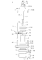
- FIG. 1 is a side view showing the configuration of a torch according to one embodiment of the present invention
- FIG. FIG. 2 is a cross-sectional view showing the configuration of the torch shown in FIG. 1
- FIG. 2 is an exploded side view showing the configuration of the torch shown in FIG. 1
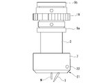
- FIG. 4 is a side view showing a state in which a non-consumable electrode is attached to the torch nozzle through an electrode attachment portion
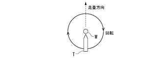
- FIG. 4 is a schematic diagram for explaining a torch scanning method according to the first embodiment of the present invention
- FIG. 7 is a schematic diagram for explaining a torch scanning method according to a second embodiment of the present invention
- FIG. 10 is a schematic diagram for explaining a torch scanning method according to a third embodiment of the present invention
- FIG. 4 is a schematic diagram showing the positional relationship of a non-consumable electrode with respect to a filler wire;
- FIG. 1 is a side view showing the configuration of the torch 1.
- FIG. FIG. 2 is a cross-sectional view showing the configuration of the torch 1.
- FIG. 3 is an exploded side view showing the configuration of the torch 1.
- FIG. 4 is a side view showing a state in which the non-consumable electrode T is attached via the electrode attachment portion 21 to the torch nozzle 7 attached to the tip side of the rotary cylinder 3.
- FIG. 1 is a side view showing the configuration of the torch 1.
- FIG. FIG. 2 is a cross-sectional view showing the configuration of the torch 1.
- FIG. 3 is an exploded side view showing the configuration of the torch 1.
- FIG. FIG. 4 is a side view showing a state in which the non-consumable electrode T is attached via the electrode attachment portion 21 to the torch nozzle 7 attached to the tip side of the rotary cylinder 3.
- the torch 1 of this embodiment has a non-consumable electrode T rotatably arranged around a filler wire W located in the center.
- this torch 1 includes a wire guide 2 , a rotary cylinder 3 , a torch body 4 , a rotary drive mechanism 5 , a cooling block 6 and a torch nozzle 7 .
- the wire guide 2 feeds the filler wire W toward the distal end, and consists of a substantially cylindrical long member having a central hole (not shown) penetrating in the axial direction.
- Examples of the material of the wire guide 2 include metals such as brass, copper, copper alloys, carbon steel, stainless steel, and titanium, and ceramics.
- the wire guide 2 is held inside the torch body 4 while passing through the center of the torch body 4 .
- the proximal end of the wire guide 2 is connected to a wire feeder (not shown) that feeds the filler wire W automatically. Thereby, the wire guide 2 feeds the filler wire W to the tip side through the center hole.
- the filler wire W is not particularly limited, and it is possible to appropriately select and use the filler wire W that matches the application.
- a plurality of ejection holes 2a for ejecting the shielding gas G are provided side by side in the circumferential direction on the tip side of the wire guide 2 .
- a connecting portion 2b to which a hose (not shown) for introducing the shielding gas G is connected is provided on the base end side of the wire guide 2. As shown in FIG.
- the shielding gas G is not particularly limited.
- a mixed gas to which a gas such as (N 2 ) is added can be used.
- a mixed gas obtained by adding a gas such as hydrogen (H 2 ) or nitrogen (N 2 ) to a mixed gas of argon (Ar) and helium (He) can be used.
- argon (Ar) or a mixed gas of argon (Ar) and helium (He) may be used, for example, carbon dioxide (CO 2 ) or oxygen (O 2 ). You may use what added oxidizing gas, such as.
- a contact tip 8 for sending out the filler wire W from the tip is detachably attached to the tip of the wire guide 2 .
- the contact tip 8 is made of a substantially cylindrical member having a central hole 8a extending therethrough in the axial direction. The contact tip 8 can send out the filler wire W from the tip through the center hole 8a.
- the contact tip 8 is attached to the tip side of the wire guide 2 by screwing. As a result, when spatter or the like adheres to the contact tip 8 or when the center hole 8a is deformed or worn, the contact tip 8 can be removed and cleaned or replaced.
- the contact tip 8 a commercially available product (general-purpose product) can be used as well as a custom-made product (dedicated product).
- Examples of the material of the contact tip 8 include copper, copper alloys, and ceramics.
- the rotary cylinder 3 is composed of a substantially cylindrical member having a central hole 3a that penetrates in the axial direction.
- metals such as brass, copper, a copper alloy, carbon steel, stainless steel, and titanium, can be mentioned as the material of the rotary cylinder 3, for example.
- the rotary cylinder 3 is held inside the torch body 4 with the wire guide 2 arranged inside the center hole 3 a and surrounding the wire guide 2 . Further, the rotating cylinder 3 is rotatably mounted around the axis of the wire guide 2 via a plurality of (two in this embodiment) bearings 9a and 9b arranged in parallel in the axial direction.
- a gas passage (gap) R is formed through which the shielding gas G ejected from the plurality of ejection holes 2a flows.
- the shielding gas G can be discharged from the periphery of the wire guide 2 on the distal end side.
- the torch body 4 has a first ring member 10, a second ring member 11, a third ring member 12 and a sleeve member 13 made of insulating resin.
- the torch body 4 also has a first frame member 14, a second frame member 15, and a pair of struts 16 made of metal.
- the torch body 4 holds the bearing 9a inside the second ring member 11 with the first frame member 14 sandwiched between the first ring member 10 and the second ring member 11. . Further, the torch body 4 holds the bearing 9 b inside the third ring member 12 with the second frame member 15 sandwiched between the third ring member 12 and the sleeve member 13 .
- the first frame member 14 and the second frame member 15 are connected via a pair of struts 16 .
- the torch body 4 holds the wire guide 2 inside the sleeve member 13 . Therefore, the wire guide 2 and the rotating cylinder 3 are electrically insulated via the sleeve member 13 .
- the rotary drive mechanism 5 rotates the rotary cylinder 3.
- a drive gear 18 attached to a rotary shaft 17 of a drive motor (not shown) and a driven gear 19 attached to the rotary cylinder 3 are connected to each other. It has a mated configuration.
- the rotating shaft 17 is rotatably supported between the first frame member 14 and the second frame member 15 .
- the rotation of the rotary shaft 17 by the drive motor is transmitted from the drive gear 18 to the driven gear 19 , thereby rotating the rotary barrel 3 around the wire guide 2 . .
- the cooling block 6 cools the rotating barrel 3, and is attached to the tip side (first ring member 10) of the torch body 4 while surrounding the periphery of the tip side of the rotating barrel 3.
- the cooling block 6 includes a liquid flow path 6a through which the cooling water L is circulated, an inlet connection portion 6b through which the cooling water L is supplied to the liquid flow path 6a, and an outlet through which the cooling water L is discharged from the liquid flow path 6a. side connections (not shown) are provided.
- a cooling device (chiller) is connected to these connecting portions 6b, so that the cooling water L in the liquid flow path 6a is circulated.
- the material of the cooling block 6 include conductive metals such as brass, copper, copper alloys, carbon steel, stainless steel, and titanium.
- the torch nozzle 7 consists of a substantially cylindrical member.
- Examples of the material of the torch nozzle 7 include conductive metals such as copper, copper alloys, carbon steel, and stainless steel.
- the torch nozzle 7 is attached to the distal end side of the rotating cylinder 3 while surrounding the periphery of the filler wire W on the distal end side. Thereby, the torch nozzle 7 is rotatable about the axis of the wire guide 2 together with the rotary cylinder 3 . Shielding gas G ejected from the plurality of ejection holes 2 a of the wire guide 2 is emitted from the tip of the torch nozzle 7 .
- the torch nozzle 7 is thermally connected to the cooling block 6 and electrically connected to the cooling block 6 . Between the cooling block 6 and the torch nozzle 7, there is provided a power supply section 20 to which power is supplied while being in sliding contact with each other. That is, between the cooling block 6 and the torch nozzle 7, the surfaces facing each other are in sliding contact, and power is supplied through the power supply portion 20 that is in sliding contact with each other.
- the power supply unit 20 may be configured such that a groove is provided in either one of the sliding contact surfaces. Also, other than the grooves, shapes that reduce the mutual sliding contact area may be used.
- the torch nozzle 7 is provided with an electrode mounting portion 21 for detachably mounting the non-consumable electrode T.
- the electrode mounting portion 21 has an electrode mounting member 22 detachably mounted on the distal end side of the rotary cylinder 3, and has a structure in which the non-consumable electrode T is detachably mounted on the electrode mounting member 22. ing.
- the electrode mounting member 22 is arranged inside a notch portion 7a that partially cuts out the torch nozzle 7, and is detachably attached to the torch nozzle 7 by screwing.
- Examples of the material of the electrode mounting member 22 include conductive metals such as brass, copper, copper alloys, carbon steel, stainless steel, and titanium.
- the non-consumable electrode T is detachably attached to the electrode attachment member 22 by screwing.
- a commercially available product general-purpose product
- the non-consumable electrode T is an elongated electrode rod made of a metal material with a high melting point such as tungsten.
- the non-consumable electrode T can be made by adding an oxide such as thorium oxide, lanthanum oxide, cerium oxide, yttrium oxide, or zirconium oxide.
- the length of the non-consumable electrode T can be adjusted by changing the mounting position of the non-consumable electrode T with respect to the electrode mounting member 22. Further, in the electrode mounting portion 21 , the tilt of the non-consumable electrode T can be adjusted by changing the mounting angle of the electrode mounting member 22 with respect to the torch nozzle 7 .
- the inclination of the non-consumable electrode T is about 10° to 45° with respect to the filler wire W.
- the non-consumable electrode T may be directly attached to the torch nozzle 7 .
- the non-consumable electrode T extending from the electrode mounting portion 21 toward the tip of the filler wire W is changed in the direction facing the filler wire W by the rotation of the rotating barrel 3. It is assumed to be changeable.
- the non-consumable electrode T is detachably attached to the electrode attachment member 22 attached to the torch nozzle 7 in the electrode attachment portion 21 described above. Further, in the power supply unit 20 described above, power is supplied while the cooling block 6 and the torch nozzle 7 are in sliding contact with each other.
- the non-consumable electrode T can be easily attached to the torch nozzle 7, and power can be reliably supplied to the non-consumable electrode T.
- the non-consumable electrode T is changed.
- the length and inclination of the consumable electrode T can be adjusted.
- a commercially available non-consumable electrode T (general-purpose product) can be used instead of a custom-made non-consumable electrode T (dedicated product), and the non-consumable electrode T can be easily replaced. is.
- the torch 1 of the present embodiment is suitable for rotatably arranging the non-consumable electrode T around the filler wire W located in the center, not only for general TIG welding, but also for metal lamination welding, for example. It can be suitably used for modeling technology (WAAM), build-up welding, and the like. It can also be used for all joint shapes such as butt welds, lap welds and fillet welds.
- WAAM modeling technology
- build-up welding and the like.
- all joint shapes such as butt welds, lap welds and fillet welds.
- the torch 1 is scanned in the plane, and the heat of the arc generated between the base material and the non-consumable electrode T melts the filler wire W, which is the material for modeling.
- This modeling material is layered according to the desired shape.
- the non-consumable electrode T is inserted laterally toward the tip of the filler wire W located in the center. At this time, the non-consumable electrode T is inserted from the front or rear of the torch 1 in the scanning direction.
- the torch 1 of the present embodiment since the orientation of the non-consumable electrode T facing the filler wire W can be changed according to the scanning direction of the torch 1, it is possible to accurately form a three-dimensional metal additive manufacturing object. is.
- a grip or the like for holding the torch 1 may be attached to a position control robot (not shown) for the torch 1.
- FIGS. 5 to 7 are schematic diagrams for explaining the scanning method of the torch 1.
- the scanning method of the torch 1 according to the first embodiment of the present invention is characterized in that the torch 1 is scanned after changing the orientation of the non-consumable electrode T facing the filler wire W, as shown in FIG. do.
- the non-consumable electrode T is oriented so as to face the filler wire W so that the non-consumable electrode T is inserted from the front or rear of the torch 1 in the scanning direction. to change Accordingly, it is possible to reliably change the orientation of the non-consumable electrode T facing the filler wire W in accordance with the scanning direction of the torch 1 .
- the scanning method of the torch 1 according to the second embodiment of the present invention is to change the orientation of the non-consumable electrode T facing the filler wire W while scanning the torch 1, as shown in FIG. characterized by
- the non-consumable electrode T is inserted from the front or the rear in the scanning direction of the torch 1 according to the change in the scanning direction of the torch 1 during scanning of the torch 1. facing the filler wire W. Accordingly, it is possible to quickly change the orientation of the non-consumable electrode T facing the filler wire W in accordance with the scanning direction of the torch 1 .
- a method of scanning the torch 1 according to the third embodiment of the present invention is characterized by scanning the torch while rotating the non-consumable electrode T around the filler wire W, as shown in FIG.
- the rotation of the non-consumable electrode T is not limited to rotating the non-consumable electrode T in one direction, and it is also possible to alternately rotate the non-consumable electrode T in both directions (reciprocating rotation).
- the tip of the non-consumable electrode T may be displaced from the tip of the filler wire W, for example, as shown in FIG.
- the rotation drive mechanism 5 is not limited to the configuration described above, and may have a configuration using a pulley mechanism or a configuration in which the drive motor 23 directly drives the rotary cylinder 3 .
- the wire guide 2 may be electrically connected to a welding power source and used as a hot wire.
- a commercially available consumable electrode type (MIG, MAG) torch may be used as the wire guide 2 .
- MIG, MAG commercially available consumable electrode type
- the torch nozzle may be removed before use.
- the present invention is not limited to the non-consumable electrode type torch described above, and can also be applied to consumable electrode type (MIG, MAG) torches.
- MIG consumable electrode type
Landscapes
- Engineering & Computer Science (AREA)
- Physics & Mathematics (AREA)
- Plasma & Fusion (AREA)
- Mechanical Engineering (AREA)
- Arc Welding In General (AREA)
- Butt Welding And Welding Of Specific Article (AREA)
Abstract
中心に位置するフィラーワイヤの周囲で非消耗電極を回転自在に配置するのに好適なトーチを提供することを目的とし、フィラーワイヤWを先端に向けて送給するワイヤガイド(2)と、ワイヤガイド(2)の周囲を囲んだ状態で、ワイヤガイド(2)の軸回りに回転自在に取り付けられた回転筒(3)と、回転筒(3)を先端側から突出させた状態で、回転筒3を内側に保持するトーチボディ(4)と、ワイヤガイド(2)の先端側の周囲を囲んだ状態で、回転筒(3)の先端側に取り付けられると共に、シールドガス(G)を先端から放出するトーチノズル(7)とを備え、トーチノズル(7)には、フィラーワイヤWの先端に向かって延在する非消耗電極(T)が設けられ、非消耗電極(T)のフィラーワイヤ(W)と対向する向きが回転筒(3)の回転により変更自在とされているトーチを提供する。
Description
本発明は、トーチ及びその走査方法に関する。
従来より、金属や非鉄金属などを母材として用いた構造物(被溶接物)の溶接には、例えばTIG溶接(Tungsten Inert Gas welding)又はプラズマアーク溶接等のGTAW(Gas Tungsten Arc welding)と呼ばれる非消耗電極式のガスシールドアーク溶接が用いられている。また、MIG溶接(Metal Inert Gas welding)、MAG溶接(Metal Active Gas welding)又は炭酸ガスアーク溶接等のGMAW(Gas Metal Arc welding)と呼ばれる消耗電極式のガスシールドアーク溶接が用いられている。
これらの溶接方法では、一般に溶接トーチを使用し、電極と被溶接物(母材)との間でアークを発生させて、このアークの熱により被溶接物を溶かして溶融池(プール)を形成しながら溶接が行われる。また、溶接中は電極の周囲を囲むトーチノズルからシールドガスを放出し、このシールドガスで大気(空気)を遮断する。
ところで、近年では、アーク溶接を応用した金属積層造形技術(WAAM:Wire and Arc Additive Manufacturing)の開発も進められている。金属積層造形技術では、溶接トーチを面内で走査し、母材と非消耗電極との間で発生するアークの熱により造形用材料となるフィラーワイヤを溶融させながら、この造形用材料を目的の形状に合わせて積層していく。これにより、立体的な金属積層造形物を形成することが可能である。
TIG溶接では、トーチの中心に位置する非消耗電極に対してフィラーワイヤを横方向から非消耗電極の先端に向けて挿入するのが一般的である。また、フィラーワイヤは、トーチの走査方向の前方又は後方から挿入される。このため、溶接トーチを面内で走査する際は、この溶接トーチの走査方向に合わせてフィラーワイヤの挿入方向を変更する必要がある。
これに対して、トーチの中心から溶接ワイヤを送給しながら、溶接ワイヤの周囲で電極を回転又はオシレートさせるTIG溶接方法が提案されている(下記特許文献1を参照。)。また、下記特許文献1には、トーチ本体に回転自在に支持された電極と、当該電極を回転又はオシレートさせる超音波モータと、当該トーチ本体の軸心に配設されて溶接ワイヤの供給に供される絶縁管とを備えた溶接トーチが記載されている。
しかしながら、上述した特許文献1が開示する溶接トーチでは、フィラーワイヤの周囲で回転する電極の先端をフィラーワイヤの先端に向かって屈曲させた特殊な電極を用いている。この場合、汎用のタングステン電極棒を用いることは不可能である。また、電極の先端が消耗した場合、このような特殊な電極を丸ごと交換する必要がある。さらに、電極は、この電極を回転させる超音波モータに直接取り付けられた構造を有しており、この電極への給電方法も不明確である。
したがって、上述した特許文献1に記載のTIG溶接方法を金属積層造形技術に適用することは困難であり、コスト面から見ても実施は困難である。
本発明は、このような従来の事情に鑑みて提案されたものであり、中心に位置するフィラーワイヤの周囲で非消耗電極を回転自在に配置するのに好適なトーチ、並びに、そのようなトーチを走査するのに好適なトーチの走査方法を提供することを目的とする。
上記目的を達成するために、本発明は以下の手段を提供する。
〔1〕 フィラーワイヤを先端に向けて送給するワイヤガイドと、
前記ワイヤガイドの周囲を囲んだ状態で、前記ワイヤガイドの軸回りに回転自在に取り付けられた回転筒と、
前記回転筒を先端側から突出させた状態で、前記回転筒を内側に保持するトーチボディと、
前記ワイヤガイドの先端側の周囲を囲んだ状態で、前記回転筒の先端側に取り付けられると共に、シールドガスを先端から放出するトーチノズルとを備え、
前記トーチノズルには、前記フィラーワイヤの先端に向かって延在する非消耗電極が設けられ、
前記非消耗電極の前記フィラーワイヤと対向する向きが前記回転筒の回転により変更自在とされていることを特徴とするトーチ。
〔2〕 前記トーチノズルには、前記非消耗電極を着脱自在に取り付ける電極取付部が設けられていることを特徴とする前記〔1〕に記載のトーチ。
〔3〕 前記電極取付部は、前記トーチノズルに着脱自在に取り付けられた電極取付部材を含み、
前記非消耗電極は、前記電極取付部材に対して着脱自在に取り付けられていることを特徴とする前記〔2〕に記載のトーチ。
〔4〕 前記電極取付部において、前記非消耗電極の長さが調節自在とされていることを特徴とする前記〔2〕又は〔3〕に記載のトーチ。
〔5〕 前記電極取付部において、前記非消耗電極の傾きが調節自在とされていることを特徴とする前記〔2〕~〔4〕の何れか一項に記載のトーチ。
〔6〕 前記非消耗電極が前記トーチノズルに直接取り付けられていることを特徴とする前記〔1〕に記載のトーチ。
〔7〕 前記回転筒の周囲を囲んだ状態で、前記トーチボディに取り付けられると共に、冷却液が循環される流路が設けられた冷却ブロックを備えることを特徴とする前記〔1〕~〔6〕の何れか一項に記載のトーチ。
〔8〕 前記トーチノズルは、前記冷却ブロックと熱的に接続されると共に、前記冷却ブロックと電気的に接続されていることを特徴とする前記〔7〕に記載のトーチ。
〔9〕 前記冷却ブロックと前記トーチノズルとの間には、互いに摺接しながら給電される給電部が設けられていることを特徴とする前記〔8〕に記載のトーチ。
〔10〕 前記ワイヤガイドと前記回転筒との間で流通されるシールドガスを先端から放出することを特徴とする前記〔1〕~〔9〕の何れか一項に記載のトーチ。
〔11〕 前記ワイヤガイドの先端側には、前記フィラーワイヤを先端から送り出すコンタクトチップが着脱自在に取り付けられていることを特徴とする前記〔1〕~〔10〕の何れか一項に記載のトーチ。
〔12〕 前記回転筒を回転させる回転駆動機構を備えることを特徴とする前記〔1〕~〔11〕の何れか一項に記載のトーチ。
〔13〕 前記〔1〕~〔12〕の何れか一項に記載のトーチの走査方法であって、
前記非消耗電極の前記フィラーワイヤと対向する向きを変更した後に、前記トーチを走査することを特徴とするトーチの走査方法。
〔14〕 前記〔1〕~〔12〕の何れか一項に記載のトーチの走査方法であって、
前記トーチを走査している間に、前記非消耗電極の前記フィラーワイヤと対向する向きを変更することを特徴とするトーチの走査方法。
〔15〕 前記〔1〕~〔12〕の何れか一項に記載のトーチの走査方法であって、
前記フィラーワイヤの周囲で前記非消耗電極を回転させながら、前記トーチを走査することを特徴とするトーチの走査方法。
〔1〕 フィラーワイヤを先端に向けて送給するワイヤガイドと、
前記ワイヤガイドの周囲を囲んだ状態で、前記ワイヤガイドの軸回りに回転自在に取り付けられた回転筒と、
前記回転筒を先端側から突出させた状態で、前記回転筒を内側に保持するトーチボディと、
前記ワイヤガイドの先端側の周囲を囲んだ状態で、前記回転筒の先端側に取り付けられると共に、シールドガスを先端から放出するトーチノズルとを備え、
前記トーチノズルには、前記フィラーワイヤの先端に向かって延在する非消耗電極が設けられ、
前記非消耗電極の前記フィラーワイヤと対向する向きが前記回転筒の回転により変更自在とされていることを特徴とするトーチ。
〔2〕 前記トーチノズルには、前記非消耗電極を着脱自在に取り付ける電極取付部が設けられていることを特徴とする前記〔1〕に記載のトーチ。
〔3〕 前記電極取付部は、前記トーチノズルに着脱自在に取り付けられた電極取付部材を含み、
前記非消耗電極は、前記電極取付部材に対して着脱自在に取り付けられていることを特徴とする前記〔2〕に記載のトーチ。
〔4〕 前記電極取付部において、前記非消耗電極の長さが調節自在とされていることを特徴とする前記〔2〕又は〔3〕に記載のトーチ。
〔5〕 前記電極取付部において、前記非消耗電極の傾きが調節自在とされていることを特徴とする前記〔2〕~〔4〕の何れか一項に記載のトーチ。
〔6〕 前記非消耗電極が前記トーチノズルに直接取り付けられていることを特徴とする前記〔1〕に記載のトーチ。
〔7〕 前記回転筒の周囲を囲んだ状態で、前記トーチボディに取り付けられると共に、冷却液が循環される流路が設けられた冷却ブロックを備えることを特徴とする前記〔1〕~〔6〕の何れか一項に記載のトーチ。
〔8〕 前記トーチノズルは、前記冷却ブロックと熱的に接続されると共に、前記冷却ブロックと電気的に接続されていることを特徴とする前記〔7〕に記載のトーチ。
〔9〕 前記冷却ブロックと前記トーチノズルとの間には、互いに摺接しながら給電される給電部が設けられていることを特徴とする前記〔8〕に記載のトーチ。
〔10〕 前記ワイヤガイドと前記回転筒との間で流通されるシールドガスを先端から放出することを特徴とする前記〔1〕~〔9〕の何れか一項に記載のトーチ。
〔11〕 前記ワイヤガイドの先端側には、前記フィラーワイヤを先端から送り出すコンタクトチップが着脱自在に取り付けられていることを特徴とする前記〔1〕~〔10〕の何れか一項に記載のトーチ。
〔12〕 前記回転筒を回転させる回転駆動機構を備えることを特徴とする前記〔1〕~〔11〕の何れか一項に記載のトーチ。
〔13〕 前記〔1〕~〔12〕の何れか一項に記載のトーチの走査方法であって、
前記非消耗電極の前記フィラーワイヤと対向する向きを変更した後に、前記トーチを走査することを特徴とするトーチの走査方法。
〔14〕 前記〔1〕~〔12〕の何れか一項に記載のトーチの走査方法であって、
前記トーチを走査している間に、前記非消耗電極の前記フィラーワイヤと対向する向きを変更することを特徴とするトーチの走査方法。
〔15〕 前記〔1〕~〔12〕の何れか一項に記載のトーチの走査方法であって、
前記フィラーワイヤの周囲で前記非消耗電極を回転させながら、前記トーチを走査することを特徴とするトーチの走査方法。
以上のように、本発明によれば、中心に位置するフィラーワイヤの周囲で非消耗電極を回転自在に配置するのに好適なトーチ、並びに、そのようなトーチを走査するのに好適なトーチの走査方法を提供することが可能である。
以下、本発明の実施形態について、図面を参照して詳細に説明する。
なお、以下の説明において例示される材料等は一例であって、本発明はそれらに必ずしも限定されるものではなく、その要旨を変更しない範囲で適宜変更して実施することが可能である。
なお、以下の説明において例示される材料等は一例であって、本発明はそれらに必ずしも限定されるものではなく、その要旨を変更しない範囲で適宜変更して実施することが可能である。
(トーチ)
先ず、本発明の一実施形態として、例えば図1~図4に示すトーチ1の構成について説明する。
先ず、本発明の一実施形態として、例えば図1~図4に示すトーチ1の構成について説明する。
なお、図1は、トーチ1の構成を示す側面図である。図2は、トーチ1の構成を示す断面図である。図3は、トーチ1の構成を示す分解側面図である。図4は、回転筒3の先端側に取り付けられたトーチノズル7に電極取付部21を介して非消耗電極Tが取り付けられた状態を示す側面図である。
本実施形態のトーチ1は、図1~図4に示すように、中心に位置するフィラーワイヤWの周囲で非消耗電極Tを回転自在に配置したものである。具体的に、このトーチ1は、ワイヤガイド2と、回転筒3と、トーチボディ4と、回転駆動機構5と、冷却ブロック6と、トーチノズル7とを備えている。
ワイヤガイド2は、先端に向けてフィラーワイヤWを送給するものであり、軸線方向に貫通する中心孔(図示せず。)を有した略円筒状の長尺部材からなる。なお、ワイヤガイド2の材質には、例えば、真鍮や銅、銅合金、炭素鋼、ステンレス鋼、チタンなどの金属や、セラミックスなどを挙げることができる。
ワイヤガイド2は、トーチボディ4の中心部を貫通した状態で、トーチボディ4の内側に保持されている。また、ワイヤガイド2の基端側は、フィラーワイヤWを自動で送給するワイヤ送給装置(図示せず。)と接続されている。これにより、ワイヤガイド2は、フィラーワイヤWを中心孔を通して先端側へと送給する。
なお、フィラーワイヤWについては、特に限定されるものではなく、その用途に合わせたフィラーワイヤWを適宜選択して用いることが可能である。
ワイヤガイド2の先端側には、シールドガスGを噴出する複数の噴出孔2aが周方向に並んで設けられている。一方、ワイヤガイド2の基端側には、シールドガスGを導入するホース(図示せず。)が接続される接続部2bが設けられている。
なお、シールドガスGについては、特に限定されるものではなく、例えばアルゴン(Ar)やヘリウム(He)等の不活性ガスや、アルゴン(Ar)に水素(H2)、ヘリウム(He)、窒素(N2)等のガスを添加した混合ガスを用いることができる。また、アルゴン(Ar)とヘリウム(He)との混合ガスに水素(H2)、窒素(N2)等のガスを添加した混合ガスを用いることができる。また、シールドガスGについては、上述した組成のガスの他に、アルゴン(Ar)又はアルゴン(Ar)とヘリウム(He)との混合ガスに、例えば炭酸ガス(CO2)や酸素(O2)等の酸化性ガスを添加したものを用いてもよい。
ワイヤガイド2の先端には、フィラーワイヤWを先端から送り出すコンタクトチップ8が着脱自在に取り付けられている。コンタクトチップ8は、軸線方向に貫通する中心孔8aを有する略円筒状の部材からなる。コンタクトチップ8は、この中心孔8aを通してフィラーワイヤWを先端から送り出すことが可能となっている。
コンタクトチップ8は、ワイヤガイド2の先端側に螺合により取り付けられている。これにより、コンタクトチップ8にスパッタ等が付着した際や、中心孔8aが変形や摩耗した際に、このコンタクトチップ8を取り外して清掃したり、交換したりすることが可能である。
コンタクトチップ8には、特注品(専用品)に限らず、市販品(汎用品)を用いることができる。なお、コンタクトチップ8の材質には、例えば、銅や銅合金、セラミックスなどを挙げることができる。
回転筒3は、軸線方向に貫通する中心孔3aを有する略円筒状の部材からなる。なお、回転筒3の材質には、例えば、真鍮や銅、銅合金、炭素鋼、ステンレス鋼、チタンなどの金属を挙げることができる。
回転筒3は、中心孔3aの内側にワイヤガイド2を配置し、ワイヤガイド2の周囲を囲んだ状態で、トーチボディ4の内側に保持されている。また、回転筒3は、軸線方向に並んで配置された複数(本実施形態では2つ)のベアリング9a,9bを介してワイヤガイド2の軸回りに回転自在に取り付けられている。
ワイヤガイド2と回転筒3との間には、複数の噴出孔2aから噴出されたシールドガスGが流通するガス流路(隙間)Rが形成されている。これにより、ワイヤガイド2の先端側の周囲からシールドガスGを放出することが可能となっている。
トーチボディ4は、絶縁樹脂からなる第1のリング部材10、第2のリング部材11、第3のリング部材12及びスリーブ部材13を有している。また、トーチボディ4は、金属からなる第1のフレーム部材14、第2のフレーム部材15及び一対の支柱16を有している。
トーチボディ4は、第1のリング部材10と第2のリング部材11との間に第1のフレーム部材14を挟み込んだ状態で、第2のリング部材11の内側にベアリング9aを保持している。また、トーチボディ4は、第3のリング部材12とスリーブ部材13との間に第2のフレーム部材15を挟み込んだ状態で、第3のリング部材12の内側にベアリング9bを保持している。第1のフレーム部材14と第2のフレーム部材15とは、一対の支柱16を介して連結されている。
トーチボディ4は、スリーブ部材13の内側にワイヤガイド2を保持している。したがって、ワイヤガイド2と回転筒3との間は、スリーブ部材13を介して電気的に絶縁されている。
回転駆動機構5は、回転筒3を回転させるものであり、駆動モータ(図示せず。)の回転軸17に取り付けられた駆動ギア18と、回転筒3に取り付けられた被動ギア19とが互いに噛合された構成を有している。回転軸17は、第1のフレーム部材14と第2のフレーム部材15との間で回転自在に支持されている。
回転駆動機構5では、駆動モータによる回転軸17の回転駆動を駆動ギア18から被動ギア19へと伝達することで、回転筒3をワイヤガイド2の軸回りに回転させることが可能となっている。
冷却ブロック6は、回転筒3を冷却するものであり、回転筒3の先端側の周囲を囲んだ状態で、トーチボディ4の先端側(第1のリング部材10)に取り付けられている。
冷却ブロック6には、冷却水Lが循環される液流路6aと、液流路6aに冷却水Lを供給する入側の接続部6bと、液流路6aから冷却水Lを排出する出側の接続部(図示せず。)とが設けられている。冷却ブロック6では、これらの接続部6bに冷却装置(チラー)が接続されることによって、液流路6a内の冷却水Lが循環されることになる。なお、冷却ブロック6の材質には、例えば、真鍮や銅、銅合金、炭素鋼、ステンレス鋼、チタンなどの導電性の金属などを挙げることができる。
トーチノズル7は、概略円筒状の部材からなる。なお、トーチノズル7の材質には、例えば銅や銅合金、炭素鋼、ステンレス鋼などの導電性の金属などを挙げることができる。
トーチノズル7は、フィラーワイヤWの先端側の周囲を囲んだ状態で、回転筒3の先端側に取り付けられている。これにより、トーチノズル7は、回転筒3と共にワイヤガイド2の軸回りに回転自在となっている。また、トーチノズル7の先端からは、ワイヤガイド2の複数の噴出孔2aから噴出されたシールドガスGが放出される。
トーチノズル7は、冷却ブロック6と熱的に接続されると共に、冷却ブロック6と電気的に接続されている。冷却ブロック6とトーチノズル7との間には、互いに摺接しながら給電される給電部20が設けられている。すなわち、冷却ブロック6とトーチノズル7との間では、互いに対向する面が摺接されると共に、この互いに摺接する給電部20を介して給電が行われる。
なお、給電部20では、上述した冷却ブロック6とトーチノズル7との互いに摺接される面での摺接抵抗を低減するため、何れか一方の摺接面に溝部を設けた構成としてもよい。また、溝部以外にも、互いの摺接面積を減らす形状としてもよい。
トーチノズル7には、非消耗電極Tを着脱自在に取り付ける電極取付部21が設けられている。電極取付部21は、回転筒3の先端側に着脱自在に取り付けられた電極取付部材22を有し、この電極取付部材22に対して非消耗電極Tが着脱自在に取り付けられた構造を有している。
電極取付部材22は、トーチノズル7の一部を切り欠く切欠部7aの内側に配置されて、トーチノズル7に対してネジ止めにより着脱自在に取り付けられている。なお、電極取付部材22の材質には、例えば、真鍮や銅、銅合金、炭素鋼、ステンレス鋼、チタンなどの導電性の金属などを挙げることができる。
非消耗電極Tは、電極取付部材22に対してネジ止めにより着脱自在に取り付けられている。非消耗電極Tには、特注品(専用品)ではなく、市販品(汎用品)を用いることができる。なお、非消耗電極Tは、例えばタングステンなどの融点の高い金属材料を用いて形成された長尺状の電極棒からなる。また、非消耗電極Tには、タングステンの他に、例えば酸化トリウムや酸化ランタン、酸化セリウム、酸化イットリウム、酸化ジルコニウムなどの酸化物を添加したものを用いることができる。
電極取付部21では、電極取付部材22に対する非消耗電極Tの取付位置を変更することで、この非消耗電極Tの長さが調節自在とされている。また、電極取付部21では、トーチノズル7に対する電極取付部材22の取付角度を変更することで、非消耗電極Tの傾きが調節自在とされている。なお、非消耗電極Tの傾きは、フィラーワイヤWに対して10°~45°程度である。また、非消耗電極Tは、トーチノズル7に直接取り付けられた構成とすることも可能である。
以上のような構成を有する本実施形態のトーチ1では、電極取付部21からフィラーワイヤWの先端に向かって延在する非消耗電極TのフィラーワイヤWと対向する向きが回転筒3の回転により変更自在とされている。
本実施形態のトーチ1では、上述した電極取付部21において、トーチノズル7に取り付けられた電極取付部材22に対して非消耗電極Tが着脱自在に取り付けられている。また、上述した給電部20において、冷却ブロック6とトーチノズル7との間で互いに摺接しながら給電が行われる。
これにより、本実施形態のトーチ1では、トーチノズル7に対して非消耗電極Tを容易に取り付けることができ、なお且つ、この非消耗電極Tに対する電力の供給を確実に行うことが可能である。
また、本実施形態のトーチ1では、上述した電極取付部21において、電極取付部材22に対する非消耗電極Tの取付位置や、トーチノズル7に対する電極取付部材22の取付角度を変更することで、この非消耗電極Tの長さや傾きを調節することが可能である。
さらに、本実施形態のトーチ1では、非消耗電極Tの特注品(専用品)ではなく、非消耗電極Tの市販品(汎用品)を用いることができ、この非消耗電極Tの交換も容易である。
したがって、本実施形態のトーチ1は、中心に位置するフィラーワイヤWの周囲で非消耗電極Tを回転自在に配置するのに好適なものとして、一般的なTIG溶接に限らず、例えば、金属積層造形技術(WAAM)や肉盛溶接などに好適に用いることが可能である。また、突合溶接や重ね溶接、隅肉溶接などの全ての継手形状に使用できる。
特に、金属積層造形技術(WAAM)では、トーチ1を面内で走査し、母材と非消耗電極Tとの間で発生するアークの熱により造形用材料となるフィラーワイヤWを溶融させながら、この造形用材料を目的の形状に合わせて積層していく。
本実施形態のトーチ1では、中心に位置するフィラーワイヤWに対して非消耗電極Tを横方向からフィラーワイヤWの先端に向けて挿入している。このとき、非消耗電極Tは、トーチ1の走査方向の前方又は後方から挿入される。
したがって、本実施形態のトーチ1では、非消耗電極TのフィラーワイヤWと対向する向きをトーチ1の走査方向に合わせて変更できるため、立体的な金属積層造形物を精度良く形成することが可能である。
なお、トーチ1を走査する場合は、トーチ1を保持するグリップ等をトーチ1の位置制御ロボット(図示せず。)に取り付けた構成とすればよい。
(トーチの走査方法)
次に、上記トーチ1の走査方法について、図5~図7を参照しながら具体的に説明する。
なお、図5~図7は、トーチ1の走査方法を説明するための模式図である。
次に、上記トーチ1の走査方法について、図5~図7を参照しながら具体的に説明する。
なお、図5~図7は、トーチ1の走査方法を説明するための模式図である。
〔第1の実施形態〕
本発明の第1の実施形態に係るトーチ1の走査方法は、図5に示すように、非消耗電極TのフィラーワイヤWと対向する向きを変更した後に、トーチ1を走査することを特徴とする。
本発明の第1の実施形態に係るトーチ1の走査方法は、図5に示すように、非消耗電極TのフィラーワイヤWと対向する向きを変更した後に、トーチ1を走査することを特徴とする。
すなわち、この走査方法では、トーチ1の走査を開始する前に、トーチ1の走査方向の前方又は後方から非消耗電極Tが挿入されるように、非消耗電極TのフィラーワイヤWと対向する向きを変更する。これにより、トーチ1の走査方向に合わせて、非消耗電極TのフィラーワイヤWと対向する向きを確実に変更することが可能である。
〔第2の実施形態〕
本発明の第2の実施形態に係るトーチ1の走査方法は、図6に示すように、トーチ1を走査している間に、非消耗電極TのフィラーワイヤWと対向する向きを変更することを特徴とする。
本発明の第2の実施形態に係るトーチ1の走査方法は、図6に示すように、トーチ1を走査している間に、非消耗電極TのフィラーワイヤWと対向する向きを変更することを特徴とする。
すなわち、この走査方法では、トーチ1の走査中に、トーチ1の走査方向の変更に合わせて、トーチ1の走査方向の前方又は後方から非消耗電極Tが挿入されるように、非消耗電極TのフィラーワイヤWと対向する向きを変更する。これにより、トーチ1の走査方向に合わせて、非消耗電極TのフィラーワイヤWと対向する向きを速やかに変更することが可能である。
〔第3の実施形態〕
本発明の第3の実施形態に係るトーチ1の走査方法は、図7に示すように、フィラーワイヤWの周囲で非消耗電極Tを回転させながら、トーチを走査することを特徴とする。
本発明の第3の実施形態に係るトーチ1の走査方法は、図7に示すように、フィラーワイヤWの周囲で非消耗電極Tを回転させながら、トーチを走査することを特徴とする。
すなわち、この走査方法では、トーチ1の走査中に、フィラーワイヤWの周囲で非消耗電極Tを回転させることで、トーチ1の走査方向の変更に合わせることなく、トーチ1の走査を行うことが可能である。
なお、非消耗電極Tの回転については、非消耗電極Tを一方向に回転させる場合に限らず、非消耗電極Tを両方向に交互に回転(往復回転)させることも可能である。
また、フィラーワイヤWに対する非消耗電極Tの位置関係については、上述した図5~図7に示すように、非消耗電極Tの先端がフィラーワイヤWの先端(中心)に向いている場合に限らず、例えば図8に示すように、非消耗電極Tの先端がフィラーワイヤWの先端からずれていてもよい。
なお、本発明は、上記実施形態のものに必ずしも限定されるものではなく、本発明の趣旨を逸脱しない範囲において種々の変更を加えることが可能である。
例えば、上記回転駆動機構5については、上述した構成に限らず、例えば、プーリ機構を用いた構成や、駆動モータ23が回転筒3を直接駆動する構成であってもよい。
例えば、上記回転駆動機構5については、上述した構成に限らず、例えば、プーリ機構を用いた構成や、駆動モータ23が回転筒3を直接駆動する構成であってもよい。
また、本発明では、ワイヤガイド2を溶接用電源と電気的に接続し、ホットワイヤーとしてもよい。さらに、ワイヤガイド2として、市販の消耗電極式(MIG、MAG)のトーチを用いてもよい。市販の消耗電極式のトーチを用いる場合、そのトーチノズルを外して用いればよい。
また、本発明は、上述した非消耗電極式のトーチに限らず、消耗電極式(MIG、MAG)のトーチに適用することも可能である。
1…トーチ 2…ワイヤガイド 3…回転筒 4…トーチボディ 5…回転駆動機構 6…冷却ブロック 7…トーチノズル 8…コンタクトチップ 9a,9b…ベアリング 10…第1のリング部材 11…第2のリング部材 12…第3のリング部材 13…スリーブ部材 14…第1のフレーム部材 15…第2のフレーム部材 16…支柱 17…回転軸 18…駆動ギア 19…被動ギア 20…給電部 21…電極取付部 22…電極取付部材 R…ガス流路 W…フィラーワイヤ T…非消耗電極 G…シールドガス L…冷却水(冷却液)
Claims (15)
- フィラーワイヤを先端に向けて送給するワイヤガイドと、
前記ワイヤガイドの周囲を囲んだ状態で、前記ワイヤガイドの軸回りに回転自在に取り付けられた回転筒と、
前記回転筒を先端側から突出させた状態で、前記回転筒を内側に保持するトーチボディと、
前記ワイヤガイドの先端側の周囲を囲んだ状態で、前記回転筒の先端側に取り付けられると共に、シールドガスを先端から放出するトーチノズルとを備え、
前記トーチノズルには、前記フィラーワイヤの先端に向かって延在する非消耗電極が設けられ、
前記非消耗電極の前記フィラーワイヤと対向する向きが前記回転筒の回転により変更自在とされていることを特徴とするトーチ。 - 前記トーチノズルには、前記非消耗電極を着脱自在に取り付ける電極取付部が設けられていることを特徴とする請求項1に記載のトーチ。
- 前記電極取付部は、前記トーチノズルに着脱自在に取り付けられた電極取付部材を含み、
前記非消耗電極は、前記電極取付部材に対して着脱自在に取り付けられていることを特徴とする請求項2に記載のトーチ。 - 前記電極取付部において、前記非消耗電極の長さが調節自在とされていることを特徴とする請求項2又は3に記載のトーチ。
- 前記電極取付部において、前記非消耗電極の傾きが調節自在とされていることを特徴とする請求項2~4の何れか一項に記載のトーチ。
- 前記非消耗電極が前記トーチノズルに直接取り付けられていることを特徴とする請求項1に記載のトーチ。
- 前記回転筒の周囲を囲んだ状態で、前記トーチボディに取り付けられると共に、冷却液が循環される流路が設けられた冷却ブロックを備えることを特徴とする請求項1~6の何れか一項に記載のトーチ。
- 前記トーチノズルは、前記冷却ブロックと熱的に接続されると共に、前記冷却ブロックと電気的に接続されていることを特徴とする請求項7に記載のトーチ。
- 前記冷却ブロックと前記トーチノズルとの間には、互いに摺接しながら給電される給電部が設けられていることを特徴とする請求項8に記載のトーチ。
- 前記ワイヤガイドと前記回転筒との間で流通されるシールドガスを先端から放出することを特徴とする請求項1~9の何れか一項に記載のトーチ。
- 前記ワイヤガイドの先端側には、前記フィラーワイヤを先端から送り出すコンタクトチップが着脱自在に取り付けられていることを特徴とする請求項1~10の何れか一項に記載のトーチ。
- 前記回転筒を回転させる回転駆動機構を備えることを特徴とする請求項1~11の何れか一項に記載のトーチ。
- 請求項1~12の何れか一項に記載のトーチの走査方法であって、
前記非消耗電極の前記フィラーワイヤと対向する向きを変更した後に、前記トーチを走査することを特徴とするトーチの走査方法。 - 請求項1~12の何れか一項に記載のトーチの走査方法であって、
前記トーチを走査している間に、前記非消耗電極の前記フィラーワイヤと対向する向きを変更することを特徴とするトーチの走査方法。 - 請求項1~12の何れか一項に記載のトーチの走査方法であって、
前記フィラーワイヤの周囲で前記非消耗電極を回転させながら、前記トーチを走査することを特徴とするトーチの走査方法。
Applications Claiming Priority (2)
| Application Number | Priority Date | Filing Date | Title |
|---|---|---|---|
| JP2021009107A JP6913834B1 (ja) | 2021-01-22 | 2021-01-22 | トーチ及びその走査方法 |
| JP2021-009107 | 2021-01-22 |
Publications (1)
| Publication Number | Publication Date |
|---|---|
| WO2022158584A1 true WO2022158584A1 (ja) | 2022-07-28 |
Family
ID=77057456
Family Applications (1)
| Application Number | Title | Priority Date | Filing Date |
|---|---|---|---|
| PCT/JP2022/002312 Ceased WO2022158584A1 (ja) | 2021-01-22 | 2022-01-24 | トーチ及びその走査方法 |
Country Status (2)
| Country | Link |
|---|---|
| JP (1) | JP6913834B1 (ja) |
| WO (1) | WO2022158584A1 (ja) |
Cited By (1)
| Publication number | Priority date | Publication date | Assignee | Title |
|---|---|---|---|---|
| CN119457347A (zh) * | 2024-12-09 | 2025-02-18 | 南京理工大学 | 一种用于电弧增材制造的钨极旋转焊枪 |
Families Citing this family (1)
| Publication number | Priority date | Publication date | Assignee | Title |
|---|---|---|---|---|
| JP2023096588A (ja) * | 2021-12-27 | 2023-07-07 | 大陽日酸株式会社 | トーチ及びその走査方法 |
Citations (7)
| Publication number | Priority date | Publication date | Assignee | Title |
|---|---|---|---|---|
| JPS55143979U (ja) * | 1979-04-05 | 1980-10-15 | ||
| JPS6229874U (ja) * | 1985-08-03 | 1987-02-23 | ||
| JPH0615455A (ja) * | 1992-07-03 | 1994-01-25 | Toyota Motor Corp | Tig溶接装置 |
| JPH06304761A (ja) * | 1993-04-21 | 1994-11-01 | Babcock Hitachi Kk | 溶接用チップ及びその製造方法 |
| JPH07227674A (ja) * | 1994-02-21 | 1995-08-29 | Ishikawajima Harima Heavy Ind Co Ltd | 多電極溶接方法並びにこの方法を実施するための電極構造体、トーチ及び装置 |
| JPH09201678A (ja) * | 1996-01-25 | 1997-08-05 | Ishikawajima Harima Heavy Ind Co Ltd | 溶接トーチ |
| JP6526885B1 (ja) * | 2018-07-19 | 2019-06-05 | 大陽日酸株式会社 | Tig溶接用トーチ |
Family Cites Families (8)
| Publication number | Priority date | Publication date | Assignee | Title |
|---|---|---|---|---|
| JPS56142881U (ja) * | 1980-03-26 | 1981-10-28 | ||
| JPS61206568A (ja) * | 1985-03-11 | 1986-09-12 | Babcock Hitachi Kk | Tigア−ク溶接ト−チ |
| JPH05237663A (ja) * | 1992-03-03 | 1993-09-17 | Babcock Hitachi Kk | Tig溶接トーチ |
| JPH05285654A (ja) * | 1992-04-14 | 1993-11-02 | Toshiba Corp | 溶接ロボット |
| JPH09277053A (ja) * | 1996-04-17 | 1997-10-28 | Ishikawajima Harima Heavy Ind Co Ltd | 非消耗電極式溶接装置の溶接ワイヤ供給装置 |
| JP2000042747A (ja) * | 1998-07-23 | 2000-02-15 | Ishikawajima Harima Heavy Ind Co Ltd | 溶接トーチ |
| JP3961761B2 (ja) * | 2000-11-13 | 2007-08-22 | バブコック日立株式会社 | ティグアークトーチ |
| JP2003154461A (ja) * | 2001-11-20 | 2003-05-27 | Babcock Hitachi Kk | 非消耗ティグアーク溶接装置 |
-
2021
- 2021-01-22 JP JP2021009107A patent/JP6913834B1/ja active Active
-
2022
- 2022-01-24 WO PCT/JP2022/002312 patent/WO2022158584A1/ja not_active Ceased
Patent Citations (7)
| Publication number | Priority date | Publication date | Assignee | Title |
|---|---|---|---|---|
| JPS55143979U (ja) * | 1979-04-05 | 1980-10-15 | ||
| JPS6229874U (ja) * | 1985-08-03 | 1987-02-23 | ||
| JPH0615455A (ja) * | 1992-07-03 | 1994-01-25 | Toyota Motor Corp | Tig溶接装置 |
| JPH06304761A (ja) * | 1993-04-21 | 1994-11-01 | Babcock Hitachi Kk | 溶接用チップ及びその製造方法 |
| JPH07227674A (ja) * | 1994-02-21 | 1995-08-29 | Ishikawajima Harima Heavy Ind Co Ltd | 多電極溶接方法並びにこの方法を実施するための電極構造体、トーチ及び装置 |
| JPH09201678A (ja) * | 1996-01-25 | 1997-08-05 | Ishikawajima Harima Heavy Ind Co Ltd | 溶接トーチ |
| JP6526885B1 (ja) * | 2018-07-19 | 2019-06-05 | 大陽日酸株式会社 | Tig溶接用トーチ |
Cited By (1)
| Publication number | Priority date | Publication date | Assignee | Title |
|---|---|---|---|---|
| CN119457347A (zh) * | 2024-12-09 | 2025-02-18 | 南京理工大学 | 一种用于电弧增材制造的钨极旋转焊枪 |
Also Published As
| Publication number | Publication date |
|---|---|
| JP6913834B1 (ja) | 2021-08-04 |
| JP2022113024A (ja) | 2022-08-03 |
Similar Documents
| Publication | Publication Date | Title |
|---|---|---|
| JP2023096588A (ja) | トーチ及びその走査方法 | |
| JP5863952B2 (ja) | 半自動溶接システム、変換用アダプタキット、及び溶接用トーチ | |
| JP4272999B2 (ja) | 手持ち式粉体供給レーザー融接トーチ | |
| JP5917376B2 (ja) | 溶接用トーチ | |
| JP2006519103A (ja) | 溶接のためのシステム及びその使用方法 | |
| US6469277B1 (en) | Method and apparatus for hybrid welding under shielding gas | |
| JP6963699B1 (ja) | トーチ及びその走査方法 | |
| JP6255641B2 (ja) | ワイヤー狙いガイド及び溶接装置 | |
| WO2022158584A1 (ja) | トーチ及びその走査方法 | |
| US9149885B2 (en) | Method and apparatus for the production of a welding seam or a three-dimensional structure on a surface of a metallic work piece | |
| KR102063423B1 (ko) | 자동 위빙용 티그용접 홀더 | |
| US11161191B2 (en) | Process and apparatus for welding workpiece having heat sensitive material | |
| JP2019162646A (ja) | 溶接装置 | |
| CN105431249B (zh) | 用于在狭槽中产生焊缝的装置 | |
| WO2015163346A1 (ja) | 溶接用トーチ及び取付治具 | |
| KR20230078725A (ko) | 로봇 레이저 | |
| JP6913715B2 (ja) | Tig溶接方法 | |
| JP6940975B2 (ja) | アフターシールド治具及び溶接システム | |
| JP2022149068A (ja) | 配管の自動溶接又は溶断装置 | |
| JP6526885B1 (ja) | Tig溶接用トーチ | |
| KR101789918B1 (ko) | 회동형 용접장치 | |
| JP6502457B2 (ja) | ワイヤー狙いガイド及び溶接装置 | |
| JP6818172B1 (ja) | 溶接用トーチ | |
| KR101875337B1 (ko) | 회동형 용접장치 | |
| EP4338880B1 (en) | Welding or additive manufacturing torch with shield gas screen |
Legal Events
| Date | Code | Title | Description |
|---|---|---|---|
| 121 | Ep: the epo has been informed by wipo that ep was designated in this application |
Ref document number: 22742703 Country of ref document: EP Kind code of ref document: A1 |
|
| NENP | Non-entry into the national phase |
Ref country code: DE |
|
| 122 | Ep: pct application non-entry in european phase |
Ref document number: 22742703 Country of ref document: EP Kind code of ref document: A1 |