WO2022157964A1 - 鉄道車両 - Google Patents
鉄道車両 Download PDFInfo
- Publication number
- WO2022157964A1 WO2022157964A1 PCT/JP2021/002395 JP2021002395W WO2022157964A1 WO 2022157964 A1 WO2022157964 A1 WO 2022157964A1 JP 2021002395 W JP2021002395 W JP 2021002395W WO 2022157964 A1 WO2022157964 A1 WO 2022157964A1
- Authority
- WO
- WIPO (PCT)
- Prior art keywords
- exhaust port
- cover
- vehicle
- end structure
- closing plate
- Prior art date
- Legal status (The legal status is an assumption and is not a legal conclusion. Google has not performed a legal analysis and makes no representation as to the accuracy of the status listed.)
- Ceased
Links
Images


Classifications
-
- B—PERFORMING OPERATIONS; TRANSPORTING
- B61—RAILWAYS
- B61D—BODY DETAILS OR KINDS OF RAILWAY VEHICLES
- B61D27/00—Heating, cooling, ventilating, or air-conditioning
-
- B—PERFORMING OPERATIONS; TRANSPORTING
- B61—RAILWAYS
- B61D—BODY DETAILS OR KINDS OF RAILWAY VEHICLES
- B61D17/00—Construction details of vehicle bodies
- B61D17/04—Construction details of vehicle bodies with bodies of metal; with composite, e.g. metal and wood body structures
- B61D17/06—End walls
Definitions
- the present invention relates to a railway vehicle equipped with an exhaust port for discharging the air in the passenger compartment to the outside of the vehicle.
- ventilation is performed by taking in a certain amount of fresh air into the air conditioning equipment and supplying conditioned air to the cabin, while exhausting the air in the cabin to the outside of the car.
- the air in the passenger compartment is discharged to the outside of the car through the opening and closing doors and gaps in the door pockets, but in order to increase the amount of ventilation, the structure may be provided with an exhaust port that discharges the air in the passenger compartment to the outside of the car.
- Patent Document 1 discloses a railway vehicle provided with an exhaust fan chamber at one end in the longitudinal direction of the vehicle, the exhaust fan chamber including an exhaust port and an opening on the end structure side.
- the exhaust port is connected to an exhaust blower and the opening is equipped with an opening and closing device.
- the opening/closing device has an opening ratio adjusted by rotating the blades around the shaft, and discharges the air in the cabin to the outside of the vehicle.
- Patent Literature 2 discloses a railway vehicle in which a first grill, a second grill, and a third grill are arranged in three rows in this order in the exhaust port provided in the end structure.
- the first grill, the second grill and the third grill each consist of a plurality of horizontal louvers.
- Each of the horizontal louvers of the first to third grilles is arranged with its tilt direction adjusted so as to prevent entry of water, splashes, or the like.
- Patent Document 3 discloses a railway vehicle in which a controller opens and closes a shutter provided at an exhaust port at high speed according to the pressure difference between the interior and exterior of the vehicle.
- JP 2012-71680 A JP 2009-119943 A JP-A-10-152051
- the technique described in Patent Document 1 requires power to drive the switchgear. Further, in the technique described in Patent Document 1, when an opening and closing device located in the vehicle traveling direction opens an opening while the exhaust blower is stopped, outside air and rainwater may flow into the opening and the exhaust port. rice field. When the outside air flows into the vehicle compartment through the exhaust port, the environment of the vehicle compartment may be damaged, for example, the temperature of the vehicle compartment may rise. In addition, since cleaning the inside of the switchgear and the exhaust fan takes time and effort, when rainwater flows into the switchgear and the exhaust fan, there is a risk that germs will proliferate inside the switchgear and the exhaust fan.
- Patent Document 2 Although the technology described in Patent Document 2 can prevent the inflow of rainwater, outside air may flow into the vehicle interior and damage the vehicle interior environment.
- Patent Document 3 the pressure inside the vehicle is made higher than the pressure outside the vehicle, thereby preventing the inflow of outside air and rainwater, but power is required to drive the shutter.
- the present invention has been made to solve the above-mentioned problems, and in a railway vehicle having an exhaust port for exhausting the air in the passenger compartment to the outside of the vehicle, it is possible to promote ventilation without using power. , and to provide a technique capable of suppressing the inflow of outside air and rainwater into an exhaust port.
- the exhaust port is provided in a pair of end structures provided at both ends in the longitudinal direction of the vehicle.
- Each of the pair of end structures includes a cover which is arranged to cover the periphery of the exhaust port in a state of opening only downward, forming a flow path communicating with the exhaust port, and the exhaust port.
- a closing plate for closing for closing, the lower end portion of which is swingably supported at a position below the exhaust port, and the closing plate swings outwardly of the vehicle with respect to the end structure by its own weight;
- the closing plate has a lateral dimension in the vehicle width direction set smaller than that of the cover, and is engaged with the cover in a state of being bridged between the end structure and the cover to block a part of the flow path;
- the cover is swung toward the end structure side by wind pressure entering from below the cover during running to close the exhaust port.
- the closing plates provided on the pair of end structures each swing by their own weight to a position where they are locked by the cover, thereby opening the exhaust port.
- the wind pressure of outside air entering the channel from below the cover pushes the closing plate toward the end structure on the front side (the side located forward with respect to the direction in which the rolling stock travels). rocks and blocks the exhaust port.
- the closing plate is not subjected to wind pressure and keeps the exhaust port open.
- the railway vehicle can utilize the dead weight of the closing plate and the wind pressure to open the exhaust port in at least one of the pair of end structures to promote ventilation without using power. Since the cover surrounds the exhaust port while opening only downward, it is difficult for rainwater to flow into the opened exhaust port.
- the closing plate closes the exhaust port by wind pressure in the end structure on the front side, so that outside air and rainwater do not flow into the exhaust port.
- a blocking plate is hung between the end structure and the cover at a position below the exhaust port, blocking a part of the flow path, so that rainwater entering the cover is prevented from flowing out of the exhaust port.
- the air in the vehicle compartment can be discharged outside the vehicle from the exhaust port while suppressing the inflow into the air. Therefore, according to the railway vehicle having the above configuration, ventilation can be promoted without using power, and the inflow of outside air and rainwater into the exhaust port can be suppressed.
- the closing plate has a pressure-receiving recess that is recessed toward the end structure.
- the pressure receiving recess increases the pressure receiving area where the wind pressure of the outside air acts on the closing plate. Easy to clog.
- one or more louvers are arranged in the lower opening of the cover for straightening outside air entering the flow path toward the inner wall of the cover. is preferably provided.
- the end structure is attached with a penetrating hood, and the exhaust port is provided above the penetrating hood. preferable.
- the ventilation of the passenger compartment can be promoted without using power, and the outside air and rainwater are exhausted while the vehicle is running. It is possible to realize a technology that can suppress the flow into the mouth.
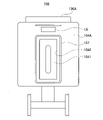
- FIG. 1 is a top view of a railway vehicle according to an embodiment of the present invention
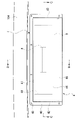
- FIG. FIG. 2 is a cross-sectional view taken along the line AA of FIG. 1
- FIG. 2 is a view of the railcar shown in FIG. 1 as seen from the outside of the first end structure; It is a front view of an exhaust structure.
- FIG. 5 is a cross-sectional view taken along the line BB of FIG. 4;
- FIG. 5 is a cross-sectional view taken along line CC of FIG. 4;
- FIG. 6 is a cross-sectional view taken along line DD of FIG. 5; It is a figure explaining the relationship between the vehicle advancing direction and the flow of outside air.
- FIG. 11 is a diagram for explaining the operation of a closing plate installed on the front end end structure;
- FIG. 11 is a diagram for explaining the operation of a closing plate installed on the rear end end structure; It is a figure explaining the flow of exhaust gas. It is a figure explaining the relationship between the vehicle advancing direction and the flow of outside air.
- FIG. 1 is a top view of a railway vehicle 100 according to an embodiment of the invention.
- the illustration of the roof structure 102 is omitted in order to show the duct structure.
- FIG. 2 is a cross-sectional view taken along line AA of FIG.
- the railway vehicle 100 has a body composed of a hexahedron including an underframe 101, a roof structure 102, first and second side structures 103A and 103B, and first and second end structures 104A and 104B.
- the first and second end structures 104A and 104B are an example of "a pair of end structures".
- the first end structure 104A has a first exhaust structure 1A
- the second end structure 104B has a second exhaust structure 1B.
- the first air conditioner 120A and the second air conditioner 120B are installed on the roof structure 102 and connected to an air conditioning duct 130 arranged between the roof structure 102 and the ceiling panel 108. Air-conditioning duct 130 communicates with vehicle interior 105 .
- Each of the first air conditioner 120A and the second air conditioner 120B includes a return port 122 that takes in air from outside the vehicle and the vehicle interior 105, and a blowout port 123 that blows conditioned air to the air conditioning duct .
- the first and second side structures 103A and 103B are provided with, for example, an opening/closing door 106 and door pockets and side windows (not shown).
- FIG. 3 is a diagram of the railway vehicle 100 shown in FIG. 1 as viewed from the outside of the first end structure 104A.
- the first end structure 104A is provided with a end doorway 1042 opened and closed by a door 1041 at the center in the vehicle width direction.
- the penetrating hood 107 is attached along the outer side of the end doorway 1042.
- the first exhaust structure 1A is arranged above the penetrating hood 107 (above the end doorway 1042).
- the second end structure 104B is configured in the same manner as the first end structure 104A, so the description thereof will be omitted.
- FIG. 5 is a cross-sectional view taken along the line BB of FIG. 4.
- FIG. 6 is a cross-sectional view taken along line CC of FIG. 4.
- FIG. 7 is a cross-sectional view taken along line DD of FIG.
- the exhaust structure 1 mainly includes an exhaust duct 2, a base plate 6, a closing plate 3, and a cover 4.
- the exhaust duct 2 is arranged inside the vehicle and communicates with the vehicle interior 105 .
- the base plate 6 is fixed to the outer surface of the end structure 104 and has an exhaust port 61 for discharging the air in the passenger compartment 105 to the outside of the vehicle.
- the cover 4 is fixed to the end structure 104 so as to cover the periphery of the exhaust port 61 while opening only downward, and forms a flow path 9 that communicates with the exhaust port 61 .
- the closing plate 3 is a member that closes the exhaust port 61 .
- the closing plate 3 is swingably supported by the base plate 6 at its lower end at a position below the exhaust port 61, and is provided so as to swing toward the outside of the vehicle with respect to the end structure 104 by its own weight.
- the exhaust port 61 is an example of an "exhaust port" provided in the end structure.
- the end structure 104 has a structure opening 1043 above the penetrating hood 107 (above the end entrance 1042).
- the exhaust duct 2 is arranged between the roof structure 102 and the ceiling panel 108 to allow the structure opening 1043 and the passenger compartment 105 to communicate with each other.
- One end of the exhaust duct 2 is fixed by welding or the like to the inner surface of the end structure 104 positioned on the passenger compartment 105 side, and the first exhaust duct opening 21 communicates with the structure opening 1043 .
- the other end of the exhaust duct 2 is fixed to the ceiling panel 108 , and the second exhaust duct opening 22 communicates with the vehicle interior 105 .
- the body structure opening 1043 is provided in a horizontally long rectangular shape in the vehicle width direction (horizontal direction in the drawing).
- the first exhaust duct opening 21 is formed in a rectangular shape whose vertical and horizontal dimensions are shorter than those of the structure opening 1043 .
- the base plate 6 has a rectangular shape larger than the structure opening 1043 and is fixed to the end structure 104 so as to block the structure opening 1043 .
- a rectangular exhaust port 61 is formed in the base plate 6 at a position overlapping the first exhaust duct opening 21 .
- the exhaust port 61 is formed with an opening area smaller than that of the first exhaust duct opening 21 .
- the cover 4 is arranged so as to surround the exhaust port 61 in a state of opening only downward, and forms a flow path 9 communicating with the exhaust port 61 .
- the cover 4 includes an upper plate 41 , a pair of side plates 42 and 43 , a front plate 44 and a flange portion 45 .
- the upper plate 41 has a rectangular shape.
- the pair of side plates 42 and 43 are connected to both ends of the upper plate 41 in the longitudinal direction.
- the front plate 44 is connected to front portions of the upper plate 41 and the pair of side plates 42 and 43 located on the side opposite to the end structure 104 .
- the flange portion 45 is provided perpendicular to the top plate 41 and the pair of side plates 42 and 43 along the rear portions of the top plate 41 and the pair of side plates 42 and 43 located on the end structure 104 side.
- the cover 4 is formed with substantially the same dimensions as the outer shape of the base plate 6, and is fixed to the end structure 104 by the fixing member 48 with the flange portion 45 overlapping the base plate 6. Note that the cover 4 and the base plate 6 may be individually fixed to the end structure 104 .
- the cover 4 is provided with a receiver 5 and a plurality of louvers 46.
- the receiving metal 5 is fixed to the inner wall of the front plate 44 by bolts, welding, or the like, and is engaged with the end structure 104 so as to support the closing plate 3 swinging to the outside of the vehicle from below.
- the cover 4 is arranged such that the distance between the front plate 44 and the base plate 6 (end structure 104) is shorter than the dimension of the closing plate 3 in the vertical direction (short side direction). , is provided.
- the cover 4 can reduce the amount of protrusion of the cover 4 from the end structure 104 and reduce air resistance while swinging the closing plate 3 within the cover 4 to open and close the exhaust port 61 .
- FIGS. 5 and 6 when the closing plate 3 swings to the outside of the vehicle with respect to the end structure 104, the cover 4 is mounted so as to bridge between the end structure 104 and the front plate 44. 5 mounting position has been adjusted.
- the plurality of louvers 46 are arranged in the lower opening of the cover 4 and constitute rectifying means for rectifying the outside air entering the flow path 9.
- the plurality of louvers 46 are arranged parallel to the end structure 104 and fixed at both ends to the pair of side plates 42 and 43 .
- the plurality of louvers 46 are oriented so as to guide outside air entering the lower opening of the cover 4 to the front plate 44 .
- the closing plate 3 has a rectangular shape larger than the exhaust port 61 and is attached to the base plate 6 via a pair of hinges 8,8.
- a pair of hinges 8, 8 are coupled to the lower end of the closing plate 3 and the portion of the base plate 6 below the exhaust port 61, respectively.
- the closing plate 3 is connected to the base plate 6 via a pair of hinges 8, 8 at its lower end located below the center of gravity. 61 can be released.
- the base plate 6 has the packing 7 adhered to the surface opposite to the back surface that contacts the end structure 104 .
- the packing 7 is made of an elastic material and is arranged along the vehicle width direction outer edges (left and right outer edges in FIG. 7) and the upper outer edge (upper outer edge in FIG. 7) of the exhaust port 61 .
- the closing plate 3 is engaged with the base plate 6 fixed to the end structure 104 via the packing 7 and closes the exhaust port 61 .
- the closing plate 3 is provided with a pressure receiving concave portion 3a at a position corresponding to the exhaust port 61.
- the closing plate 3 has a pressure-receiving recess 3a formed in a region inside the exhaust port 61 so as to be recessed toward the end structure 104 side. As a result, the closing plate 3 can be swung without causing the pressure-receiving recessed portion 3 a to collide with the base plate 6 , and can be brought into close contact with the packing 7 .
- the pressure-receiving concave portion 3a of the present embodiment is provided so as to have a right-angled triangular shape in a cross section when the closing plate 3 is cut along the short side direction (vertical direction in the drawing). .
- the pressure-receiving recessed portion 3a is arranged so that the right-angled portion is positioned above the center of gravity of the closing plate 3, so that the closing plate 3 can easily swing to the outside of the vehicle with respect to the end structure 104 by its own weight.
- the cross-sectional shape of the pressure-receiving concave portion 3a is not limited to that of the present embodiment, and may be a triangular shape other than a right-angled triangular shape, a rectangular shape, or an arc shape.
- the closing plate 3 of the present embodiment has a rectangular frame 31 with a central opening of a frame 31 fitted with a pressure-receiving recess forming member 32 that forms the pressure-receiving recess 3a, and a fixing member 33. It is formed by combining the two using
- the closing plate 3 has a lateral dimension in the vehicle width direction (horizontal direction in the drawing) that is smaller than the lateral dimension of the cover 4 in the vehicle width direction (the interval between the pair of side plates 42 and 43). A part of the flow path 9 is closed when it is set and locked to the receiving metal 5 . Therefore, when the closing plate 3 is engaged with the receiving metal 5 , the exhaust port 61 is formed between the side plate 42 and the closing plate 3 and between the side plate 43 and the closing plate 3 . It communicates with the lower opening of the cover 4 via the gap 9b.
- the first and second air conditioners 120A and 120B take in air from the outside of the vehicle and the vehicle interior 105 via the return port 122 to generate conditioned air, and air the air from the air outlet 123.
- Feed duct 130 Conditioned air is supplied to vehicle interior 105 from air conditioning duct 130 . Therefore, the pressure in the compartment 105 increases by the amount of the fresh air taken in from the outside of the vehicle. Therefore, the air in the passenger compartment 105 is discharged to the outside of the vehicle through the opening/closing door 106, gaps in the door pocket (not shown), and the first and second exhaust structures 1A and 1B at the same air volume as the fresh air.
- the closing plate 3 is swingably supported by the base plate 6 at its lower end below the center of gravity. Therefore, when the railroad car 100 stops, as shown in FIG. It swings by its own weight, is locked by the receiving metal 5, and opens the exhaust port 61. - ⁇ Thus, the posture of the closing plate 3 that opens the exhaust port 61 is referred to as the "first posture”.
- the railway vehicle 100 exhausts air from the passenger compartment 105 to the outside of the vehicle not only through the opening/closing door 106 and the gaps between the door pockets, but also through the exhaust ports 61 of the first and second end structures 104A and 104B. discharge to Therefore, the railway vehicle 100 can increase the amount of fresh air introduced, and promote ventilation of the passenger compartment 105 .
- the exhaust port 61 is provided above the gable doorway 1042 . Therefore, the railroad vehicle 100 can exhaust air (for example, air near the ceiling panel 108 or near the end structure 104) that cannot be discharged from the opening/closing door 106 or the gap of the door pocket (not shown) to the outside of the vehicle through the exhaust port 61. Ventilation of the entire room 105 can be facilitated.
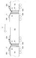
- FIG. 8 is a diagram for explaining the relationship between the vehicle traveling direction X1 and the outside air flow Y1.
- Arrow X1 in FIG. 8 indicates the traveling direction of the train (railway vehicle 100) (hereinafter referred to as "vehicle traveling direction"), and arrow Y1 indicates the flow of outside air as seen from the train (railway vehicle 100).
- a railway vehicle 100 is connected to another railway vehicle 100 via a penetrating hood 107 to form a train.
- the outside air flows around the railway vehicle 100 and the hood 107 in the direction opposite to the vehicle traveling direction X1, as indicated by the arrow Y1 in the figure.
- the outside air flowing in the direction opposite to the vehicle traveling direction X1 along the roof structure 102 of the railroad vehicle 100 in front is directed to the rear side [the direction in which the railroad vehicle travels (here, the vehicle traveling direction X1).
- the side positioned rearward as a reference] turns toward the penetrating hood 107 near the second end structure 104B.
- the front side of the rear railroad vehicle 100 [the direction in which the railroad vehicle travels (here, the vehicle traveling direction X1) is used as a reference. ], and changes the flow direction to the roof structure 102 side.
- the outside air then flows along the roof structure 102 of the railway vehicle 100 behind in the direction opposite to the vehicle traveling direction X1.
- the pressure near the first end structure 104A on the front side is positive, and the pressure near the second end structure 104B on the rear side is negative.
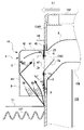
- FIG. 9 is a diagram explaining the operation of the closing plate 3 installed on the first end structure 104A on the front side.
- the outside air that has flowed rearward along the penetrating hood 107 hits the first end structure 104A, changes its direction toward the roof structure 102, and enters the flow path 9 through the lower opening of the cover 4. do.
- Outside air flows toward the front plate 44 by means of the louvers 46,46. After colliding with the front plate 44, the outside air flows toward the closing plate 3 in the first posture.
- the closing plate 3 is pressed toward the first end structure 104A by the wind pressure of the outside air.
- the cover 4 is open only downward. Therefore, the wind pressure acting on the closing plate 3 increases as the railway vehicle 100 accelerates.
- the closing plate 3 swings toward the first end structure 104A at high speed.
- the closing plate 3 is engaged with the first end structure 104A via the packing 7 and closes the exhaust port 61.
- the posture of the closing plate 3 that blocks the exhaust port 61 is referred to as a "second posture". For example, when the vehicle speed reaches 30 to 40 km/h, the closing plate 3 is automatically displaced from the first posture to the second posture by wind pressure.
- the lower end of the closing plate 3 is supported by the base plate 6 via a pair of hinges 8, 8 while slightly overlapping the base plate 6, as shown in FIG. Moreover, the upper end outer edge portion and the left and right outer edge portions of the closing plate 3 are in close contact with the packing 7 . Therefore, the closing plate 3 in the second posture can block the exhaust port 61 without forming a gap around the exhaust port 61, and can prevent outside air and rainwater from flowing into the exhaust port 61. .
- FIG. 10 is a diagram explaining the operation of the closing plate 3 installed on the second end structure 104B on the rear side.
- FIG. 11 is a diagram for explaining the flow Z of exhaust gas.
- the outside air flowing along the roof structure 102 from the first end structure 104A side changes its direction to the cover 4 side of the second exhaust structure 1B at the second end structure 104B on the rear side. . Then, it flows rearward along the penetrating hood 107 .
- the closing plate 3 of the second end structure 104B continues to maintain the first posture even after the railway vehicle 100 starts running due to the amount of exhaust air from the inside of the vehicle and the dead weight of the closing plate 3 .
- the air in the flow path 9 is sucked from below the cover 4 to the outside of the cover 4 .
- the pressure in the flow path 9 becomes lower than the pressure in the vehicle compartment 105, and the air in the vehicle compartment 105 is easily discharged from the exhaust port 61 to the outside of the vehicle.
- gaps 9a and 9b are formed on both sides in the vehicle width direction of the closing plate 3 in the first posture. Therefore, the air discharged from the exhaust port 61 flows below the cover 4 through the gaps 9a and 9b as indicated by the arrow Z in the figure. Since the flow area of the flow path 9 is narrowed by the gaps 9a and 9b, the air discharged from the exhaust port 61 is accelerated by the gaps 9a and 9b and easily flows out of the cover 4.
- the exhaust port 61 on the first end structure 104A side is blocked by the closing plate 3, but the exhaust port 61 on the second end structure 104B side is open. Therefore, even though the door 106 is closed while the railroad car 100 is running, the air in the passenger compartment 105 can be exhausted from one of the exhaust ports 61, and the ventilation of the passenger compartment 105 is promoted.
- the wind pressure acting on the closing plate 3 decreases in the first end structure 104A on the front side.
- the closing plate 3 pivots toward the outside of the vehicle with respect to the first end structure 104A at high speed around the pair of hinges 8, 8, and automatically returns from the second posture to the first posture.
- the closing plate 3 provided on the second end structure 104B side continues to maintain the first posture.
- the second end structure 104B is the front end end structure
- the first end structure 104A is the rear end end structure.
- the closing plate 3 of the second exhaust structure 1B provided on the second end structure 104B is in the second position
- the first exhaust structure 1A provided on the first end structure 104A is in the second position.
- the closing plate 3 is in the first posture. Since this operation is the same as when the railroad vehicle 100 runs in the vehicle traveling direction X1, the description thereof is omitted.
- the inventors conducted an experiment using an actual vehicle having a configuration similar to that of the railroad vehicle 100 to confirm whether outside air flows into the exhaust port 61 during running of the vehicle. Experiments visualized the air flow in the cabin 105 using the tuft method (visible threads) or smoke. A video camera was installed in the passenger compartment 105 to photograph and record the visualized air flow. As a result, it was confirmed that outside air did not flow into the passenger compartment 105 when the vehicle was stopped and when the vehicle was running.
- the railroad car 100 of the present embodiment reaches a position where the closing plates 3 provided on the first and second end structures 104A and 104B are locked to the cover 4 by their own weight while the car is stopped. It swings to open the exhaust port 61 .
- the closing plate 3 of the first end structure 104A (the second end structure 104B) on the front side [the side located in the direction of travel X1 (X2) of the vehicle] is pushed down by the wind pressure. It swings to the (second end structure 104B) side and closes the exhaust port 61.
- the railway vehicle 100 uses the dead weight of the closing plate and the wind pressure to open the exhaust port 61 in at least one of the first end structure 104A and the second end structure 104B without using power.
- the cover 4 covers the periphery of the exhaust port 61 in a state of opening only downward, it is difficult for rainwater to flow into the opened exhaust port 61.
- the closing plate 3 blocks the exhaust port 61 with wind pressure, so that outside air and rainwater do not flow into the exhaust port 61.
- the second end structure 104B first end structure 104A
- the closing plate 3 is suspended between the end structure 104 and the cover 4 at a position below the exhaust port 61, and the flow passage 9 is closed.
- the air in the vehicle compartment 105 can be discharged from the exhaust port 61 to the outside of the vehicle while suppressing the rainwater entering the cover 4 from flowing into the exhaust port 61.
- ventilation of the passenger compartment 105 can be promoted without using power, and outside air and rainwater can be prevented from entering the exhaust port 61 during travel.
- the present invention can be applied in various ways without being limited to the above embodiments.
- the railway vehicle of the present invention may be applied to express trains and the like.
- the closing plate 3 does not have to have the pressure receiving concave portion 3a. However, if the pressure receiving recess 3a is provided in the closing plate 3 as in the above embodiment, the pressure receiving area where the wind pressure of the outside air acts on the closing plate 3 is increased by the pressure receiving recess 3a. This makes it easier for the closing plate 3 of the first end structure 104A (second end structure 104B) on the front side to close the exhaust port 61 with wind pressure after the railroad car 100 starts running.
- the number of louvers 46 may be one. Also, the louver 46 may be omitted.
- the cover 4 by providing the cover 4 with the louver 46 so as to rectify the outside air entering the flow path 9 from below the cover 4 toward the inner wall of the cover 4 (front plate 44), the cover 4 Rainwater entering the flow path 9 from below hits the inner wall of the cover 4 (front plate 44) and is removed from the outside air. Therefore, it becomes difficult for rainwater to flow into the exhaust port 61 .
- the exhaust port 61 may be provided on the side of the penetrating hood 107 (end entrance 1042). However, when the exhaust port 61 is provided above the penetrating hood 107 (above the end doorway 1042) as in the above embodiment, when the railroad vehicle 100 starts running, the outside air flowing along the penetrating hood 107 will flow from below the cover 4. It becomes easy to enter and swing the closing plate 3 by wind pressure.
- the cover plate 3 may be locked by the front plate 44 of the cover 4 without the receiving metal 5 . However, by providing the cover 4 with the receiving metal 5, the friction between the closing plate 3 and the cover 4 can be reduced, and the closing plate 3 can be swung smoothly.
- the receiver 5 may be attached to both or one of the inner walls of the pair of side plates 42 and 43 . However, if the cover plate 3 is locked to the cover plate 5 by fixing the cover plate 5 to the front plate 44 and arranging it on the swinging path of the cover plate 3 as in the above embodiment, the The air gaps 9a and 9b are wide enough to improve the exhaust efficiency.
- the shape of the cover 4 is not limited to the above embodiment, and for example, the connecting portion between the upper plate 41 and the front plate 44 may be formed in an arc shape. Also, a rear plate may be provided at the rear portion of the cover 4 . However, even if the cover 4 does not have a surface facing the front plate 44 as in the above embodiment, the flow path 9 can be formed between the cover 4 and the end structure 104 by being fixed to the end structure 104 . According to this, an extra level difference is not formed in the vicinity of the lower opening of the cover 4, and outside air hitting the end structure 104 can enter the cover 4 smoothly.
- the exhaust duct 2 may communicate with the vehicle compartment 105 via an exhaust fan. Even when the exhaust fan is operating, if the vehicle speed is high, the wind pressure acting on the end structure 104 increases, and there is a risk that outside air or rainwater may flow into the exhaust port 61 . However, by providing the closing plate 3 and the cover 4 as in the above embodiment, it is possible to prevent outside air and rainwater from flowing into the exhaust port 61 .
- the closing plate 3 may be formed by one component. However, by separately forming the frame body 31 and the pressure-receiving recess forming member 32 as in the above-described embodiment, it is possible to reduce the labor for processing the closing plate 3 .
- a filter for preventing entry of insects or the like may be installed on the exhaust duct 2 side of 61 .
Landscapes
- Engineering & Computer Science (AREA)
- Mechanical Engineering (AREA)
- Air-Conditioning For Vehicles (AREA)
- Cooling, Air Intake And Gas Exhaust, And Fuel Tank Arrangements In Propulsion Units (AREA)
Priority Applications (2)
| Application Number | Priority Date | Filing Date | Title |
|---|---|---|---|
| JP2022576929A JP7545495B2 (ja) | 2021-01-25 | 2021-01-25 | 鉄道車両 |
| PCT/JP2021/002395 WO2022157964A1 (ja) | 2021-01-25 | 2021-01-25 | 鉄道車両 |
Applications Claiming Priority (1)
| Application Number | Priority Date | Filing Date | Title |
|---|---|---|---|
| PCT/JP2021/002395 WO2022157964A1 (ja) | 2021-01-25 | 2021-01-25 | 鉄道車両 |
Publications (1)
| Publication Number | Publication Date |
|---|---|
| WO2022157964A1 true WO2022157964A1 (ja) | 2022-07-28 |
Family
ID=82548640
Family Applications (1)
| Application Number | Title | Priority Date | Filing Date |
|---|---|---|---|
| PCT/JP2021/002395 Ceased WO2022157964A1 (ja) | 2021-01-25 | 2021-01-25 | 鉄道車両 |
Country Status (2)
| Country | Link |
|---|---|
| JP (1) | JP7545495B2 (https=) |
| WO (1) | WO2022157964A1 (https=) |
Citations (3)
| Publication number | Priority date | Publication date | Assignee | Title |
|---|---|---|---|---|
| JPH0635853Y2 (ja) * | 1987-11-18 | 1994-09-21 | 株式会社日立製作所 | 車両用圧力緩和装置 |
| KR20080030987A (ko) * | 2008-03-18 | 2008-04-07 | 주식회사 이플러스티 | 철도 차량용 자연급기 방식 환기 장치 |
| CN106739953A (zh) * | 2016-11-29 | 2017-05-31 | 北京汽车研究总院有限公司 | 一种汽车侧通风格栅及汽车 |
-
2021
- 2021-01-25 WO PCT/JP2021/002395 patent/WO2022157964A1/ja not_active Ceased
- 2021-01-25 JP JP2022576929A patent/JP7545495B2/ja active Active
Patent Citations (3)
| Publication number | Priority date | Publication date | Assignee | Title |
|---|---|---|---|---|
| JPH0635853Y2 (ja) * | 1987-11-18 | 1994-09-21 | 株式会社日立製作所 | 車両用圧力緩和装置 |
| KR20080030987A (ko) * | 2008-03-18 | 2008-04-07 | 주식회사 이플러스티 | 철도 차량용 자연급기 방식 환기 장치 |
| CN106739953A (zh) * | 2016-11-29 | 2017-05-31 | 北京汽车研究总院有限公司 | 一种汽车侧通风格栅及汽车 |
Also Published As
| Publication number | Publication date |
|---|---|
| JP7545495B2 (ja) | 2024-09-04 |
| JPWO2022157964A1 (https=) | 2022-07-28 |
Similar Documents
| Publication | Publication Date | Title |
|---|---|---|
| JP7128251B2 (ja) | 川又は海を貫く地下鉄における区間が長く且つ大きいトンネルの火災換気排煙装置及び方法 | |
| JPH04505304A (ja) | 自動車、特に、バスに対する空気調和装置 | |
| JP2012071680A (ja) | 給気装置と排気装置と排気送風機とを備える鉄道車両、および、鉄道車両に備えられる給気装置と排気装置と排気送風機の制御方法 | |
| JP3116874B2 (ja) | 空気調和装置の空気吹出口構造 | |
| PT2239177T (pt) | Método para o funcionamento de um veículo de caminho de ferro em caso de incêndio e veículo de caminho de ferro para isso construído | |
| CN110284818A (zh) | 一种单向通风装置 | |
| WO2022157964A1 (ja) | 鉄道車両 | |
| JP2004077113A (ja) | エアシャッタ及びその設置方法 | |
| KR101732405B1 (ko) | 열차풍을 이용한 승강장 배기장치 | |
| JP2006001401A (ja) | 車両用エアシャッタ | |
| KR20130026136A (ko) | 철도차량 객실환기용 공기 출입구 개폐 댐퍼 | |
| JP2012106589A (ja) | 鉄道車両用空調装置 | |
| JP4712457B2 (ja) | 風除室、および風除室において室内と室外の間の空気の流れを低減する方法 | |
| JP7789033B2 (ja) | 鉄道車両の窓構造とそれを有する鉄道車両 | |
| JP2013203363A (ja) | 車両の車体前部構造 | |
| JP7669531B2 (ja) | 吸排気装置および吸排気装置を備える鉄道車両 | |
| JP5214957B2 (ja) | 編成列車 | |
| JP2022020250A (ja) | 鉄道車両の窓構造 | |
| US1308737A (en) | harrison | |
| JP2012086587A (ja) | 鉄道車両 | |
| US500555A (en) | Deflector and ventilator for passenger-cars | |
| CN112610265B (zh) | 短间距密集站点的多车站协同通风排烟系统及控制方法 | |
| US1720858A (en) | Ventilating door for railway cars and the like | |
| JPH06144222A (ja) | 高速車両用通風装置 | |
| KR20210070072A (ko) | 철도차량 객실용 에어커튼 |
Legal Events
| Date | Code | Title | Description |
|---|---|---|---|
| 121 | Ep: the epo has been informed by wipo that ep was designated in this application |
Ref document number: 21921072 Country of ref document: EP Kind code of ref document: A1 |
|
| ENP | Entry into the national phase |
Ref document number: 2022576929 Country of ref document: JP Kind code of ref document: A |
|
| NENP | Non-entry into the national phase |
Ref country code: DE |
|
| 122 | Ep: pct application non-entry in european phase |
Ref document number: 21921072 Country of ref document: EP Kind code of ref document: A1 |