WO2022154124A1 - 玉軸受用冠型保持器、及び玉軸受 - Google Patents
玉軸受用冠型保持器、及び玉軸受 Download PDFInfo
- Publication number
- WO2022154124A1 WO2022154124A1 PCT/JP2022/001445 JP2022001445W WO2022154124A1 WO 2022154124 A1 WO2022154124 A1 WO 2022154124A1 JP 2022001445 W JP2022001445 W JP 2022001445W WO 2022154124 A1 WO2022154124 A1 WO 2022154124A1
- Authority
- WO
- WIPO (PCT)
- Prior art keywords
- cage
- ball
- circumferential
- claw
- main portion
- Prior art date
- Legal status (The legal status is an assumption and is not a legal conclusion. Google has not performed a legal analysis and makes no representation as to the accuracy of the status listed.)
- Ceased
Links
Images









Classifications
-
- F—MECHANICAL ENGINEERING; LIGHTING; HEATING; WEAPONS; BLASTING
- F16—ENGINEERING ELEMENTS AND UNITS; GENERAL MEASURES FOR PRODUCING AND MAINTAINING EFFECTIVE FUNCTIONING OF MACHINES OR INSTALLATIONS; THERMAL INSULATION IN GENERAL
- F16C—SHAFTS; FLEXIBLE SHAFTS; ELEMENTS OR CRANKSHAFT MECHANISMS; ROTARY BODIES OTHER THAN GEARING ELEMENTS; BEARINGS
- F16C33/00—Parts of bearings; Special methods for making bearings or parts thereof
- F16C33/30—Parts of ball or roller bearings
- F16C33/38—Ball cages
- F16C33/41—Ball cages comb-shaped
- F16C33/412—Massive or moulded comb cages, e.g. snap ball cages
- F16C33/414—Massive or moulded comb cages, e.g. snap ball cages formed as one-piece cages, i.e. monoblock comb cages
- F16C33/416—Massive or moulded comb cages, e.g. snap ball cages formed as one-piece cages, i.e. monoblock comb cages made from plastic, e.g. injection moulded comb cages
-
- F—MECHANICAL ENGINEERING; LIGHTING; HEATING; WEAPONS; BLASTING
- F16—ENGINEERING ELEMENTS AND UNITS; GENERAL MEASURES FOR PRODUCING AND MAINTAINING EFFECTIVE FUNCTIONING OF MACHINES OR INSTALLATIONS; THERMAL INSULATION IN GENERAL
- F16C—SHAFTS; FLEXIBLE SHAFTS; ELEMENTS OR CRANKSHAFT MECHANISMS; ROTARY BODIES OTHER THAN GEARING ELEMENTS; BEARINGS
- F16C33/00—Parts of bearings; Special methods for making bearings or parts thereof
- F16C33/30—Parts of ball or roller bearings
- F16C33/38—Ball cages
- F16C33/41—Ball cages comb-shaped
- F16C33/418—Details of individual pockets, e.g. shape or ball retaining means
-
- F—MECHANICAL ENGINEERING; LIGHTING; HEATING; WEAPONS; BLASTING
- F16—ENGINEERING ELEMENTS AND UNITS; GENERAL MEASURES FOR PRODUCING AND MAINTAINING EFFECTIVE FUNCTIONING OF MACHINES OR INSTALLATIONS; THERMAL INSULATION IN GENERAL
- F16C—SHAFTS; FLEXIBLE SHAFTS; ELEMENTS OR CRANKSHAFT MECHANISMS; ROTARY BODIES OTHER THAN GEARING ELEMENTS; BEARINGS
- F16C19/00—Bearings with rolling contact, for exclusively rotary movement
- F16C19/02—Bearings with rolling contact, for exclusively rotary movement with bearing balls essentially of the same size in one or more circular rows
- F16C19/04—Bearings with rolling contact, for exclusively rotary movement with bearing balls essentially of the same size in one or more circular rows for radial load mainly
- F16C19/06—Bearings with rolling contact, for exclusively rotary movement with bearing balls essentially of the same size in one or more circular rows for radial load mainly with a single row or balls
-
- F—MECHANICAL ENGINEERING; LIGHTING; HEATING; WEAPONS; BLASTING
- F16—ENGINEERING ELEMENTS AND UNITS; GENERAL MEASURES FOR PRODUCING AND MAINTAINING EFFECTIVE FUNCTIONING OF MACHINES OR INSTALLATIONS; THERMAL INSULATION IN GENERAL
- F16C—SHAFTS; FLEXIBLE SHAFTS; ELEMENTS OR CRANKSHAFT MECHANISMS; ROTARY BODIES OTHER THAN GEARING ELEMENTS; BEARINGS
- F16C2208/00—Plastics; Synthetic resins, e.g. rubbers
- F16C2208/20—Thermoplastic resins
- F16C2208/60—Polyamides [PA]
Definitions
- the crown type cage 10 is made of, for example, a resin material such as nylon 46 (polyamide 46, PA46), nylon 66 (polyamide 66, PA66), polyamide 9T (PA9T), polyamide 10T (PA10T), L-PPS, PEEK, etc. Alternatively, it is made of another resin material. Further, in order to improve the strength of the cage 10, a resin composition to which several tens of percent (for example, 10 to 50 wt%) of fibrous reinforcing material (carbon fiber, glass fiber, aramid fiber, etc.) is added may be used. Examples of the method for manufacturing the cage 10 include a method of injection molding using a mold and a method of manufacturing with a 3D printer.
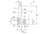
- the pillar portion 30 has a pair of claw portions 31, 31 and a connecting portion 33 connecting the pair of claw portions 31, 31.
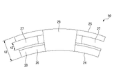
- the cage 10 can be easily removed from the mold during injection molding as compared with the case where the opening 27 is composed of a simple flat surface. ..
- the cage 10 of the present embodiment D1 ⁇ D2, t1 ⁇ (t2 / 2), H1 ⁇ (H2 / 2) are satisfied, and the opening 27 is formed.
- the weight of the cage 10 is reduced, and deformation due to centrifugal force during high-speed rotation can be suppressed. Therefore, it is possible to prevent the cage 10 from coming into contact with the outer ring 5, the shield plate 7, and the like, and it is possible to suppress wear, vibration, and heat generation of the cage 10.
- the claw portion 31 and the opening 27 are provided so as to be offset in the radial direction, and the opening 27 is located radially outside the claw portion 31.
- the effect of suppressing stress and deformation generated by centrifugal force is not so different from that of the first embodiment, but the cage 50 has the inner ring 3, the outer ring 5, and the cage 50. It is effective when incorporated into a bearing 1 composed of balls 6. That is, as will be described later, the strain generated in the claw portion 31 of the cage 50 is reduced.
Landscapes
- Engineering & Computer Science (AREA)
- General Engineering & Computer Science (AREA)
- Mechanical Engineering (AREA)
- Rolling Contact Bearings (AREA)
Abstract
Description
(1) 円環状の主部と、
前記主部から周方向に所定の間隔で軸方向に突出する複数の柱部と、
隣り合う前記柱部の間に形成され、玉を保持可能な球面形状の球状凹面を有するポケットと、
を備える、玉軸受用冠型保持器であって、
前記柱部は、先端部が互いに間隔をあけて配置される一対の爪部と、前記一対の爪部を接続する接続部を有し、
前記ポケットを構成する隣り合う二つの前記爪部の先端部同士の間には、前記玉の直径より短い幅を有し、かつ、前記玉を挿入するための、入口部が設けられ、
前記ポケットの前記球状凹面の曲率半径は、前記玉の転動面の曲率半径よりも大きく、 前記爪部の外径D1は、前記主部の外径D2よりも小さく、
前記爪部の径方向幅t1は、前記主部の径方向幅t2の1/2以下であり、
前記柱部の前記接続部の上面から前記主部の底面までの軸方向幅H1は、前記玉軸受用冠型保持器の軸方向幅H2の1/2以下であり、
前記主部には、隣り合う前記ポケットの間に軸方向に開口した開口部が設けられ、前記爪部と前記開口部とは径方向においてオフセットして設けられ、前記開口部が爪部よりも径方向外側に位置する
ことを特徴とする玉軸受用冠型保持器。
(2) 前記柱部の前記接続部の上面から前記主部の底面までの軸方向幅H1は、前記ポケットの底部における前記主部の軸方向幅H3よりも大きい
(1)に記載の玉軸受用冠型保持器。
(3) 前記主部の底面は、隣り合う前記開口部の間において、軸方向に突出する凸部を有する
(1)または(2)に記載の玉軸受用冠型保持器。
(4) 前記凸部が設けられる径方向範囲及び周方向範囲は、前記ポケットを構成する前記主部の前記球状凹面が設けられる径方向範囲及び周方向範囲と略同一である
(3)に記載の玉軸受用冠型保持器。
(5) 前記爪部の径方向幅は、前記主部側から前記爪部の先端部側に向かうほど小さくなる、
(1)~(4)のいずれか一項に記載の玉軸受用冠型保持器。
(6) 前記爪部は、前記ポケットを構成する周方向第一面と、前記周方向第一面とは反対側の周方向第二面と、を有し、
(1)~(5)のいずれか一項に記載の玉軸受用冠型保持器。
(7) 外輪と、
内輪と、
前記外輪の軌道輪と、前記内輪の軌道面と、の間に配置された複数の玉と、
(1)~(6)のいずれか1項に記載の玉軸受用冠型保持器と、
を備える、玉軸受。
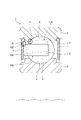
図1~4に示すように、本実施形態の玉軸受用冠型保持器(以下、「冠型保持器」、又は単に「保持器」とも称す)10は、図15~16に示す従来の保持器100と同様に、図14に示す玉軸受1に適用される。
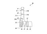
図5~7には、第二実施形態に係る保持器50が開示されている。本実施形態の保持器50は、主部20の底面26に凸部28が設けられる構成が、第一実施形態の保持器50と異なる。その他の構成は、上記実施形態と同一であるので、図面に符号を付すことでその説明を省略する。
図8には、第三実施形態に係る保持器60が開示されている。本実施形態の保持器60は、爪部31の径方向寸法が、上記実施形態の保持器60と異なる。その他の構成は、上記実施形態と同一であるので、図面に符号を付すことでその説明を省略する。
図9には、第四実施形態に係る保持器70が開示されている。本実施形態の保持器70は、ポケット40を構成する隣り合う二つの爪部31,31の周方向第二面31C,31Cの間の周方向距離が、第一実施形態の保持器70と異なる。その他の構成は、上記実施形態と同一であるので、図面に符号を付すことでその説明を省略する。
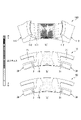
本発明の効果を確かめるために、有限要素法による解析を実施した。解析対象の保持器10,50は、内径:35mmの軸受に使用される冠型樹脂保持器である。従来の冠型樹脂保持器を基準に、本発明の実施形態に基づき、形状を設定した。すなわち、図10(a)~(c)に示すように、(a)従来品としては図15~16に示した保持器100を採用し、(b)実施例1としては図1~4に示した第一実施形態の保持器10を採用し、(c)実施例2としては図5~7に示した第二実施形態の保持器50を採用した。
2 内輪軌道
3 内輪
4 外輪軌道
5 外輪
6 玉
7 シールド板
10 玉軸受用冠型保持器
20 主部
21 上面
23 球状凹面
24 内周面
25 外周面
26 底面
28 凸部
27 開口部
30 柱部
31 爪部
31A 先端部
31B 周方向第一面
31C 周方向第二面
31D 外周面
31E 内周面
33 接続部
33A 上面
40 ポケット
41 入口部
50,60,70 保持器
Claims (7)
- 円環状の主部と、
前記主部から周方向に所定の間隔で軸方向に突出する複数の柱部と、
隣り合う前記柱部の間に形成され、玉を保持可能な球面形状の球状凹面を有するポケットと、
を備える、玉軸受用冠型保持器であって、
前記柱部は、先端部が互いに間隔をあけて配置される一対の爪部と、前記一対の爪部を接続する接続部を有し、
前記ポケットを構成する隣り合う二つの前記爪部の先端部同士の間には、前記玉の直径より短い幅を有し、かつ、前記玉を挿入するための、入口部が設けられ、
前記ポケットの前記球状凹面の曲率半径は、前記玉の転動面の曲率半径よりも大きく、
前記爪部の外径D1は、前記主部の外径D2よりも小さく、
前記爪部の径方向幅t1は、前記主部の径方向幅t2の1/2以下であり、
前記柱部の前記接続部の上面から前記主部の底面までの軸方向幅H1は、前記玉軸受用冠型保持器の軸方向幅H2の1/2以下であり、
前記主部には、隣り合う前記ポケットの間に軸方向に開口した開口部が設けられ、前記爪部と前記開口部とは径方向においてオフセットして設けられ、前記開口部が爪部よりも径方向外側に位置する
ことを特徴とする玉軸受用冠型保持器。 - 前記柱部の前記接続部の上面から前記主部の底面までの軸方向幅H1は、前記ポケットの底部における前記主部の軸方向幅H3よりも大きい
請求項1に記載の玉軸受用冠型保持器。 - 前記主部の底面は、隣り合う前記開口部の間において、軸方向に突出する凸部を有する請求項1または2に記載の玉軸受用冠型保持器。
- 前記凸部が設けられる径方向範囲及び周方向範囲は、前記ポケットを構成する前記主部の前記球状凹面が設けられる径方向範囲及び周方向範囲と略同一である
請求項3に記載の玉軸受用冠型保持器。 - 前記爪部の径方向幅は、前記主部側から前記爪部の先端部側に向かうほど小さくなる、請求項1~4のいずれか一項に記載の玉軸受用冠型保持器。
- 前記爪部は、前記ポケットを構成する周方向第一面と、前記周方向第一面とは反対側の周方向第二面と、を有し、
前記ポケットを構成する隣り合う二つの前記爪部において、二つの前記周方向第二面の間の周方向距離は、前記主部側から前記爪部の先端部側に向かうほど小さくなる
請求項1~5のいずれか一項に記載の玉軸受用冠型保持器。 - 外輪と、
内輪と、
前記外輪と、前記内輪と、の間に配置された複数の前記玉と、
請求項1~6のいずれか1項に記載の玉軸受用冠型保持器と、
を備える、玉軸受。
Priority Applications (4)
| Application Number | Priority Date | Filing Date | Title |
|---|---|---|---|
| US18/272,695 US12590605B2 (en) | 2021-01-18 | 2022-01-17 | Crown-type retainer for ball bearings, and ball bearing |
| JP2022548218A JP7420274B2 (ja) | 2021-01-18 | 2022-01-17 | 玉軸受用冠型保持器、及び玉軸受 |
| DE112022000678.1T DE112022000678T5 (de) | 2021-01-18 | 2022-01-17 | Kronenförmiger Kugellagerkäfig und Kugellager |
| CN202280010671.9A CN116745540A (zh) | 2021-01-18 | 2022-01-17 | 滚珠轴承用冠型保持架以及滚珠轴承 |
Applications Claiming Priority (2)
| Application Number | Priority Date | Filing Date | Title |
|---|---|---|---|
| JP2021-005913 | 2021-01-18 | ||
| JP2021005913 | 2021-01-18 |
Publications (1)
| Publication Number | Publication Date |
|---|---|
| WO2022154124A1 true WO2022154124A1 (ja) | 2022-07-21 |
Family
ID=82448201
Family Applications (1)
| Application Number | Title | Priority Date | Filing Date |
|---|---|---|---|
| PCT/JP2022/001445 Ceased WO2022154124A1 (ja) | 2021-01-18 | 2022-01-17 | 玉軸受用冠型保持器、及び玉軸受 |
Country Status (5)
| Country | Link |
|---|---|
| US (1) | US12590605B2 (ja) |
| JP (1) | JP7420274B2 (ja) |
| CN (1) | CN116745540A (ja) |
| DE (1) | DE112022000678T5 (ja) |
| WO (1) | WO2022154124A1 (ja) |
Cited By (2)
| Publication number | Priority date | Publication date | Assignee | Title |
|---|---|---|---|---|
| JP7627813B1 (ja) * | 2023-08-09 | 2025-02-06 | ミネベアミツミ株式会社 | 保持器及び該保持器を備える転がり軸受 |
| WO2025033257A1 (ja) * | 2023-08-09 | 2025-02-13 | ミネベアミツミ株式会社 | 保持器及び該保持器を備える転がり軸受 |
Families Citing this family (3)
| Publication number | Priority date | Publication date | Assignee | Title |
|---|---|---|---|---|
| DE102024129979A1 (de) | 2024-10-16 | 2026-04-16 | Schaeffler Technologies AG & Co. KG | Kugellager, Elektromotor und Verfahren zum Betrieb eines Kugellagers |
| DE102024129988A1 (de) | 2024-10-16 | 2026-04-16 | Schaeffler Technologies AG & Co. KG | Set an Kugellagern |
| DE102024129985A1 (de) | 2024-10-16 | 2026-04-16 | Schaeffler Technologies AG & Co. KG | Kugellager, Verwendung eines Kugellagers und Verfahren zum Betrieb eines Kugellagers |
Citations (6)
| Publication number | Priority date | Publication date | Assignee | Title |
|---|---|---|---|---|
| JP2002147463A (ja) * | 2000-11-13 | 2002-05-22 | Nsk Ltd | 冠型保持器 |
| JP2010060001A (ja) * | 2008-09-02 | 2010-03-18 | Jtekt Corp | 転がり軸受用保持器 |
| JP2010516967A (ja) * | 2007-01-26 | 2010-05-20 | アクティエボラゲット・エスコーエッフ | ボールベアリングのためのハウジング |
| JP2016169766A (ja) * | 2015-03-11 | 2016-09-23 | Ntn株式会社 | 軸受用保持器および軸受 |
| JP2018044602A (ja) * | 2016-09-14 | 2018-03-22 | 日本精工株式会社 | 冠型保持器及び玉軸受 |
| KR102045291B1 (ko) * | 2018-11-29 | 2019-11-15 | 셰플러코리아(유) | 원심력에 대한 개선된 변형 저항을 가지는 볼 베어링용 케이지 |
Family Cites Families (4)
| Publication number | Priority date | Publication date | Assignee | Title |
|---|---|---|---|---|
| FR2900996B1 (fr) | 2006-05-12 | 2008-08-08 | Skf Ab | Cage pour roulement a billes |
| JP2008274977A (ja) | 2007-04-25 | 2008-11-13 | Nsk Ltd | 合成樹脂製冠型保持器及び転がり軸受 |
| JP7273629B2 (ja) | 2019-06-25 | 2023-05-15 | 株式会社東芝 | 電力変換装置 |
| US11078959B1 (en) * | 2020-06-10 | 2021-08-03 | Schaeffler Technologies AG & Co. KG | High speed bearing with single piece wide plastic cage |
-
2022
- 2022-01-17 DE DE112022000678.1T patent/DE112022000678T5/de active Pending
- 2022-01-17 WO PCT/JP2022/001445 patent/WO2022154124A1/ja not_active Ceased
- 2022-01-17 JP JP2022548218A patent/JP7420274B2/ja active Active
- 2022-01-17 US US18/272,695 patent/US12590605B2/en active Active
- 2022-01-17 CN CN202280010671.9A patent/CN116745540A/zh active Pending
Patent Citations (6)
| Publication number | Priority date | Publication date | Assignee | Title |
|---|---|---|---|---|
| JP2002147463A (ja) * | 2000-11-13 | 2002-05-22 | Nsk Ltd | 冠型保持器 |
| JP2010516967A (ja) * | 2007-01-26 | 2010-05-20 | アクティエボラゲット・エスコーエッフ | ボールベアリングのためのハウジング |
| JP2010060001A (ja) * | 2008-09-02 | 2010-03-18 | Jtekt Corp | 転がり軸受用保持器 |
| JP2016169766A (ja) * | 2015-03-11 | 2016-09-23 | Ntn株式会社 | 軸受用保持器および軸受 |
| JP2018044602A (ja) * | 2016-09-14 | 2018-03-22 | 日本精工株式会社 | 冠型保持器及び玉軸受 |
| KR102045291B1 (ko) * | 2018-11-29 | 2019-11-15 | 셰플러코리아(유) | 원심력에 대한 개선된 변형 저항을 가지는 볼 베어링용 케이지 |
Cited By (2)
| Publication number | Priority date | Publication date | Assignee | Title |
|---|---|---|---|---|
| JP7627813B1 (ja) * | 2023-08-09 | 2025-02-06 | ミネベアミツミ株式会社 | 保持器及び該保持器を備える転がり軸受 |
| WO2025033257A1 (ja) * | 2023-08-09 | 2025-02-13 | ミネベアミツミ株式会社 | 保持器及び該保持器を備える転がり軸受 |
Also Published As
| Publication number | Publication date |
|---|---|
| US12590605B2 (en) | 2026-03-31 |
| CN116745540A (zh) | 2023-09-12 |
| JPWO2022154124A1 (ja) | 2022-07-21 |
| DE112022000678T5 (de) | 2023-11-02 |
| JP7420274B2 (ja) | 2024-01-23 |
| US20240077109A1 (en) | 2024-03-07 |
Similar Documents
| Publication | Publication Date | Title |
|---|---|---|
| JP7420274B2 (ja) | 玉軸受用冠型保持器、及び玉軸受 | |
| JP5436204B2 (ja) | ボール軸受のための保持器及びころがり軸受組立体 | |
| CN103688069B (zh) | 球轴承用的合成树脂制保持器以及球轴承 | |
| US8292512B2 (en) | Ball bearing and supporting construction | |
| JP6055357B2 (ja) | 円錐ころ軸受用樹脂製保持器 | |
| KR102013084B1 (ko) | 원추 롤러 베어링 및 원추 롤러 베어링의 제조 방법 | |
| CN112739923B (zh) | 滚珠轴承用保持架及滚动轴承 | |
| JP7543660B2 (ja) | 玉軸受用冠型保持器、及び玉軸受 | |
| JP2008286319A (ja) | クリーナモータ軸受用合成樹脂製冠型保持器、クリーナモータ用転がり軸受 | |
| JP5228654B2 (ja) | 円すいころ軸受用保持器及び円すいころ軸受 | |
| JP5029733B2 (ja) | 玉軸受 | |
| WO2023199646A1 (ja) | 玉軸受用冠型保持器、及び玉軸受 | |
| US20250264132A1 (en) | Crown-type retainer for ball bearing, and ball bearing | |
| JPH1151061A (ja) | ころ軸受用合成樹脂製保持器 | |
| WO2014115821A1 (ja) | 円すいころ軸受 | |
| JP2013036608A (ja) | 冠形保持器及び転がり軸受 | |
| JP2008164094A (ja) | 深溝玉軸受 | |
| JP4605099B2 (ja) | 深溝玉軸受 | |
| CN118946743A (zh) | 保持器以及深沟球轴承 | |
| JP2008128296A (ja) | ラジアル玉軸受用合成樹脂製冠型保持器及びラジアル玉軸受 | |
| JP2013117312A (ja) | 円すいころ軸受用保持器及び円すいころ軸受 | |
| US12467501B2 (en) | Crown-shaped retainer for ball bearing, and ball bearing | |
| JP2013117238A (ja) | 玉軸受用保持器および玉軸受 | |
| WO2020059829A1 (ja) | 玉軸受用保持器および転がり軸受 | |
| JP2007127199A (ja) | 転がり軸受用保持器及び転がり軸受 |
Legal Events
| Date | Code | Title | Description |
|---|---|---|---|
| ENP | Entry into the national phase |
Ref document number: 2022548218 Country of ref document: JP Kind code of ref document: A |
|
| 121 | Ep: the epo has been informed by wipo that ep was designated in this application |
Ref document number: 22739529 Country of ref document: EP Kind code of ref document: A1 |
|
| WWE | Wipo information: entry into national phase |
Ref document number: 18272695 Country of ref document: US |
|
| WWE | Wipo information: entry into national phase |
Ref document number: 202280010671.9 Country of ref document: CN |
|
| WWE | Wipo information: entry into national phase |
Ref document number: 112022000678 Country of ref document: DE |
|
| 122 | Ep: pct application non-entry in european phase |
Ref document number: 22739529 Country of ref document: EP Kind code of ref document: A1 |
|
| WWG | Wipo information: grant in national office |
Ref document number: 18272695 Country of ref document: US |