WO2022153850A1 - ワイヤハーネス - Google Patents
ワイヤハーネス Download PDFInfo
- Publication number
- WO2022153850A1 WO2022153850A1 PCT/JP2021/048425 JP2021048425W WO2022153850A1 WO 2022153850 A1 WO2022153850 A1 WO 2022153850A1 JP 2021048425 W JP2021048425 W JP 2021048425W WO 2022153850 A1 WO2022153850 A1 WO 2022153850A1
- Authority
- WO
- WIPO (PCT)
- Prior art keywords
- electromagnetic shield
- metal layer
- shield member
- peripheral surface
- tubular member
- Prior art date
- Legal status (The legal status is an assumption and is not a legal conclusion. Google has not performed a legal analysis and makes no representation as to the accuracy of the status listed.)
- Ceased
Links
Images



Classifications
-
- B—PERFORMING OPERATIONS; TRANSPORTING
- B60—VEHICLES IN GENERAL
- B60R—VEHICLES, VEHICLE FITTINGS, OR VEHICLE PARTS, NOT OTHERWISE PROVIDED FOR
- B60R16/00—Electric or fluid circuits specially adapted for vehicles and not otherwise provided for; Arrangement of elements of electric or fluid circuits specially adapted for vehicles and not otherwise provided for
- B60R16/02—Electric or fluid circuits specially adapted for vehicles and not otherwise provided for; Arrangement of elements of electric or fluid circuits specially adapted for vehicles and not otherwise provided for electric constitutive elements
- B60R16/0207—Wire harnesses
- B60R16/0215—Protecting, fastening and routing means therefor
-
- H—ELECTRICITY
- H01—ELECTRIC ELEMENTS
- H01B—CABLES; CONDUCTORS; INSULATORS; SELECTION OF MATERIALS FOR THEIR CONDUCTIVE, INSULATING OR DIELECTRIC PROPERTIES
- H01B7/00—Insulated conductors or cables characterised by their form
-
- H—ELECTRICITY
- H02—GENERATION; CONVERSION OR DISTRIBUTION OF ELECTRIC POWER
- H02G—INSTALLATION OF ELECTRIC CABLES OR LINES, OR OF COMBINED OPTICAL AND ELECTRIC CABLES OR LINES
- H02G3/00—Installations of electric cables or lines or protective tubing therefor in or on buildings, equivalent structures or vehicles
- H02G3/02—Details
- H02G3/04—Protective tubing or conduits, e.g. cable ladders or cable troughs
-
- H—ELECTRICITY
- H05—ELECTRIC TECHNIQUES NOT OTHERWISE PROVIDED FOR
- H05K—PRINTED CIRCUITS; CASINGS OR CONSTRUCTIONAL DETAILS OF ELECTRIC APPARATUS; MANUFACTURE OF ASSEMBLAGES OF ELECTRICAL COMPONENTS
- H05K9/00—Screening of apparatus or components against electric or magnetic fields
Definitions
- This disclosure relates to a wire harness.
- a wire harness used for a vehicle such as a hybrid vehicle or an electric vehicle is provided with an electromagnetic shield member that electromagnetically shields a plurality of electric wires at once.
- an electromagnetic shield member one in which a metal foil is wound in a cylindrical shape so as to enclose a plurality of electric wires at once is known (see, for example, Patent Document 1).
- the longitudinal end of the electromagnetic shield member is fixed to a metal shield shell by caulking. As a result, the electromagnetic shield member is grounded through the shield shell.
- An object of the present disclosure is to provide a wire harness capable of suppressing the occurrence of electrolytic corrosion in the electromagnetic shield member.
- the wire harness of the present disclosure includes an electric wire, a metal tubular member in which the electric wire is housed, and an electromagnetic shield member that surrounds the outer periphery of the electric wire drawn from the tubular member.
- the electromagnetic shield member has a sheet-shaped metal layer that is electrically connected to the tubular member, and the metal layer is formed of the same type of metal as the tubular member.
- the wire harness of the present disclosure it is possible to suppress the occurrence of electrolytic corrosion in the electromagnetic shield member.
- FIG. 1 is a schematic configuration diagram showing a wire harness of one embodiment.
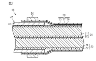
- FIG. 2 is a schematic cross-sectional view showing a wire harness of one embodiment.
- FIG. 3 is a schematic cross-sectional view showing a wire harness of one embodiment.
- FIG. 4 is a schematic perspective view showing a wire harness of one embodiment.
- FIG. 5 is a schematic cross-sectional view showing a wire harness of a modified example.
- the wire harness of the present disclosure includes an electric wire, a metal tubular member in which the electric wire is housed, and an electromagnetic shield member that surrounds the outer periphery of the electric wire drawn from the tubular member.
- the electromagnetic shield member has a sheet-shaped metal layer that is electrically connected to the tubular member, and the metal layer is formed of the same type of metal as the tubular member.
- the sheet-shaped metal layer of the electromagnetic shield member is formed of the same type of metal as the tubular member. Therefore, even when water adheres to the connecting portion between the metal layer and the cylindrical member, it is possible to suppress the occurrence of electrolytic corrosion on the electromagnetic shield member and the tubular member. As a result, it is possible to suppress a decrease in the reliability of the electrical connection between the electromagnetic shield member and the tubular member.
- the same kind of metal means a metal having substantially the same ionization tendency.
- the fact that the ionization tendencies are substantially the same includes not only cases where the ionization tendencies are the same, but also cases where the ionization tendencies can be regarded as substantially the same even if they are different because the ionization tendencies are close to each other.
- the metal layer has an inner peripheral surface facing the electric wire and an outer peripheral surface opposite to the inner peripheral surface, and the electromagnetic shield member is formed on the outer peripheral surface of the metal layer. It preferably has one resin layer, and the first resin layer has a higher radiance rate than the metal layer. According to this configuration, even when the emissivity of the metal layer is low, the outer peripheral surface of the metal layer is covered with the first resin layer having a high emissivity. Therefore, the heat radiation due to radiation can be increased as compared with the case where the first resin layer is not provided. Thereby, the heat dissipation property of the electromagnetic shield member can be improved. As a result, the heat dissipation of the wire harness can be improved.
- the electromagnetic shield member has a second resin layer formed on the inner peripheral surface of the metal layer, and the second resin layer has a higher emissivity than the metal layer. According to this configuration, even when the emissivity of the metal layer is low, the inner peripheral surface of the metal layer is covered with the second resin layer having a high emissivity. Therefore, the heat radiation due to radiation can be increased as compared with the case where the second resin layer is not provided. As a result, the heat dissipation of the electromagnetic shield member can be improved, and the heat dissipation of the wire harness can be improved.
- the first resin layer has a Young's modulus lower than that of the metal layer
- the second resin layer has a Young's modulus lower than that of the metal layer.
- a first resin layer and a second resin layer having a Young's modulus lower than that of the metal layer are formed on the inner peripheral surface and the outer peripheral surface of the metal layer, respectively. Therefore, the flexibility and extensibility of the electromagnetic shield member can be improved as compared with the single-layer structure having only a metal layer. As a result, for example, in the bent portion of the electric wire, the electromagnetic shield member can easily follow the bent shape, and it is possible to prevent the metal layer from being broken.
- the electromagnetic shield member has a connecting portion connected to the outer peripheral surface of the tubular member, and the inner peripheral surface of the metal layer in the connecting portion is exposed from the second resin layer. , It is preferable that the tubular member is in direct contact with the outer peripheral surface. According to this configuration, at the connecting portion of the electromagnetic shield member connected to the outer peripheral surface of the tubular member, the inner peripheral surface of the metal layer exposed from the second resin layer is directly in contact with the outer peripheral surface of the tubular member. ing. Therefore, even when the second resin layer is formed on the inner peripheral surface of the metal layer, the metal layer and the tubular member can be suitably electrically connected.
- the electromagnetic shield member is formed in a cylindrical shape that surrounds the outer circumference of the tubular member, and the fixing member is a caulking ring that tightens the electromagnetic shield member from the outside toward the tubular member. Is preferable. According to this configuration, the electromagnetic shield member is fixed to the cylindrical member by being tightened from the outside toward the tubular member by caulking. As a result, the electrical continuity between the electromagnetic shield member and the cylindrical member can be stably maintained.
- the fixing member is preferably formed of the metal layer and the same type of metal as the tubular member.
- the metal layer of the electromagnetic shield member, the tubular member, and the fixing member are all formed of the same type of metal. Therefore, even when water adheres to the connecting portion between the metal layer and the tubular member and the connecting portion between the electromagnetic shield member and the fixing member, it is possible to suppress the occurrence of electrolytic corrosion between the members.
- the structure of the connecting portion between the metal layer and the tubular member can be made into a non-waterproof structure in which a rubber waterproof cover or the like covering the connecting portion is not provided.
- the electromagnetic shield member is formed in a sheet shape having an end face extending along the length direction of the electric wire, and the electromagnetic shield member is a first direction intersecting the length direction of the electric wire.
- the electromagnetic shield member has one end portion, the first end portion, and a second end portion provided on the opposite side in the first direction, and the electromagnetic shield member has the second end portion at the first end portion.
- the wires are formed in a tubular shape that surrounds the outer circumference of the electric wire over the entire circumference in the circumferential direction. According to this configuration, by superimposing the second end portion on the first end portion of the sheet-shaped electromagnetic shield member, the electromagnetic shield member forms a cylindrical shape that surrounds the outer circumference of the electric wire over the entire circumference in the circumferential direction. It is formed. Therefore, the electromagnetic shield member can be easily attached to the electric wire later. Thereby, the assembly workability of the wire harness can be improved.
- the wire harness 10 shown in FIG. 1 electrically connects two or three or more electric devices 11 and 12.
- the electric devices 11 and 12 are installed in a vehicle V such as a hybrid vehicle or an electric vehicle.
- Examples of the electric devices 11 and 12 include a battery, an inverter, a motor, an air conditioner device, a winker device, an airbag device, and the like.
- the wire harness 10 includes one or a plurality of electric wires (two in the present embodiment), an electromagnetic shield member 30 that electromagnetically shields the plurality of electric wires 20, and the electric wires 20. It has a pair of connectors 40 attached to both ends. As shown in FIG. 2, the connector 40 has a metal tubular member 41.
- each electric wire 20 is connected to the electric device 11 via one connector 40, and the other end of each electric wire 20 is connected to the electric device 12 via the other connector 40.
- Each electric wire 20 is formed by being bent into a two-dimensional shape or a three-dimensional shape, for example.
- each electric wire 20 has a conductive core wire 21 and an insulating coating 22 that covers the outer periphery of the core wire 21.
- Each electric wire 20 is a non-shielded electric wire that does not have a shield structure by itself.
- Each electric wire 20 is, for example, a high-voltage electric wire capable of dealing with a high voltage and a large current.
- the core wire 21 is formed in a long shape.
- Examples of the core wire 21 include a stranded wire made by twisting a plurality of metal strands, a columnar conductor made of one columnar metal rod having a solid structure inside, and a tubular conductor having a hollow structure inside. Can be used. Further, as the core wire 21, a stranded wire, a columnar conductor or a cylindrical conductor may be used in combination.
- a metal material such as pure copper, copper alloy, pure aluminum, or aluminum alloy can be used.
- the cross-sectional shape of the core wire 21, that is, the cross-sectional shape of the core wire 21 cut by a plane orthogonal to the length direction of the core wire 21 can be any shape.
- the cross-sectional shape of the core wire 21 is formed, for example, in a circular shape.
- the insulating coating 22 surrounds the outer peripheral surface of each core wire 21 over the entire circumference in the circumferential direction, for example.
- the outer peripheral surface of the insulating coating 22 is formed, for example, in a shape corresponding to the outer peripheral surface of the core wire 21.
- the insulating coating 22 of the present embodiment is formed in a cylindrical shape having a circular inner and outer peripheral cross-sectional shapes.
- the insulating coating 22 is made of an insulating material such as a synthetic resin.
- the insulating coating 22 can be formed, for example, by extrusion molding (extrusion coating) on the core wire 21.
- each electric wire 20 in the length direction is inserted into the tubular member 41 of the connector 40. That is, the end portion of each electric wire 20 in the length direction is housed inside the tubular member 41. Of the electric wire 20 and the electromagnetic shield member 30, only the electric wire 20 is inserted inside the tubular member 41. Then, each electric wire 20 is pulled out from the tubular member 41.
- the electromagnetic shield member 30 is formed in a long cylindrical shape as a whole.
- the electromagnetic shield member 30 is formed so as to surround the outer circumference of the electric wire 20 drawn from the tubular member 41.
- the electromagnetic shield member 30 is formed so as to surround the outer periphery of the plurality of electric wires 20 over the entire circumference in the circumferential direction, for example.
- the electromagnetic shield member 30 is formed in the form of a flexible sheet.
- the electromagnetic shield member 30 is formed in the form of a long sheet extending along the length direction of the electric wire 20, for example.
- the electromagnetic shield member 30 has, for example, an end face 31 extending along the length direction of the electric wire 20.
- the electromagnetic shield member 30 has a width extending in the first direction intersecting the length direction of the electric wire 20.
- the electromagnetic shield member 30 is formed so as to form a cylinder by, for example, winding a flexible sheet material in the circumferential direction of the electric wire 20.
- the electromagnetic shield member 30 includes, for example, an end portion 32 in the first direction intersecting the length direction of the electric wire 20, that is, the width direction of the electromagnetic shield member 30, and an end portion 33 opposite to the end portion 32 in the first direction. have.
- the electromagnetic shield member 30 is formed so as to form a cylinder by, for example, superimposing the end portion 32 and the end portion 33 in the radial direction of the electric wire 20.
- the electromagnetic shield member 30 is formed in a cylindrical shape by superimposing the end portion 33 on the outer peripheral surface of the end portion 32.
- the inner peripheral dimension of the electromagnetic shield member 30 can be adjusted to match the outer peripheral dimension of the plurality of electric wires 20 by adjusting the overlapping width of the end portion 32 and the end portion 33, for example.
- the electromagnetic shield member 30 has elasticity capable of returning from, for example, a tubular state capable of surrounding the outer circumferences of the plurality of electric wires 20 to a sheet state not surrounding the outer circumferences of the plurality of electric wires 20.
- the electromagnetic shield member 30 has, for example, a metal layer 35, a resin layer 36, and an adhesive layer 37 for adhering the metal layer 35 and the resin layer 36. That is, the electromagnetic shield member 30 has a laminated structure in which the metal layer 35, the adhesive layer 37, and the resin layer 36 are laminated in this order.
- the electromagnetic shield member 30 is arranged so that, for example, the metal layer 35 faces the electric wire 20. That is, the electromagnetic shield member 30 is formed so that the metal layer 35 is arranged inside the electromagnetic shield member 30 having a cylindrical shape in the radial direction. In other words, the electromagnetic shield member 30 is formed so that the resin layer 36 is arranged on the radial outer side of the cylindrical electromagnetic shield member 30.
- each member constituting the electromagnetic shield member 30 facing the electric wire 20 side is referred to as an "inner peripheral surface”, and the end surface opposite to the inner peripheral surface is referred to as an “outer peripheral surface”. ..
- the metal layer 35 is formed in a sheet shape.
- the metal layer 35 has an electromagnetic shielding function.
- a sheet material made of a metal foil or a metal material can be used.
- a metal material such as pure copper, a copper alloy, pure aluminum, or an aluminum alloy can be used.
- the metal layer 35 of the present embodiment is a metal foil made of pure aluminum.
- the adhesive layer 37 is adhered to the metal layer 35 and also to the resin layer 36.
- the adhesive layer 37 is adhered to the outer peripheral surface of the metal layer 35 and also to the inner peripheral surface of the resin layer 36.
- the adhesive layer 37 is formed so as to cover the outer peripheral surface of the metal layer 35.
- the adhesive layer 37 is formed so as to cover the entire outer peripheral surface of the metal layer 35, for example.
- an epoxy resin-based, polyurethane-based, or acrylic resin-based adhesive can be used.
- a conductive adhesive having conductivity can be used as the adhesive layer 37.
- the resin layer 36 is formed in a sheet shape.
- the resin layer 36 is formed so as to cover the outer peripheral surface of the adhesive layer 37.
- the resin layer 36 is formed so as to cover the entire outer peripheral surface of the adhesive layer 37, for example.
- the size of the resin layer 36 is formed according to, for example, the size of the metal layer 35.
- a resin material having a higher emissivity than the metal layer 35 can be used.
- the emissivity of the resin layer 36 can be set to 0.7 or more, for example.
- a resin material having a Young's modulus lower than that of the metal layer 35 can be used as the material of the resin layer 36.
- a resin material having conductivity or a resin material having no conductivity can be used.
- a synthetic resin such as polypropylene (PP), polyethylene terephthalate (PET), or polyethylene (PE) can be used.
- the metal (for example, aluminum) constituting the metal layer 35 is generally excellent in terms of thermal conductivity, but is often not excellent in terms of emissivity (emissivity).
- emissivity for example, the emissivity of aluminum is 0.1 or less. Therefore, the resin layer 36 having a higher emissivity than the outer peripheral surface of the metal layer 35 is adhered to the outer peripheral surface of the metal layer 35. As a result, the heat radiation due to radiation can be increased as compared with the case where the resin layer 36 is not formed.
- the peak wavelength of light emitted from an object by heat radiation is inversely proportional to the temperature of the object. Further, it is known that there are materials that take different values of emissivity depending on the temperature (wavelength of light) of an object even if the materials are the same.
- the resin layer 36 since the wire harness 10 is mounted on the vehicle V (see FIG. 1), the resin layer 36 has a high emissivity with respect to the peak wavelength in the high temperature zone generated in the usage environment of the vehicle. Is preferable.
- the inner peripheral surface of the metal layer 35 at the end 33 is in contact with the outer peripheral surface of the resin layer 36 at the end 32.
- the metal layer 35 at the end portion 32 and the metal layer 35 at the end portion 33 are arranged so as to overlap each other in the radial direction of the electric wire 20, so that the metal layer 35 is doubly overlapped. It is rolled up.
- the electromagnetic shield member 30 of this embodiment does not have an adhesive surface or an adhesive surface. Specifically, the electromagnetic shield member 30 of the present embodiment does not have an adhesive surface or an adhesive surface formed on the inner peripheral surface of the metal layer 35 and the outer peripheral surface of the resin layer 36.
- the electromagnetic shield member 30 is maintained in a tubular state by, for example, winding a binding member (not shown). As the binding member, for example, a tape member or a binding band can be used.
- the binding members are provided, for example, at predetermined intervals in the length direction of the electromagnetic shield member 30.
- the end portion of the electromagnetic shield member 30 in the length direction is connected to the outer peripheral surface of the tubular member 41. That is, the end portion of the electromagnetic shield member 30 in the length direction is a connecting portion connected to the tubular member 41.
- the inner peripheral surface of the metal layer 35 is in contact with the outer peripheral surface of the tubular member 41.
- the electromagnetic shield member 30 is electrically connected to the tubular member 41.
- the electromagnetic shield member 30 is grounded (grounded) to the vehicle body panel or the like through the tubular member 41.
- the wire harness 10 has, for example, a caulking ring 50 that fixes the electromagnetic shield member 30 to the cylindrical member 41 in a state where the metal layer 35 is in contact with the cylindrical member 41.
- the caulking ring 50 is attached to the outer peripheral surface of the tubular member 41.
- the caulking ring 50 has a tubular shape along the outer peripheral surface of the tubular member 41.
- the tubular member 41 is formed in a cylindrical shape
- the caulking ring 50 is formed in a cylindrical shape along the outer peripheral surface of the tubular member 41.
- the caulking ring 50 is fitted to the outside of the tubular member 41 in such a manner that the end portion of the electromagnetic shield member 30 in the length direction is sandwiched between the caulking ring 50 and the outer peripheral surface of the tubular member 41. Then, by tightening the caulking ring 50 inward in the radial direction of the tubular member 41, the end portion of the electromagnetic shield member 30 in the length direction is fixed in direct contact with the outer peripheral surface of the tubular member 41. There is. That is, the end portion of the electromagnetic shield member 30 in the length direction faces the cylindrical member 41 from the outside by the caulking 50 in a state where the inner peripheral surface of the metal layer 35 is in direct contact with the outer peripheral surface of the tubular member 41.
- the caulking ring 50 maintains the tubular state of the electromagnetic shield member 30.
- the inner peripheral surface of the caulking ring 50 is in contact with the outer peripheral surface of the resin layer 36.
- the material of the tubular member 41 for example, an iron-based, aluminum-based or copper-based metal material can be used.
- the tubular member 41 may be subjected to surface treatment such as tin plating or aluminum plating depending on the type of the constituent metal and the usage environment. That is, the tubular member 41 may have a structure in which a plating film is formed on the surface of the base material.
- the material of the caulking ring 50 for example, an iron-based, aluminum-based or copper-based metal material can be used.
- the caulking ring 50 may be subjected to surface treatment such as tin plating or aluminum plating depending on the type of the constituent metal and the usage environment. That is, the caulking ring 50 may have a structure in which a plating film is formed on the surface of the base material.
- the metal layer 35 of the electromagnetic shield member 30 is formed of the same type of metal as the tubular member 41.
- the same type of metal refers to a metal having substantially the same ionization tendency. The fact that the ionization tendencies are substantially the same includes not only cases where the ionization tendencies are the same, but also cases where the ionization tendencies can be regarded as substantially the same even if they are different because the ionization tendencies are close to each other.
- the range in which the ionization tendency of the first metal and the second metal can be regarded as substantially the same is a combination of metals that do not cause electrolytic corrosion when the first metal and the second metal are electrically connected by an aqueous solution containing an electrolyte. In addition to the above, it also includes a combination of metals that can be used in vehicles and the like without any problem in practical use even if electrolytic corrosion occurs.
- the metal layer 35 is formed of the same type of metal as the outermost surface of the tubular member 41. For example, when the tubular member 41 has a structure in which a plating film is formed on the surface of the base material, the plating film and the metal layer 35 are formed of the same type of metal.
- the caulking ring 50 of the present embodiment is formed of the same type of metal as the metal layer 35 and the tubular member 41.
- the caulking ring 50 has a structure in which a plating film is formed on the surface of the base material, the plating film is formed of the same type of metal as the metal layer 35.
- the metal layer 35 is made of pure aluminum or an aluminum alloy
- the tubular member 41 is made of an aluminum alloy
- the caulking ring 50 is made of an aluminum alloy.
- a 1000-series or 8000-series aluminum alloy containing pure aluminum can be preferably used.
- a 3000 series aluminum alloy or an aluminum alloy for die casting (ADC material) can be used as the material of the tubular member 41.
- the ADC material include an aluminum alloy ADC3 and an aluminum alloy ADC12.
- tubular member 41 a structure in which a base material made of an iron alloy is plated with molten aluminum to form an aluminum plating film on the surface of the base material can also be used.
- the iron alloy for example, carbon steel, special steel or stainless steel can be used.
- the caulking 50 of the present embodiment has a structure in which an aluminum-plated film is formed on the surface of the base material by subjecting the base material made of an iron alloy to hot-dip aluminum plating.
- the wire harness 10 has, for example, an exterior member 60 that surrounds the outer periphery of the electromagnetic shield member 30.
- the exterior member 60 has a long cylindrical shape as a whole.
- the exterior member 60 is formed so as to surround the outer periphery of the electromagnetic shield member 30 over the entire circumference in the circumferential direction, for example.
- an electromagnetic shield member 30 and a plurality of electric wires 20 covered with the electromagnetic shield member 30 are housed.
- the exterior member 60 protects the electric wire 20 and the electromagnetic shield member 30 housed therein from flying objects and water droplets. In FIG. 2, the exterior member 60 is not shown.
- a metal or resin pipe, a corrugated tube, a rubber waterproof cover, or a combination thereof can be used as the exterior member 60.
- a metal or resin pipe, a corrugated tube, a rubber waterproof cover, or a combination thereof can be used as the exterior member 60.
- a metal material such as aluminum-based or copper-based can be used.
- a resin material having conductivity or a resin material having no conductivity can be used as the resin material.
- synthetic resins such as polyolefin, polyamide, polyester, and ABS resin can be used.
- the metal layer 35 of the electromagnetic shield member 30 is formed of the same type of metal as the tubular member 41.
- the metal layer 35 and the tubular member 41 are all formed of an aluminum-based metal material. Therefore, even when water adheres to the connecting portion between the metal layer 35 and the tubular member 41, it is possible to suitably suppress the occurrence of electrolytic corrosion. As a result, it is possible to prevent the electromagnetic shielding performance of the electromagnetic shielding member 30 from deteriorating due to electrolytic corrosion.
- the structure of the connecting portion between the metal layer 35 and the tubular member 41 may be a non-waterproof structure in which a rubber waterproof cover or the like covering the connecting portion is not provided.
- a resin layer 36 having a higher emissivity than the metal layer 35 is formed on the outer peripheral surface of the metal layer 35. According to this configuration, even when the emissivity of the metal layer 35 is low, the outer peripheral surface of the metal layer 35 is covered with the resin layer 36 having a high emissivity. Therefore, the heat radiation due to radiation can be increased as compared with the case where the resin layer 36 is not provided. Therefore, for example, even if the outer peripheral surface of the electromagnetic shield member 30 and the inner peripheral surface of the exterior member 60 are physically separated, heat can be efficiently conducted to the exterior member 60 by radiation from the outer peripheral surface of the electromagnetic shield member 30. can. As a result, the heat dissipation of the electromagnetic shield member 30 can be improved, and the heat dissipation of the wire harness 10 can be improved.
- a resin layer 36 having a Young's modulus lower than that of the metal layer 35 is formed on the outer peripheral surface of the metal layer 35. According to this configuration, the flexibility and extensibility of the electromagnetic shield member 30 can be enhanced as compared with the single-layer structure having only the metal layer 35. As a result, for example, in the bent portion of the electric wire 20, the electromagnetic shield member 30 can easily follow the bent shape, and the metal layer 35 can be prevented from being broken.
- the resin layer 36 is formed only on the outer peripheral surface of the inner peripheral surface and the outer peripheral surface of the metal layer 35. That is, the resin layer was not formed on the inner peripheral surface of the metal layer 35. Therefore, when the end portion of the electromagnetic shield member 30 in the length direction is fixed to the tubular member 41, the inner peripheral surface of the metal layer 35 can be brought into direct contact with the outer peripheral surface of the tubular member 41. As a result, the electromagnetic shield member 30 and the tubular member 41 are preferably used at the end portion of the electromagnetic shield member 30 in the length direction, that is, at the connection portion with the tubular member 41, without performing steps such as peeling the resin layer. Can be electrically connected to.
- the resin layer 36 has an electromagnetic shielding function. Can be maintained.
- a caulking ring 50 for fixing the electromagnetic shield member 30 to the cylindrical member 41 is provided in a state where the metal layer 35 is in contact with the tubular member 41. According to this configuration, the electromagnetic shield member 30 is tightened from the outside toward the cylindrical member 41 by the caulking ring 50, so that the inner peripheral surface of the metal layer 35 is in contact with the outer peripheral surface of the cylindrical member 41. The shield member 30 is fixed to the tubular member 41. As a result, the electrical continuity between the electromagnetic shield member 30 and the cylindrical member 41 can be stably maintained.
- the caulking ring 50 is formed of the same type of metal as the metal layer 35 of the electromagnetic shield member 30 and the tubular member 41. According to this configuration, the metal layer 35, the tubular member 41, and the caulking ring 50 are all formed of the same type of metal. Therefore, even when water adheres to the connecting portion between the metal layer 35 and the tubular member 41 and the connecting portion between the electromagnetic shield member 30 and the caulking ring 50, electrolytic corrosion occurs between the members. Can be suppressed. For example, even when the metal layer 35 and the caulking ring 50 are electrically connected via water, it is possible to suppress the occurrence of electrolytic corrosion between the metal layer 35 and the caulking ring 50. As a result, the structure of the connecting portion between the metal layer 35 and the tubular member 41 can be made into a non-waterproof structure in which a rubber waterproof cover or the like covering the connecting portion is not provided.
- the electromagnetic shield member 30 is formed in a cylindrical shape that surrounds the outer circumference of the electric wire 20 over the entire circumference in the circumferential direction. .. Therefore, the electromagnetic shield member 30 can be easily attached to the electric wire 20 later. Thereby, the assembling workability of the wire harness 10 can be improved.
- the inner peripheral dimension and the outer peripheral dimension of the electromagnetic shield member 30 can be easily adjusted according to the outer peripheral dimension of the electric wire 20. As a result, it is possible to preferably suppress an increase in the outer peripheral dimension of the electromagnetic shield member 30.
- the resin layer 36 is formed only on the outer peripheral surface of the inner peripheral surface and the outer peripheral surface of the metal layer 35, but the present invention is not limited to this.
- the resin layer 36 may be formed on the outer peripheral surface of the metal layer 35, and the resin layer 38 may be formed on the inner peripheral surface of the metal layer 35.
- the resin layer 38 is adhered to the inner peripheral surface of the metal layer 35 via the adhesive layer 39. That is, the electromagnetic shield member 30A has a laminated structure in which the resin layer 38, the adhesive layer 39, the metal layer 35, the adhesive layer 37, and the resin layer 36 are sequentially laminated from the inner peripheral surface side of the electromagnetic shield member 30. ..
- the electromagnetic shield member 30A is arranged so that, for example, the resin layer 38 faces the electric wire 20.
- the adhesive layer 39 is adhered to the inner peripheral surface of the metal layer 35 and also to the outer peripheral surface of the resin layer 38.
- the adhesive layer 39 is formed so as to cover the inner peripheral surface of the metal layer 35.
- an epoxy resin-based, polyurethane-based, or acrylic resin-based adhesive can be used as the adhesive layer 39.
- the resin layer 38 is formed in a sheet shape.
- the resin layer 38 is formed so as to cover the outer peripheral surface of the adhesive layer 39.
- the resin layer 38 is formed so as to cover the entire outer peripheral surface of the adhesive layer 39, for example.
- a resin material having a higher emissivity than the metal layer 35 can be used.
- the emissivity of the resin layer 38 can be set to 0.7 or more, for example.
- a resin material having a Young's modulus lower than that of the metal layer 35 can be used.
- a resin material having conductivity or a resin material having no conductivity can be used.
- a synthetic resin such as polypropylene, polyethylene terephthalate or polyethylene can be used.
- the end portion of the electromagnetic shield member 30A in the length direction is connected to the outer peripheral surface of the tubular member 41. That is, the end portion of the electromagnetic shield member 30A in the length direction is a connecting portion connected to the tubular member 41.
- the inner peripheral surface of the metal layer 35 is exposed from the resin layer 38, and the inner peripheral surface of the metal layer 35 is in direct contact with the outer peripheral surface of the tubular member 41.
- the adhesive layer 39 and the resin layer 38 are not formed on the inner peripheral surface of the metal layer 35 at the connecting portion of the electromagnetic shield member 30A. Therefore, at the connecting portion of the electromagnetic shield member 30A, the inner peripheral surface of the metal layer 35 can be brought into direct contact with the outer peripheral surface of the tubular member 41. As a result, even when the resin layer 38 is formed on the inner peripheral surface of the metal layer 35, the metal layer 35 and the tubular member 41 can be suitably electrically connected.
- the inner peripheral surface of the metal layer 35 is covered with the resin layer 38 having a high emissivity. Therefore, the heat radiation due to radiation can be increased as compared with the case where the resin layer 38 is not provided. Therefore, for example, even if the inner peripheral surface of the electromagnetic shield member 30, here, the inner peripheral surface of the resin layer 38 and the outer peripheral surface of the electric wire 20 are physically separated, the electromagnetic shield member 30 is radiated from the outer peripheral surface of the electric wire 20. Heat can be efficiently conducted.
- the outer peripheral surface of the metal layer 35 is covered with the resin layer 36 having a high emissivity, it is possible to efficiently conduct heat from the outer peripheral surface of the electromagnetic shield member 30 to the exterior member 60 (see FIG. 3) by radiation. can. Thereby, the heat dissipation property of the wire harness 10 can be improved. As a result, the temperature rise of the electric wire 20 can be suppressed to a low level, so that the size of the core wire 21 of the electric wire 20 can be reduced and the thickness of the insulating coating 22 can be reduced.
- the flexibility and extensibility of the electromagnetic shield member 30A can be improved as compared with the case where the resin layer 38 is not provided. Can be enhanced. As a result, for example, in the bent portion of the electric wire 20, the electromagnetic shield member 30A can easily follow the bent shape, and the metal layer 35 can be further suppressed from being broken.
- the adhesive layer 37 and the resin layer 36 may be omitted from the electromagnetic shield member 30A shown in FIG.
- the electromagnetic shield member 30A in this case is composed of a metal layer 35 and a resin layer 38 bonded to the inner peripheral surface of the metal layer 35 by an adhesive layer 39.
- the adhesive layer 37 and the resin layer 36 may be omitted from the electromagnetic shield member 30 of the above embodiment.
- the electromagnetic shield member 30 in this case is composed of only the metal layer 35.
- the resin layer 36 is adhered to the outer peripheral surface of the metal layer 35 by the adhesive layer 37, but the present invention is not limited to this.
- the resin layer 36 may be formed on the outer peripheral surface of the metal layer 35 by a coating treatment in which a paint having a higher emissivity than the metal layer 35 is applied.
- the adhesive layer 37 is omitted.
- the resin layer 38 is adhered to the inner peripheral surface of the metal layer 35 by the adhesive layer 39, but the present invention is not limited to this.
- the resin layer 38 may be formed by a coating treatment in which a paint having a higher emissivity than the metal layer 35 is applied to the inner peripheral surface of the metal layer 35.
- the adhesive layer 39 is omitted.
- the adhesive layer or the adhesive layer may be provided on one surface of the electromagnetic shield member 30 of the above embodiment.
- an adhesive layer or an adhesive layer may be provided on the outer peripheral surface of the end portion 32 of the electromagnetic shield member 30.
- the electromagnetic shield member 30 is formed into a cylindrical shape by superimposing the ends 32 and 33 in the width direction of the electromagnetic shield member 30 on each other.
- the electromagnetic shield member 30 may be formed into a cylindrical shape by overlapping the intermediate portions of the electromagnetic shield member 30 in the width direction.
- the widthwise ends 32 and 33 of the electromagnetic shield member 30 do not have to overlap each other. That is, the inner peripheral surface of the end portion 33 does not have to be in contact with the outer peripheral surface of the end portion 32.
- the electromagnetic shield member 30 may be wound around the electric wire 20 so as to be doubly overlapped over the entire circumference of the electromagnetic shield member 30 in the circumferential direction.
- the inner peripheral surface and the outer peripheral surface of the electromagnetic shield member 30 in the sheet state before being wound into a cylindrical shape are formed to be flat, but the present invention is not limited to this.
- a plurality of slits may be formed on the inner peripheral surface and the outer peripheral surface of the electromagnetic shield member 30.
- the plurality of slits may be formed so as to make the electromagnetic shield member 30 easy to bend. For example, when a plurality of slits formed on the inner peripheral surface and the outer peripheral surface of the electromagnetic shield member 30 extend in the length direction of the electric wire 20, when the electromagnetic shield member 30 is wound around the outer peripheral surface of the electric wire 20, the electromagnetic shield member 30 is wound.
- the electromagnetic shield member 30 easily bends and deforms following the outer peripheral surface of the electric wire 20.
- the plurality of slits are advantageous in reducing the occurrence of bending wrinkles in the metal layer 35 of the electromagnetic shield member 30 due to bending deformation of the electromagnetic shield member 30, for example.
- the caulking ring 50 is embodied in a structure in which an aluminum-plated film is formed on the surface of a base material made of an iron alloy, but the present invention is not limited to this.
- the base material of the caulking ring 50 may be made of an aluminum alloy.
- the caulking ring 50 in this case can be formed as follows, for example. First, a cylindrical aluminum alloy pipe having an inner diameter larger than the outer diameter of the tubular member 41 is arranged outside the electromagnetic shield member 30 provided so as to surround the outer circumference of the tubular member 41. That is, the aluminum alloy pipe is arranged outside the electromagnetic shield member 30 so as to overlap the cylindrical member 41 and the electromagnetic shield member 30 in the radial direction.
- the aluminum alloy pipe is pressed inward in the radial direction over substantially the entire circumference in the circumferential direction.
- the aluminum alloy pipe is plastically deformed so as to be reduced in diameter to form the caulking ring 50.
- the metal layer 35, the tubular member 41, and the caulking ring 50 of the above embodiment may all be made of a copper-based metal material. Further, the metal layer 35, the tubular member 41, and the caulking ring 50 may all be made of a tin-based metal material.
- the caulking ring 50 is made of the same type of metal as the metal layer 35 and the tubular member 41. Not limited to this, for example, the caulking ring 50 may be made of a metal layer 35, a tubular member 41, and a different kind of metal.
- the caulking ring 50 is used as a fixing member for fixing the end portion of the electromagnetic shield member 30 to the outer peripheral surface of the tubular member 41 in a state of being electrically connected, but the present invention is not limited to this.
- a metal band, a resin binding band, an adhesive tape, or the like may be used as the fixing member.
- the tubular member to which the electromagnetic shield member 30 is connected is embodied in the tubular member 41 included in the connector 40, but the present invention is not limited to this.
- the tubular member to which the electromagnetic shield member 30 is connected may be embodied in a metal pipe constituting the exterior member 60.
- the connecting portion between the electromagnetic shield member 30 and the tubular member is arranged at the intermediate portion in the length direction of the wire harness 10.
- the electromagnetic shield member 30 is provided inside the exterior member 60, but the present invention is not limited to this.
- the electromagnetic shield member 30 may be provided on the outside of the exterior member 60.
- the electromagnetic shield member 30 in this case is provided so as to surround the outer periphery of the exterior member 60.
- the exterior member 60 may be omitted from the wire harness 10 of the above embodiment.
- the number of electric wires 20 constituting the wire harness 10 is two, but the present invention is not limited to this.
- the number of electric wires 20 can be changed according to the specifications of the vehicle V.
- the number of electric wires 20 may be one or three or more.
- a low-voltage electric wire for connecting the low-voltage battery and various low-voltage devices for example, a lamp, a car audio, etc.
- the electromagnetic shield member 30 is formed in a long cylindrical shape, and the end portion of the electromagnetic shield member 30 in the length direction is provided so as to cover the outer periphery of the tubular member 41.
- the metal layer 35 arranged radially inside the electromagnetic shield member 30 may be in direct contact with the cylindrical member 41 without the intervention of any other member, and the metal layer 35 and the tubular member 41 may be brought into direct contact with each other. It is not necessary to provide a waterproof member that seals the contact portion in a watertight state.
- the metal tubular member 41 of each connector 40 may be the shield shell of the connector 40 connected to the ground.
- the metal layer 35 of the electromagnetic shield member 30 may extend seamlessly between the two connectors 40 at both ends of the electric wire 20, and may electrically connect the metal tubular member 41 of the two connectors 40.
- the metal layer 35 of the cylindrical electromagnetic shield member 30 shown in FIGS. 3 and 4 may be referred to as a metal foil roll extending over the entire length of the electromagnetic shield member 30.
Landscapes
- Engineering & Computer Science (AREA)
- Mechanical Engineering (AREA)
- Architecture (AREA)
- Civil Engineering (AREA)
- Structural Engineering (AREA)
- Microelectronics & Electronic Packaging (AREA)
- Shielding Devices Or Components To Electric Or Magnetic Fields (AREA)
- Insulated Conductors (AREA)
- Details Of Indoor Wiring (AREA)
Priority Applications (2)
| Application Number | Priority Date | Filing Date | Title |
|---|---|---|---|
| CN202180089253.9A CN116724363A (zh) | 2021-01-13 | 2021-12-24 | 线束 |
| US18/270,099 US20240317153A1 (en) | 2021-01-13 | 2021-12-24 | Wire harness |
Applications Claiming Priority (2)
| Application Number | Priority Date | Filing Date | Title |
|---|---|---|---|
| JP2021003654A JP7581890B2 (ja) | 2021-01-13 | 2021-01-13 | ワイヤハーネス |
| JP2021-003654 | 2021-01-13 |
Publications (1)
| Publication Number | Publication Date |
|---|---|
| WO2022153850A1 true WO2022153850A1 (ja) | 2022-07-21 |
Family
ID=82447784
Family Applications (1)
| Application Number | Title | Priority Date | Filing Date |
|---|---|---|---|
| PCT/JP2021/048425 Ceased WO2022153850A1 (ja) | 2021-01-13 | 2021-12-24 | ワイヤハーネス |
Country Status (4)
| Country | Link |
|---|---|
| US (1) | US20240317153A1 (https=) |
| JP (1) | JP7581890B2 (https=) |
| CN (1) | CN116724363A (https=) |
| WO (1) | WO2022153850A1 (https=) |
Families Citing this family (1)
| Publication number | Priority date | Publication date | Assignee | Title |
|---|---|---|---|---|
| JP7738817B2 (ja) * | 2022-10-20 | 2025-09-16 | 東南貿易株式会社 | ケーブルおよびケーブルの製造方法 |
Citations (3)
| Publication number | Priority date | Publication date | Assignee | Title |
|---|---|---|---|---|
| JP2011254613A (ja) * | 2010-06-02 | 2011-12-15 | Yazaki Corp | 編組シールド部材、編組シールド部材の製造方法、及びワイヤハーネス |
| JP2016181587A (ja) * | 2015-03-24 | 2016-10-13 | 株式会社オートネットワーク技術研究所 | 電磁シールド部材 |
| JP2020021557A (ja) * | 2018-07-30 | 2020-02-06 | 株式会社オートネットワーク技術研究所 | ワイヤハーネス |
Family Cites Families (15)
| Publication number | Priority date | Publication date | Assignee | Title |
|---|---|---|---|---|
| FR2711850B1 (fr) * | 1993-10-22 | 1995-12-29 | Eurocopter France | Procédé et dispositif pour assurer la continuité électrique de blindages de câbles. |
| JP5655630B2 (ja) * | 2011-02-25 | 2015-01-21 | 株式会社オートネットワーク技術研究所 | シールド導電体 |
| CN103198888B (zh) * | 2012-01-05 | 2016-04-20 | 日立金属株式会社 | 差动信号传输用电缆 |
| JP5994758B2 (ja) * | 2013-09-19 | 2016-09-21 | 日立金属株式会社 | ハーネス |
| JP2015076900A (ja) * | 2013-10-04 | 2015-04-20 | 住友電装株式会社 | シールドパイプ |
| DE102015003061A1 (de) * | 2015-03-10 | 2016-09-15 | Sumitomo Wiring Systems, Ltd. | Abgeschirmte Verkabelung, abschirmendes Glied und Verfahren zum Herstellen einer abgeschirmten Verkabelung |
| JP6582649B2 (ja) * | 2015-07-10 | 2019-10-02 | 株式会社オートネットワーク技術研究所 | シールド構造 |
| US10593502B1 (en) * | 2018-08-21 | 2020-03-17 | Superior Essex International LP | Fusible continuous shields for use in communication cables |
| JP6763346B2 (ja) * | 2017-01-23 | 2020-09-30 | 株式会社オートネットワーク技術研究所 | 電磁シールド部品及びワイヤハーネス |
| JP6816660B2 (ja) * | 2017-06-15 | 2021-01-20 | 株式会社オートネットワーク技術研究所 | 電磁シールド部品、ワイヤハーネス及び電磁シールド部品の製造方法 |
| TWI668708B (zh) * | 2017-07-07 | 2019-08-11 | 加川清二 | 電磁波吸收纜線 |
| JP6784940B2 (ja) * | 2017-07-26 | 2020-11-18 | 住友電装株式会社 | 導電路 |
| JP6772999B2 (ja) * | 2017-10-06 | 2020-10-21 | 株式会社オートネットワーク技術研究所 | シールド接続構造及びワイヤーハーネス |
| JP6922791B2 (ja) * | 2018-03-08 | 2021-08-18 | 株式会社オートネットワーク技術研究所 | 固定部材付き保護管及びワイヤハーネス |
| US20210065934A1 (en) * | 2019-09-04 | 2021-03-04 | Te Connectivity Corporation | Electrical cable |
-
2021
- 2021-01-13 JP JP2021003654A patent/JP7581890B2/ja active Active
- 2021-12-24 US US18/270,099 patent/US20240317153A1/en active Pending
- 2021-12-24 CN CN202180089253.9A patent/CN116724363A/zh active Pending
- 2021-12-24 WO PCT/JP2021/048425 patent/WO2022153850A1/ja not_active Ceased
Patent Citations (3)
| Publication number | Priority date | Publication date | Assignee | Title |
|---|---|---|---|---|
| JP2011254613A (ja) * | 2010-06-02 | 2011-12-15 | Yazaki Corp | 編組シールド部材、編組シールド部材の製造方法、及びワイヤハーネス |
| JP2016181587A (ja) * | 2015-03-24 | 2016-10-13 | 株式会社オートネットワーク技術研究所 | 電磁シールド部材 |
| JP2020021557A (ja) * | 2018-07-30 | 2020-02-06 | 株式会社オートネットワーク技術研究所 | ワイヤハーネス |
Also Published As
| Publication number | Publication date |
|---|---|
| JP2022108578A (ja) | 2022-07-26 |
| CN116724363A (zh) | 2023-09-08 |
| JP7581890B2 (ja) | 2024-11-13 |
| US20240317153A1 (en) | 2024-09-26 |
Similar Documents
| Publication | Publication Date | Title |
|---|---|---|
| US9496071B2 (en) | Shield wire | |
| US9502153B2 (en) | Wire harness with coaxial composite conductive path | |
| US10532706B2 (en) | Conductive wire and wire harness | |
| US9236720B2 (en) | High voltage conductive wire and wire harness | |
| US9550461B2 (en) | Shielded pipe for a vehicle | |
| WO2020026884A1 (ja) | ワイヤハーネス | |
| JP7463859B2 (ja) | ワイヤハーネスユニット | |
| JP7256456B2 (ja) | ワイヤハーネス | |
| US12588177B2 (en) | Wire harness | |
| US10361517B2 (en) | Electromagnetic shielding component and conductive path | |
| JP2022187711A (ja) | ワイヤハーネス | |
| JP7581890B2 (ja) | ワイヤハーネス | |
| JP6448019B2 (ja) | ワイヤハーネス | |
| JP7463860B2 (ja) | ワイヤハーネスユニット | |
| US12555701B2 (en) | Wire harness with exterior sheet and water repellant | |
| JP7497654B2 (ja) | ワイヤハーネス | |
| WO2022244528A1 (ja) | ワイヤハーネス | |
| JP7848929B2 (ja) | ワイヤハーネス | |
| US20200106248A1 (en) | Electromagnetic shield component, wire harness, and method for manufacturing electromagnetic shield component | |
| JP2022179272A (ja) | ワイヤハーネス | |
| JP7567308B2 (ja) | ワイヤハーネス | |
| JP7497656B2 (ja) | ワイヤハーネス | |
| US20250239382A1 (en) | Wire harness | |
| JP2022127335A (ja) | ワイヤハーネス | |
| WO2023181908A1 (ja) | ワイヤハーネス |
Legal Events
| Date | Code | Title | Description |
|---|---|---|---|
| 121 | Ep: the epo has been informed by wipo that ep was designated in this application |
Ref document number: 21919736 Country of ref document: EP Kind code of ref document: A1 |
|
| WWE | Wipo information: entry into national phase |
Ref document number: 18270099 Country of ref document: US |
|
| WWE | Wipo information: entry into national phase |
Ref document number: 202180089253.9 Country of ref document: CN |
|
| NENP | Non-entry into the national phase |
Ref country code: DE |
|
| 122 | Ep: pct application non-entry in european phase |
Ref document number: 21919736 Country of ref document: EP Kind code of ref document: A1 |