WO2022153850A1 - ワイヤハーネス - Google Patents
ワイヤハーネス Download PDFInfo
- Publication number
- WO2022153850A1 WO2022153850A1 PCT/JP2021/048425 JP2021048425W WO2022153850A1 WO 2022153850 A1 WO2022153850 A1 WO 2022153850A1 JP 2021048425 W JP2021048425 W JP 2021048425W WO 2022153850 A1 WO2022153850 A1 WO 2022153850A1
- Authority
- WO
- WIPO (PCT)
- Prior art keywords
- electromagnetic shield
- metal layer
- shield member
- peripheral surface
- tubular member
- Prior art date
Links
- 229910052751 metal Inorganic materials 0.000 claims abstract description 197
- 239000002184 metal Substances 0.000 claims abstract description 197
- 230000002093 peripheral effect Effects 0.000 claims description 125
- 229920005989 resin Polymers 0.000 claims description 103
- 239000011347 resin Substances 0.000 claims description 103
- 239000010410 layer Substances 0.000 description 214
- 239000000463 material Substances 0.000 description 47
- 239000012790 adhesive layer Substances 0.000 description 32
- 229910000838 Al alloy Inorganic materials 0.000 description 17
- 229910052782 aluminium Inorganic materials 0.000 description 17
- XAGFODPZIPBFFR-UHFFFAOYSA-N aluminium Chemical compound [Al] XAGFODPZIPBFFR-UHFFFAOYSA-N 0.000 description 17
- 238000005260 corrosion Methods 0.000 description 13
- 230000007797 corrosion Effects 0.000 description 13
- 230000005855 radiation Effects 0.000 description 13
- 238000007747 plating Methods 0.000 description 12
- 239000011248 coating agent Substances 0.000 description 10
- 238000000576 coating method Methods 0.000 description 10
- 239000007769 metal material Substances 0.000 description 9
- -1 polypropylene Polymers 0.000 description 8
- RYGMFSIKBFXOCR-UHFFFAOYSA-N Copper Chemical compound [Cu] RYGMFSIKBFXOCR-UHFFFAOYSA-N 0.000 description 7
- 239000000853 adhesive Substances 0.000 description 7
- 230000001070 adhesive effect Effects 0.000 description 7
- 229910052802 copper Inorganic materials 0.000 description 7
- 239000010949 copper Substances 0.000 description 7
- 230000017525 heat dissipation Effects 0.000 description 7
- XLYOFNOQVPJJNP-UHFFFAOYSA-N water Substances O XLYOFNOQVPJJNP-UHFFFAOYSA-N 0.000 description 7
- 229910000640 Fe alloy Inorganic materials 0.000 description 4
- XEEYBQQBJWHFJM-UHFFFAOYSA-N Iron Chemical compound [Fe] XEEYBQQBJWHFJM-UHFFFAOYSA-N 0.000 description 4
- 239000004020 conductor Substances 0.000 description 4
- 229920001971 elastomer Polymers 0.000 description 4
- 239000011888 foil Substances 0.000 description 4
- 229920003002 synthetic resin Polymers 0.000 description 4
- 239000000057 synthetic resin Substances 0.000 description 4
- 239000004698 Polyethylene Substances 0.000 description 3
- 239000004743 Polypropylene Substances 0.000 description 3
- ATJFFYVFTNAWJD-UHFFFAOYSA-N Tin Chemical compound [Sn] ATJFFYVFTNAWJD-UHFFFAOYSA-N 0.000 description 3
- 150000002739 metals Chemical class 0.000 description 3
- 229920000573 polyethylene Polymers 0.000 description 3
- 229920000139 polyethylene terephthalate Polymers 0.000 description 3
- 239000005020 polyethylene terephthalate Substances 0.000 description 3
- 229920001155 polypropylene Polymers 0.000 description 3
- 238000004804 winding Methods 0.000 description 3
- 239000004925 Acrylic resin Substances 0.000 description 2
- 229920000178 Acrylic resin Polymers 0.000 description 2
- 229910000881 Cu alloy Inorganic materials 0.000 description 2
- 238000005452 bending Methods 0.000 description 2
- 239000000470 constituent Substances 0.000 description 2
- 239000003822 epoxy resin Substances 0.000 description 2
- 229910052742 iron Inorganic materials 0.000 description 2
- 238000012986 modification Methods 0.000 description 2
- 230000004048 modification Effects 0.000 description 2
- 239000003973 paint Substances 0.000 description 2
- 229920000647 polyepoxide Polymers 0.000 description 2
- 229920002635 polyurethane Polymers 0.000 description 2
- 239000004814 polyurethane Substances 0.000 description 2
- 239000002356 single layer Substances 0.000 description 2
- 238000004381 surface treatment Methods 0.000 description 2
- 229910000975 Carbon steel Inorganic materials 0.000 description 1
- 101100162020 Mesorhizobium japonicum (strain LMG 29417 / CECT 9101 / MAFF 303099) adc3 gene Proteins 0.000 description 1
- 239000004952 Polyamide Substances 0.000 description 1
- 229910000831 Steel Inorganic materials 0.000 description 1
- 229920000122 acrylonitrile butadiene styrene Polymers 0.000 description 1
- 239000002390 adhesive tape Substances 0.000 description 1
- 239000007864 aqueous solution Substances 0.000 description 1
- 239000010962 carbon steel Substances 0.000 description 1
- 230000002542 deteriorative effect Effects 0.000 description 1
- 238000010586 diagram Methods 0.000 description 1
- 238000004512 die casting Methods 0.000 description 1
- 238000006073 displacement reaction Methods 0.000 description 1
- 230000000694 effects Effects 0.000 description 1
- 239000003792 electrolyte Substances 0.000 description 1
- 238000006056 electrooxidation reaction Methods 0.000 description 1
- 238000001125 extrusion Methods 0.000 description 1
- 238000007765 extrusion coating Methods 0.000 description 1
- 239000011810 insulating material Substances 0.000 description 1
- 238000009413 insulation Methods 0.000 description 1
- 238000000034 method Methods 0.000 description 1
- 229920006122 polyamide resin Polymers 0.000 description 1
- 229920001225 polyester resin Polymers 0.000 description 1
- 229920005672 polyolefin resin Polymers 0.000 description 1
- 239000007787 solid Substances 0.000 description 1
- 239000010935 stainless steel Substances 0.000 description 1
- 229910001220 stainless steel Inorganic materials 0.000 description 1
- 239000010959 steel Substances 0.000 description 1
- 230000037303 wrinkles Effects 0.000 description 1
Images


Classifications
-
- H—ELECTRICITY
- H01—ELECTRIC ELEMENTS
- H01B—CABLES; CONDUCTORS; INSULATORS; SELECTION OF MATERIALS FOR THEIR CONDUCTIVE, INSULATING OR DIELECTRIC PROPERTIES
- H01B7/00—Insulated conductors or cables characterised by their form
-
- H—ELECTRICITY
- H02—GENERATION; CONVERSION OR DISTRIBUTION OF ELECTRIC POWER
- H02G—INSTALLATION OF ELECTRIC CABLES OR LINES, OR OF COMBINED OPTICAL AND ELECTRIC CABLES OR LINES
- H02G3/00—Installations of electric cables or lines or protective tubing therefor in or on buildings, equivalent structures or vehicles
- H02G3/02—Details
- H02G3/04—Protective tubing or conduits, e.g. cable ladders or cable troughs
-
- H—ELECTRICITY
- H05—ELECTRIC TECHNIQUES NOT OTHERWISE PROVIDED FOR
- H05K—PRINTED CIRCUITS; CASINGS OR CONSTRUCTIONAL DETAILS OF ELECTRIC APPARATUS; MANUFACTURE OF ASSEMBLAGES OF ELECTRICAL COMPONENTS
- H05K9/00—Screening of apparatus or components against electric or magnetic fields
Definitions
- This disclosure relates to a wire harness.
- a wire harness used for a vehicle such as a hybrid vehicle or an electric vehicle is provided with an electromagnetic shield member that electromagnetically shields a plurality of electric wires at once.
- an electromagnetic shield member one in which a metal foil is wound in a cylindrical shape so as to enclose a plurality of electric wires at once is known (see, for example, Patent Document 1).
- the longitudinal end of the electromagnetic shield member is fixed to a metal shield shell by caulking. As a result, the electromagnetic shield member is grounded through the shield shell.
- An object of the present disclosure is to provide a wire harness capable of suppressing the occurrence of electrolytic corrosion in the electromagnetic shield member.
- the wire harness of the present disclosure includes an electric wire, a metal tubular member in which the electric wire is housed, and an electromagnetic shield member that surrounds the outer periphery of the electric wire drawn from the tubular member.
- the electromagnetic shield member has a sheet-shaped metal layer that is electrically connected to the tubular member, and the metal layer is formed of the same type of metal as the tubular member.
- the wire harness of the present disclosure it is possible to suppress the occurrence of electrolytic corrosion in the electromagnetic shield member.
- FIG. 1 is a schematic configuration diagram showing a wire harness of one embodiment.
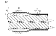
- FIG. 2 is a schematic cross-sectional view showing a wire harness of one embodiment.
- FIG. 3 is a schematic cross-sectional view showing a wire harness of one embodiment.
- FIG. 4 is a schematic perspective view showing a wire harness of one embodiment.
- FIG. 5 is a schematic cross-sectional view showing a wire harness of a modified example.
- the wire harness of the present disclosure includes an electric wire, a metal tubular member in which the electric wire is housed, and an electromagnetic shield member that surrounds the outer periphery of the electric wire drawn from the tubular member.
- the electromagnetic shield member has a sheet-shaped metal layer that is electrically connected to the tubular member, and the metal layer is formed of the same type of metal as the tubular member.
- the sheet-shaped metal layer of the electromagnetic shield member is formed of the same type of metal as the tubular member. Therefore, even when water adheres to the connecting portion between the metal layer and the cylindrical member, it is possible to suppress the occurrence of electrolytic corrosion on the electromagnetic shield member and the tubular member. As a result, it is possible to suppress a decrease in the reliability of the electrical connection between the electromagnetic shield member and the tubular member.
- the same kind of metal means a metal having substantially the same ionization tendency.
- the fact that the ionization tendencies are substantially the same includes not only cases where the ionization tendencies are the same, but also cases where the ionization tendencies can be regarded as substantially the same even if they are different because the ionization tendencies are close to each other.
- the metal layer has an inner peripheral surface facing the electric wire and an outer peripheral surface opposite to the inner peripheral surface, and the electromagnetic shield member is formed on the outer peripheral surface of the metal layer. It preferably has one resin layer, and the first resin layer has a higher radiance rate than the metal layer. According to this configuration, even when the emissivity of the metal layer is low, the outer peripheral surface of the metal layer is covered with the first resin layer having a high emissivity. Therefore, the heat radiation due to radiation can be increased as compared with the case where the first resin layer is not provided. Thereby, the heat dissipation property of the electromagnetic shield member can be improved. As a result, the heat dissipation of the wire harness can be improved.
- the electromagnetic shield member has a second resin layer formed on the inner peripheral surface of the metal layer, and the second resin layer has a higher emissivity than the metal layer. According to this configuration, even when the emissivity of the metal layer is low, the inner peripheral surface of the metal layer is covered with the second resin layer having a high emissivity. Therefore, the heat radiation due to radiation can be increased as compared with the case where the second resin layer is not provided. As a result, the heat dissipation of the electromagnetic shield member can be improved, and the heat dissipation of the wire harness can be improved.
- the first resin layer has a Young's modulus lower than that of the metal layer
- the second resin layer has a Young's modulus lower than that of the metal layer.
- a first resin layer and a second resin layer having a Young's modulus lower than that of the metal layer are formed on the inner peripheral surface and the outer peripheral surface of the metal layer, respectively. Therefore, the flexibility and extensibility of the electromagnetic shield member can be improved as compared with the single-layer structure having only a metal layer. As a result, for example, in the bent portion of the electric wire, the electromagnetic shield member can easily follow the bent shape, and it is possible to prevent the metal layer from being broken.
- the electromagnetic shield member has a connecting portion connected to the outer peripheral surface of the tubular member, and the inner peripheral surface of the metal layer in the connecting portion is exposed from the second resin layer. , It is preferable that the tubular member is in direct contact with the outer peripheral surface. According to this configuration, at the connecting portion of the electromagnetic shield member connected to the outer peripheral surface of the tubular member, the inner peripheral surface of the metal layer exposed from the second resin layer is directly in contact with the outer peripheral surface of the tubular member. ing. Therefore, even when the second resin layer is formed on the inner peripheral surface of the metal layer, the metal layer and the tubular member can be suitably electrically connected.
- the electromagnetic shield member is formed in a cylindrical shape that surrounds the outer circumference of the tubular member, and the fixing member is a caulking ring that tightens the electromagnetic shield member from the outside toward the tubular member. Is preferable. According to this configuration, the electromagnetic shield member is fixed to the cylindrical member by being tightened from the outside toward the tubular member by caulking. As a result, the electrical continuity between the electromagnetic shield member and the cylindrical member can be stably maintained.
- the fixing member is preferably formed of the metal layer and the same type of metal as the tubular member.
- the metal layer of the electromagnetic shield member, the tubular member, and the fixing member are all formed of the same type of metal. Therefore, even when water adheres to the connecting portion between the metal layer and the tubular member and the connecting portion between the electromagnetic shield member and the fixing member, it is possible to suppress the occurrence of electrolytic corrosion between the members.
- the structure of the connecting portion between the metal layer and the tubular member can be made into a non-waterproof structure in which a rubber waterproof cover or the like covering the connecting portion is not provided.
- the electromagnetic shield member is formed in a sheet shape having an end face extending along the length direction of the electric wire, and the electromagnetic shield member is a first direction intersecting the length direction of the electric wire.
- the electromagnetic shield member has one end portion, the first end portion, and a second end portion provided on the opposite side in the first direction, and the electromagnetic shield member has the second end portion at the first end portion.
- the wires are formed in a tubular shape that surrounds the outer circumference of the electric wire over the entire circumference in the circumferential direction. According to this configuration, by superimposing the second end portion on the first end portion of the sheet-shaped electromagnetic shield member, the electromagnetic shield member forms a cylindrical shape that surrounds the outer circumference of the electric wire over the entire circumference in the circumferential direction. It is formed. Therefore, the electromagnetic shield member can be easily attached to the electric wire later. Thereby, the assembly workability of the wire harness can be improved.
- the wire harness 10 shown in FIG. 1 electrically connects two or three or more electric devices 11 and 12.
- the electric devices 11 and 12 are installed in a vehicle V such as a hybrid vehicle or an electric vehicle.
- Examples of the electric devices 11 and 12 include a battery, an inverter, a motor, an air conditioner device, a winker device, an airbag device, and the like.
- the wire harness 10 includes one or a plurality of electric wires (two in the present embodiment), an electromagnetic shield member 30 that electromagnetically shields the plurality of electric wires 20, and the electric wires 20. It has a pair of connectors 40 attached to both ends. As shown in FIG. 2, the connector 40 has a metal tubular member 41.
- each electric wire 20 is connected to the electric device 11 via one connector 40, and the other end of each electric wire 20 is connected to the electric device 12 via the other connector 40.
- Each electric wire 20 is formed by being bent into a two-dimensional shape or a three-dimensional shape, for example.
- each electric wire 20 has a conductive core wire 21 and an insulating coating 22 that covers the outer periphery of the core wire 21.
- Each electric wire 20 is a non-shielded electric wire that does not have a shield structure by itself.
- Each electric wire 20 is, for example, a high-voltage electric wire capable of dealing with a high voltage and a large current.
- the core wire 21 is formed in a long shape.
- Examples of the core wire 21 include a stranded wire made by twisting a plurality of metal strands, a columnar conductor made of one columnar metal rod having a solid structure inside, and a tubular conductor having a hollow structure inside. Can be used. Further, as the core wire 21, a stranded wire, a columnar conductor or a cylindrical conductor may be used in combination.
- a metal material such as pure copper, copper alloy, pure aluminum, or aluminum alloy can be used.
- the cross-sectional shape of the core wire 21, that is, the cross-sectional shape of the core wire 21 cut by a plane orthogonal to the length direction of the core wire 21 can be any shape.
- the cross-sectional shape of the core wire 21 is formed, for example, in a circular shape.
- the insulating coating 22 surrounds the outer peripheral surface of each core wire 21 over the entire circumference in the circumferential direction, for example.
- the outer peripheral surface of the insulating coating 22 is formed, for example, in a shape corresponding to the outer peripheral surface of the core wire 21.
- the insulating coating 22 of the present embodiment is formed in a cylindrical shape having a circular inner and outer peripheral cross-sectional shapes.
- the insulating coating 22 is made of an insulating material such as a synthetic resin.
- the insulating coating 22 can be formed, for example, by extrusion molding (extrusion coating) on the core wire 21.
- each electric wire 20 in the length direction is inserted into the tubular member 41 of the connector 40. That is, the end portion of each electric wire 20 in the length direction is housed inside the tubular member 41. Of the electric wire 20 and the electromagnetic shield member 30, only the electric wire 20 is inserted inside the tubular member 41. Then, each electric wire 20 is pulled out from the tubular member 41.
- the electromagnetic shield member 30 is formed in a long cylindrical shape as a whole.
- the electromagnetic shield member 30 is formed so as to surround the outer circumference of the electric wire 20 drawn from the tubular member 41.
- the electromagnetic shield member 30 is formed so as to surround the outer periphery of the plurality of electric wires 20 over the entire circumference in the circumferential direction, for example.
- the electromagnetic shield member 30 is formed in the form of a flexible sheet.
- the electromagnetic shield member 30 is formed in the form of a long sheet extending along the length direction of the electric wire 20, for example.
- the electromagnetic shield member 30 has, for example, an end face 31 extending along the length direction of the electric wire 20.
- the electromagnetic shield member 30 has a width extending in the first direction intersecting the length direction of the electric wire 20.
- the electromagnetic shield member 30 is formed so as to form a cylinder by, for example, winding a flexible sheet material in the circumferential direction of the electric wire 20.
- the electromagnetic shield member 30 includes, for example, an end portion 32 in the first direction intersecting the length direction of the electric wire 20, that is, the width direction of the electromagnetic shield member 30, and an end portion 33 opposite to the end portion 32 in the first direction. have.
- the electromagnetic shield member 30 is formed so as to form a cylinder by, for example, superimposing the end portion 32 and the end portion 33 in the radial direction of the electric wire 20.
- the electromagnetic shield member 30 is formed in a cylindrical shape by superimposing the end portion 33 on the outer peripheral surface of the end portion 32.
- the inner peripheral dimension of the electromagnetic shield member 30 can be adjusted to match the outer peripheral dimension of the plurality of electric wires 20 by adjusting the overlapping width of the end portion 32 and the end portion 33, for example.
- the electromagnetic shield member 30 has elasticity capable of returning from, for example, a tubular state capable of surrounding the outer circumferences of the plurality of electric wires 20 to a sheet state not surrounding the outer circumferences of the plurality of electric wires 20.
- the electromagnetic shield member 30 has, for example, a metal layer 35, a resin layer 36, and an adhesive layer 37 for adhering the metal layer 35 and the resin layer 36. That is, the electromagnetic shield member 30 has a laminated structure in which the metal layer 35, the adhesive layer 37, and the resin layer 36 are laminated in this order.
- the electromagnetic shield member 30 is arranged so that, for example, the metal layer 35 faces the electric wire 20. That is, the electromagnetic shield member 30 is formed so that the metal layer 35 is arranged inside the electromagnetic shield member 30 having a cylindrical shape in the radial direction. In other words, the electromagnetic shield member 30 is formed so that the resin layer 36 is arranged on the radial outer side of the cylindrical electromagnetic shield member 30.
- each member constituting the electromagnetic shield member 30 facing the electric wire 20 side is referred to as an "inner peripheral surface”, and the end surface opposite to the inner peripheral surface is referred to as an “outer peripheral surface”. ..
- the metal layer 35 is formed in a sheet shape.
- the metal layer 35 has an electromagnetic shielding function.
- a sheet material made of a metal foil or a metal material can be used.
- a metal material such as pure copper, a copper alloy, pure aluminum, or an aluminum alloy can be used.
- the metal layer 35 of the present embodiment is a metal foil made of pure aluminum.
- the adhesive layer 37 is adhered to the metal layer 35 and also to the resin layer 36.
- the adhesive layer 37 is adhered to the outer peripheral surface of the metal layer 35 and also to the inner peripheral surface of the resin layer 36.
- the adhesive layer 37 is formed so as to cover the outer peripheral surface of the metal layer 35.
- the adhesive layer 37 is formed so as to cover the entire outer peripheral surface of the metal layer 35, for example.
- an epoxy resin-based, polyurethane-based, or acrylic resin-based adhesive can be used.
- a conductive adhesive having conductivity can be used as the adhesive layer 37.
- the resin layer 36 is formed in a sheet shape.
- the resin layer 36 is formed so as to cover the outer peripheral surface of the adhesive layer 37.
- the resin layer 36 is formed so as to cover the entire outer peripheral surface of the adhesive layer 37, for example.
- the size of the resin layer 36 is formed according to, for example, the size of the metal layer 35.
- a resin material having a higher emissivity than the metal layer 35 can be used.
- the emissivity of the resin layer 36 can be set to 0.7 or more, for example.
- a resin material having a Young's modulus lower than that of the metal layer 35 can be used as the material of the resin layer 36.
- a resin material having conductivity or a resin material having no conductivity can be used.
- a synthetic resin such as polypropylene (PP), polyethylene terephthalate (PET), or polyethylene (PE) can be used.
- the metal (for example, aluminum) constituting the metal layer 35 is generally excellent in terms of thermal conductivity, but is often not excellent in terms of emissivity (emissivity).
- emissivity for example, the emissivity of aluminum is 0.1 or less. Therefore, the resin layer 36 having a higher emissivity than the outer peripheral surface of the metal layer 35 is adhered to the outer peripheral surface of the metal layer 35. As a result, the heat radiation due to radiation can be increased as compared with the case where the resin layer 36 is not formed.
- the peak wavelength of light emitted from an object by heat radiation is inversely proportional to the temperature of the object. Further, it is known that there are materials that take different values of emissivity depending on the temperature (wavelength of light) of an object even if the materials are the same.
- the resin layer 36 since the wire harness 10 is mounted on the vehicle V (see FIG. 1), the resin layer 36 has a high emissivity with respect to the peak wavelength in the high temperature zone generated in the usage environment of the vehicle. Is preferable.
- the inner peripheral surface of the metal layer 35 at the end 33 is in contact with the outer peripheral surface of the resin layer 36 at the end 32.
- the metal layer 35 at the end portion 32 and the metal layer 35 at the end portion 33 are arranged so as to overlap each other in the radial direction of the electric wire 20, so that the metal layer 35 is doubly overlapped. It is rolled up.
- the electromagnetic shield member 30 of this embodiment does not have an adhesive surface or an adhesive surface. Specifically, the electromagnetic shield member 30 of the present embodiment does not have an adhesive surface or an adhesive surface formed on the inner peripheral surface of the metal layer 35 and the outer peripheral surface of the resin layer 36.
- the electromagnetic shield member 30 is maintained in a tubular state by, for example, winding a binding member (not shown). As the binding member, for example, a tape member or a binding band can be used.
- the binding members are provided, for example, at predetermined intervals in the length direction of the electromagnetic shield member 30.
- the end portion of the electromagnetic shield member 30 in the length direction is connected to the outer peripheral surface of the tubular member 41. That is, the end portion of the electromagnetic shield member 30 in the length direction is a connecting portion connected to the tubular member 41.
- the inner peripheral surface of the metal layer 35 is in contact with the outer peripheral surface of the tubular member 41.
- the electromagnetic shield member 30 is electrically connected to the tubular member 41.
- the electromagnetic shield member 30 is grounded (grounded) to the vehicle body panel or the like through the tubular member 41.
- the wire harness 10 has, for example, a caulking ring 50 that fixes the electromagnetic shield member 30 to the cylindrical member 41 in a state where the metal layer 35 is in contact with the cylindrical member 41.
- the caulking ring 50 is attached to the outer peripheral surface of the tubular member 41.
- the caulking ring 50 has a tubular shape along the outer peripheral surface of the tubular member 41.
- the tubular member 41 is formed in a cylindrical shape
- the caulking ring 50 is formed in a cylindrical shape along the outer peripheral surface of the tubular member 41.
- the caulking ring 50 is fitted to the outside of the tubular member 41 in such a manner that the end portion of the electromagnetic shield member 30 in the length direction is sandwiched between the caulking ring 50 and the outer peripheral surface of the tubular member 41. Then, by tightening the caulking ring 50 inward in the radial direction of the tubular member 41, the end portion of the electromagnetic shield member 30 in the length direction is fixed in direct contact with the outer peripheral surface of the tubular member 41. There is. That is, the end portion of the electromagnetic shield member 30 in the length direction faces the cylindrical member 41 from the outside by the caulking 50 in a state where the inner peripheral surface of the metal layer 35 is in direct contact with the outer peripheral surface of the tubular member 41.
- the caulking ring 50 maintains the tubular state of the electromagnetic shield member 30.
- the inner peripheral surface of the caulking ring 50 is in contact with the outer peripheral surface of the resin layer 36.
- the material of the tubular member 41 for example, an iron-based, aluminum-based or copper-based metal material can be used.
- the tubular member 41 may be subjected to surface treatment such as tin plating or aluminum plating depending on the type of the constituent metal and the usage environment. That is, the tubular member 41 may have a structure in which a plating film is formed on the surface of the base material.
- the material of the caulking ring 50 for example, an iron-based, aluminum-based or copper-based metal material can be used.
- the caulking ring 50 may be subjected to surface treatment such as tin plating or aluminum plating depending on the type of the constituent metal and the usage environment. That is, the caulking ring 50 may have a structure in which a plating film is formed on the surface of the base material.
- the metal layer 35 of the electromagnetic shield member 30 is formed of the same type of metal as the tubular member 41.
- the same type of metal refers to a metal having substantially the same ionization tendency. The fact that the ionization tendencies are substantially the same includes not only cases where the ionization tendencies are the same, but also cases where the ionization tendencies can be regarded as substantially the same even if they are different because the ionization tendencies are close to each other.
- the range in which the ionization tendency of the first metal and the second metal can be regarded as substantially the same is a combination of metals that do not cause electrolytic corrosion when the first metal and the second metal are electrically connected by an aqueous solution containing an electrolyte. In addition to the above, it also includes a combination of metals that can be used in vehicles and the like without any problem in practical use even if electrolytic corrosion occurs.
- the metal layer 35 is formed of the same type of metal as the outermost surface of the tubular member 41. For example, when the tubular member 41 has a structure in which a plating film is formed on the surface of the base material, the plating film and the metal layer 35 are formed of the same type of metal.
- the caulking ring 50 of the present embodiment is formed of the same type of metal as the metal layer 35 and the tubular member 41.
- the caulking ring 50 has a structure in which a plating film is formed on the surface of the base material, the plating film is formed of the same type of metal as the metal layer 35.
- the metal layer 35 is made of pure aluminum or an aluminum alloy
- the tubular member 41 is made of an aluminum alloy
- the caulking ring 50 is made of an aluminum alloy.
- a 1000-series or 8000-series aluminum alloy containing pure aluminum can be preferably used.
- a 3000 series aluminum alloy or an aluminum alloy for die casting (ADC material) can be used as the material of the tubular member 41.
- the ADC material include an aluminum alloy ADC3 and an aluminum alloy ADC12.
- tubular member 41 a structure in which a base material made of an iron alloy is plated with molten aluminum to form an aluminum plating film on the surface of the base material can also be used.
- the iron alloy for example, carbon steel, special steel or stainless steel can be used.
- the caulking 50 of the present embodiment has a structure in which an aluminum-plated film is formed on the surface of the base material by subjecting the base material made of an iron alloy to hot-dip aluminum plating.
- the wire harness 10 has, for example, an exterior member 60 that surrounds the outer periphery of the electromagnetic shield member 30.
- the exterior member 60 has a long cylindrical shape as a whole.
- the exterior member 60 is formed so as to surround the outer periphery of the electromagnetic shield member 30 over the entire circumference in the circumferential direction, for example.
- an electromagnetic shield member 30 and a plurality of electric wires 20 covered with the electromagnetic shield member 30 are housed.
- the exterior member 60 protects the electric wire 20 and the electromagnetic shield member 30 housed therein from flying objects and water droplets. In FIG. 2, the exterior member 60 is not shown.
- a metal or resin pipe, a corrugated tube, a rubber waterproof cover, or a combination thereof can be used as the exterior member 60.
- a metal or resin pipe, a corrugated tube, a rubber waterproof cover, or a combination thereof can be used as the exterior member 60.
- a metal material such as aluminum-based or copper-based can be used.
- a resin material having conductivity or a resin material having no conductivity can be used as the resin material.
- synthetic resins such as polyolefin, polyamide, polyester, and ABS resin can be used.
- the metal layer 35 of the electromagnetic shield member 30 is formed of the same type of metal as the tubular member 41.
- the metal layer 35 and the tubular member 41 are all formed of an aluminum-based metal material. Therefore, even when water adheres to the connecting portion between the metal layer 35 and the tubular member 41, it is possible to suitably suppress the occurrence of electrolytic corrosion. As a result, it is possible to prevent the electromagnetic shielding performance of the electromagnetic shielding member 30 from deteriorating due to electrolytic corrosion.
- the structure of the connecting portion between the metal layer 35 and the tubular member 41 may be a non-waterproof structure in which a rubber waterproof cover or the like covering the connecting portion is not provided.
- a resin layer 36 having a higher emissivity than the metal layer 35 is formed on the outer peripheral surface of the metal layer 35. According to this configuration, even when the emissivity of the metal layer 35 is low, the outer peripheral surface of the metal layer 35 is covered with the resin layer 36 having a high emissivity. Therefore, the heat radiation due to radiation can be increased as compared with the case where the resin layer 36 is not provided. Therefore, for example, even if the outer peripheral surface of the electromagnetic shield member 30 and the inner peripheral surface of the exterior member 60 are physically separated, heat can be efficiently conducted to the exterior member 60 by radiation from the outer peripheral surface of the electromagnetic shield member 30. can. As a result, the heat dissipation of the electromagnetic shield member 30 can be improved, and the heat dissipation of the wire harness 10 can be improved.
- a resin layer 36 having a Young's modulus lower than that of the metal layer 35 is formed on the outer peripheral surface of the metal layer 35. According to this configuration, the flexibility and extensibility of the electromagnetic shield member 30 can be enhanced as compared with the single-layer structure having only the metal layer 35. As a result, for example, in the bent portion of the electric wire 20, the electromagnetic shield member 30 can easily follow the bent shape, and the metal layer 35 can be prevented from being broken.
- the resin layer 36 is formed only on the outer peripheral surface of the inner peripheral surface and the outer peripheral surface of the metal layer 35. That is, the resin layer was not formed on the inner peripheral surface of the metal layer 35. Therefore, when the end portion of the electromagnetic shield member 30 in the length direction is fixed to the tubular member 41, the inner peripheral surface of the metal layer 35 can be brought into direct contact with the outer peripheral surface of the tubular member 41. As a result, the electromagnetic shield member 30 and the tubular member 41 are preferably used at the end portion of the electromagnetic shield member 30 in the length direction, that is, at the connection portion with the tubular member 41, without performing steps such as peeling the resin layer. Can be electrically connected to.
- the resin layer 36 has an electromagnetic shielding function. Can be maintained.
- a caulking ring 50 for fixing the electromagnetic shield member 30 to the cylindrical member 41 is provided in a state where the metal layer 35 is in contact with the tubular member 41. According to this configuration, the electromagnetic shield member 30 is tightened from the outside toward the cylindrical member 41 by the caulking ring 50, so that the inner peripheral surface of the metal layer 35 is in contact with the outer peripheral surface of the cylindrical member 41. The shield member 30 is fixed to the tubular member 41. As a result, the electrical continuity between the electromagnetic shield member 30 and the cylindrical member 41 can be stably maintained.
- the caulking ring 50 is formed of the same type of metal as the metal layer 35 of the electromagnetic shield member 30 and the tubular member 41. According to this configuration, the metal layer 35, the tubular member 41, and the caulking ring 50 are all formed of the same type of metal. Therefore, even when water adheres to the connecting portion between the metal layer 35 and the tubular member 41 and the connecting portion between the electromagnetic shield member 30 and the caulking ring 50, electrolytic corrosion occurs between the members. Can be suppressed. For example, even when the metal layer 35 and the caulking ring 50 are electrically connected via water, it is possible to suppress the occurrence of electrolytic corrosion between the metal layer 35 and the caulking ring 50. As a result, the structure of the connecting portion between the metal layer 35 and the tubular member 41 can be made into a non-waterproof structure in which a rubber waterproof cover or the like covering the connecting portion is not provided.
- the electromagnetic shield member 30 is formed in a cylindrical shape that surrounds the outer circumference of the electric wire 20 over the entire circumference in the circumferential direction. .. Therefore, the electromagnetic shield member 30 can be easily attached to the electric wire 20 later. Thereby, the assembling workability of the wire harness 10 can be improved.
- the inner peripheral dimension and the outer peripheral dimension of the electromagnetic shield member 30 can be easily adjusted according to the outer peripheral dimension of the electric wire 20. As a result, it is possible to preferably suppress an increase in the outer peripheral dimension of the electromagnetic shield member 30.
- the resin layer 36 is formed only on the outer peripheral surface of the inner peripheral surface and the outer peripheral surface of the metal layer 35, but the present invention is not limited to this.
- the resin layer 36 may be formed on the outer peripheral surface of the metal layer 35, and the resin layer 38 may be formed on the inner peripheral surface of the metal layer 35.
- the resin layer 38 is adhered to the inner peripheral surface of the metal layer 35 via the adhesive layer 39. That is, the electromagnetic shield member 30A has a laminated structure in which the resin layer 38, the adhesive layer 39, the metal layer 35, the adhesive layer 37, and the resin layer 36 are sequentially laminated from the inner peripheral surface side of the electromagnetic shield member 30. ..
- the electromagnetic shield member 30A is arranged so that, for example, the resin layer 38 faces the electric wire 20.
- the adhesive layer 39 is adhered to the inner peripheral surface of the metal layer 35 and also to the outer peripheral surface of the resin layer 38.
- the adhesive layer 39 is formed so as to cover the inner peripheral surface of the metal layer 35.
- an epoxy resin-based, polyurethane-based, or acrylic resin-based adhesive can be used as the adhesive layer 39.
- the resin layer 38 is formed in a sheet shape.
- the resin layer 38 is formed so as to cover the outer peripheral surface of the adhesive layer 39.
- the resin layer 38 is formed so as to cover the entire outer peripheral surface of the adhesive layer 39, for example.
- a resin material having a higher emissivity than the metal layer 35 can be used.
- the emissivity of the resin layer 38 can be set to 0.7 or more, for example.
- a resin material having a Young's modulus lower than that of the metal layer 35 can be used.
- a resin material having conductivity or a resin material having no conductivity can be used.
- a synthetic resin such as polypropylene, polyethylene terephthalate or polyethylene can be used.
- the end portion of the electromagnetic shield member 30A in the length direction is connected to the outer peripheral surface of the tubular member 41. That is, the end portion of the electromagnetic shield member 30A in the length direction is a connecting portion connected to the tubular member 41.
- the inner peripheral surface of the metal layer 35 is exposed from the resin layer 38, and the inner peripheral surface of the metal layer 35 is in direct contact with the outer peripheral surface of the tubular member 41.
- the adhesive layer 39 and the resin layer 38 are not formed on the inner peripheral surface of the metal layer 35 at the connecting portion of the electromagnetic shield member 30A. Therefore, at the connecting portion of the electromagnetic shield member 30A, the inner peripheral surface of the metal layer 35 can be brought into direct contact with the outer peripheral surface of the tubular member 41. As a result, even when the resin layer 38 is formed on the inner peripheral surface of the metal layer 35, the metal layer 35 and the tubular member 41 can be suitably electrically connected.
- the inner peripheral surface of the metal layer 35 is covered with the resin layer 38 having a high emissivity. Therefore, the heat radiation due to radiation can be increased as compared with the case where the resin layer 38 is not provided. Therefore, for example, even if the inner peripheral surface of the electromagnetic shield member 30, here, the inner peripheral surface of the resin layer 38 and the outer peripheral surface of the electric wire 20 are physically separated, the electromagnetic shield member 30 is radiated from the outer peripheral surface of the electric wire 20. Heat can be efficiently conducted.
- the outer peripheral surface of the metal layer 35 is covered with the resin layer 36 having a high emissivity, it is possible to efficiently conduct heat from the outer peripheral surface of the electromagnetic shield member 30 to the exterior member 60 (see FIG. 3) by radiation. can. Thereby, the heat dissipation property of the wire harness 10 can be improved. As a result, the temperature rise of the electric wire 20 can be suppressed to a low level, so that the size of the core wire 21 of the electric wire 20 can be reduced and the thickness of the insulating coating 22 can be reduced.
- the flexibility and extensibility of the electromagnetic shield member 30A can be improved as compared with the case where the resin layer 38 is not provided. Can be enhanced. As a result, for example, in the bent portion of the electric wire 20, the electromagnetic shield member 30A can easily follow the bent shape, and the metal layer 35 can be further suppressed from being broken.
- the adhesive layer 37 and the resin layer 36 may be omitted from the electromagnetic shield member 30A shown in FIG.
- the electromagnetic shield member 30A in this case is composed of a metal layer 35 and a resin layer 38 bonded to the inner peripheral surface of the metal layer 35 by an adhesive layer 39.
- the adhesive layer 37 and the resin layer 36 may be omitted from the electromagnetic shield member 30 of the above embodiment.
- the electromagnetic shield member 30 in this case is composed of only the metal layer 35.
- the resin layer 36 is adhered to the outer peripheral surface of the metal layer 35 by the adhesive layer 37, but the present invention is not limited to this.
- the resin layer 36 may be formed on the outer peripheral surface of the metal layer 35 by a coating treatment in which a paint having a higher emissivity than the metal layer 35 is applied.
- the adhesive layer 37 is omitted.
- the resin layer 38 is adhered to the inner peripheral surface of the metal layer 35 by the adhesive layer 39, but the present invention is not limited to this.
- the resin layer 38 may be formed by a coating treatment in which a paint having a higher emissivity than the metal layer 35 is applied to the inner peripheral surface of the metal layer 35.
- the adhesive layer 39 is omitted.
- the adhesive layer or the adhesive layer may be provided on one surface of the electromagnetic shield member 30 of the above embodiment.
- an adhesive layer or an adhesive layer may be provided on the outer peripheral surface of the end portion 32 of the electromagnetic shield member 30.
- the electromagnetic shield member 30 is formed into a cylindrical shape by superimposing the ends 32 and 33 in the width direction of the electromagnetic shield member 30 on each other.
- the electromagnetic shield member 30 may be formed into a cylindrical shape by overlapping the intermediate portions of the electromagnetic shield member 30 in the width direction.
- the widthwise ends 32 and 33 of the electromagnetic shield member 30 do not have to overlap each other. That is, the inner peripheral surface of the end portion 33 does not have to be in contact with the outer peripheral surface of the end portion 32.
- the electromagnetic shield member 30 may be wound around the electric wire 20 so as to be doubly overlapped over the entire circumference of the electromagnetic shield member 30 in the circumferential direction.
- the inner peripheral surface and the outer peripheral surface of the electromagnetic shield member 30 in the sheet state before being wound into a cylindrical shape are formed to be flat, but the present invention is not limited to this.
- a plurality of slits may be formed on the inner peripheral surface and the outer peripheral surface of the electromagnetic shield member 30.
- the plurality of slits may be formed so as to make the electromagnetic shield member 30 easy to bend. For example, when a plurality of slits formed on the inner peripheral surface and the outer peripheral surface of the electromagnetic shield member 30 extend in the length direction of the electric wire 20, when the electromagnetic shield member 30 is wound around the outer peripheral surface of the electric wire 20, the electromagnetic shield member 30 is wound.
- the electromagnetic shield member 30 easily bends and deforms following the outer peripheral surface of the electric wire 20.
- the plurality of slits are advantageous in reducing the occurrence of bending wrinkles in the metal layer 35 of the electromagnetic shield member 30 due to bending deformation of the electromagnetic shield member 30, for example.
- the caulking ring 50 is embodied in a structure in which an aluminum-plated film is formed on the surface of a base material made of an iron alloy, but the present invention is not limited to this.
- the base material of the caulking ring 50 may be made of an aluminum alloy.
- the caulking ring 50 in this case can be formed as follows, for example. First, a cylindrical aluminum alloy pipe having an inner diameter larger than the outer diameter of the tubular member 41 is arranged outside the electromagnetic shield member 30 provided so as to surround the outer circumference of the tubular member 41. That is, the aluminum alloy pipe is arranged outside the electromagnetic shield member 30 so as to overlap the cylindrical member 41 and the electromagnetic shield member 30 in the radial direction.
- the aluminum alloy pipe is pressed inward in the radial direction over substantially the entire circumference in the circumferential direction.
- the aluminum alloy pipe is plastically deformed so as to be reduced in diameter to form the caulking ring 50.
- the metal layer 35, the tubular member 41, and the caulking ring 50 of the above embodiment may all be made of a copper-based metal material. Further, the metal layer 35, the tubular member 41, and the caulking ring 50 may all be made of a tin-based metal material.
- the caulking ring 50 is made of the same type of metal as the metal layer 35 and the tubular member 41. Not limited to this, for example, the caulking ring 50 may be made of a metal layer 35, a tubular member 41, and a different kind of metal.
- the caulking ring 50 is used as a fixing member for fixing the end portion of the electromagnetic shield member 30 to the outer peripheral surface of the tubular member 41 in a state of being electrically connected, but the present invention is not limited to this.
- a metal band, a resin binding band, an adhesive tape, or the like may be used as the fixing member.
- the tubular member to which the electromagnetic shield member 30 is connected is embodied in the tubular member 41 included in the connector 40, but the present invention is not limited to this.
- the tubular member to which the electromagnetic shield member 30 is connected may be embodied in a metal pipe constituting the exterior member 60.
- the connecting portion between the electromagnetic shield member 30 and the tubular member is arranged at the intermediate portion in the length direction of the wire harness 10.
- the electromagnetic shield member 30 is provided inside the exterior member 60, but the present invention is not limited to this.
- the electromagnetic shield member 30 may be provided on the outside of the exterior member 60.
- the electromagnetic shield member 30 in this case is provided so as to surround the outer periphery of the exterior member 60.
- the exterior member 60 may be omitted from the wire harness 10 of the above embodiment.
- the number of electric wires 20 constituting the wire harness 10 is two, but the present invention is not limited to this.
- the number of electric wires 20 can be changed according to the specifications of the vehicle V.
- the number of electric wires 20 may be one or three or more.
- a low-voltage electric wire for connecting the low-voltage battery and various low-voltage devices for example, a lamp, a car audio, etc.
- the electromagnetic shield member 30 is formed in a long cylindrical shape, and the end portion of the electromagnetic shield member 30 in the length direction is provided so as to cover the outer periphery of the tubular member 41.
- the metal layer 35 arranged radially inside the electromagnetic shield member 30 may be in direct contact with the cylindrical member 41 without the intervention of any other member, and the metal layer 35 and the tubular member 41 may be brought into direct contact with each other. It is not necessary to provide a waterproof member that seals the contact portion in a watertight state.
- the metal tubular member 41 of each connector 40 may be the shield shell of the connector 40 connected to the ground.
- the metal layer 35 of the electromagnetic shield member 30 may extend seamlessly between the two connectors 40 at both ends of the electric wire 20, and may electrically connect the metal tubular member 41 of the two connectors 40.
- the metal layer 35 of the cylindrical electromagnetic shield member 30 shown in FIGS. 3 and 4 may be referred to as a metal foil roll extending over the entire length of the electromagnetic shield member 30.
Abstract
本開示の一態様に従うワイヤハーネス(10)は、電線(20)と、電線(20)が内部に収容される金属製の筒状部材(41)と、筒状部材(41)から引き出される電線(20)の外周を囲う電磁シールド部材(30)とを有する。電磁シールド部材(30)は、筒状部材(41)と電気的に接続されるシート状の金属層(35)を有する。金属層(35)は、筒状部材(41)と同種の金属により形成されている。
Description
本開示は、ワイヤハーネスに関するものである。
従来、ハイブリッド車や電気自動車等の車両に用いられるワイヤハーネスとしては、複数の電線を一括して電磁シールドする電磁シールド部材を備えている。このような電磁シールド部材としては、複数の電線を一括して包囲するように金属箔を筒状に巻いたものが知られている(例えば、特許文献1参照)。この種のワイヤハーネスでは、電磁シールド部材の長さ方向の端部がカシメリングにより金属製のシールドシェルに固定されている。これにより、電磁シールド部材がシールドシェルを通じてアース接続されている。
ところで、従来のワイヤハーネスでは、電磁シールド部材とシールドシェルとが互いに異種の金属からなる場合には、電磁シールド部材とシールドシェルとの接続部に水が付着することで電食(電気化学的腐食)が発生する。
本開示の目的は、電磁シールド部材における電食の発生を抑制できるワイヤハーネスを提供することにある。
本開示のワイヤハーネスは、電線と、前記電線が内部に収容される金属製の筒状部材と、前記筒状部材から引き出された前記電線の外周を囲う電磁シールド部材と、を有し、前記電磁シールド部材は、前記筒状部材と電気的に接続されるシート状の金属層を有し、前記金属層は、前記筒状部材と同種の金属により形成されている。
本開示のワイヤハーネスによれば、電磁シールド部材における電食の発生を抑制できるという効果を奏する。
[本開示の実施形態の説明]
最初に本開示の実施形態を列挙して説明する。
[1]本開示のワイヤハーネスは、電線と、前記電線が内部に収容される金属製の筒状部材と、前記筒状部材から引き出された前記電線の外周を囲う電磁シールド部材と、を有し、前記電磁シールド部材は、前記筒状部材と電気的に接続されるシート状の金属層を有し、前記金属層は、前記筒状部材と同種の金属により形成されている。
最初に本開示の実施形態を列挙して説明する。
[1]本開示のワイヤハーネスは、電線と、前記電線が内部に収容される金属製の筒状部材と、前記筒状部材から引き出された前記電線の外周を囲う電磁シールド部材と、を有し、前記電磁シールド部材は、前記筒状部材と電気的に接続されるシート状の金属層を有し、前記金属層は、前記筒状部材と同種の金属により形成されている。
この構成によれば、電磁シールド部材の有するシート状の金属層が、筒状部材と同種の金属によって形成される。このため、金属層と筒状部材との接続部分に水が付着した場合であっても、電磁シールド部材及び筒状部材に電食が発生することを抑制できる。これにより、電磁シールド部材と筒状部材との間における電気的接続信頼性が低下することを抑制できる。ここで、本明細書において、同種の金属とは、イオン化傾向が実質的に同じ金属をいう。イオン化傾向が実質的に同じとは、イオン化傾向が同一である場合は勿論、異なる場合であってもイオン化傾向が近接しているために略同じとみなせる場合も含む。
[2]前記金属層は、前記電線に向く内周面と、前記内周面と反対側の外周面とを有し、前記電磁シールド部材は、前記金属層の前記外周面に形成された第1樹脂層を有し、前記第1樹脂層は、前記金属層よりも高い輻射率を有することが好ましい。この構成によれば、金属層の輻射率が低い場合であっても、その金属層の外周面が高い輻射率を有する第1樹脂層によって被覆される。このため、第1樹脂層を有さない場合に比べて、輻射による熱放射を大きくすることができる。これにより、電磁シールド部材における放熱性を向上させることができる。ひいては、ワイヤハーネスの放熱性を向上させることができる。
[3]前記電磁シールド部材は、前記金属層の前記内周面に形成された第2樹脂層を有し、前記第2樹脂層は、前記金属層よりも高い輻射率を有することが好ましい。この構成によれば、金属層の輻射率が低い場合であっても、その金属層の内周面が高い輻射率を有する第2樹脂層によって被覆される。このため、第2樹脂層を有さない場合に比べて、輻射による熱放射を大きくすることができる。これにより、電磁シールド部材における放熱性を向上させることができ、ワイヤハーネスにおける放熱性を向上させることができる。
[4]前記第1樹脂層は、前記金属層よりも低いヤング率を有し、前記第2樹脂層は、前記金属層よりも低いヤング率を有することが好ましい。この構成によれば、金属層の内周面及び外周面に、その金属層よりもヤング率の低い第1樹脂層及び第2樹脂層がそれぞれ形成される。このため、金属層のみの単層構造に比べて、電磁シールド部材の柔軟性及び伸長性を高めることができる。これにより、例えば電線の曲げ部において、その曲げ形状に電磁シールド部材が追従しやすくなり、金属層が破れることを抑制できる。
[5]前記電磁シールド部材は、前記筒状部材の外周面に接続される接続部分を有し、前記接続部分における前記金属層の前記内周面は、前記第2樹脂層から露出されており、前記筒状部材の前記外周面に直接接触されていることが好ましい。この構成によれば、電磁シールド部材のうち筒状部材の外周面に接続される接続部分では、第2樹脂層から露出された金属層の内周面が筒状部材の外周面に直接接触されている。このため、金属層の内周面に第2樹脂層を形成した場合であっても、金属層と筒状部材とを好適に電気的に接続することができる。
[6]前記金属層が前記筒状部材に接触された状態で、前記電磁シールド部材を前記筒状部材に固定する固定部材を更に有することが好ましい。この構成によれば、金属層が筒状部材に接触された状態で、電磁シールド部材が固定部材によって筒状部材に固定される。これにより、電磁シールド部材と筒状部材との電気的導通を安定的に維持することができる。
[7]前記電磁シールド部材は、前記筒状部材の外周を包囲する筒状に形成されており、前記固定部材は、前記電磁シールド部材を外側から前記筒状部材に向かって締め付けるカシメリングであることが好ましい。この構成によれば、電磁シールド部材がカシメリングによって外側から筒状部材に向かって締め付けられることにより、電磁シールド部材が筒状部材に固定される。これにより、電磁シールド部材と筒状部材との電気的導通を安定的に維持することができる。
[8]前記固定部材は、前記金属層及び前記筒状部材と同種の金属により形成されていることが好ましい。この構成によれば、電磁シールド部材の金属層と筒状部材と固定部材とが全て同種の金属によって形成される。このため、金属層と筒状部材との接続部分、及び電磁シールド部材と固定部材との接続部分に水が付着した場合であっても、各部材間での電食の発生を抑制できる。これにより、金属層と筒状部材との接続部分の構造を、その接続部分を覆うゴム製の防水カバー等を設けない非防水構造とすることもできる。
[9]前記電磁シールド部材は、前記電線の長さ方向に沿って延びる端面を有するシート状に形成されており、前記電磁シールド部材は、前記電線の長さ方向と交差する第1方向における第1端部と、前記第1端部と前記第1方向において反対側に設けられた第2端部とを有しており、前記電磁シールド部材は、前記第1端部に前記第2端部を重ね合わせることにより、前記電線の外周を周方向全周にわたって包囲する筒状に形成されていることが好ましい。この構成によれば、シート状の電磁シールド部材の第1端部に第2端部を重ね合わせることにより、電磁シールド部材が、電線の外周を周方向全周にわたって包囲する筒状をなすように形成される。このため、電線に対して電磁シールド部材を後から容易に取り付けることができる。これにより、ワイヤハーネスの組立作業性を向上させることができる。
[本開示の実施形態の詳細]
本開示のワイヤハーネスの具体例を、以下に図面を参照しつつ説明する。各図面では、説明の便宜上、構成の一部を誇張又は簡略化して示す場合がある。また、各部分の寸法比率については各図面で異なる場合がある。なお、本発明はこれらの例示に限定されるものではなく、特許請求の範囲によって示され、特許請求の範囲と均等の意味及び範囲内でのすべての変更が含まれることが意図される。
本開示のワイヤハーネスの具体例を、以下に図面を参照しつつ説明する。各図面では、説明の便宜上、構成の一部を誇張又は簡略化して示す場合がある。また、各部分の寸法比率については各図面で異なる場合がある。なお、本発明はこれらの例示に限定されるものではなく、特許請求の範囲によって示され、特許請求の範囲と均等の意味及び範囲内でのすべての変更が含まれることが意図される。
(ワイヤハーネス10の全体構成)
図1に示すワイヤハーネス10は、2個又は3個以上の電気機器11,12を電気的に接続する。電気機器11,12は、ハイブリッド車や電気自動車等の車両Vに設置されている。電気機器11,12としては、例えば、バッテリ、インバータ、モータ、エアーコンディショナー装置、ウィンカー装置、エアバッグ装置等を挙げることができる。
図1に示すワイヤハーネス10は、2個又は3個以上の電気機器11,12を電気的に接続する。電気機器11,12は、ハイブリッド車や電気自動車等の車両Vに設置されている。電気機器11,12としては、例えば、バッテリ、インバータ、モータ、エアーコンディショナー装置、ウィンカー装置、エアバッグ装置等を挙げることができる。
図1及び図2に示すように、ワイヤハーネス10は、1本又は複数本(本実施形態では2本)の電線20と、複数の電線20を電磁シールドする電磁シールド部材30と、電線20の両端部に取り付けられた一対のコネクタ40とを有している。図2に示すように、コネクタ40は、金属製の筒状部材41を有している。
図1に示すように、各電線20の一端部は一方のコネクタ40を介して電気機器11と接続され、各電線20の他端部は他方のコネクタ40を介して電気機器12と接続されている。各電線20は、例えば、2次元状又は3次元状に曲げられて形成されている。
(電線20の構成)
図2及び図3に示すように、各電線20は、導電性を有する芯線21と、芯線21の外周を被覆する絶縁被覆22とを有している。各電線20は、自身にシールド構造を有しないノンシールド電線である。各電線20は、例えば、高電圧・大電流に対応可能な高圧電線である。
図2及び図3に示すように、各電線20は、導電性を有する芯線21と、芯線21の外周を被覆する絶縁被覆22とを有している。各電線20は、自身にシールド構造を有しないノンシールド電線である。各電線20は、例えば、高電圧・大電流に対応可能な高圧電線である。
芯線21は、長尺状に形成されている。芯線21としては、例えば、複数の金属素線を撚り合わせてなる撚り線、内部が中実構造をなす柱状の1本の金属棒からなる柱状導体や内部が中空構造をなす筒状導体などを用いることができる。また、芯線21としては、撚り線、柱状導体や筒状導体を組み合わせて用いてもよい。芯線21の材料としては、例えば、純銅、銅合金、純アルミニウム、アルミニウム合金などの金属材料を用いることができる。
芯線21の横断面形状、つまり芯線21の長さ方向と直交する平面によって芯線21を切断した断面形状は、任意の形状とすることができる。芯線21の横断面形状は、例えば、円形状に形成されている。
絶縁被覆22は、例えば、各芯線21の外周面を周方向全周にわたって包囲している。絶縁被覆22の外周面は、例えば、芯線21の外周面に対応する形状に形成されている。本実施形態の絶縁被覆22は、内周及び外周の断面形状が円形である円筒状に形成されている。絶縁被覆22は、例えば、合成樹脂などの絶縁材料によって構成されている。絶縁被覆22は、例えば、芯線21に対する押出成形(押出被覆)によって形成することができる。
図2に示すように、各電線20の長さ方向の端部は、コネクタ40の筒状部材41に挿入されている。すなわち、筒状部材41の内部には、各電線20の長さ方向の端部が収容されている。筒状部材41の内部には、電線20及び電磁シールド部材30のうち電線20のみが挿入されている。そして、各電線20は、筒状部材41から引き出されている。
(電磁シールド部材30の構成)
電磁シールド部材30は、全体として長尺の筒状に形成されている。電磁シールド部材30は、筒状部材41から引き出された電線20の外周を包囲するように形成されている。電磁シールド部材30は、例えば、複数の電線20の外周を周方向全周にわたって包囲するように形成されている。
電磁シールド部材30は、全体として長尺の筒状に形成されている。電磁シールド部材30は、筒状部材41から引き出された電線20の外周を包囲するように形成されている。電磁シールド部材30は、例えば、複数の電線20の外周を周方向全周にわたって包囲するように形成されている。
図4に示すように、電磁シールド部材30は、可撓性を有するシート状に形成されている。電磁シールド部材30は、例えば、電線20の長さ方向に沿って延びる長尺のシート状に形成されている。電磁シールド部材30は、例えば、電線20の長さ方向に沿って延びる端面31を有している。電磁シールド部材30は、電線20の長さ方向と交差する第1方向に延びる幅を有している。電磁シールド部材30は、例えば、可撓性を有するシート材を電線20の周方向に巻くことによって筒状をなすように形成されている。電磁シールド部材30は、例えば、電線20の長さ方向と交差する第1方向、つまり電磁シールド部材30の幅方向における端部32と、端部32と第1方向において反対側の端部33とを有している。図3に示すように、電磁シールド部材30は、例えば、端部32と端部33とを電線20の径方向に重ね合わせることによって筒状をなすように形成されている。例えば、電磁シールド部材30は、端部32の外周面に端部33を重ね合わせることによって筒状に形成されている。電磁シールド部材30の内周寸法は、例えば、端部32と端部33との重なり幅を調整することにより、複数の電線20の外周寸法に合わせた寸法に調整することができる。電磁シールド部材30は、例えば、複数の電線20の外周を包囲可能な筒状態から、複数の電線20の外周を包囲しないシート状態に戻ることが可能な弾性を有している。
電磁シールド部材30は、例えば、金属層35と、樹脂層36と、それら金属層35と樹脂層36とを接着する接着層37とを有している。すなわち、電磁シールド部材30は、金属層35と接着層37と樹脂層36とが順に積層された積層構造を有している。電磁シールド部材30は、例えば、金属層35が電線20に向くように配置されている。すなわち、電磁シールド部材30は、筒状をなす電磁シールド部材30の径方向内側に金属層35が配置されるように形成されている。換言すると、電磁シールド部材30は、筒状をなす電磁シールド部材30の径方向外側に樹脂層36が配置されるように形成されている。以下の説明では、便宜上、電磁シールド部材30を構成する各部材の端面のうち電線20側に向く端面を「内周面」と称し、内周面と反対側の端面を「外周面」と称する。
金属層35は、シート状に形成されている。金属層35は、電磁シールド機能を有している。金属層35としては、例えば、金属箔や金属材料からなるシート材を用いることができる。金属層35の材料としては、例えば、純銅、銅合金、純アルミニウム、アルミニウム合金などの金属材料を用いることができる。本実施形態の金属層35は、純アルミニウムからなる金属箔である。
接着層37は、金属層35と接着されるとともに、樹脂層36と接着されている。接着層37は、金属層35の外周面と接着されるとともに、樹脂層36の内周面と接着されている。接着層37は、金属層35の外周面を覆うように形成されている。接着層37は、例えば、金属層35の外周面全面を覆うように形成されている。接着層37としては、例えば、エポキシ樹脂系、ポリウレタン系、アクリル樹脂系の接着剤を用いることができる。接着層37としては、例えば、導電性を有する導電性接着剤を用いることもできる。
樹脂層36は、シート状に形成されている。樹脂層36は、接着層37の外周面を覆うように形成されている。樹脂層36は、例えば、接着層37の外周面全面を覆うように形成されている。樹脂層36の大きさは、例えば、金属層35の大きさに合わせて形成されている。樹脂層36の材料としては、例えば、金属層35よりも輻射率の高い樹脂材料を用いることができる。樹脂層36の輻射率は、例えば、0.7以上に設定することができる。また、樹脂層36の材料としては、例えば、金属層35よりもヤング率の低い樹脂材料を用いることができる。樹脂層36の材料としては、例えば、導電性を有する樹脂材料や導電性を有さない樹脂材料を用いることができる。樹脂層36の材料としては、例えば、ポリプロピレン(PP)、ポリエチレンテレフタレート(PET)やポリエチレン(PE)などの合成樹脂を用いることができる。
ここで、金属層35を構成する金属(例えば、アルミニウム)は、一般に熱伝導率の点では優れるものの、輻射率(放射率)の点では優れない場合が多い。例えば、アルミニウムの輻射率は0.1以下である。そこで、金属層35の外周面に、その外周面よりも高い輻射率を有する樹脂層36を接着するようにした。これにより、樹脂層36を形成しない場合に比べて、輻射による熱放射を大きくすることができる。
このとき、ウィーンの変位則によると、物体から熱放射によって放出される光の波長のピークは、物体の温度に反比例するとされている。また、輻射率は、材料が同じでも物体の温度(光の波長)に応じて異なる値を取る材料があることが知られている。本実施形態では、ワイヤハーネス10が車両V(図1参照)に搭載されることから、樹脂層36としては、車両の使用環境で生じる高温度帯におけるピーク波長に対して高い輻射率を有することが好ましい。
電磁シールド部材30の端部32,33の重なり部分では、例えば、端部32における樹脂層36の外周面に対して端部33における金属層35の内周面が接触している。これら端部32,33の重なり部分では、端部32における金属層35と端部33における金属層35とが電線20の径方向に重なって配置されるため、金属層35が二重に重なって巻かれている。
本実施形態の電磁シールド部材30は、接着面又は粘着面を有していない。具体的には、本実施形態の電磁シールド部材30は、金属層35の内周面及び樹脂層36の外周面に接着面又は粘着面が形成されていない。電磁シールド部材30は、例えば、図示しない結束部材が巻き付けられることにより、筒状態が維持される。結束部材としては、例えば、テープ部材や結束バンドを用いることができる。結束部材は、例えば、電磁シールド部材30の長さ方向において所定の間隔を空けて設けられている。
(ワイヤハーネス10の端部構造)
図2に示すように、電磁シールド部材30の長さ方向の端部は、筒状部材41の外周面に接続されている。すなわち、電磁シールド部材30の長さ方向の端部は、筒状部材41と接続される接続部分である。電磁シールド部材30の長さ方向の端部は、金属層35の内周面が筒状部材41の外周面に接触している。これにより、電磁シールド部材30は、筒状部材41と電気的に接続されている。なお、図示は省略するが、電磁シールド部材30は、筒状部材41を通じて車体パネル等にアース接続(アース接地)されている。
図2に示すように、電磁シールド部材30の長さ方向の端部は、筒状部材41の外周面に接続されている。すなわち、電磁シールド部材30の長さ方向の端部は、筒状部材41と接続される接続部分である。電磁シールド部材30の長さ方向の端部は、金属層35の内周面が筒状部材41の外周面に接触している。これにより、電磁シールド部材30は、筒状部材41と電気的に接続されている。なお、図示は省略するが、電磁シールド部材30は、筒状部材41を通じて車体パネル等にアース接続(アース接地)されている。
ワイヤハーネス10は、例えば、金属層35が筒状部材41に接触された状態で、電磁シールド部材30を筒状部材41に固定するカシメリング50を有している。カシメリング50は、筒状部材41の外周面に取り付けられている。カシメリング50は、筒状部材41の外周面に沿った筒状をなしている。例えば、筒状部材41が円筒状に形成されており、カシメリング50が筒状部材41の外周面に沿った円筒状に形成されている。カシメリング50は、例えば、筒状部材41の外周面との間に電磁シールド部材30の長さ方向の端部を挟む態様で筒状部材41の外側に嵌合されている。そして、カシメリング50が筒状部材41の径方向内側に締め付けられることで、電磁シールド部材30の長さ方向の端部が筒状部材41の外周面に対して直接接触した状態で固定されている。すなわち、電磁シールド部材30の長さ方向の端部は、金属層35の内周面が筒状部材41の外周面に直接接触された状態で、カシメリング50によって外側から筒状部材41に向かって締め付けられて筒状部材41の外周面に固定されている。これにより、電磁シールド部材30と筒状部材41との電気的導通が安定的に維持される。また、カシメリング50によって、電磁シールド部材30の筒状態が維持される。なお、カシメリング50の内周面は、樹脂層36の外周面に接触している。
筒状部材41の材料としては、例えば、鉄系、アルミニウム系や銅系の金属材料を用いることができる。筒状部材41は、その構成金属の種類や使用環境に応じて、錫メッキやアルミニウムメッキ等の表面処理を施していてもよい。すなわち、筒状部材41は、母材の表面にメッキ被膜を形成した構造としてもよい。
カシメリング50の材料としては、例えば、鉄系、アルミニウム系や銅系の金属材料を用いることができる。カシメリング50は、その構成金属の種類や使用環境に応じて、錫メッキやアルミニウムメッキ等の表面処理を施してもよい。すなわち、カシメリング50は、母材の表面にメッキ被膜を形成した構造としてもよい。
(金属層35、筒状部材41及びカシメリング50の材料の組み合わせ)
ここで、電磁シールド部材30の金属層35は、筒状部材41と同種の金属によって形成されている。本明細書において、同種の金属とは、イオン化傾向が実質的に同じ金属をいう。イオン化傾向が実質的に同じとは、イオン化傾向が同一である場合は勿論、異なる場合であってもイオン化傾向が近接しているために略同じとみなせる場合も含む。第1金属と第2金属とのイオン化傾向が略同じとみなせる範囲としては、第1金属と第2金属とが電解質を含む水溶液によって電気的に接続された場合において電食が生じない金属の組み合わせを含むとともに、電食が生じるとしても車両等に使用して実用上問題がない程度である金属の組み合わせも含む。金属層35は、筒状部材41の最表面と同種の金属によって形成されている。例えば、筒状部材41が母材の表面にメッキ被膜の形成された構造である場合には、そのメッキ被膜と金属層35とが同種の金属によって形成されている。
ここで、電磁シールド部材30の金属層35は、筒状部材41と同種の金属によって形成されている。本明細書において、同種の金属とは、イオン化傾向が実質的に同じ金属をいう。イオン化傾向が実質的に同じとは、イオン化傾向が同一である場合は勿論、異なる場合であってもイオン化傾向が近接しているために略同じとみなせる場合も含む。第1金属と第2金属とのイオン化傾向が略同じとみなせる範囲としては、第1金属と第2金属とが電解質を含む水溶液によって電気的に接続された場合において電食が生じない金属の組み合わせを含むとともに、電食が生じるとしても車両等に使用して実用上問題がない程度である金属の組み合わせも含む。金属層35は、筒状部材41の最表面と同種の金属によって形成されている。例えば、筒状部材41が母材の表面にメッキ被膜の形成された構造である場合には、そのメッキ被膜と金属層35とが同種の金属によって形成されている。
本実施形態のカシメリング50は、金属層35及び筒状部材41と同種の金属によって形成されている。例えば、カシメリング50が母材の表面にメッキ被膜の形成された構造である場合には、そのメッキ被膜が金属層35と同種の金属によって形成されている。
本実施形態では、金属層35が純アルミニウム又はアルミニウム合金により構成されており、筒状部材41がアルミニウム合金により構成されており、カシメリング50がアルミニウム合金により構成されている。具体的には、金属層35の材料としては、純アルミニウムを含む1000系、又は8000系のアルミニウム合金を好適に用いることができる。筒状部材41の材料としては、3000系のアルミニウム合金やダイカスト用アルミニウム合金(ADC材)を用いることができる。ADC材としては、アルミニウム合金ADC3やアルミニウム合金ADC12などを挙げることができる。筒状部材41の材料としては、金属層35が純アルミニウム又はアルミニウム合金からなる場合には、電食防止の観点から、銅の添加量の少ない3000系のアルミニウム合金を用いることが好適である。また、筒状部材41としては、鉄合金からなる母材に対して溶融アルミニウムメッキを施すことにより、母材の表面にアルミニウムメッキ被膜を形成した構造体を用いることもできる。なお、鉄合金としては、例えば、炭素鋼、特殊鋼やステンレス鋼を用いることができる。本実施形態のカシメリング50としては、鉄合金からなる母材に対して溶融アルミニウムメッキを施すことにより、母材の表面にアルミニウムメッキ被膜を形成した構造体を有している。
(外装部材60の構成)
図3に示すように、ワイヤハーネス10は、例えば、電磁シールド部材30の外周を包囲する外装部材60を有している。外装部材60は、全体として長尺の筒状をなしている。外装部材60は、例えば、電磁シールド部材30の外周を周方向全周にわたって包囲するように形成されている。外装部材60の内部には、電磁シールド部材30及び電磁シールド部材30により被覆された複数の電線20が収容されている。外装部材60は、内部に収容した電線20及び電磁シールド部材30を飛翔物や水滴から保護する。なお、図2では、外装部材60の図示を省略している。
図3に示すように、ワイヤハーネス10は、例えば、電磁シールド部材30の外周を包囲する外装部材60を有している。外装部材60は、全体として長尺の筒状をなしている。外装部材60は、例えば、電磁シールド部材30の外周を周方向全周にわたって包囲するように形成されている。外装部材60の内部には、電磁シールド部材30及び電磁シールド部材30により被覆された複数の電線20が収容されている。外装部材60は、内部に収容した電線20及び電磁シールド部材30を飛翔物や水滴から保護する。なお、図2では、外装部材60の図示を省略している。
外装部材60としては、例えば、金属製や樹脂製のパイプ、コルゲートチューブやゴム製の防水カバー又はこれらを組み合わせて用いることができる。金属製のパイプやコルゲートチューブの材料としては、例えば、アルミニウム系や銅系などの金属材料を用いることができる。樹脂製のパイプやコルゲートチューブの材料としては、例えば、導電性を有する樹脂材料や導電性を有さない樹脂材料を用いることができる。樹脂材料としては、例えば、ポリオレフィン、ポリアミド、ポリエステル、ABS樹脂などの合成樹脂を用いることができる。
次に、本実施形態の作用効果を説明する。
(1)電磁シールド部材30の金属層35を、筒状部材41と同種の金属によって形成するようにした。本実施形態では、金属層35と筒状部材41とを全てアルミニウム系の金属材料によって形成するようにした。このため、金属層35と筒状部材41との接続部分に水が付着した場合であっても、電食が発生することを好適に抑制できる。これにより、電食に起因して電磁シールド部材30の電磁シールド性能が低下することを抑制できる。また、金属層35と筒状部材41との接続部分の構造を、その接続部分を覆うゴム製の防水カバー等を設けない非防水構造とすることもできる。換言すると、非防水構造とした場合であっても、金属層35及び筒状部材41に電食が発生することを抑制できる。この結果、ワイヤハーネス10の大型化を抑制でき、部品点数の増加を抑制できる。
(1)電磁シールド部材30の金属層35を、筒状部材41と同種の金属によって形成するようにした。本実施形態では、金属層35と筒状部材41とを全てアルミニウム系の金属材料によって形成するようにした。このため、金属層35と筒状部材41との接続部分に水が付着した場合であっても、電食が発生することを好適に抑制できる。これにより、電食に起因して電磁シールド部材30の電磁シールド性能が低下することを抑制できる。また、金属層35と筒状部材41との接続部分の構造を、その接続部分を覆うゴム製の防水カバー等を設けない非防水構造とすることもできる。換言すると、非防水構造とした場合であっても、金属層35及び筒状部材41に電食が発生することを抑制できる。この結果、ワイヤハーネス10の大型化を抑制でき、部品点数の増加を抑制できる。
(2)金属層35の外周面に、金属層35よりも高い輻射率を有する樹脂層36を形成するようにした。この構成によれば、金属層35の輻射率が低い場合であっても、その金属層35の外周面が高い輻射率を有する樹脂層36によって被覆される。このため、樹脂層36を有さない場合に比べて、輻射による熱放射を大きくすることができる。したがって、例えば電磁シールド部材30の外周面と外装部材60の内周面とが物理的に離れていても、電磁シールド部材30の外周面から輻射によって外装部材60に効率的に熱伝導させることができる。これにより、電磁シールド部材30における放熱性を向上させることができ、ワイヤハーネス10の放熱性を向上させることができる。
(3)金属層35の外周面に、金属層35よりもヤング率の低い樹脂層36を形成するようにした。この構成によれば、金属層35のみの単層構造に比べて、電磁シールド部材30の柔軟性及び伸長性を高めることができる。これにより、例えば電線20の曲げ部において、その曲げ形状に電磁シールド部材30が追従しやすくなり、金属層35が破れることを抑制できる。
(4)金属層35の内周面及び外周面のうち外周面のみに樹脂層36を形成するようにした。すなわち、金属層35の内周面に樹脂層を形成しないようにした。このため、電磁シールド部材30の長さ方向の端部を筒状部材41に固定する際に、金属層35の内周面を筒状部材41の外周面に直接接触させることができる。これにより、電磁シールド部材30の長さ方向の端部、つまり筒状部材41との接続部分において、樹脂層を剥ぐ等の工程を行わずに、電磁シールド部材30と筒状部材41とを好適に電気的に接続することができる。
(5)樹脂層36の材料として導電性を有する樹脂材料を用いた場合には、仮に電線20の曲げ部において金属層35が破れてしまった場合であっても、樹脂層36によって電磁シールド機能を維持することができる。
(6)金属層35が筒状部材41に接触した状態で、電磁シールド部材30を筒状部材41に固定するカシメリング50を設けた。この構成によれば、電磁シールド部材30がカシメリング50によって外側から筒状部材41に向かって締め付けられることにより、金属層35の内周面が筒状部材41の外周面に接触した状態で電磁シールド部材30が筒状部材41に固定される。これにより、電磁シールド部材30と筒状部材41との電気的導通を安定的に維持することができる。
(7)カシメリング50を、電磁シールド部材30の金属層35及び筒状部材41と同種の金属により形成するようにした。この構成によれば、金属層35と筒状部材41とカシメリング50とが全て同種の金属によって形成される。このため、金属層35と筒状部材41との接続部分、及び電磁シールド部材30とカシメリング50との接続部分に水が付着した場合であっても、各部材間での電食の発生を抑制できる。例えば、金属層35とカシメリング50とが水を介して電気的に接続される場合であっても、金属層35とカシメリング50との間で電食が発生することを抑制できる。これにより、金属層35と筒状部材41との接続部分の構造を、その接続部分を覆うゴム製の防水カバー等を設けない非防水構造とすることができる。
(8)シート状の電磁シールド部材30の端部32に端部33を重ね合わせることにより、電磁シールド部材30を、電線20の外周を周方向全周にわたって包囲する筒状に形成するようにした。このため、電線20に対して電磁シールド部材30を後から容易に取り付けることができる。これにより、ワイヤハーネス10の組立作業性を向上させることができる。
(9)さらに、端部32と端部33との重なり幅を調整することにより、電線20の外周寸法に合わせて電磁シールド部材30の内周寸法及び外周寸法を容易に調整することができる。これにより、電磁シールド部材30の外周寸法が大型化することを好適に抑制できる。
(他の実施形態)
上記実施形態は、以下のように変更して実施することができる。上記実施形態及び以下の変更例は、技術的に矛盾しない範囲で互いに組み合わせて実施することができる。
上記実施形態は、以下のように変更して実施することができる。上記実施形態及び以下の変更例は、技術的に矛盾しない範囲で互いに組み合わせて実施することができる。
・上記実施形態の電磁シールド部材30では、金属層35の内周面及び外周面のうち外周面のみに樹脂層36を形成するようにしたが、これに限定されない。
例えば図5に示すように、金属層35の外周面に樹脂層36を形成し、金属層35の内周面に樹脂層38を形成するようにしてもよい。本変更例の電磁シールド部材30Aでは、金属層35の内周面に接着層39を介して樹脂層38が接着されている。すなわち、電磁シールド部材30Aは、電磁シールド部材30の内周面側から樹脂層38と接着層39と金属層35と接着層37と樹脂層36とが順に積層された積層構造を有している。電磁シールド部材30Aは、例えば、樹脂層38が電線20に向くように配置されている。
例えば図5に示すように、金属層35の外周面に樹脂層36を形成し、金属層35の内周面に樹脂層38を形成するようにしてもよい。本変更例の電磁シールド部材30Aでは、金属層35の内周面に接着層39を介して樹脂層38が接着されている。すなわち、電磁シールド部材30Aは、電磁シールド部材30の内周面側から樹脂層38と接着層39と金属層35と接着層37と樹脂層36とが順に積層された積層構造を有している。電磁シールド部材30Aは、例えば、樹脂層38が電線20に向くように配置されている。
接着層39は、金属層35の内周面と接着されるとともに、樹脂層38の外周面と接着されている。接着層39は、金属層35の内周面を覆うように形成されている。接着層39としては、例えば、エポキシ樹脂系、ポリウレタン系、アクリル樹脂系の接着剤を用いることができる。
樹脂層38は、シート状に形成されている。樹脂層38は、接着層39の外周面を覆うように形成されている。樹脂層38は、例えば、接着層39の外周面全面を覆うように形成されている。樹脂層38の材料としては、例えば、金属層35よりも輻射率の高い樹脂材料を用いることができる。樹脂層38の輻射率は、例えば、0.7以上に設定することができる。また、樹脂層38の材料としては、例えば、金属層35よりもヤング率の低い樹脂材料を用いることができる。樹脂層38の材料としては、例えば、導電性を有する樹脂材料や導電性を有さない樹脂材料を用いることができる。樹脂層38の材料としては、例えば、ポリプロピレン、ポリエチレンテレフタレートやポリエチレンなどの合成樹脂を用いることができる。
電磁シールド部材30Aの長さ方向の端部は、筒状部材41の外周面に接続されている。すなわち、電磁シールド部材30Aの長さ方向の端部は、筒状部材41と接続される接続部分である。電磁シールド部材30Aの接続部分では、金属層35の内周面が樹脂層38から露出されており、金属層35の内周面が筒状部材41の外周面に直接接触している。換言すると、電磁シールド部材30Aの接続部分では、金属層35の内周面に接着層39及び樹脂層38が形成されていない。このため、電磁シールド部材30Aの接続部分では、金属層35の内周面を筒状部材41の外周面に直接接触させることができる。これにより、金属層35の内周面に樹脂層38を形成した場合であっても、金属層35と筒状部材41とを好適に電気的に接続することができる。
上記構成によれば、金属層35の輻射率が低い場合であっても、その金属層35の内周面が高い輻射率を有する樹脂層38によって被覆される。このため、樹脂層38を有さない場合に比べて、輻射による熱放射を大きくすることができる。したがって、例えば電磁シールド部材30の内周面、ここでは樹脂層38の内周面と電線20の外周面とが物理的に離れていても、電線20の外周面から輻射によって電磁シールド部材30に効率的に熱伝導させることができる。さらに、金属層35の外周面が高い輻射率を有する樹脂層36によって被覆されるため、電磁シールド部材30の外周面から輻射によって外装部材60(図3参照)に効率的に熱伝導させることができる。これにより、ワイヤハーネス10における放熱性を向上させることができる。この結果、電線20の温度上昇を低く抑えることができるため、電線20の芯線21のサイズを小さくしたり、絶縁被覆22の厚みを薄くしたりすることができる。
また、金属層35の内周面に、金属層35よりもヤング率の低い樹脂層38を形成したため、樹脂層38を有さない場合に比べて、電磁シールド部材30Aの柔軟性及び伸長性を高めることができる。これにより、例えば電線20の曲げ部において、その曲げ形状に電磁シールド部材30Aが追従しやすくなり、金属層35が破れることをより抑制できる。
・図5に示した電磁シールド部材30Aから接着層37及び樹脂層36を省略してもよい。この場合の電磁シールド部材30Aは、金属層35と、金属層35の内周面に接着層39により接着された樹脂層38とによって構成される。
・上記実施形態の電磁シールド部材30から接着層37及び樹脂層36を省略してもよい。この場合の電磁シールド部材30は、金属層35のみによって構成される。
・上記実施形態では、金属層35の外周面に、接着層37により樹脂層36を接着するようにしたが、これに限定されない。例えば、金属層35の外周面に、その金属層35よりも高い輻射率を有する塗料を塗布する塗装処理によって樹脂層36を形成するようにしてもよい。この場合には、接着層37が省略される。
・上記実施形態では、金属層35の外周面に、接着層37により樹脂層36を接着するようにしたが、これに限定されない。例えば、金属層35の外周面に、その金属層35よりも高い輻射率を有する塗料を塗布する塗装処理によって樹脂層36を形成するようにしてもよい。この場合には、接着層37が省略される。
・図5に示した電磁シールド部材30Aでは、金属層35の内周面に、接着層39により樹脂層38を接着するようにしたが、これに限定されない。例えば、金属層35の内周面に、その金属層35よりも高い輻射率を有する塗料を塗布する塗装処理によって樹脂層38を形成するようにしてもよい。この場合には、接着層39が省略される。
・上記実施形態の電磁シールド部材30の一面に接着層又は粘着層を設けるようにしてもよい。例えば、電磁シールド部材30の端部32の外周面に接着層又は粘着層を設けるようにしてもよい。この構成によれば、電磁シールド部材30の端部32に端部33を重ね合わせた場合に、端部33を端部32に接着させることができる。これにより、カシメリング50等によって固定される前の段階において、電磁シールド部材30がシート状態に戻ることを好適に抑制できる。
・上記実施形態の電磁シールド部材30の巻き方は特に限定されない。上記実施形態では、電磁シールド部材30の幅方向の端部32,33同士を重ね合わせることによって、電磁シールド部材30を筒状に形成するようにした。これに限らず、例えば、電磁シールド部材30の幅方向の中間部同士を重ね合わせることによって、電磁シールド部材30を筒状に形成するようにしてもよい。この場合には、電磁シールド部材30の幅方向の端部32,33同士が重なっていなくてもよい。すなわち、端部33の内周面が端部32の外周面に接触していなくてもよい。また、電磁シールド部材30の周方向の全周にわたって2重に重ね合わさるように、電磁シールド部材30を電線20に対して巻くようにしてもよい。
・上記実施形態では、筒状に巻く前のシート状態における電磁シールド部材30の内周面及び外周面を平面状に形成したが、これに限定されない。例えば、電磁シールド部材30の内周面及び外周面に複数のスリットを形成するようにしてもよい。当該複数のスリットは、電磁シールド部材30を曲げやすくするように形成され得る。例えば、電磁シールド部材30の内周面及び外周面の各々に形成される複数のスリットが電線20の長さ方向に延在する場合、電磁シールド部材30を電線20の外周面に巻くときに、電磁シールド部材30が電線20の外周面に追従して曲げ変形するのが容易になる。電磁シールド部材30の内周面及び外周面の各々に形成される複数のスリットが電線20の長さ方向に交差または直交して延在する場合、電線20の外周面に巻かれた電磁シールド部材30が電線20の配索経路中の曲げ部に追従して曲げ変形させるのが容易になる。当該複数のスリットは、例えば、電磁シールド部材30の曲げ変形に伴って電磁シールド部材30の金属層35に、曲げ皺が発生すること低減するのに有利である。
・上記実施形態では、カシメリング50を、鉄合金からなる母材の表面にアルミニウムメッキ被膜を形成した構造体に具体化したが、これに限定されない。例えば、カシメリング50の母材をアルミニウム合金により構成するようにしてもよい。この場合のカシメリング50は、例えば以下のように形成することができる。まず、筒状部材41の外径よりも内径が大きく形成された円筒状のアルミニウム合金製パイプを、筒状部材41の外周を包囲するように設けられた電磁シールド部材30の外側に配置する。すなわち、アルミニウム合金製パイプを、筒状部材41及び電磁シールド部材30と径方向に重なるように、電磁シールド部材30の外側に配置する。続いて、金型等を用いて、アルミニウム合金製パイプを周方向の略全周にわたって径方向内側に押圧する。これにより、アルミニウム合金製パイプが縮径されるように塑性変形されてカシメリング50が形成される。
・上記実施形態の金属層35と筒状部材41とカシメリング50とを全て銅系の金属材料によって構成してもよい。また、金属層35と筒状部材41とカシメリング50とを全て錫系の金属材料によって構成してもよい。
・上記実施形態では、カシメリング50を、金属層35及び筒状部材41と同種の金属によって構成するようにした。これに限らず、例えば、カシメリング50を、金属層35及び筒状部材41と異種の金属によって構成するようにしてもよい。
・上記実施形態では、筒状部材41の外周面に電磁シールド部材30の端部を電気的に接続した状態で固定する固定部材としてカシメリング50を用いたが、これに限定されない。例えば、カシメリング50の代わりに、金属バンド、樹脂製の結束バンドや粘着テープ等を固定部材として用いてもよい。
・上記実施形態では、電磁シールド部材30が接続される筒状部材を、コネクタ40が有する筒状部材41に具体化したが、これに限定されない。例えば、電磁シールド部材30が接続される筒状部材を、外装部材60を構成する金属製パイプに具体化してもよい。この場合には、電磁シールド部材30と筒状部材との接続部分がワイヤハーネス10の長さ方向の中間部に配置される。
・上記実施形態では、外装部材60の内部に電磁シールド部材30を設けるようにしたが、これに限定されない。例えば、外装部材60の外側に電磁シールド部材30を設けるようにしてもよい。この場合の電磁シールド部材30は、外装部材60の外周を包囲するように設けられる。
・上記実施形態のワイヤハーネス10から外装部材60を省略してもよい。
・上記実施形態では、ワイヤハーネス10を構成する電線20を2本としたが、これに限定されない。車両Vの仕様に応じて電線20の本数は変更することができる。例えば、電線20の本数は1本であってもよいし、3本以上であってもよい。例えば、ワイヤハーネス10を構成する電線として、低圧バッテリと各種低電圧機器(例えば、ランプ、カーオーディオ等)とを接続する低圧電線を追加した構成としてもよい。
・上記実施形態では、ワイヤハーネス10を構成する電線20を2本としたが、これに限定されない。車両Vの仕様に応じて電線20の本数は変更することができる。例えば、電線20の本数は1本であってもよいし、3本以上であってもよい。例えば、ワイヤハーネス10を構成する電線として、低圧バッテリと各種低電圧機器(例えば、ランプ、カーオーディオ等)とを接続する低圧電線を追加した構成としてもよい。
・車両Vにおける電気機器11と電気機器12の配置関係は、上記実施形態に限定されるものではなく、車両構成に応じて適宜変更してもよい。
・図2~4に示すように、電磁シールド部材30は、長尺の筒状に形成されており、電磁シールド部材30の長さ方向の端部が筒状部材41の外周を覆うように設けられ、電磁シールド部材30の径方向内側に配置される金属層35は、他の任意の部材を介さずに、筒状部材41と直接接触されてよく、金属層35と筒状部材41との接触部分を水密状態に密封する防水部材が設けられていなくてよい。
・図2~4に示すように、電磁シールド部材30は、長尺の筒状に形成されており、電磁シールド部材30の長さ方向の端部が筒状部材41の外周を覆うように設けられ、電磁シールド部材30の径方向内側に配置される金属層35は、他の任意の部材を介さずに、筒状部材41と直接接触されてよく、金属層35と筒状部材41との接触部分を水密状態に密封する防水部材が設けられていなくてよい。
・各コネクタ40の金属製の筒状部材41は、当該コネクタ40の、アース接続されたシールドシェルであってよい。電磁シールド部材30の金属層35は、電線20の両端の2つのコネクタ40の間を途切れなく延在し、当該2つのコネクタ40の金属製の筒状部材41を電気的に接続してよい。図3及び図4に示す筒状の電磁シールド部材30の金属層35を、電磁シールド部材30の全長にわたって延在する金属箔ロールとして参照することがある。
・今回開示された実施の形態はすべての点で例示であって制限的なものではないと考えられるべきである。本発明の範囲は、上記した意味ではなく、特許請求の範囲によって示され、特許請求の範囲と均等の意味及び範囲内でのすべての変更が含まれることが意図される。
V 車両
10 ワイヤハーネス
11,12 電気機器
20 電線
21 芯線
22 絶縁被覆
30,30A 電磁シールド部材
31 端面
32 端部(第1端部)
33 端部(第2端部)
35 金属層
36 樹脂層(第1樹脂層)
37 接着層
38 樹脂層(第2樹脂層)
39 接着層
40 コネクタ
41 筒状部材
50 カシメリング(固定部材)
60 外装部材
10 ワイヤハーネス
11,12 電気機器
20 電線
21 芯線
22 絶縁被覆
30,30A 電磁シールド部材
31 端面
32 端部(第1端部)
33 端部(第2端部)
35 金属層
36 樹脂層(第1樹脂層)
37 接着層
38 樹脂層(第2樹脂層)
39 接着層
40 コネクタ
41 筒状部材
50 カシメリング(固定部材)
60 外装部材
Claims (9)
- 電線と、
前記電線が内部に収容される金属製の筒状部材と、
前記筒状部材から引き出された前記電線の外周を囲う電磁シールド部材と、を有し、
前記電磁シールド部材は、前記筒状部材と電気的に接続されるシート状の金属層を有し、
前記金属層は、前記筒状部材と同種の金属により形成されているワイヤハーネス。 - 前記金属層は、前記電線に向く内周面と、前記内周面と反対側の外周面とを有し、
前記電磁シールド部材は、前記金属層の前記外周面に形成された第1樹脂層を有し、
前記第1樹脂層は、前記金属層よりも高い輻射率を有する請求項1に記載のワイヤハーネス。 - 前記電磁シールド部材は、前記金属層の前記内周面に形成された第2樹脂層を有し、
前記第2樹脂層は、前記金属層よりも高い輻射率を有する請求項2に記載のワイヤハーネス。 - 前記第1樹脂層は、前記金属層よりも低いヤング率を有し、
前記第2樹脂層は、前記金属層よりも低いヤング率を有する請求項3に記載のワイヤハーネス。 - 前記電磁シールド部材は、前記筒状部材の外周面に接続される接続部分を有し、
前記接続部分における前記金属層の前記内周面は、前記第2樹脂層から露出されており、前記筒状部材の前記外周面に直接接触されている請求項3又は請求項4に記載のワイヤハーネス。 - 前記金属層が前記筒状部材に接触された状態で、前記電磁シールド部材を前記筒状部材に固定する固定部材を更に有する請求項1から請求項5のいずれか1項に記載のワイヤハーネス。
- 前記電磁シールド部材は、前記筒状部材の外周を包囲する筒状に形成されており、
前記固定部材は、前記電磁シールド部材を外側から前記筒状部材に向かって締め付けるカシメリングである請求項6に記載のワイヤハーネス。 - 前記固定部材は、前記金属層及び前記筒状部材と同種の金属により形成されている請求項6又は請求項7に記載のワイヤハーネス。
- 前記電磁シールド部材は、前記電線の長さ方向に沿って延びる端面を有するシート状に形成されており、
前記電磁シールド部材は、前記電線の長さ方向と交差する第1方向における第1端部と、前記第1端部と前記第1方向において反対側に設けられた第2端部とを有しており、
前記電磁シールド部材は、前記第1端部に前記第2端部を重ね合わせることにより、前記電線の外周を周方向全周にわたって包囲する筒状に形成されている請求項1から請求項8のいずれか1項に記載のワイヤハーネス。
Priority Applications (1)
| Application Number | Priority Date | Filing Date | Title |
|---|---|---|---|
| CN202180089253.9A CN116724363A (zh) | 2021-01-13 | 2021-12-24 | 线束 |
Applications Claiming Priority (2)
| Application Number | Priority Date | Filing Date | Title |
|---|---|---|---|
| JP2021-003654 | 2021-01-13 | ||
| JP2021003654A JP2022108578A (ja) | 2021-01-13 | 2021-01-13 | ワイヤハーネス |
Publications (1)
| Publication Number | Publication Date |
|---|---|
| WO2022153850A1 true WO2022153850A1 (ja) | 2022-07-21 |
Family
ID=82447784
Family Applications (1)
| Application Number | Title | Priority Date | Filing Date |
|---|---|---|---|
| PCT/JP2021/048425 WO2022153850A1 (ja) | 2021-01-13 | 2021-12-24 | ワイヤハーネス |
Country Status (3)
| Country | Link |
|---|---|
| JP (1) | JP2022108578A (ja) |
| CN (1) | CN116724363A (ja) |
| WO (1) | WO2022153850A1 (ja) |
Citations (3)
| Publication number | Priority date | Publication date | Assignee | Title |
|---|---|---|---|---|
| JP2011254613A (ja) * | 2010-06-02 | 2011-12-15 | Yazaki Corp | 編組シールド部材、編組シールド部材の製造方法、及びワイヤハーネス |
| JP2016181587A (ja) * | 2015-03-24 | 2016-10-13 | 株式会社オートネットワーク技術研究所 | 電磁シールド部材 |
| JP2020021557A (ja) * | 2018-07-30 | 2020-02-06 | 株式会社オートネットワーク技術研究所 | ワイヤハーネス |
-
2021
- 2021-01-13 JP JP2021003654A patent/JP2022108578A/ja active Pending
- 2021-12-24 CN CN202180089253.9A patent/CN116724363A/zh active Pending
- 2021-12-24 WO PCT/JP2021/048425 patent/WO2022153850A1/ja active Application Filing
Patent Citations (3)
| Publication number | Priority date | Publication date | Assignee | Title |
|---|---|---|---|---|
| JP2011254613A (ja) * | 2010-06-02 | 2011-12-15 | Yazaki Corp | 編組シールド部材、編組シールド部材の製造方法、及びワイヤハーネス |
| JP2016181587A (ja) * | 2015-03-24 | 2016-10-13 | 株式会社オートネットワーク技術研究所 | 電磁シールド部材 |
| JP2020021557A (ja) * | 2018-07-30 | 2020-02-06 | 株式会社オートネットワーク技術研究所 | ワイヤハーネス |
Also Published As
| Publication number | Publication date |
|---|---|
| JP2022108578A (ja) | 2022-07-26 |
| CN116724363A (zh) | 2023-09-08 |
Similar Documents
| Publication | Publication Date | Title |
|---|---|---|
| US9496071B2 (en) | Shield wire | |
| US9502153B2 (en) | Wire harness with coaxial composite conductive path | |
| US9236720B2 (en) | High voltage conductive wire and wire harness | |
| US10532706B2 (en) | Conductive wire and wire harness | |
| EP2894738A1 (en) | Wire harness | |
| US9550461B2 (en) | Shielded pipe for a vehicle | |
| US10800358B2 (en) | Electromagnetic shield member, and wire harness | |
| WO2014208260A1 (ja) | シールドハーネス及びその製造方法 | |
| WO2013012074A1 (ja) | ワイヤハーネス | |
| EP2894741B1 (en) | Wire harness | |
| US10361517B2 (en) | Electromagnetic shielding component and conductive path | |
| JP6448019B2 (ja) | ワイヤハーネス | |
| JP7463859B2 (ja) | ワイヤハーネスユニット | |
| WO2022153850A1 (ja) | ワイヤハーネス | |
| WO2020026884A1 (ja) | ワイヤハーネス | |
| WO2021024781A1 (ja) | ワイヤハーネス | |
| WO2022244528A1 (ja) | ワイヤハーネス | |
| JP2022187711A (ja) | ワイヤハーネス | |
| US20240121930A1 (en) | Wire harness | |
| JP2022179272A (ja) | ワイヤハーネス | |
| JP7463860B2 (ja) | ワイヤハーネスユニット | |
| WO2023189984A1 (ja) | ワイヤハーネス | |
| WO2023181908A1 (ja) | ワイヤハーネス | |
| WO2022059354A1 (ja) | ワイヤハーネス | |
| US20230339415A1 (en) | Wire harness |
Legal Events
| Date | Code | Title | Description |
|---|---|---|---|
| 121 | Ep: the epo has been informed by wipo that ep was designated in this application |
Ref document number: 21919736 Country of ref document: EP Kind code of ref document: A1 |
|
| WWE | Wipo information: entry into national phase |
Ref document number: 202180089253.9 Country of ref document: CN |
|
| NENP | Non-entry into the national phase |
Ref country code: DE |
|
| 122 | Ep: pct application non-entry in european phase |
Ref document number: 21919736 Country of ref document: EP Kind code of ref document: A1 |