WO2022149442A1 - シート状導電路 - Google Patents
シート状導電路 Download PDFInfo
- Publication number
- WO2022149442A1 WO2022149442A1 PCT/JP2021/046839 JP2021046839W WO2022149442A1 WO 2022149442 A1 WO2022149442 A1 WO 2022149442A1 JP 2021046839 W JP2021046839 W JP 2021046839W WO 2022149442 A1 WO2022149442 A1 WO 2022149442A1
- Authority
- WO
- WIPO (PCT)
- Prior art keywords
- sheet
- terminal fittings
- terminal
- conductive member
- flexible conductive
- Prior art date
- Legal status (The legal status is an assumption and is not a legal conclusion. Google has not performed a legal analysis and makes no representation as to the accuracy of the status listed.)
- Ceased
Links
Images


Classifications
-
- H—ELECTRICITY
- H01—ELECTRIC ELEMENTS
- H01R—ELECTRICALLY-CONDUCTIVE CONNECTIONS; STRUCTURAL ASSOCIATIONS OF A PLURALITY OF MUTUALLY-INSULATED ELECTRICAL CONNECTING ELEMENTS; COUPLING DEVICES; CURRENT COLLECTORS
- H01R12/00—Structural associations of a plurality of mutually-insulated electrical connecting elements, specially adapted for printed circuits, e.g. printed circuit boards [PCB], flat or ribbon cables, or like generally planar structures, e.g. terminal strips, terminal blocks; Coupling devices specially adapted for printed circuits, flat or ribbon cables, or like generally planar structures; Terminals specially adapted for contact with, or insertion into, printed circuits, flat or ribbon cables, or like generally planar structures
- H01R12/50—Fixed connections
- H01R12/59—Fixed connections for flexible printed circuits, flat or ribbon cables or like structures
- H01R12/592—Fixed connections for flexible printed circuits, flat or ribbon cables or like structures connections to contact elements
-
- H—ELECTRICITY
- H01—ELECTRIC ELEMENTS
- H01R—ELECTRICALLY-CONDUCTIVE CONNECTIONS; STRUCTURAL ASSOCIATIONS OF A PLURALITY OF MUTUALLY-INSULATED ELECTRICAL CONNECTING ELEMENTS; COUPLING DEVICES; CURRENT COLLECTORS
- H01R12/00—Structural associations of a plurality of mutually-insulated electrical connecting elements, specially adapted for printed circuits, e.g. printed circuit boards [PCB], flat or ribbon cables, or like generally planar structures, e.g. terminal strips, terminal blocks; Coupling devices specially adapted for printed circuits, flat or ribbon cables, or like generally planar structures; Terminals specially adapted for contact with, or insertion into, printed circuits, flat or ribbon cables, or like generally planar structures
- H01R12/70—Coupling devices
- H01R12/77—Coupling devices for flexible printed circuits, flat or ribbon cables or like structures
- H01R12/778—Coupling parts carrying sockets, clips or analogous counter-contacts
-
- H—ELECTRICITY
- H01—ELECTRIC ELEMENTS
- H01R—ELECTRICALLY-CONDUCTIVE CONNECTIONS; STRUCTURAL ASSOCIATIONS OF A PLURALITY OF MUTUALLY-INSULATED ELECTRICAL CONNECTING ELEMENTS; COUPLING DEVICES; CURRENT COLLECTORS
- H01R12/00—Structural associations of a plurality of mutually-insulated electrical connecting elements, specially adapted for printed circuits, e.g. printed circuit boards [PCB], flat or ribbon cables, or like generally planar structures, e.g. terminal strips, terminal blocks; Coupling devices specially adapted for printed circuits, flat or ribbon cables, or like generally planar structures; Terminals specially adapted for contact with, or insertion into, printed circuits, flat or ribbon cables, or like generally planar structures
- H01R12/70—Coupling devices
- H01R12/77—Coupling devices for flexible printed circuits, flat or ribbon cables or like structures
- H01R12/771—Details
- H01R12/774—Retainers
-
- H—ELECTRICITY
- H01—ELECTRIC ELEMENTS
- H01R—ELECTRICALLY-CONDUCTIVE CONNECTIONS; STRUCTURAL ASSOCIATIONS OF A PLURALITY OF MUTUALLY-INSULATED ELECTRICAL CONNECTING ELEMENTS; COUPLING DEVICES; CURRENT COLLECTORS
- H01R13/00—Details of coupling devices of the kinds covered by groups H01R12/70 or H01R24/00 - H01R33/00
- H01R13/40—Securing contact members in or to a base or case; Insulating of contact members
- H01R13/42—Securing in a demountable manner
- H01R13/422—Securing in resilient one-piece base or case, e.g. by friction; One-piece base or case formed with resilient locking means
- H01R13/4223—Securing in resilient one-piece base or case, e.g. by friction; One-piece base or case formed with resilient locking means comprising integral flexible contact retaining fingers
-
- H—ELECTRICITY
- H01—ELECTRIC ELEMENTS
- H01R—ELECTRICALLY-CONDUCTIVE CONNECTIONS; STRUCTURAL ASSOCIATIONS OF A PLURALITY OF MUTUALLY-INSULATED ELECTRICAL CONNECTING ELEMENTS; COUPLING DEVICES; CURRENT COLLECTORS
- H01R4/00—Electrically-conductive connections between two or more conductive members in direct contact, i.e. touching one another; Means for effecting or maintaining such contact; Electrically-conductive connections having two or more spaced connecting locations for conductors and using contact members penetrating insulation
- H01R4/02—Soldered or welded connections
- H01R4/027—Soldered or welded connections comprising means for positioning or holding the parts to be soldered or welded
-
- H—ELECTRICITY
- H01—ELECTRIC ELEMENTS
- H01R—ELECTRICALLY-CONDUCTIVE CONNECTIONS; STRUCTURAL ASSOCIATIONS OF A PLURALITY OF MUTUALLY-INSULATED ELECTRICAL CONNECTING ELEMENTS; COUPLING DEVICES; CURRENT COLLECTORS
- H01R43/00—Apparatus or processes specially adapted for manufacturing, assembling, maintaining, or repairing of line connectors or current collectors or for joining electric conductors
- H01R43/20—Apparatus or processes specially adapted for manufacturing, assembling, maintaining, or repairing of line connectors or current collectors or for joining electric conductors for assembling or disassembling contact members with insulating base, case or sleeve
- H01R43/205—Apparatus or processes specially adapted for manufacturing, assembling, maintaining, or repairing of line connectors or current collectors or for joining electric conductors for assembling or disassembling contact members with insulating base, case or sleeve with a panel or printed circuit board
-
- H—ELECTRICITY
- H01—ELECTRIC ELEMENTS
- H01R—ELECTRICALLY-CONDUCTIVE CONNECTIONS; STRUCTURAL ASSOCIATIONS OF A PLURALITY OF MUTUALLY-INSULATED ELECTRICAL CONNECTING ELEMENTS; COUPLING DEVICES; CURRENT COLLECTORS
- H01R12/00—Structural associations of a plurality of mutually-insulated electrical connecting elements, specially adapted for printed circuits, e.g. printed circuit boards [PCB], flat or ribbon cables, or like generally planar structures, e.g. terminal strips, terminal blocks; Coupling devices specially adapted for printed circuits, flat or ribbon cables, or like generally planar structures; Terminals specially adapted for contact with, or insertion into, printed circuits, flat or ribbon cables, or like generally planar structures
- H01R12/50—Fixed connections
- H01R12/59—Fixed connections for flexible printed circuits, flat or ribbon cables or like structures
- H01R12/65—Fixed connections for flexible printed circuits, flat or ribbon cables or like structures characterised by the terminal
-
- H—ELECTRICITY
- H01—ELECTRIC ELEMENTS
- H01R—ELECTRICALLY-CONDUCTIVE CONNECTIONS; STRUCTURAL ASSOCIATIONS OF A PLURALITY OF MUTUALLY-INSULATED ELECTRICAL CONNECTING ELEMENTS; COUPLING DEVICES; CURRENT COLLECTORS
- H01R13/00—Details of coupling devices of the kinds covered by groups H01R12/70 or H01R24/00 - H01R33/00
- H01R13/46—Bases; Cases
- H01R13/502—Bases; Cases composed of different pieces
Definitions
- This disclosure relates to a sheet-shaped conductive path.
- Patent Document 1 discloses a connector in which a plurality of terminal fittings are arranged in parallel and fixed to a terminal portion of a flexible flat cable.
- the plurality of terminal fittings are individually housed in a plurality of cavities formed in the housing.
- the sheet-shaped conductive path of the present disclosure is With multiple terminal fittings, A sheet-shaped flexible conductive member to which the plurality of terminal fittings are fixed, A positioning unit that positions the plurality of terminal fittings that are not fixed to the sheet-shaped flexible conductive member in a parallel state, It includes a housing for accommodating the plurality of terminal fittings fixed to the sheet-shaped flexible conductive member.
- FIG. 1 is a perspective view of the sheet-shaped conductive path of the first embodiment.
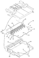
- FIG. 2 is a perspective view showing a state in which the conductive path module and the housing are separated.
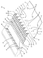
- FIG. 3 is an exploded perspective view of the conductive path module.
- FIG. 4 is a side sectional view of the sheet-shaped conductive path.
- FIG. 5 is a plan sectional view of a sheet-shaped conductive path.
- the sheet-shaped conductive path of the present disclosure is (1) With multiple terminal fittings A sheet-shaped flexible conductive member to which the plurality of terminal fittings are fixed, a positioning unit for positioning the plurality of terminal fittings in a state where the plurality of terminal fittings are not fixed to the sheet-shaped flexible conductive member, and the sheet. It is provided with a housing for accommodating the plurality of terminal fittings fixed to the flexible conductive member.
- the sheet-shaped conductive path of the present disclosure is provided with a positioning portion capable of positioning a plurality of terminal fittings in a state before being fixed to the sheet-shaped flexible conductive member, the plurality of terminal fittings can be positioned on the sheet-shaped flexible conductive member. It can be fixed in a positioned state with respect to.
- the positioning portion can position the plurality of terminal fittings in a state where the fixing portions of the plurality of terminal fittings with the sheet-shaped flexible conductive member are exposed, and the sheet-shaped flexible conductive member and the said. It is preferable that the plurality of terminal fittings are fixed by the soldered portion. According to this configuration, the terminal fitting and the sheet-shaped flexible conductive member can be fixed by reflow soldering or flow soldering.
- the positioning portion is a part separate from the housing and is formed of a holding member made of a material having higher heat resistance than the housing. According to this configuration, a plurality of terminal fittings positioned by the positioning portion can be fixed to the sheet-shaped flexible conductive member by reflow soldering.
- the positioning portion is formed on a holding member separate from the housing, and the holding member is formed with a locking portion for locking the sheet-shaped flexible conductive member. According to this configuration, a plurality of terminal fittings and a sheet-shaped flexible conductive member can be positioned.
- the housing contains a portion where the plurality of terminal fittings and the sheet-shaped flexible conductive member are fixed. According to this configuration, it is possible to prevent foreign matter from interfering with the fixed portion between the plurality of terminal fittings and the sheet-shaped flexible conductive member.
- the terminal fitting has an elongated connection portion, and the sheet-shaped flexible conductive member is formed with a plurality of connection holes through which the connection portion is penetrated, and the connection portion is formed by the soldering portion of the sheet. It is preferable that it is fixed to the flexible conductive member. According to this configuration, since the connecting portion is positioned on the sheet-shaped flexible conductive member by the connection hole, the plurality of terminal fittings and the sheet-shaped flexible conductive member can be fixed in an appropriate positional relationship.
- the plurality of terminal fittings have a common form of the terminal main body portion, and the plurality of first terminal fittings and the plurality of first terminal fittings having different extension lengths of the connection portion from the terminal main body portion.
- the positioning unit includes the second terminal fitting, and the positioning portion is positioned in a state where the plurality of first terminal fittings and the plurality of second terminal fittings are alternately aligned so that the terminal bodies are lined up in a row. It is preferable that the connection holes are staggered. According to this configuration, the pitch between the soldered portions of the adjacent connecting portions can be wider than the pitch between the adjacent first terminal fittings and the second terminal fittings. As a result, even if the pitch between the adjacent first terminal fittings and the second terminal fittings is narrow, it is possible to prevent a short circuit between the adjacent soldering portions.
- Example 1 embodying the sheet-shaped conductive path of the present disclosure will be described with reference to FIGS. 1 to 5. It should be noted that the present invention is not limited to these examples, and is indicated by the scope of claims, and is intended to include all modifications within the meaning and scope equivalent to the scope of claims.
- the front-back direction is defined as diagonally lower right in FIG. 1, diagonally upper left in FIGS. 2 and 3, and left in FIGS. 4 and 5, as forward.
- the directions appearing in FIGS. 1 to 4 are defined as upward and downward as they are.
- the lower side in FIG. 5 is defined as the left side
- the upper side is defined as the right side.
- the sheet-shaped conductive path of the first embodiment is configured by assembling the conductive path module 10 and the housing 50.
- the conductive path module 10 is configured by assembling a sheet-shaped flexible conductive member 11, a plurality of first terminal fittings 20, a plurality of second terminal fittings 30, and a holding member 40. Has been done.
- the sheet-shaped flexible conductive member 11 is made of a flexible printed circuit board (Flexible printed circuit boards), a flexible flat cable (Flexible Flat Cable), or the like.
- the sheet-shaped flexible conductive member 11 is formed by arranging a printed circuit (not shown) and a conductor (not shown) on a flexible sheet-shaped base material made of an insulating material.
- the sheet-shaped flexible conductive member 11 is arranged horizontally with the thickness direction facing up and down.
- the sheet-shaped flexible conductive member 11 has a band shape and extends long in the front-rear direction. As shown in FIGS. 3 and 5, the front end edge 11F of the sheet-shaped flexible conductive member 11 extends linearly in the left-right direction. At the front end of the sheet-shaped flexible conductive member 11, a pair of symmetrical overhanging portions 12 projecting to both the left and right sides are formed. A stepped retreat restricting portion 13 is formed at the rear end portion of the overhanging portion 12.
- a locking hole 14 is formed at the front end of both the left and right retreat restricting portions 13 so as to vertically penetrate the sheet-shaped flexible conductive member 11.
- the locking hole 14 has a rectangular shape with its long side facing in the front-rear direction.
- a plurality of (three in this embodiment) positioning holes 15 are formed in a region of the sheet-shaped flexible conductive member 11 behind the locking holes 14 with a space left and right.
- the same number of first connection holes 16 as the number of first terminal fittings 20 and the same number of second connection holes 17 as the number of second terminal fittings 30 are formed. ..
- a part of the printed circuit or the conductor is exposed at the hole edge portion of the first connection hole 16 and the hole edge portion of the second connection hole 17.
- the first connection hole 16 and the second connection hole 17 are in the form of vertically penetrating the sheet-shaped flexible conductive member 11. In a plan view, the first connection hole 16 and the second connection hole 17 are staggered.
- the plurality of first connection holes 16 are arranged in a row in parallel with the front end edge 11F of the sheet-shaped flexible conductive member 11 at regular intervals in the left-right direction.
- the plurality of second connection holes 17 are arranged in a row behind the first connection hole 16 at regular intervals in the left-right direction. In the left-right direction, the first connection hole 16 and the second connection hole 17 are arranged so as to be arranged alternately at a constant pitch.
- the first terminal fitting 20 has a square cylindrical first terminal main body 21 elongated in the front-rear direction and a first connection extending rearward from the rear end of the first terminal main body 21. It is a single component having a portion 22 and the like.
- a mating terminal provided on a mating connector (not shown) is inserted into and connected to the first terminal main body 21 from the front.
- a first wide portion 23 having the same width dimension as the first terminal main body portion 21 is formed at the front end portion of the first connection portion 22.
- the first connecting portion 22 is narrower than the first wide portion 23 and has an elongated first extending portion 24 extending rearward from the rear end of the first wide portion 23.
- the first connecting portion 22 has a first inserting portion 25 that is bent downward (in a direction approaching the sheet-shaped flexible conductive member 11) from the rear end of the first extending portion 24.
- the second terminal fitting 30 has a square cylindrical second terminal main body 31 elongated in the front-rear direction and a second connection portion 32 extending rearward from the rear end of the second terminal main body 31. It is a single part having and.
- a mating terminal provided on a mating connector (not shown) is inserted into and connected to the second terminal main body 31 from the front.
- a second wide portion 33 having the same width dimension as the first terminal main body portion 21 is formed at the front end portion of the second connection portion 32.
- the second connecting portion 32 is narrower than the second wide portion 33 and has an elongated second extending portion 34 extending rearward from the rear end of the second wide portion 33.
- the second connecting portion 32 has a second inserting portion 35 that is bent downward (in a direction approaching the sheet-shaped flexible conductive member 11) from the rear end of the second extending portion 34.
- the first terminal main body 21 and the second terminal main body 31 are parts having the same shape and size.
- the first wide portion 23 and the second wide portion 33 are also portions having the same shape and size.
- the first insertion portion 25 and the second insertion portion 35 are sites having the same shape and size.
- the length of the first extending portion 24 is shorter than that of the second extending portion 34 by the same dimension as the distance between the first connecting hole 16 and the second connecting hole 17 in the front-rear direction. That is, the first terminal fitting 20 and the second terminal fitting 30 have the same shape and dimensions except that the lengths of the first extending portion 24 and the second extending portion 34 are different.
- the holding member 40 is a single part made of a synthetic resin material.
- the heat resistant temperature (melting point) of the holding member 40 is higher than the temperature inside the reflow furnace (not shown) when reflow soldering is performed.
- a liquid crystal polymer (LCP) having a deflection temperature under load of 260 ° C. or higher can be used.
- LCP liquid crystal polymer
- FIGS. 3 to 5 a plurality of positioning portions 41 are formed side by side in the left-right direction inside the holding member 40.
- the positioning portion 41 is elongated in the front-rear direction and has a through-hole shape opened on the front surface and the rear surface of the holding member 40.
- the positioning portions 41 adjacent to each other on the left and right are partitioned by the partition wall portion 42.
- the parallel pitch in the left-right direction of the positioning portion 41 has the same dimension as the pitch of the first connection hole 16 and the second connection hole 17 adjacent to each other on the left and right.
- each positioning portion 41 has a front wall portion 43 constituting the front end surface of the holding member 40.
- the first terminal fitting 20 and the second terminal fitting 30 inserted into the positioning portion 41 are positioned in a state where the relative displacement forward with respect to the holding member 40 is restricted by abutting against the front wall portion 43. ..
- a protrusion-shaped retaining portion 45 is formed on the bottom wall portion 44 constituting each positioning portion 41.
- the first terminal fitting 20 and the second terminal fitting 30 inserted into the positioning portion 41 are attached to the holding member 40 by locking the locking projections 26 formed on the terminal body portions 21 and 31 to the retaining portion 45.
- the relative displacement to the rear is regulated.
- the first terminal main body 21 and the second terminal main body 31 are housed in the positioning portion 41, and the first connection portion 22 and the second connection portion 32 are exposed to the rear of the holding member 40 (positioning portion 41). There is.
- the first terminal fitting 20 in the positioning portion 41 is positioned in the left-right direction by sandwiching the first terminal main body portion 21 between the partition wall portions 42.
- the second terminal fitting 30 in the positioning portion 41 is positioned in the left-right direction by sandwiching the second terminal main body portion 31 between the partition wall portions 42.
- the plurality of positioned first terminal fittings 20 and second terminal fittings 30 have the same pitch as the pitches of the positioning portions 41 adjacent to each other on the left and right, and the pitches of the first connection holes 16 and the second connection holes 17 adjacent to each other on the left and right.
- All the first terminal fittings 20 and the second terminal fittings 30 are positioned in the left-right direction with respect to the holding member 40.
- the first terminal fitting 20 and the second terminal fitting 30 in the positioning portion 41 are vertically positioned with respect to the holding member 40 by being sandwiched between the upper surface and the lower surface of the positioning portion 41.
- a pair of symmetrical arm portions 46 are formed on the holding member 40.
- the arm portion 46 is in a cantilevered form extending rearward from the left and right ends of the holding member 40.
- a locking portion 47 projecting downward is formed at the rear end portion (extending end portion) of both arm portions 46.
- the housing 50 is configured by vertically overlapping the lower housing 51 and the upper housing 55.
- the lower housing 51 and the upper housing 55 are made of a synthetic resin material having a lower deflection temperature under load than the holding member 40.
- polybutylene terephthalate (PBT) can be used as an example of the material of the housing 50.
- a lower recess 52 is formed at the front end of the upper surface of the lower housing 51.
- the lower recess 52 accommodates the lower surface side portion of the holding member 40, thereby positioning the holding member 40 in the front-rear direction and the left-right direction.
- a plurality of (three in this embodiment) positioning protrusions 53 are formed at intervals in the left-right direction.
- a pair of left and right stoppers 54 forming a stepped shape in a plan view are formed on the inner surface of the side wall portion of the lower housing 51.
- An upper recess 56 is formed at the front end of the lower surface of the upper housing 55. The upper recess 56 accommodates the upper surface side portion of the holding member 40, thereby positioning the holding member 40 in the front-rear direction and the left-right direction.
- the manufacturing procedure of the sheet-shaped conductive path will be described.
- the first terminal fitting 20 and the second terminal fitting 30 are inserted into the positioning portion 41 from the rear of the holding member 40, and are brought into a retaining state by the retaining portion 45.
- the first terminal fitting 20 is inserted into a positioning portion 41 arranged at the same position as the first connection hole 16 of the sheet-shaped flexible conductive member 11 in the left-right direction.
- the second terminal fitting 30 is inserted into the positioning portion 41 arranged at the same position as the second connection hole 17 in the left-right direction. That is, the first terminal fitting 20 and the second terminal fitting 30 are inserted into the positioning portion 41 so as to be arranged alternately in the left-right direction.
- the plurality of first terminal fittings 20 and the plurality of second terminal fittings 30 inserted into the positioning portion 41 are positioned in the left-right direction with respect to each other, and at the same time, are positioned in the left-right direction with respect to the holding member 40.
- the holding member 40, the first terminal fitting 20, and the second terminal fitting 30 are brought close to the front end portion of the sheet-shaped flexible conductive member 11, and the locking portion 47 of the holding member 40 is engaged with the sheet-shaped flexible conductive member 11. It is fitted into the stop hole 14.
- the first insertion portion 25 of the first connection portion 22 is fitted into the first connection hole 16, and the second insertion portion 35 of the second connection portion 32 is fitted into the second connection hole 17.
- the conductive path module 10 temporarily assembled as described above is housed in a reflow furnace (not shown).
- the sheet-shaped flexible conductive member 11 is previously coated with a solder paste (not shown) along the hole edge portion of the first connection hole 16 and the hole edge portion of the second connection hole 17.
- the solder paste is heated and melted in the reflow furnace, the printed circuit or the conductor is connected to the first connection portion 22 at the hole edge portion of the first connection hole 16, and the second connection hole 17 is connected. At the hole edge portion, the printed circuit or conductor is connected to the second connecting portion 32.
- the molten solder paste is hardened to become the soldered portion 38 (see FIGS. 4 and 5)
- the first terminal fitting 20 (first connecting portion 22) and the second terminal fitting 30 (second connection) are formed.
- the portion 32) is conductively fixed to the sheet-shaped flexible conductive member 11. As described above, the production of the conductive path module 10 is completed.
- the conductive path module 10 is temporarily assembled to the lower housing 51.
- the holding member 40 is housed in the lower recess 52, the positioning hole 15 of the sheet-shaped flexible conductive member 11 is fitted into the positioning protrusion 53 of the lower housing 51, and the retreat restricting portion 13 of the overhanging portion 12 is fitted to the lower housing. It is locked to the stopper 54 of 51 from the front.
- the upper housing 55 is combined with the lower housing 51 so as to cover the conductive path module 10 to form the housing 50.
- the holding member 40 is positioned in the front-rear direction and the left-right direction with respect to the housing 50 by fitting into the lower recess 52 and the upper recess 56.
- the sheet-shaped flexible conductive member 11 is held in a state in which the relative displacement to the rear with respect to the housing 50 is restricted by engaging the overhanging portion 12 with the stopper 54.
- the entire holding member 40, the entire first terminal fitting 20, the entire second terminal fitting 30, and the front end portion of the sheet-shaped flexible conductive member 11 are housed inside the housing 50.
- a soldering portion 38 (a connecting portion between the second connecting portion 32 and the second connecting hole 17), which is a fixing portion between the second terminal fitting 30 and the sheet-shaped flexible conductive member 11, is also housed in the housing 50.
- the sheet-shaped conductive path of this embodiment includes a plurality of first terminal fittings 20, a plurality of second terminal fittings 30, a sheet-shaped flexible conductive member 11, a positioning portion 41, and a housing 50.
- a plurality of first terminal fittings 20 and a plurality of second terminal fittings 30 are fixed to the sheet-shaped flexible conductive member 11.
- the plurality of positioning portions 41 move the plurality of first terminal fittings 20 and the plurality of second terminal fittings 30 back and forth in a state where the first terminal fittings 20 and the second terminal fittings 30 are not fixed to the sheet-shaped flexible conductive member 11.
- the housing 50 accommodates a plurality of first terminal fittings 20 and a plurality of second terminal fittings 30 fixed to the sheet-shaped flexible conductive member 11.
- the sheet-shaped conductive path of this embodiment includes a positioning unit 41.
- the positioning unit 41 positions the plurality of first terminal fittings 20 and the plurality of second terminal fittings 30 in a state before being fixed to the sheet-shaped flexible conductive member 11. Since the sheet-shaped conductive path of the present embodiment is provided with the positioning portion 41, the plurality of first terminal fittings 20 and the plurality of second terminal fittings 30 are fixed to the sheet-shaped flexible conductive member 11 in a positioned state. can do.
- the positioning portion 41 has a plurality of first terminal fittings in a state where the fixing portions (soldered portions 38) to the sheet-shaped flexible conductive member 11 in the plurality of first terminal fittings 20 and the plurality of second terminal fittings 30 are exposed. It is possible to position the 20 and the plurality of second terminal fittings 30.
- the sheet-shaped flexible conductive member 11, the plurality of first terminal fittings 20, and the plurality of second terminal fittings 30 are fixed by a soldering portion 38. Therefore, the sheet-shaped flexible conductive member 11 can be fixed to the first terminal fitting 20 and the second terminal fitting 30 by reflow soldering.
- the positioning portion 41 is a separate part from the housing 50, and is formed on a holding member 40 made of a material having higher heat resistance than the housing 50. According to this configuration, the plurality of first terminal fittings 20 and the plurality of second terminal fittings 30 positioned by the positioning portion 41 can be fixed to the sheet-shaped flexible conductive member 11 by reflow soldering. Since the holding member 40 is formed with a locking portion 47 for locking the sheet-shaped flexible conductive member 11, the plurality of first terminal fittings 20, the plurality of second terminal fittings 30, and the sheet-shaped flexible conductive member 11 Can be positioned via the holding member 40.
- the housing 50 contains a fixing portion (soldering portion 38) between the plurality of first terminal fittings 20 and the plurality of second terminal fittings 30 and the sheet-shaped flexible conductive member 11, the soldering portion 38 is accommodated. It is possible to prevent the interference of foreign matter.
- the plurality of terminal fittings fixed to the sheet-shaped flexible conductive member 11 include a plurality of first terminal fittings 20 and a plurality of second terminal fittings 30 in which the terminal body portions 21 and 31 have a common form.
- the extension length of the first connection portion 22 from the first terminal main body 21 of the first terminal fitting 20 and the extension length of the second connection portion 32 from the second terminal main body 31 of the second terminal fitting 30 are It's different.
- the positioning unit 41 positions the plurality of first terminal fittings 20 and the plurality of second terminal fittings 30 in a state of being alternately aligned so that the first terminal main body 21 and the second terminal main body 31 are lined up in a row. ..
- the plurality of first connection holes 16 and the plurality of second connection holes 17 are staggered.
- the holding member is formed with a locking portion for locking the sheet-shaped flexible conductive member, but the holding member may be in a form having no locking portion.
- a plurality of first terminal fittings and second terminal fittings and a fixing portion between the sheet-shaped flexible conductive member are housed in the housing, but the plurality of first terminal fittings, the second terminal fittings and the sheet are accommodated.
- the portion fixed to the flexible conductive member may be exposed to the outside of the housing.
- the first connection portion and the second connection portion formed on the first terminal fitting and the second terminal fitting are passed through the first connection hole and the second connection hole of the sheet-shaped flexible conductive member.
- the terminal fitting and the second terminal fitting may be fixed in a surface mount form mounted on the surface of the sheet-shaped flexible conductive member.
- the first connection hole and the second connection hole are arranged in a staggered manner, but the first connection hole and the second connection hole may be arranged so as to be lined up in a row.
- Conductive path module 11 Sheet-shaped flexible conductive member 11F: Front end edge 12 of the sheet-shaped flexible conductive member ... Overhanging portion 13 ... Treatment restricting portion 14 ; Locking hole 15 ... Positioning hole 16 ; First connection hole (connection hole) ) 17 ... Second connection hole (connection hole) 20 ... 1st terminal fitting (terminal fitting) 21 ... 1st terminal main body 22 ... 1st connection 23 ... 1st wide part 24 ... 1st extension 25 ... 1st insertion part 26 ... Locking protrusion 30 ... 2nd terminal metal fittings (terminal metal fittings) 31 ... 2nd terminal main body 32 ... 2nd connection 33 ... 2nd wide portion 34 ... 2nd extension 35 ...
Landscapes
- Engineering & Computer Science (AREA)
- Manufacturing & Machinery (AREA)
- Coupling Device And Connection With Printed Circuit (AREA)
- Multi-Conductor Connections (AREA)
Priority Applications (2)
| Application Number | Priority Date | Filing Date | Title |
|---|---|---|---|
| CN202180088255.6A CN116648826A (zh) | 2021-01-05 | 2021-12-17 | 片状导电路径 |
| US18/270,797 US20240063563A1 (en) | 2021-01-05 | 2021-12-17 | Sheet-like conductive path |
Applications Claiming Priority (2)
| Application Number | Priority Date | Filing Date | Title |
|---|---|---|---|
| JP2021-000372 | 2021-01-05 | ||
| JP2021000372A JP2022105807A (ja) | 2021-01-05 | 2021-01-05 | シート状導電路 |
Publications (1)
| Publication Number | Publication Date |
|---|---|
| WO2022149442A1 true WO2022149442A1 (ja) | 2022-07-14 |
Family
ID=82357290
Family Applications (1)
| Application Number | Title | Priority Date | Filing Date |
|---|---|---|---|
| PCT/JP2021/046839 Ceased WO2022149442A1 (ja) | 2021-01-05 | 2021-12-17 | シート状導電路 |
Country Status (4)
| Country | Link |
|---|---|
| US (1) | US20240063563A1 (enExample) |
| JP (1) | JP2022105807A (enExample) |
| CN (1) | CN116648826A (enExample) |
| WO (1) | WO2022149442A1 (enExample) |
Citations (6)
| Publication number | Priority date | Publication date | Assignee | Title |
|---|---|---|---|---|
| JPH0658579U (ja) * | 1993-01-14 | 1994-08-12 | 矢崎総業株式会社 | 回路基板用コネクタ |
| JPH10284188A (ja) * | 1997-04-08 | 1998-10-23 | Toyama Parts:Kk | 表面実装型コネクター |
| JP2011253619A (ja) * | 2010-03-31 | 2011-12-15 | Fujikura Ltd | 防水コネクタ |
| JP2016110994A (ja) * | 2014-12-05 | 2016-06-20 | パナソニックIpマネジメント株式会社 | プラグコネクタ及びコネクタセット |
| WO2020105382A1 (ja) * | 2018-11-20 | 2020-05-28 | 株式会社オートネットワーク技術研究所 | コネクタ |
| WO2020241456A1 (ja) * | 2019-05-30 | 2020-12-03 | パナソニックIpマネジメント株式会社 | プラグハウジングおよびプラグコネクタ |
Family Cites Families (9)
| Publication number | Priority date | Publication date | Assignee | Title |
|---|---|---|---|---|
| JPH01134380U (enExample) * | 1988-03-09 | 1989-09-13 | ||
| JP3128568B2 (ja) * | 1996-03-25 | 2001-01-29 | 日本航空電子工業株式会社 | 電気コネクタの実装構造及びその実装に用いる治具 |
| US6752651B2 (en) * | 2001-09-12 | 2004-06-22 | Hung-Jen Chiu | Bus cable connector having bent soldering pins soldered to wire conductors |
| US7074073B2 (en) * | 2004-01-15 | 2006-07-11 | The Boeing Company | Electrical connector insert and apparatus and associated fabrication method |
| JP5324173B2 (ja) * | 2008-09-25 | 2013-10-23 | 日本圧着端子製造株式会社 | コネクタ及びコネクタの製造方法 |
| JP5232582B2 (ja) * | 2008-09-25 | 2013-07-10 | 日本圧着端子製造株式会社 | コネクタ |
| JP2016076318A (ja) * | 2014-10-03 | 2016-05-12 | ヒロセ電機株式会社 | 平型導体付電気コネクタ |
| JP7407389B2 (ja) * | 2019-08-02 | 2024-01-04 | パナソニックIpマネジメント株式会社 | プラグコネクタ及びそれを備えたコネクタセット並びにコネクタセットの抜去方法 |
| JP7094641B2 (ja) * | 2019-10-16 | 2022-07-04 | 矢崎総業株式会社 | コネクタ |
-
2021
- 2021-01-05 JP JP2021000372A patent/JP2022105807A/ja active Pending
- 2021-12-17 US US18/270,797 patent/US20240063563A1/en active Pending
- 2021-12-17 WO PCT/JP2021/046839 patent/WO2022149442A1/ja not_active Ceased
- 2021-12-17 CN CN202180088255.6A patent/CN116648826A/zh active Pending
Patent Citations (6)
| Publication number | Priority date | Publication date | Assignee | Title |
|---|---|---|---|---|
| JPH0658579U (ja) * | 1993-01-14 | 1994-08-12 | 矢崎総業株式会社 | 回路基板用コネクタ |
| JPH10284188A (ja) * | 1997-04-08 | 1998-10-23 | Toyama Parts:Kk | 表面実装型コネクター |
| JP2011253619A (ja) * | 2010-03-31 | 2011-12-15 | Fujikura Ltd | 防水コネクタ |
| JP2016110994A (ja) * | 2014-12-05 | 2016-06-20 | パナソニックIpマネジメント株式会社 | プラグコネクタ及びコネクタセット |
| WO2020105382A1 (ja) * | 2018-11-20 | 2020-05-28 | 株式会社オートネットワーク技術研究所 | コネクタ |
| WO2020241456A1 (ja) * | 2019-05-30 | 2020-12-03 | パナソニックIpマネジメント株式会社 | プラグハウジングおよびプラグコネクタ |
Also Published As
| Publication number | Publication date |
|---|---|
| CN116648826A (zh) | 2023-08-25 |
| US20240063563A1 (en) | 2024-02-22 |
| JP2022105807A (ja) | 2022-07-15 |
Similar Documents
| Publication | Publication Date | Title |
|---|---|---|
| JP7361839B2 (ja) | コネクタ | |
| CN101064389B (zh) | 扁平型导体用电连接器及具有扁平型导体的电连接器 | |
| US7374432B2 (en) | Connector | |
| US9985366B2 (en) | Board-to-board connector with metal fittings and guide portions | |
| KR101195355B1 (ko) | 위킹 방지 단자 및 커넥터 | |
| JP3225065B2 (ja) | 電気コネクタ | |
| TW201014060A (en) | Electrical connector | |
| CN109314330B (zh) | 表面安装型连接器 | |
| KR20170058274A (ko) | 전기 커넥터 | |
| US20220209446A1 (en) | Connector set and cap | |
| CN101641835B (zh) | 基板连接器 | |
| JP2015516109A (ja) | 印刷回路基板を相互接続するためのシステム | |
| JP4091702B2 (ja) | 誤差吸収コネクタ | |
| KR101452626B1 (ko) | 회로기판 수직 접속용 커넥터 조립체 | |
| JP7655777B2 (ja) | 端子、電線コネクタ及び電線対基板コネクタ | |
| JP5486885B2 (ja) | 電気コネクタおよびコネクタ | |
| CN104205500B (zh) | 印刷线路板上的端子的安装结构 | |
| JP7398054B2 (ja) | コネクタおよびコネクタの製造方法 | |
| WO2022149442A1 (ja) | シート状導電路 | |
| JP5473638B2 (ja) | 電気コネクタ | |
| CN101682126A (zh) | 用在焊接操作中的电连接器 | |
| CN114628920A (zh) | 连接器及端子配件 | |
| JP2010176924A (ja) | 基板用コネクタ及びコネクタを備えた配線基板 | |
| JP7779801B2 (ja) | フラットケーブル用コネクタ | |
| JP7744108B2 (ja) | ワイヤハーネス |
Legal Events
| Date | Code | Title | Description |
|---|---|---|---|
| 121 | Ep: the epo has been informed by wipo that ep was designated in this application |
Ref document number: 21916667 Country of ref document: EP Kind code of ref document: A1 |
|
| WWE | Wipo information: entry into national phase |
Ref document number: 202180088255.6 Country of ref document: CN |
|
| WWE | Wipo information: entry into national phase |
Ref document number: 18270797 Country of ref document: US |
|
| NENP | Non-entry into the national phase |
Ref country code: DE |
|
| 122 | Ep: pct application non-entry in european phase |
Ref document number: 21916667 Country of ref document: EP Kind code of ref document: A1 |