WO2022145269A1 - 被覆欠陥検出装置と被覆欠陥検出方法、および回転電機の製造方法 - Google Patents
被覆欠陥検出装置と被覆欠陥検出方法、および回転電機の製造方法 Download PDFInfo
- Publication number
- WO2022145269A1 WO2022145269A1 PCT/JP2021/046992 JP2021046992W WO2022145269A1 WO 2022145269 A1 WO2022145269 A1 WO 2022145269A1 JP 2021046992 W JP2021046992 W JP 2021046992W WO 2022145269 A1 WO2022145269 A1 WO 2022145269A1
- Authority
- WO
- WIPO (PCT)
- Prior art keywords
- discharge
- detection
- coating defect
- signal
- electrode
- Prior art date
- Legal status (The legal status is an assumption and is not a legal conclusion. Google has not performed a legal analysis and makes no representation as to the accuracy of the status listed.)
- Ceased
Links
Images














Classifications
-
- G—PHYSICS
- G01—MEASURING; TESTING
- G01R—MEASURING ELECTRIC VARIABLES; MEASURING MAGNETIC VARIABLES
- G01R31/00—Arrangements for testing electric properties; Arrangements for locating electric faults; Arrangements for electrical testing characterised by what is being tested not provided for elsewhere
- G01R31/12—Testing dielectric strength or breakdown voltage ; Testing or monitoring effectiveness or level of insulation, e.g. of a cable or of an apparatus, for example using partial discharge measurements; Electrostatic testing
-
- H—ELECTRICITY
- H01—ELECTRIC ELEMENTS
- H01B—CABLES; CONDUCTORS; INSULATORS; SELECTION OF MATERIALS FOR THEIR CONDUCTIVE, INSULATING OR DIELECTRIC PROPERTIES
- H01B13/00—Apparatus or processes specially adapted for manufacturing conductors or cables
Definitions
- the present application relates to a coating defect detection device, a coating defect detection method, and a manufacturing method of a rotary electric machine.
- a coil is used in which a wire formed of a conductor such as copper or aluminum is coated with an organic insulator coating and a coil of a coated conductor wire called a magnet wire is wound. .. If a pinhole or scratch occurs on the coating of the magnet wire, an abnormal current will flow due to a short circuit between the adjacent magnet wires or the stator core during operation of the rotary electric machine, and the coil will be heated abnormally and burned out. To.
- This application discloses a technique for solving the above-mentioned problems, and enables highly reliable defect detection without damaging the coated conductor which is the inspection target product.
- the coating defect detection device disclosed in the present application is connected to a traveling path forming mechanism that travels a coated conducting wire to form a traveling path, an AC power source that is arranged facing the coated conducting wire and applies an AC voltage, and is connected to the traveling path.
- Discharge detection electrode whose length along the line is set to be equal to or greater than the value obtained by multiplying the traveling speed of the coated lead wire by the period for one cycle of the AC voltage, the discharge generated between the discharge detection electrode and the coated lead wire.
- the coated lead wire It is characterized by being provided with a determination unit for determining whether or not there is a coating defect.
- the coating defect detecting method disclosed in the present application is a traveling path forming step in which a coated conducting wire is traveled to form a traveling path, and a discharge detecting electrode having a length of one cycle is attached to a discharge detecting electrode arranged opposite to the coated conducting wire.
- Discharge detection that detects the discharge generated between the discharge detection electrode and the coated conductor by applying an AC voltage with a frequency shorter than the value obtained by dividing the length along the traveling path by the traveling speed of the coated conductor.
- the measurement step for measuring the detection interval of the detected discharge signal, and the relationship between the detection interval and the time calculated from the applied AC frequency it is determined whether or not the coated lead wire has a coating defect. It is characterized by including a determination step of performing the above.
- the presence or absence of the coating defect is determined based on the detection interval of the discharge signal, so that the coated conductor wire, which is the inspection target product, is not damaged. , Highly reliable defect detection is possible.
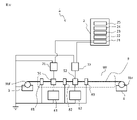
- FIG. It is a schematic diagram for demonstrating the structure of the coating defect detection apparatus which concerns on Embodiment 1.
- FIG. It is a figure which shows the example of the winding machine and the winding machine of the coated conductor which forms the traveling path formation mechanism in the covering defect detection apparatus which concerns on Embodiment 1.
- FIG. It is a perspective view which shows an example of the structure of the magnet wire which is the inspection target by the coating defect detection apparatus which concerns on Embodiment 1, or the detection method.
- It is a perspective view which shows the structure of the discharge detection electrode which constitutes the coating defect detection apparatus which concerns on Embodiment 1.
- FIG. It is a schematic diagram which shows the inspection target, the electric connection state of a discharge detection electrode, and a signal detector in the coating defect detection apparatus which concerns on Embodiment 1.
- FIG. 7A and 7B are waveform diagrams showing the relationship between the discharge signal detected by each of the two discharge detection electrodes and the applied voltage waveform in the coating defect detection device according to the first embodiment.
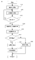
- 8A and 8B are schematic waveform diagrams showing measurement examples having different detection intervals in the coating defect detecting apparatus according to the first embodiment. It is a flowchart for demonstrating the operation of the coating defect detection apparatus which concerns on Embodiment 1, or the coating defect detection method. It is a block diagram which shows the structural example of the part which executes the arithmetic processing of the covering defect detection apparatus which concerns on Embodiment 1.
- FIG. It is a schematic diagram for demonstrating the structure of the coating defect detection apparatus which concerns on Embodiment 2.
- FIG. It is a schematic diagram for demonstrating the structure of the coating defect detection apparatus which concerns on the 2nd example of Embodiment 2.
- FIG. It is a schematic diagram for demonstrating the structure of the coating defect detection apparatus which concerns on Embodiment 3.
- FIG. It is a waveform diagram which shows the concept of the factor which reduces the measurement accuracy of the detection interval in the coating defect detection apparatus which concerns on Embodiment 3.
- FIG. It is a schematic diagram for demonstrating the structure of the coating defect detection apparatus which concerns on Embodiment 4.
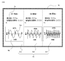
- FIG. It is a figure which shows the screen display example which displays the sampling result of the discharge signal waveform in the coating defect detection apparatus which concerns on Embodiment 4.
- FIG. 19 It is a schematic diagram for demonstrating the structure of the coating defect detection apparatus which concerns on Embodiment 5. It is a figure which shows the screen display example which displays the sampling result of the AC voltage waveform applied to the discharge detection electrode, and the discharge signal waveform in the coating defect detection apparatus which concerns on Embodiment 5.
- FIG. 19A and 19B respectively, are a coating defect detecting device and a stator core for explaining a combination of a coating defect detecting method and a stator core winding process as a method for manufacturing a rotary electric machine according to the sixth embodiment. It is a schematic diagram of each winding part of. It is a flowchart for demonstrating the manufacturing method of the rotary electric machine which concerns on Embodiment 6.
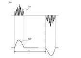
- FIG. 3 is a waveform diagram showing discharge signal waveforms before and after signal processing for explaining the first signal processing of a discharge signal in the coating defect detection device or the detection defect detection method according to the first embodiment.
- FIG. 3 is a waveform diagram showing discharge signal waveforms before and after signal processing for explaining a second signal processing of a discharge signal in the coating defect detection device or the detection defect detection method according to the first embodiment.
- FIG. 3 is a waveform diagram showing discharge signal waveforms before and after signal processing for explaining a third signal processing of a discharge signal in the coating defect detection device or the detection defect detection method according to the first embodiment.
- Embodiment 1. 1 to 9 are for explaining the configuration and operation of the coating defect detection device according to the first embodiment, and FIG. 1 is a traveling of a magnet wire to be inspected for the configuration of the coating defect detection device.
- FIG. 1 is a traveling of a magnet wire to be inspected for the configuration of the coating defect detection device.
- FIG. 2 is a diagram showing an example of a magnet wire feeding machine and a winder that function as a traveling path forming mechanism for forming a traveling path
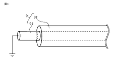
- FIG. 3 is a diagram showing an example of a magnet wire to be inspected.
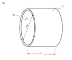
- FIG. 4 is a perspective view showing the structure of the discharge detection electrode constituting the coating defect detection device.
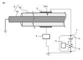
- FIG. 5 is a schematic diagram showing the magnet wire to be inspected, the electric connection state during the inspection of the discharge detection electrode and the signal detector
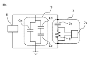
- FIG. 6 is the magnet wire to be inspected, the discharge detection electrode and the signal detection. It is an equivalent circuit diagram which shows the electric connection state during inspection of a device.
- FIGS. 8A and 7B are waveform diagrams showing the relationship between the discharge signal and the applied voltage waveform detected by the first discharge detection electrode and the second discharge detection electrode applied at different voltage frequencies, respectively, FIGS. 8A and 7B.
- Each of 8B is a schematic waveform diagram showing a measurement example in which the detection interval t of the discharge signal detected by the discharge detection electrode is different
- FIG. 9 is a flowchart for explaining the operation of the coating defect detecting device or the coating defect detecting method.
- the coating defect detecting device 1 of the magnet wire 9 (coated lead wire) of the present application detects the coating defect 92d (FIG. 5) of the magnet wire 9 before winding, and detects the traveling path Wr. It is configured so that the magnet wire 9 formed and running can be inspected.
- a bobbin 9bf for sending out a magnet wire 9 and a bobbin 9br for winding up are installed before and after the traveling path Wr, and a feeding machine 3 and a winding machine 4 are provided for the bobbin 9bf for sending out the magnet wire 9 and the bobbin 9br for winding up, respectively. It is arranged.
- the feeding machine 3 and the winding machine 4 are configured to function as a traveling path forming mechanism for forming a traveling path Wr in which the magnet wire 9 travels at a constant speed by adjusting the traveling speed Sr of the magnet wire 9. ..
- Various configurations can be applied to the feeding machine 3 and the winding machine 4, and for example, as shown in FIG. 2, a turntable 3T and a turntable 4T may be used.
- the magnet wire 9 is composed of a wire 91 and a coating film 92 covering the wire 91, and the magnet wire 9 to be inspected has the coating 92 at the end portion peeled off and the wire wire 9. 91 is grounded. Then, two discharge detection electrodes 5 (first discharge detection electrode 51 and second discharge detection electrode 52) configured to surround the magnet wire 9 are arranged in the traveling path Wr of the magnet wire 9.
- the AC power supply 6 is connected to each of the discharge detection electrodes 5 and applies a relatively low voltage in the corona discharge region, for example, an AC voltage of less than 1 kV at a predetermined frequency f.
- a second AC power supply 62 for applying an AC voltage is connected.
- the frequency f 1 and the frequency f 2 are set to different values, but the values are not limited to these and may be the same.
- a signal detector 7 (first signal detector 71 and second signal detector 72) connected to each of the discharge detection electrodes 5 and for detecting an electric signal from the discharge detection electrode 5 to which an AC voltage is applied is provided. I have. Then, the control device 2 that controls the coating defect detection operation in the coating defect detecting device 1 and detects the coating defect 92d (FIG. 5) of the magnet wire 9 based on the signal detected by the signal detector 7 is provided.
- the control device 2 includes an A / D converter 21 that digitally converts an analog signal detected by the signal detector 7, a storage device 22 that stores the A / D converted data, and a discharge signal Sa (discharge signal Sa) from the obtained data.
- a measuring device 23 for measuring the detection interval t (FIG. 8) in FIG. 7) is provided.
- a time difference calculation unit 24 that performs time difference processing of the measured detection interval t according to the position of the discharge detection electrode 5, and a determination unit 25 that determines the presence or absence of a coating defect 92d from the relationship between the time difference processed detection interval t and the frequency f. Is provided.
- each of the AC power supplies 6 is grounded in the same manner as the wire 91.
- the electrode length L along the wire traveling direction of each discharge detection electrode 5 is determined by the traveling speed Sr of the magnet wire 9 and the time ⁇ set to be equal to or longer than the time for one cycle of the AC voltage applied to each discharge detection electrode 5. , Determined as in equation (1).
- L Sr ⁇ ⁇ ⁇ ⁇ ⁇ (1)
- the discharge detection electrode 5 The electrode length L is 16.7 mm or more according to the equation (2).
- L ⁇ 1000 ⁇ (1/60) 16.7 ⁇ ⁇ ⁇ (2)
- the electrode length L 1 of the first discharge detection electrode 51 and the electrode length L 2 of the second discharge detection electrode 52 are set to different lengths according to the equation (2). May be good. However, when the lengths are the same, the electrode length L calculated for the discharge detection electrode 5 to which the voltage having the lowest frequency f is applied may be adjusted.
- the discharge detection electrode 5 is formed so as to be in contact with the entire circumference of the magnet wire 9 or to face each other at a certain distance, and may be formed in a cylindrical shape as shown in FIG.
- the axial direction of the cylinder may be aligned with the traveling direction of the magnet wire 9, and the axial length (electrode length L) may be determined by the traveling speed Sr and the frequency f according to the equation (1).
- it may be formed of a metal material such as copper, aluminum or iron, or a resin material in which a metal material such as conductive rubber or aluminum is continuously vapor-deposited from the inner surface 5fi to the connection portion with the AC power supply 6. It may be formed.
- the inner diameter Dei of the cylinder may be formed so as to be in contact with the magnet wire 9 in combination with the outer diameter of the magnet wire 9, or 10 or more and 100 ⁇ m or less in order to avoid scratching of the coating film 92 due to contact. It can also be formed with a margin of.
- the signal detector 7 is provided with a coupling capacitor 7c, a detection resistor 7r, and a voltage measuring device 7s for measuring the voltage of the detection resistor 7r. Therefore, when the magnet wire 9 to be inspected is passed through the discharge detection electrode 5 described above, the AC power supply 6 ACs to the coating film 92, the coupling capacitor 7c connected in parallel to the coating film 92, and the detection resistor 7r. A voltage will be applied.
- the coating defect 92d is a pinhole or a scratch generated in the coating 92.
- the voltage measuring instrument 7s detects the fluctuation of the AC voltage as a voltage value generated across the detection resistor 7r.
- the discharge charge q does not flow through the detection resistance 7r, no voltage is generated across the detection resistance 7r, but when the discharge charge q flows, the generated voltage ⁇ V is detected according to the equation (3).
- ⁇ V Rd ⁇ q ⁇ ⁇ ⁇ (3)
- Rd is the impedance of the detection resistor 7r.
- the first discharge detection electrode 51 detects the discharge signal Sa as shown in FIG. 7A.
- the discharge signal Sa maintains a constant phase angle with respect to the voltage waveform Sp with reference to the zero crossing point, and is a time interval corresponding to a half cycle on the positive electrode side and the negative electrode side. It is detected by and is detected twice in one cycle. Then, even in the second discharge detection electrode 52 having a different frequency f, as shown in FIG.
- the discharge signal Sa maintains a constant phase angle with respect to the voltage waveform Sp with reference to the zero crossing point, and is half of the positive electrode side and the negative electrode side. It is detected at time intervals corresponding to the cycle, and is detected twice in one cycle.
- the detection interval t 2 measured with respect to the second discharge detection electrode 52 is 1 ⁇ 2 of the detection interval t 1 measured with respect to the first discharge detection electrode 51. This relationship depends on the multiple ratio of the voltage frequency applied to the two electrodes.
- the detection interval t 2 measured with respect to the second discharge detection electrode 52 for a certain coating defect 92d is the first discharge detection electrode. It was found that the detection interval t1 measured with respect to 51 is 1 / n. Furthermore, it was found that the relationship is observed regardless of the traveling speed Sr.
- the applied voltage frequency applied to the second and subsequent discharge detection electrodes 5 is, for example, twice or three times the applied voltage frequency f1 applied to the first electrode. ..., set to n times. Then, the detection interval t measured for each discharge detection electrode 5 is 1/2, 1/3, ..., 1 with respect to the detection interval t1 measured for the first electrode. When it becomes / n, it can be determined that the discharge signal Sa is from the same coating defect 92d.
- the discharge (discharge signal Sa) due to the coating defect 92d of the magnet wire 9 is ensured against noise discharge caused by the measurement environment such as instability of the gap distance from the discharge detection electrode 5 or slight fluctuation of the ground potential. It is possible to determine the presence or absence of the coating defect 92d. This is because the discharge signal Sa from the coating defect 92d is generated while maintaining a constant phase angle with respect to the applied voltage waveform Sp.
- the discharge generated near the zero cross is illustrated, but the phase angle at which the discharge is generated is limited to this. Do not mean. If it is detected at the same phase angle position with respect to the zero cross, the detection interval t can be the same as the detection interval t when observed on the zero cross, even if it is far from the zero cross.
- the discharge signal Sa detected twice or more by each discharge detection electrode 5 is converted into a discharge signal waveform by the signal detector 7, and a constant sampling frequency is converted by the A / D converter 21. After A / D conversion with, it is stored in the storage device 22.
- the measuring device 23 measures the detection interval t of each of the discharge detection electrodes 5 from the stored data.
- the detection interval t is determined by various measurement methods such as the interval between the maximum peaks Px of each discharge signal Sa shown in FIG. 8A, the interval between the head peak Phs of each discharge signal Sa shown in FIG. 8B, and the average value thereof. Can be measured.
- a plurality of detection intervals t may be measured by arranging three or more discharge signals. In that case, an average value may be used, or any of the following, except for those showing a value different from the others.
- the detection interval t may be adopted as a representative value.
- the maximum peak Px of each discharge signal Sa shown in FIG. 8A may fluctuate due to vibration during traveling of the magnet wire 9, difference in surface shape and depth of the coating defect 92d of the magnet wire 9, etc., and each discharge signal. It may be difficult to find the maximum peak Px of Sa. Therefore, a method of signal waveform processing for easily finding the maximum peak Px of each discharge signal Sa even in such a case will be described.
- 22 to 24 are for explaining the first signal processing to the third signal processing, respectively, and the upper row shows the signal waveform before processing and the lower row shows the signal waveform after processing.
- the absolute value of the discharge signal Sa is compared with the threshold value Th, the portion above the threshold value Th is set to "1", and the portion below the threshold value Th is set to "0".
- the discharge signal Sa is converted into the signal Sa1.
- the maximum peak Px can be easily found and the detection interval t can be accurately measured.
- the discharge signal Sa of the coating defect 92d of the magnet wire 9 is shown as an ideal example.
- the head peak Ph cannot be clearly defined, and it may be difficult to calculate the detection interval t. Therefore, as the second signal processing, as shown in FIG. 23, the discharge signal Sa is converted into the signal Sa2 which has been smoothed by applying, for example, a low-pass filter. As described above, by using the signal Sa2 obtained by processing the raw discharge signal Sa, the head peak Ph can be easily determined and the detection interval t can be accurately measured.
- noise such as noise Sn1 and noise Sn2 may be added to the discharge signal Sa as shown in FIG. 24.
- the discharge signal Sa having noise such as noise Sn1 and noise Sn2 is converted into the signal Sa3 from which the noise is removed by applying a high-pass filter. Then, if the first signal processing or the second signal processing is used for the signal Sa3, the detection interval t can be measured more accurately.
- the time difference calculation unit 24 performs a time difference calculation process of the acquisition time (measurement time) in order to align the position of the discharge detection electrode 5 corresponding to the measured detection interval t on the magnet wire 9.
- the ratio of the detection interval t of the discharge signal Sa detected by the first discharge detection electrode 51 and the second discharge detection electrode 52 corresponding to the same position in the traveling direction of the magnet wire 9 is applied to each.
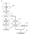
- the magnet wire 9 is passed from the bobbin 9bf toward the bobbin 9br so as to pass through each discharge detection electrode 5, and is wound in the traveling path Wr by winding by the winder 4 (step S100). In that state, an AC voltage is applied to each discharge detection electrode 5 at a frequency f set, and the discharge signal Sa is measured (step S110).
- step S120 When a signal such as the discharge signal Sa is detected (“Yes” in step S120), the detection interval t at each of the discharge detection electrodes 5 is measured, and the time difference process is executed (step S130). Then, the detection interval t of each discharge detection electrode 5 is analyzed (step S140), and the ratio n of the frequency f described above is used to determine whether or not the relationship is the reciprocal of n (step S150).
- step S150 when there is a reciprocal relationship (“Yes” in step S150), it is determined that there is a coating defect (step S200), for example, the time difference calculation unit 24 calculates the defect position and notifies the calculated position. (Step S210) and other corresponding processes are performed. On the other hand, if there is no reciprocal relationship in the assumed range (“No” in step S150), it is determined that there is no coating defect (step S300), and the process ends. Although not particularly described in the flow, these steps may be continued until, for example, the magnet wire 9 wound around the bobbin 9bf disappears.
- the data of the detection interval t from the plurality of discharge detection electrodes 5 is used.
- An example of determining the presence or absence of a coating defect 92d is shown, but the present invention is not limited to this. For example, by utilizing the phenomenon that the discharge signal Sa appears every half cycle at a constant phase angle with zero cross, whether or not there is a coating defect 92d depends on whether or not the interval between the two discharge signals Sa matches the half cycle. You may decide.
- one discharge detection electrode 5 having an electrode length L capable of measuring three or more discharge signals Sa is provided, and two measured from three or more signals are provided.
- the presence or absence of the coating defect 92d may be determined based on whether or not the above intervals match.
- noise peculiar to the AC power supply 6 can be separated by dividing the discharge detection electrode 5 and connecting a different AC power supply 6 to each.
- setting different frequencies for the plurality of discharge detection electrodes 5 has the advantage of being more resistant to noise.
- the discharge signal Sa may utilize the phenomenon of appearing while reversing the positive and negative directions, and the determination unit 25 may select a signal whose polarity is alternately reversed as a determination target for defect detection. Further, the noise reduction efficiency is improved. Further, instead of selecting the signals whose positive and negative are reversed, it is possible to improve the capture rate of the coating defect 92d by adding a signal having a weak intensity to the determination target.
- the control device 2 when the execution portion of the arithmetic processing is configured by the software using the microcomputer, the control device 2 includes the processor 201 and the storage device 202 as shown in FIG. It is also conceivable to configure it by one microcomputer 200 equipped with the above.
- the storage device 202 includes a volatile storage device such as a random access memory and a non-volatile auxiliary storage device such as a flash memory. Further, the auxiliary storage device of the hard disk may be provided instead of the flash memory.
- the processor 201 executes the program input from the storage device 202. In this case, the program is input from the auxiliary storage device to the processor 201 via the volatile storage device. Further, the processor 201 may output data such as a calculation result to the volatile storage device of the storage device 202, or may store the data in the auxiliary storage device via the volatile storage device.
- Embodiment 2 In the first embodiment, an example in which a discharge detection electrode for applying an AC voltage to detect a discharge is arranged on the traveling path of the magnet wire has been described. In the second embodiment, an example in which a static elimination electrode for statically eliminating the charged magnet wire is added to the traveling path will be described with respect to the first embodiment.
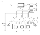
- FIG. 11 is a schematic diagram showing the relationship between the configuration of the coating defect detection device according to the second embodiment and the traveling path of the magnet wire to be inspected
- FIG. 12 is the coating defect detection according to the second example of the embodiment. It is a schematic diagram which shows the relationship with the traveling path of the magnet wire which is the inspection target about the structure of the apparatus.
- the configuration and operation other than the static elimination electrode are the same as those described in the first embodiment, the description of the same portion is omitted, and FIGS. 2 to 10 used in the first embodiment are incorporated.
- the coating 92 of the magnet wire 9 may be positively or negatively charged due to friction with a guide sheave (not shown) in the traveling path Wr or other constituent members. In that case, by canceling a part of the applied AC voltage on the positive electrode side or the negative electrode side, the discharge signal Sa from the coating defect 92d in the positive electrode side phase or the negative electrode side phase becomes unstable. As a result, the measured value of the detection interval t may vary, and as a result, the coating defect 92d may be overlooked.
- the static elimination electrode 8 having one end grounded on the upstream side of the traveling path Wr of the magnet wire for each of the discharge detecting electrodes 5.
- the charge of the coating film 92 was eliminated by providing the coating film 92. More specifically, the first static elimination electrode 81 is arranged on the upstream side of the first discharge detection electrode 51, and the second static elimination electrode 82 is arranged on the downstream side of the first discharge detection electrode 51 and upstream of the second discharge detection electrode 52. was placed.
- the first static elimination electrode 81 installed on the upstream side of the first discharge detection electrode 51 receives a charge due to friction between the bobbin 9bf that sends out the magnet wire 9 and the first discharge detection electrode 51. Eliminate static electricity.
- the second static elimination electrode 82 installed on the upstream side of the second discharge detecting electrode 52 eliminates the charged charge due to friction between the bobbin 9bf and the second second discharge detecting electrode 52, and at the same time, first. Charges charged by applying an AC voltage to the discharge detection electrode 51 can be eliminated.
- a third static elimination electrode 83 is provided on the downstream side of the most downstream discharge detection electrode 5, and in this example, on the downstream side of the second discharge detection electrode 52. ..
- the charged charge due to the application of the AC voltage at the most downstream discharge detection electrode 5, that is, the second discharge detection electrode 52 can be eliminated, and the generation of the coating defect 92d due to the subsequent charge charge discharge in the traveling path Wr can be prevented. Therefore, it is more suitable.
- Embodiment 3 In the third embodiment, an example in which a countermeasure against a sudden discharge is added in addition to the countermeasure against the electric charge in the second embodiment will be described.
- 13 and 14 are for explaining the configuration and operation of the coating defect detection device according to the third embodiment, and FIG. 13 is a traveling path of the magnet wire to be inspected for the configuration of the coating defect detection device.
- FIG. 14 is a schematic diagram showing the relationship with the above, and FIG. 14 is a waveform diagram showing the concept of factors that reduce the measurement accuracy of the detection interval, which is the target of countermeasures in the present embodiment.
- the configuration and operation other than the measures against sudden discharge are the same as those described in the first and second embodiments, and the description of the same parts is omitted and the figure used in the first embodiment is omitted. 2 to 10 are used.
- the same degree as the discharge signal Sa due to the coating defect 92d As a factor that lowers the measurement accuracy of the detection interval t, as shown in FIG. 14, the same degree as the discharge signal Sa due to the coating defect 92d.
- the generation of noise Sn due to the sudden discharge of the intensity of the above can be mentioned.
- Such a discharge has no regularity with respect to the applied voltage waveform Sp and occurs randomly. For example, when the noise Sn called spike noise is mistakenly recognized as the peak of the discharge from the coating defect 92d and the detection interval t is measured, the measured value varies.
- the third discharge detection electrode 53 is provided downstream of the third static elimination electrode 83 shown in the second example of the second embodiment. I tried to provide it.
- the third discharge detection electrode 53 is also connected to the third AC power supply 63 and the third signal detector 73, and a fourth static elimination electrode 84 is further provided downstream thereof.
- step S150 if the determination unit 25 satisfies the relationship that the detection interval t is the reciprocal multiple of the frequency multiple ratio in at least two discharge detection electrodes 5 out of the three discharge detection electrodes 5. , It may be determined that there is a coating defect 92d.
- the frequency f2 of the second discharge detection electrode 52 is n times the frequency f1 of the first discharge detection electrode 51
- the frequency f2 of the third discharge detection electrode 53 is m times, that is, the frequency.
- the voltage of frequency f3, which is n ⁇ m times that of f1 is set to be applied.
- the detection interval t 1 at the first discharge detection electrode 51, the detection interval t 2 at the second discharge detection electrode 52, and the detection interval t 3 at the third discharge detection electrode 53 are used, the presence / absence of a coating defect 92d is used. Can be determined using the combination of the following conditions A to D.
- condition X if any one of the conditions B and C is satisfied (condition X is not satisfied), it is determined as "yes” in step S150.
- the determination condition can be changed in consideration of the priority of noise reduction and the capture rate, such as determining "Yes" when both the condition B and the condition C (condition A) are satisfied.
- the criterion for determining the coating defect 92d in the first embodiment and the second embodiment is only condition B, provided that the ratio of the detection interval t is a condition.
- the coating defect 92d can be detected by the combination of the condition B and the condition C only by increasing the discharge detection electrode 5 by one, and the detection accuracy and the degree of freedom in setting the judgment standard are improved. do.
- the inspection time may increase and the production capacity may be impaired, but the optimum number of discharge detection electrodes may be determined in advance by experiments or the like.
- the detection interval t instead of the ratio of the detection interval t, the detection interval t may be determined based on the degree of coincidence with the half-cycle time calculated from the frequency f.
- the number of the discharge detection electrodes 5 is added to the second embodiment using the static elimination electrode 8 is shown, but the present invention is not limited to this.
- the number of discharge detection electrodes 5 may be added to the example of the first embodiment in which the countermeasure against coating charge is not described.
- Embodiment 4 In the above-described first to third embodiments, the display of the measurement data is not mentioned.
- the fourth embodiment a configuration for displaying the measurement data on the screen will be described.
- 15 and 16 are for explaining the configuration and operation of the coating defect detection device according to the fourth embodiment, and FIG. 15 is a traveling path of a magnet wire to be inspected for the configuration of the coating defect detection device.
- FIG. 16 is a schematic diagram showing the relationship with the above, and is a diagram showing a screen display example for displaying the sampling result of the discharge signal waveform which is the measurement result at each discharge detection electrode.
- the configurations and operations other than the screen display are the same as those described in the first to third embodiments, and the description of the same parts is omitted, and FIGS. 2 to 10 used in the first embodiment are shown. Use it.
- an image display device 2g for displaying measurement data obtained at the time of measurement and an image display device 2g for generating display data are generated.
- a display data generation unit 26 for outputting to is provided.
- the display data generation unit 26 has a function of generating display data for displaying the measurement data used for the determination on the image display device 2g when the determination unit 25 determines that there is a discharge from the coating defect 92d.
- a graphic display Dg showing the latest signal waveform at the time of determination for each discharge detection electrode 5, a measured detection interval t, and the like are displayed.
- the text display Dt combined with the applied voltage frequency f is displayed.
- the layout of the display screen Di is divided into sections (first section Di2, second section Di3, third section Di3) for each discharge detection electrode 5, and the measurement information of each discharge detection electrode 5 is aggregated for each section. The example shown is shown, but it is not limited to this.
- Embodiment 5 the waveform of the AC voltage applied to the discharge detection electrode itself is not mentioned.
- the waveform of the AC voltage applied to the discharge detection electrode itself is not mentioned.
- the fifth embodiment a configuration in which a signal from an AC power source is taken in and a waveform of an AC voltage is displayed will be described. 17 and 18 are for explaining the configuration and operation of the coating defect detection device according to the fifth embodiment, and FIG. 17 is a traveling path of a magnet wire to be inspected for the configuration of the coating defect detection device.
- FIG. 18 is a schematic diagram showing the relationship with the above, and is a diagram showing a screen display example for displaying the sampling result of the discharge signal waveform which is the measurement result at each discharge detection electrode.
- the signal from each AC power supply 6 is configured to be taken into the control device 2. Then, the AC voltage waveform from each AC power supply 6 applied to the discharge detection electrode 5 is A / D converted by the A / D converter 21 at a constant sampling frequency, and then stored in the storage device 22 to be stored in the storage device 22. A function of outputting to the image display device 2g is added via 26.
- the control of the start of sampling of the AC voltage waveform may be started, for example, by triggering the start of sampling of the discharge waveform signal of the first discharge signal Sa among the discharge signals Sa detected by each discharge detection electrode 5. ..
- the start time may be shifted in consideration of the time difference according to the traveling speed Sr and the arrangement position. .. Further, the stop control may be stopped after sampling is continued for a time ⁇ corresponding to one cycle or more of the AC voltage described in the first embodiment.
- the AC voltage waveform sampled in this way is displayed superimposed on the discharge signal waveform described in the fourth embodiment.
- the waveform display Gw showing the applied voltage waveform Sp is displayed together with the discharge signal waveform.
- the operator confirms that the signal determined to be a discharge from the coating defect 92d is generated at any time while maintaining a constant phase angle with respect to the applied voltage waveform Sp, and the determination is valid. can do.
- a scale showing the length of the detection interval t not shown and the length of half a cycle, or a scale showing the reciprocal of the ratio of the detection interval t to the frequency f of the other discharge detection electrodes is displayed. Then, it can be visually confirmed that the judgment is appropriate.
- Embodiment 6 a method of manufacturing a rotary electric machine with a magnet wire having no coating defect by using the coating defect detecting device or the detecting method described in the above-described first to fifth embodiments will be described.
- 19 to 21 are for explaining the manufacturing method of the rotary electric machine according to the sixth embodiment
- FIG. 19 is a diagram for explaining the combination of the coating defect detecting method and the winding process of the stator core.
- FIG. 19A shows a portion upstream of the winder and a schematic diagram (FIG. 19A) connected to the downstream side of the J portion of FIG.
- FIG. 19B shows the winding part of the stator core (unit core) corresponding to the winder part in.
- FIG. 20 is a flowchart for explaining a method for manufacturing a rotary electric machine
- FIG. 21 is viewed from an extension of a rotary shaft showing a configuration of a rotary electric machine manufactured by the method for manufacturing a rotary electric machine described with reference to FIGS. 19 and 20. It is a front view of the main component of the time.
- the parts corresponding to the inspection devices or the inspection methods described in the first to fifth embodiments are the same as those described in the first to fifth embodiments except for the winding machine. Yes, the description of the same part is omitted, and FIGS. 2 to 10 used in the first embodiment are incorporated.
- FIGS. 19A, 19B, and 20 As shown in FIGS. 19A, 19B, and 20, as shown in FIGS. 19A, 19B, and 20, as shown in FIG. , Or incorporated into the winding process of the stator 102, which is the armature of the linear motion machine.
- the unit iron core 102i constituting the unit stator 102t for forming the annular stator 102 is drawn.
- step S100 the magnet wire 9 is passed through each discharge detection electrode 5, and the bobbin 9bf is wound around the unit iron core 102i via the winding nozzle 9n of the winding machine (not shown) to travel.
- the vehicle is driven in the road Wr (step S100A).
- steps S110 to S140 described in the first to fifth embodiments are executed and the detection interval t satisfies, for example, the conditions A to D described in the third embodiment (“Yes” in step S150).
- step S200 It is determined that there is a coating defect (step S200).
- the measuring device 23 starts timer measurement with reference to the time T calculated by the time difference calculation unit 24 at the same time as the input from the time difference calculation unit 24 is received. Therefore, when the measuring device 23 completes the measurement, the unit iron core 102i in the winding operation is specified and notified (step S210). Further, the unit iron core 102i (corresponding product) determined to have a defect in the winding is ejected so as not to be mixed into the product (step S250).
- the traveling speed Sr may change depending on the winding location, but the location of the coating defect 92d can be specified based on the changing traveling speed Sr.
- the coil 102c is completed, and for example, a stator assembly is performed as a unit stator 102t in which a set of eight is combined in an annular shape to form the stator 102. It is sent to the step (step S400). That is, by executing the coating defect detection method described in the first to fifth embodiments in the winding step of forming the coil 102c, the unit stator 102t in which the coil 102c is combined with the unit iron core 102i is created. Then, the rotary electric machine 100 as shown in FIG. 21 is formed by coaxially arranging the rotor 101 assembled in the rotor assembly step (step S500) executed in parallel and fixing the outer circumference with the frame 103. To.
- the unit stator 102t which is identified as containing the coating defect 92d in the magnet wire 9, is not discharged to the subsequent processes and is transferred to a conveyor, a trolley, etc. for discharging defective products. It can be distinguished from a non-defective product by means such as (step S250). It is possible that the magnet wire 9 may stop running due to the stop of the winding machine before the measuring device 23 completes the measurement for a predetermined time. However, in that case, the measuring device 23 receives the winding stop signal from the winding machine and stops the measurement until the winding is restarted, or the winding is always in operation during winding. It is sufficient to receive the signal of and continue the measurement only while receiving the signal.
- the rotary electric machine 100 can be formed by the stator 102 formed only of the magnet wire 9 that does not include the coating defect 92d. Further, the defective stator may be individually inspected again by a known method such as a surge voltage application (impulse voltage application) test, and if it passes, it may be incorporated into step S400. Alternatively, if the coating defect 92d can be repaired by unwinding the winding, the coating defect 92d may be incorporated into step S100A after the repair.
- a surge voltage application impulse voltage application
- a relatively low voltage in the corona discharge region for example, an AC voltage of less than 1 kV, without generating a spark discharge is used. Is applied, and the presence or absence of the coating defect 92d is determined by the detection interval t. Therefore, even if a high voltage that damages the coating film 92 is not applied, the discharge signal Sa can be distinguished from noise and the presence or absence of the coating defect 92d can be accurately determined, so that the coating defect 92d can be detected nondestructively and accurately. Then, the rotary electric machine 100 can be formed by the sound magnet wire 9.
- the traveling mechanism for forming the traveling path Wr by traveling the coated conducting wire (magnet wire 9), facing the coated conducting wire. It is connected to an AC power supply 6 that is arranged and applies an AC voltage, and the length (electrode length L) along the traveling path Wr is the traveling speed Sr of the coated lead wire multiplied by the period of one cycle of the AC voltage.
- the discharge detection electrode 5 set above the value, the discharge detector (signal detector 7) that detects the discharge generated between the discharge detection electrode 5 and the coated lead wire, and the detection interval t of the discharge signal Sa detected by the discharge detector.
- the presence or absence of the coating defect 92d can be determined without generating a spark discharge by applying a relatively low AC voltage in the corona discharge region.
- highly reliable defect detection becomes possible without damaging the magnet wire 9 which is the inspection target product.
- the determination unit 25 determines whether or not the coated conductor has a coating defect 92d depending on whether or not the detection interval t corresponds to a half cycle of the AC voltage, the influence of noise can be affected. By eliminating it, the coating defect 92d can be detected accurately.
- the discharge detection electrode 5 is composed of a plurality of discharge detection electrodes 5 separately arranged at distant positions along the traveling path Wr, and the determination unit 25 is a detection interval measured for each of the plurality of discharge detection electrodes 5. Whether or not the coated conductor has a coating defect 92d is determined based on whether or not the ratio of t has a reciprocal relationship with the ratio of the AC frequencies f applied to each of the plurality of discharge detection electrodes 5. However, the influence of noise can be eliminated and the coating defect 92d can be detected accurately.
- the static elimination electrode 8 for removing the charge of the coated conductor is provided on the upstream side of the traveling path Wr of the discharge detection electrode 5, noise due to the charge can be removed and the coating defect 92d can be detected more accurately.
- the determination unit 25 determines whether or not there is a coating defect 92d in the coated conductor when the positive and negative of the discharge signal Sa (adjacent signal) that is the measurement target of the detection interval t is reversed. By doing so, it is possible to further suppress erroneous determination due to noise.
- the determination unit 25 compares the absolute value of the discharge signal Sa with the threshold value Th, the first value (for example, 1) when the value is equal to or more than the threshold value Th, and the second value (for example, 0) when the value is less than the threshold value Th.
- the detection interval t can be accurately measured by performing the signal processing (first signal processing) to be converted into the above and calculating the detection interval t based on the signal Sa1 that has undergone the signal processing.
- the determination unit 25 performs signal processing (second signal processing) that smoothes the discharge signal Sa (for example, with a low-pass filter), and calculates the detection interval t based on the signal Sa2 that has undergone signal processing. Then, the detection interval t can be measured accurately.
- signal processing second signal processing
- the determination unit 25 calculates the detection interval t based on the signal Sa3 obtained by applying a noise filter to the discharge signal Sa (for example, by applying a high-pass filter as the third signal processing), the detection interval t is calculated. Can be measured more accurately.
- the traveling path forming step (step S100 / S100A) in which the covering conducting wire (magnet wire 9) is traveled to form the traveling path Wr is arranged to face the coated conducting wire.
- a discharge detection step (steps S110 to S130) for detecting the discharge generated between the discharge detection electrode 5 and the coated lead wire, a measurement step (step S140) for measuring the detection interval t of the detected discharge signal Sa, and A determination step (steps S150 to S200 / S300) for determining whether or not the coated lead wire has a coating defect 92d based on the relationship between the detection interval t and the time calculated from the applied AC frequency f is included.
- step S150 if it is determined whether or not the coated conductor has a coating defect 92d depending on whether or not the detection interval t corresponds to a half cycle of the AC voltage, noise is generated. It is possible to detect the coating defect 92d with high accuracy by eliminating the influence of.
- the ratio of the detection intervals t measured for each of the plurality of discharge detection electrodes 5 is the ratio of the AC frequency f applied to each of the plurality of discharge detection electrodes 5. Even if it is determined whether or not there is a coating defect 92d in the coated lead wire based on whether or not there is an inverse relationship with the above, the influence of noise can be eliminated and the coating defect 92d can be detected accurately.
- step S150 when the positive and negative of the discharge signal Sa (adjacent signal) to be measured at the detection interval t are reversed, it is determined whether or not the coated conductor has a coating defect 92d. By making it a target, it is possible to further suppress erroneous determination due to noise.
- the absolute value of the discharge signal Sa is compared with the threshold value Th, the first value (for example, 1) is when the threshold value is Th or more, and the second value (for example, when it is less than the threshold value Th). , 0) If the signal processing (first signal processing) is performed and the detection interval t is calculated based on the signal Sa1 that has undergone the signal processing, the detection interval t can be measured accurately.
- step S150 signal processing (second signal processing) for smoothing the discharge signal Sa (for example, with a low-pass filter) is performed, and the detection interval t is calculated based on the signal processed signal Sa2. By doing so, the detection interval t can be measured accurately.
- the detection interval t may be calculated based on the signal Sa3 obtained by applying a noise filter to the discharge signal Sa (for example, by applying a high-pass filter as the third signal processing). The detection interval t can be measured more accurately.
- a total assembly step (step S600) for assembling the rotary electric machine 100 by arranging the coils coaxially is included.
- the presence or absence of the coating defect 92d is determined by using the coating defect detecting method described in the first to fifth embodiments, and among the iron cores on which the coil 102c is formed, the determination step (step). If it is configured to exclude the iron core determined to have the coating defect 92d in S150), the rotary electric machine 100 having high reliability can be obtained by the armor formed only by the sound magnet wire 9 containing the coating defect 92d. Can be formed.
Landscapes
- Physics & Mathematics (AREA)
- General Physics & Mathematics (AREA)
- Engineering & Computer Science (AREA)
- Manufacturing & Machinery (AREA)
- Testing Relating To Insulation (AREA)
Priority Applications (2)
| Application Number | Priority Date | Filing Date | Title |
|---|---|---|---|
| CN202180075925.0A CN116490936B (zh) | 2020-12-28 | 2021-12-20 | 包覆缺陷检测装置、包覆缺陷检测方法和旋转电机的制造方法 |
| JP2022573002A JP7374348B2 (ja) | 2020-12-28 | 2021-12-20 | 被覆欠陥検出装置と被覆欠陥検出方法、および回転電機の製造方法 |
Applications Claiming Priority (2)
| Application Number | Priority Date | Filing Date | Title |
|---|---|---|---|
| JP2020-218419 | 2020-12-28 | ||
| JP2020218419 | 2020-12-28 |
Publications (1)
| Publication Number | Publication Date |
|---|---|
| WO2022145269A1 true WO2022145269A1 (ja) | 2022-07-07 |
Family
ID=82259220
Family Applications (1)
| Application Number | Title | Priority Date | Filing Date |
|---|---|---|---|
| PCT/JP2021/046992 Ceased WO2022145269A1 (ja) | 2020-12-28 | 2021-12-20 | 被覆欠陥検出装置と被覆欠陥検出方法、および回転電機の製造方法 |
Country Status (3)
| Country | Link |
|---|---|
| JP (1) | JP7374348B2 (https=) |
| CN (1) | CN116490936B (https=) |
| WO (1) | WO2022145269A1 (https=) |
Families Citing this family (1)
| Publication number | Priority date | Publication date | Assignee | Title |
|---|---|---|---|---|
| KR102809635B1 (ko) * | 2024-10-15 | 2025-05-21 | 디피씨 주식회사 | 코일선의 코팅불량 검출장치 및 이를 이용한 코일선의 코팅불량 검출방법 |
Citations (10)
| Publication number | Priority date | Publication date | Assignee | Title |
|---|---|---|---|---|
| JPS4730836Y1 (https=) * | 1967-03-30 | 1972-09-14 | ||
| JPS5030272B1 (https=) * | 1970-01-26 | 1975-09-30 | ||
| JPS63233381A (ja) * | 1987-03-20 | 1988-09-29 | Hitachi Cable Ltd | ケ−ブルの部分放電試験方法 |
| JPH0674997A (ja) * | 1992-08-27 | 1994-03-18 | Hitachi Cable Ltd | 部分放電判別方法 |
| JP2012207937A (ja) * | 2011-03-29 | 2012-10-25 | Toshiba Corp | 絶縁診断装置 |
| JP2016180629A (ja) * | 2015-03-23 | 2016-10-13 | 日立金属株式会社 | 部分放電測定方法および部分放電測定装置、並びに絶縁電線の製造方法 |
| JP2018151345A (ja) * | 2017-03-15 | 2018-09-27 | 株式会社明電舎 | 部分放電検出方法および部分放電検出装置 |
| JP2018169381A (ja) * | 2017-03-30 | 2018-11-01 | 住友電気工業株式会社 | 絶縁電線の検査方法 |
| JP2020003277A (ja) * | 2018-06-27 | 2020-01-09 | 三菱電機株式会社 | 受配電機器の短絡余寿命診断方法および短絡余寿命診断システム |
| JP2020142204A (ja) * | 2019-03-07 | 2020-09-10 | Jfeアドバンテック株式会社 | 静電塗布装置、監視装置及び静電塗布方法 |
Family Cites Families (2)
| Publication number | Priority date | Publication date | Assignee | Title |
|---|---|---|---|---|
| JPH09171723A (ja) * | 1995-12-20 | 1997-06-30 | Furukawa Electric Co Ltd:The | 被覆線の製造方法及び製造装置 |
| JP2018170260A (ja) * | 2017-03-30 | 2018-11-01 | 住友電気工業株式会社 | 絶縁電線の製造方法 |
-
2021
- 2021-12-20 WO PCT/JP2021/046992 patent/WO2022145269A1/ja not_active Ceased
- 2021-12-20 CN CN202180075925.0A patent/CN116490936B/zh active Active
- 2021-12-20 JP JP2022573002A patent/JP7374348B2/ja active Active
Patent Citations (10)
| Publication number | Priority date | Publication date | Assignee | Title |
|---|---|---|---|---|
| JPS4730836Y1 (https=) * | 1967-03-30 | 1972-09-14 | ||
| JPS5030272B1 (https=) * | 1970-01-26 | 1975-09-30 | ||
| JPS63233381A (ja) * | 1987-03-20 | 1988-09-29 | Hitachi Cable Ltd | ケ−ブルの部分放電試験方法 |
| JPH0674997A (ja) * | 1992-08-27 | 1994-03-18 | Hitachi Cable Ltd | 部分放電判別方法 |
| JP2012207937A (ja) * | 2011-03-29 | 2012-10-25 | Toshiba Corp | 絶縁診断装置 |
| JP2016180629A (ja) * | 2015-03-23 | 2016-10-13 | 日立金属株式会社 | 部分放電測定方法および部分放電測定装置、並びに絶縁電線の製造方法 |
| JP2018151345A (ja) * | 2017-03-15 | 2018-09-27 | 株式会社明電舎 | 部分放電検出方法および部分放電検出装置 |
| JP2018169381A (ja) * | 2017-03-30 | 2018-11-01 | 住友電気工業株式会社 | 絶縁電線の検査方法 |
| JP2020003277A (ja) * | 2018-06-27 | 2020-01-09 | 三菱電機株式会社 | 受配電機器の短絡余寿命診断方法および短絡余寿命診断システム |
| JP2020142204A (ja) * | 2019-03-07 | 2020-09-10 | Jfeアドバンテック株式会社 | 静電塗布装置、監視装置及び静電塗布方法 |
Also Published As
| Publication number | Publication date |
|---|---|
| CN116490936B (zh) | 2026-02-27 |
| JP7374348B2 (ja) | 2023-11-06 |
| JPWO2022145269A1 (https=) | 2022-07-07 |
| CN116490936A (zh) | 2023-07-25 |
Similar Documents
| Publication | Publication Date | Title |
|---|---|---|
| CN103949733B (zh) | 检测加工状态的电火花线加工机 | |
| JP5315814B2 (ja) | 絶縁被覆導体検査方法及び装置 | |
| JPH07234257A (ja) | 電気機器の異常検出方法及び回転電機の異常検出装置 | |
| WO2022145269A1 (ja) | 被覆欠陥検出装置と被覆欠陥検出方法、および回転電機の製造方法 | |
| JP4378478B2 (ja) | 部分放電開始電圧計測方法及びその装置 | |
| CN104062556A (zh) | 绝缘特性的检查装置及检查方法、绝缘电线的制造方法 | |
| JP2002536643A (ja) | 電気導体の被覆を試験する装置と方法 | |
| JP7668892B2 (ja) | 巻線欠陥検査装置、巻線欠陥検査装置を使用した電気機械の製造方法、及び巻線欠陥検査方法 | |
| US4164703A (en) | Methods of and apparatus for detecting openings in cable jackets | |
| JP2011242206A (ja) | 電力ケーブルの絶縁劣化診断方法及び絶縁劣化診断装置 | |
| JP2019032209A (ja) | 繊維強化複合材ケーブルの検査方法及び検査装置 | |
| JPWO2023063078A5 (https=) | ||
| WO2013160991A1 (ja) | シンチレーション推定方法 | |
| JP5086119B2 (ja) | 電力ケーブルの劣化位置標定方法及びその装置 | |
| JP2015072183A (ja) | 巻線機器の巻線層間絶縁診断方法 | |
| RU67284U1 (ru) | Устройство индикации искрения коллекторных электрических машин постоянного тока с разрезными щетками | |
| JP7329695B2 (ja) | マグネットワイヤ被覆の絶縁欠陥検出方法、検出システム、および電気機械の製造方法、電気機械 | |
| JP5286127B2 (ja) | シールド部材の異常検出方法及びシールド部材の異常検出装置 | |
| JPWO2022145269A5 (https=) | ||
| RU2370784C1 (ru) | Способ определения места локализации и вида дефектов в активной части электрической машины, находящейся в рабочем режиме | |
| JP7329698B2 (ja) | マグネットワイヤ被覆の検査装置、マグネットワイヤ被覆の検査方法、および電気機械の製造方法 | |
| Shantarenko et al. | Performance Control of the Commutator-and-brush Assembly of the Traction Motor | |
| JP6018011B2 (ja) | 回転電機の絶縁検査装置 | |
| JP7204291B2 (ja) | 劣化検出方法及び劣化検出装置 | |
| JP4802302B2 (ja) | 電力ケーブルの水トリー劣化診断方法 |
Legal Events
| Date | Code | Title | Description |
|---|---|---|---|
| 121 | Ep: the epo has been informed by wipo that ep was designated in this application |
Ref document number: 21915129 Country of ref document: EP Kind code of ref document: A1 |
|
| ENP | Entry into the national phase |
Ref document number: 2022573002 Country of ref document: JP Kind code of ref document: A |
|
| WWE | Wipo information: entry into national phase |
Ref document number: 202180075925.0 Country of ref document: CN |
|
| NENP | Non-entry into the national phase |
Ref country code: DE |
|
| 122 | Ep: pct application non-entry in european phase |
Ref document number: 21915129 Country of ref document: EP Kind code of ref document: A1 |