JP4378478B2 - 部分放電開始電圧計測方法及びその装置 - Google Patents
部分放電開始電圧計測方法及びその装置 Download PDFInfo
- Publication number
- JP4378478B2 JP4378478B2 JP2004214244A JP2004214244A JP4378478B2 JP 4378478 B2 JP4378478 B2 JP 4378478B2 JP 2004214244 A JP2004214244 A JP 2004214244A JP 2004214244 A JP2004214244 A JP 2004214244A JP 4378478 B2 JP4378478 B2 JP 4378478B2
- Authority
- JP
- Japan
- Prior art keywords
- partial discharge
- voltage
- start voltage
- discharge start
- generated
- Prior art date
- Legal status (The legal status is an assumption and is not a legal conclusion. Google has not performed a legal analysis and makes no representation as to the accuracy of the status listed.)
- Active
Links
Images


Description
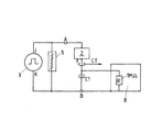
multiplier tube),部分放電PDの検出と同時刻における出力を部分放電開始電圧(PDIV)として読み出す分圧器5,光電子増倍管4で検出された部分放電PDと分圧器5で読み出された部分放電開始電圧(PDIV)とをデータとして表示するデジタルオシロスコープ8,及びデータを蓄積すると共に高電圧回路を遮断し,予め決められた所定の一定時間休止する各処理を行い,前記各処理即ちこれらの処理を予め決められた設定回数まで繰り返してデータ計測を行わせる制御装置6(PC)から構成されている。
2 ツイストペア試料(導体)
3 高電圧パルス電源
4 光電子増倍管
5 分圧器
6,7 制御装置
8 デジタルオシロスコープ
9 波形調整ユニット
10 導線
11 銅線
12 エナメル層
C1 コンデンサ
PD 部分放電
PDIV 部分放電開始電圧
LAN インターネット
Claims (10)
- 電気機器における互いに絶縁された導体間に少なくとも電圧波形と電圧上昇率が設定された繰り返し高電圧パルスを印加し,前記導体間に部分放電が発生すると,該部分放電の信号を検出装置で検出し,同時刻における分圧器の出力を部分放電開始電圧として読み出し,それと同時に高電圧回路を遮断し,予め決められた所定の一定時間休止する各処理を行い,前記各処理を予め決められた設定回数まで繰り返してデータ計測を行うことを特徴とする部分放電開始電圧計測方法。
- 前記検出装置として光電子増倍管を使用し,前記部分放電によって発生する放電光の光強度を前記光電子増倍管で検出することを特徴とする請求項1に記載の部分放電開始電圧計測方法。
- 前記検出装置として電磁波検出アンテナを使用し,前記部分放電によって発生する電磁波を前記電磁波検出アンテナで検出することを特徴とする請求項1に記載の部分放電開始電圧計測方法。
- 前記検出装置として高周波変成器を使用し,前記部分放電によって発生する放電電流を前記高周波変成器の出力波形の変化で検出することを特徴とする請求項1に記載の部分放電開始電圧計測方法。
- 前記検出装置として直列コンデンサを使用し,前記部分放電によって発生する放電電荷を前記直列コンデンサのコンデンサ波形の変化で検出することを特徴とする請求項1に記載の部分放電開始電圧計測方法。
- 前記分圧器の出力として読み出された前記部分放電開始電圧の前記データを制御装置に蓄積し,インターネットに一部の前記データを転送することを特徴とする請求項1〜5のいずれか1項に記載の部分放電開始電圧計測方法。
- 前記パルス電圧の印加から前記制御装置へのデータ蓄積までの一連の処理を,ソフトウエアを用いて設定回数を繰り返し行うことを特徴とする請求項6に記載の部分放電開始電圧計測方法。
- 前記導体間に対して前記部分放電開始電圧の計測を少なくとも複数回以上連続して行って前記電気機器の絶縁劣化評価のため前記導体間の絶縁表面上の電荷分布を判定することを特徴とする請求項1〜7のいずれか1項に記載の部分放電開始計測方法。
- 電気機器における互いに絶縁された導体間に少なくとも電圧波形と電圧上昇率を予め設定する波形調整ユニット,該波形調整ユニットで設定された前記電圧波形と前記電圧上昇率で繰り返し高電圧パルスを印加する高電圧パルス電源,前記導体間に発生した部分放電の信号を検出する検出装置,前記部分放電の検出と同時刻における分圧器の出力を部分放電開始電圧として読み出す分圧器,前記検出装置で検出された前記部分放電と前記分圧器で読み出された前記部分放電開始電圧とをデジタルデータとして取り込む装置,及び前記データを蓄積すると共に高電圧回路を遮断し,予め決められた所定の一定時間休止する各処理を行い,前記各処理を予め決められた設定回数まで繰り返してデータ計測を行わせる制御装置,から構成されていることを特徴とする部分放電開始電圧計測装置。
- 前記部分放電を検出する前記検出装置としては,前記部分放電で発生する放電光の光強度を検出する光電子増倍管,前記部分放電で発生する電磁波を検出する電磁波検出アンテナ,前記部分放電で発生する放電電流を検出する高周波変成器,又は前記部分放電で発生する放電電荷を検出する直列コンデンサであることを特徴とする請求項9に記載の部分放電開始電圧計測装置。
Priority Applications (1)
| Application Number | Priority Date | Filing Date | Title |
|---|---|---|---|
| JP2004214244A JP4378478B2 (ja) | 2004-07-22 | 2004-07-22 | 部分放電開始電圧計測方法及びその装置 |
Applications Claiming Priority (1)
| Application Number | Priority Date | Filing Date | Title |
|---|---|---|---|
| JP2004214244A JP4378478B2 (ja) | 2004-07-22 | 2004-07-22 | 部分放電開始電圧計測方法及びその装置 |
Publications (2)
| Publication Number | Publication Date |
|---|---|
| JP2006038471A JP2006038471A (ja) | 2006-02-09 |
| JP4378478B2 true JP4378478B2 (ja) | 2009-12-09 |
Family
ID=35903633
Family Applications (1)
| Application Number | Title | Priority Date | Filing Date |
|---|---|---|---|
| JP2004214244A Active JP4378478B2 (ja) | 2004-07-22 | 2004-07-22 | 部分放電開始電圧計測方法及びその装置 |
Country Status (1)
| Country | Link |
|---|---|
| JP (1) | JP4378478B2 (ja) |
Families Citing this family (13)
| Publication number | Priority date | Publication date | Assignee | Title |
|---|---|---|---|---|
| JP4726654B2 (ja) * | 2006-02-28 | 2011-07-20 | 日立オートモティブシステムズ株式会社 | インバータ駆動モータの絶縁評価方法及びその方法を利用した設計方法、検査方法、診断方法並びにそれらの装置 |
| JP2010032457A (ja) * | 2008-07-31 | 2010-02-12 | Hioki Ee Corp | 絶縁検査装置および絶縁検査方法 |
| JP2010204067A (ja) * | 2009-03-06 | 2010-09-16 | Ehime Univ | 部分放電発生回数測定装置 |
| JP5238596B2 (ja) * | 2009-04-27 | 2013-07-17 | 株式会社日本自動車部品総合研究所 | 回転電機の放電量測定装置および放電量測定方法 |
| JP5414376B2 (ja) * | 2009-06-18 | 2014-02-12 | 株式会社日立産機システム | 部分放電検査方法および回転電機 |
| JP5444185B2 (ja) * | 2010-10-15 | 2014-03-19 | 株式会社日本自動車部品総合研究所 | 部分放電測定装置及び部分放電測定方法 |
| JP2012154879A (ja) * | 2011-01-28 | 2012-08-16 | Meidensha Corp | 部分放電計測装置 |
| JP5113919B2 (ja) * | 2011-02-28 | 2013-01-09 | 日立オートモティブシステムズ株式会社 | インバータ駆動モータの検査診断方法 |
| JP2013002871A (ja) * | 2011-06-14 | 2013-01-07 | Toshiba Corp | 繰り返しインパルス電圧による部分放電計測システムおよび部分放電計測方法 |
| JP5941669B2 (ja) | 2011-12-20 | 2016-06-29 | 東芝三菱電機産業システム株式会社 | インパルス電圧発生装置 |
| JP6134101B2 (ja) * | 2012-03-14 | 2017-05-24 | 東芝三菱電機産業システム株式会社 | 繰り返しインパルス電圧による部分放電計測システムおよび部分放電計測方法 |
| CN102914732A (zh) * | 2012-10-24 | 2013-02-06 | 武汉神动汽车电子电器有限公司 | 一种浪涌冲击试验装置 |
| JP6103353B2 (ja) * | 2013-01-15 | 2017-03-29 | 国立大学法人九州工業大学 | 非接触放電試験方法及び装置 |
-
2004
- 2004-07-22 JP JP2004214244A patent/JP4378478B2/ja active Active
Also Published As
| Publication number | Publication date |
|---|---|
| JP2006038471A (ja) | 2006-02-09 |
Similar Documents
| Publication | Publication Date | Title |
|---|---|---|
| JP4378478B2 (ja) | 部分放電開始電圧計測方法及びその装置 | |
| Tozzi et al. | Monitoring off-line and on-line PD under impulsive voltage on induction motors-part 1: standard procedure | |
| Wang et al. | Characteristics of PD under square wave voltages and their influence on motor insulation endurance | |
| Gu et al. | Partial discharge detection on 320 kV VSC-HVDC XLPE cable with artificial defects under DC voltage | |
| Kimura et al. | PDIV characteristics of twisted-pair of magnet wires with repetitive impulse voltage | |
| JP4726654B2 (ja) | インバータ駆動モータの絶縁評価方法及びその方法を利用した設計方法、検査方法、診断方法並びにそれらの装置 | |
| US20050035768A1 (en) | Method and electromagnetic sensor for measuring partial discharges in windings of electrical devices | |
| Cavallini et al. | Off-line PD testing of converter-fed wire-wound motors: when IEC TS 60034-18-41 may fail? | |
| JPS5914194B2 (ja) | 回転電機の固定子巻線のア−ク事故検出方法 | |
| KR20110052612A (ko) | 전기 머신에서 베어링 전류를 측정하기 위한 방법 및 장치 | |
| Lusuardi et al. | The impact of test voltage waveform in determining the repetitive partial discharge inception voltage of type i turn/turn insulation used in inverter-fed induction motors | |
| Xiong et al. | The Ohio State University partial discharge detection platform for electric machine windings driven by PWM voltage excitation | |
| JP2010204067A (ja) | 部分放電発生回数測定装置 | |
| Wang et al. | Considering the parameters of pulse width modulation voltage to improve the signal-to-noise ratio of partial discharge tests for inverter-fed motors | |
| Wang et al. | Influence of ambient humidity on PDIV and endurance of inverter-fed motor insulation | |
| Sahlén et al. | Life-time investigation of mica-based insulation for high voltage machines subjected to converter-like voltages | |
| Cavallini et al. | Electrical aging of inverter-fed wire-wound induction motors: from quality control to end of life | |
| EP1418437A1 (en) | Method and electromagnetic sensor for measuring partial discharges in windings of electrical devices | |
| Wei et al. | Study of partial discharge behavior at flight-altitude pressures under 60 Hz and impulse voltages for samples related to aircraft motors | |
| Florkowska et al. | Effects of inverter pulses on the electrical insulation system of motors | |
| Guastavino et al. | Influence of the rise time and of the temperature on the PD inception voltage of enameled wires | |
| Stone et al. | Partial discharge testing of random wound stators during short risetime voltage surges | |
| JP2002062330A (ja) | コイルターン間絶縁健全性評価装置及び方法 | |
| JP5113919B2 (ja) | インバータ駆動モータの検査診断方法 | |
| Guo | Online diagnosis of power systems insulation condition in wind farms |
Legal Events
| Date | Code | Title | Description |
|---|---|---|---|
| A621 | Written request for application examination |
Free format text: JAPANESE INTERMEDIATE CODE: A621 Effective date: 20070117 |
|
| A977 | Report on retrieval |
Free format text: JAPANESE INTERMEDIATE CODE: A971007 Effective date: 20090306 |
|
| A131 | Notification of reasons for refusal |
Free format text: JAPANESE INTERMEDIATE CODE: A131 Effective date: 20090317 |
|
| A521 | Written amendment |
Free format text: JAPANESE INTERMEDIATE CODE: A523 Effective date: 20090518 |
|
| A131 | Notification of reasons for refusal |
Free format text: JAPANESE INTERMEDIATE CODE: A131 Effective date: 20090609 |
|
| A521 | Written amendment |
Free format text: JAPANESE INTERMEDIATE CODE: A523 Effective date: 20090730 |
|
| TRDD | Decision of grant or rejection written | ||
| A01 | Written decision to grant a patent or to grant a registration (utility model) |
Free format text: JAPANESE INTERMEDIATE CODE: A01 Effective date: 20090818 |
|
| A01 | Written decision to grant a patent or to grant a registration (utility model) |
Free format text: JAPANESE INTERMEDIATE CODE: A01 |
|
| R150 | Certificate of patent or registration of utility model |
Free format text: JAPANESE INTERMEDIATE CODE: R150 |