WO2022130929A1 - Appareil de suspension - Google Patents
Appareil de suspension Download PDFInfo
- Publication number
- WO2022130929A1 WO2022130929A1 PCT/JP2021/043220 JP2021043220W WO2022130929A1 WO 2022130929 A1 WO2022130929 A1 WO 2022130929A1 JP 2021043220 W JP2021043220 W JP 2021043220W WO 2022130929 A1 WO2022130929 A1 WO 2022130929A1
- Authority
- WO
- WIPO (PCT)
- Prior art keywords
- connecting member
- link
- metal fitting
- rotary connecting
- beam portion
- Prior art date
Links
- 239000002184 metal Substances 0.000 claims description 133
- 238000005452 bending Methods 0.000 claims description 6
- 238000004904 shortening Methods 0.000 abstract 1
- 230000002093 peripheral effect Effects 0.000 description 43
- 238000003780 insertion Methods 0.000 description 20
- 230000037431 insertion Effects 0.000 description 20
- NJPPVKZQTLUDBO-UHFFFAOYSA-N novaluron Chemical compound C1=C(Cl)C(OC(F)(F)C(OC(F)(F)F)F)=CC=C1NC(=O)NC(=O)C1=C(F)C=CC=C1F NJPPVKZQTLUDBO-UHFFFAOYSA-N 0.000 description 10
- 238000000034 method Methods 0.000 description 6
- 230000000694 effects Effects 0.000 description 2
- 230000001154 acute effect Effects 0.000 description 1
- 230000012447 hatching Effects 0.000 description 1
- 239000000725 suspension Substances 0.000 description 1
Images


Classifications
-
- B—PERFORMING OPERATIONS; TRANSPORTING
- B66—HOISTING; LIFTING; HAULING
- B66C—CRANES; LOAD-ENGAGING ELEMENTS OR DEVICES FOR CRANES, CAPSTANS, WINCHES, OR TACKLES
- B66C1/00—Load-engaging elements or devices attached to lifting or lowering gear of cranes or adapted for connection therewith for transmitting lifting forces to articles or groups of articles
- B66C1/10—Load-engaging elements or devices attached to lifting or lowering gear of cranes or adapted for connection therewith for transmitting lifting forces to articles or groups of articles by mechanical means
- B66C1/62—Load-engaging elements or devices attached to lifting or lowering gear of cranes or adapted for connection therewith for transmitting lifting forces to articles or groups of articles by mechanical means comprising article-engaging members of a shape complementary to that of the articles to be handled
- B66C1/66—Load-engaging elements or devices attached to lifting or lowering gear of cranes or adapted for connection therewith for transmitting lifting forces to articles or groups of articles by mechanical means comprising article-engaging members of a shape complementary to that of the articles to be handled for engaging holes, recesses, or abutments on articles specially provided for facilitating handling thereof
Definitions
- the present invention relates to a hanging metal fitting used when carrying out a load hanging work, a load raising work, a reversing work, and the like.
- eyebolts (hanging metal fittings) have been used as metal fittings to be attached to the load when lifting the load, raising or reversing the load, etc.
- the hanging metal fitting is used in a state where the male threaded portion is screwed into the female threaded portion of the load and tightened to the mounting surface of the load. If the direction of the load acting on the eyebolt is not correct in the above work, the screw will rotate in the loosening direction, and if the screw is used continuously in that state, the screw may fall off or the screw portion may be bent or broken, which is dangerous.
- a holding part that rotates 360 ° around the axial direction of the threaded part
- a hanging metal fitting with a shackle that is swingably supported by the holding part
- a hanging metal fitting that rotates 360 ° around the axial center of the threaded part.
- Various flexible hanging metal fittings are provided, such as a hanging metal fitting having a rotary connecting member and an oval-shaped link engaged with the rotary connecting member.
- the link attached to the rotary connecting member is attached to the rotary connecting member. It has a structure that can not only swing and move along the shape of the link. Therefore, the load may be lifted while the link is not suitable for lifting the load, and when the load is lifted, an excessive load is applied to the hanging metal fitting, which is dangerous.
- a hanging metal fitting capable of correcting the mutual state (posture) of the annular link and the rotary connecting member to a state suitable for lifting the load in the process of lifting the load is also provided (see Patent Document 1). ..
- the opening of the rotary connecting member is arranged so that the position of the center of the opening is shifted by a predetermined amount from the axial direction of the screw portion, and the width of the annular portion is set to the opening in the plan view of the hanging bracket.
- the structure is formed so that it becomes narrower in the direction of the shift.
- the rotary connecting member rotates about the axial direction of the threaded portion while the link is moved to one end side where the width of the rotary connecting member becomes narrow in the process of lifting the load.
- the mutual state of the annular link and the rotary connecting member is corrected to a state suitable for lifting the load.
- the annular link is always rotationally connected. It will move to one end side where the width of the member becomes narrower. That is, only one end side of the rotary connecting member is easily worn due to friction with the link, and the life of the hanging metal fitting itself may be shortened. Further, since the center position of the opening is arranged so as to be offset by a predetermined amount from the axis of the threaded portion, an eccentric load acts, which is not preferable.
- the present invention has been made in view of such a problem, and an object of the present invention is a structure for correcting the mutual state between an annular link to a lifting direction and a rotary connecting member in the process of lifting a load. It is an object of the present invention to provide a hanging metal fitting capable of preventing a shortened life due to wear of only one end side of a connecting member.
- one aspect of the hanging metal fitting is a hanging metal fitting that is fixed to the loading surface of the load and is used during the lifting work of the load, and rotates about the orthogonal direction of the mounting surface of the load.
- the rotary connecting member is provided with an anchor fitting having a male screw portion screwed to a female screw portion provided on the mounting surface of the load and supporting the rotary connecting member, and the rotary connecting member includes a main body portion and a main body portion. It has an arch-shaped beam portion provided above the main body portion and an opening formed by providing the beam portion on the upper portion of the main body portion, and is provided at both ends in the width direction of the beam portion.
- At least a part of at least one of the side surfaces is the middle point of the beam portion in the extending direction of the beam portion, or the extension from the middle point in the plan view of the rotary connecting member. It is characterized by having a shape protruding outward at a position deviated from the current direction by a predetermined amount.
- the side surface is formed by joining at least two planes bent outward, and the apex of the side surface is a midpoint in the extending direction of the beam portion in the plan view of the rotary connecting member. It is arranged on a straight line extending through and extending in a direction orthogonal to the extending direction of the beam portion.
- the side surface is formed by joining at least two planes bent outward, and the apex of the side surface is from the midpoint in the extending direction of the beam portion in the plan view of the rotary connecting member. , It is arranged at a position deviated by a predetermined amount on the end side of either end of the beam portion.
- the opening is provided so that the central axis of the opening is orthogonal to the rotation axis of the rotation connecting member.
- the link is formed by bending a rod member into an oval shape having two semi-arc portions and two straight portions connecting the two semi-arc portions, and the diameter of the opening is It is preferable that the diameter is larger than the diameter of the rod member and smaller than the maximum radius of the two semi-circular portions provided on the link.
- the anchor metal fitting has a metal fitting connecting portion for rotatably connecting the rotary connecting member, and the outer shape of the upper surface of the metal fitting connecting portion is larger than the outer shape of the lower surface of the main body portion.
- the structure corrects the posture of the link with respect to the anchor metal fitting in the process of lifting the load, and it is possible to prevent the life due to wear of only one end side of the rotary connecting member from being shortened.
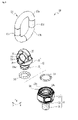
- FIG. 3 is a perspective view showing the hanging metal fitting shown in FIG. 1 in an exploded manner. It is a perspective view which shows an example of the structure of a rotary connecting member.
- FIG. 4A is a plan view illustrating the configuration of the side surface of the beam portion of the rotary connecting member
- FIG. 4B is a plan view illustrating the width of the beam portion of the rotary connecting member.
- 4 (a) is a cross-sectional view taken along the line II shown in FIG. 4 (b)
- FIG. 5 (b) is a cross-sectional view taken along the line II-II shown in FIG. 5 (a).
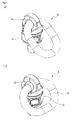
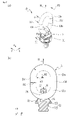
- FIG. 5A is a perspective view showing an example of a hanging metal fitting in which the link is held in a state where the semi-arc portion of the link is inserted through the opening of the rotary connecting member
- FIG. 5B is a straight line portion of the link.
- Is a perspective view showing an example of a hanging metal fitting in which a link is held while being inserted through an opening of a rotary connecting member
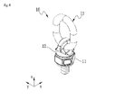
- FIG. 7 (a) is a perspective view showing an example of a hanging metal fitting when a force H in the z direction is applied to the link in a state where the semi-arc portion of the link is inserted through the opening of the rotary connecting member.
- FIG. 9 (a) is a perspective view showing an example of a hanging metal fitting when a force J in the x direction is applied to the link in a state where the straight portion of the link is inserted through the opening of the rotary connecting member, FIG. 9 (b). ) Is a cross-sectional view showing the state of the link and the rotary connecting member of the hanging metal fitting shown in FIG. 9A, and FIG. 9C is a plan view of the hanging metal fitting shown in FIG. 9A.
- FIG. 9 (a) is a cross-sectional view showing a state of a link of a hanging metal fitting and a rotary connecting member when a force K is applied to the link diagonally upward.
- FIG. 12 (a) is a plan view illustrating the configuration of another form of the side surface of the beam portion of the rotary connecting member
- FIG. 12 (b) is a plan view illustrating the width of the beam portion of the rotary connecting member.
- 13 (a) is a sectional view taken along line III-III shown in FIG. 12 (b)
- FIG. 5 (b) is a sectional view taken along line IV-IV shown in FIG. 13 (a).
- FIG. 14 (a) is a plan view of the hanging metal fitting
- FIG. 14 (b) is a cross-sectional view showing the state of the link and the rotary connecting member of the hanging metal fitting shown in FIG. 14 (a).
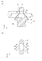
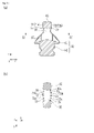
- 15 (a) is a perspective view showing another embodiment of the hanging metal fitting
- FIG. 15 (b) is a side view of the hanging metal fitting shown in FIG. 15 (a).
- the width of the arch-shaped beam portion 37 which will be described later, is the x direction
- the direction connecting both ends of the arch-shaped beam portion 37 is the y direction
- the thickness (height) direction of the beam portion 37 of the above is defined as the z direction.
- the hanging metal fitting 10 described in the present embodiment is a kind of so-called hanging metal fitting, and is fixed to the mounting surface of the load and used for lifting work, raising work, reversing work, and the like.
- the hanging metal fitting 10 has an anchor metal fitting 11, a rotary connecting member 12, and a link 13.
- the anchor metal fitting 11 is a portion attached to a load (not shown), and in the present embodiment, the anchor metal fitting 11 is provided in a shape in which a recess is formed in the head of a hexagon bolt.
- the anchor metal fitting 11 has a male screw portion 21, an anchor seat portion 22, and a metal fitting connecting portion 23.
- the male screw portion 21 extends from the lower surface of the metal fitting connecting portion 23 in a direction orthogonal to the lower surface (z direction) in a direction opposite to the insertion space 24 of the metal fitting connecting portion 23, which will be described later, so as to coincide with the axis.
- the male screw portion 21 is a shaft-shaped portion in which a male screw is formed on the outer peripheral surface.
- the male screw portion 21 is screwed into the female screw provided in the mounting hole of the load. As a result, the anchor fitting 11 is fixed to the load.
- the anchor seat portion 22 is integrated with the metal fitting connecting portion 23 on the lower end side of the metal fitting connecting portion 23.
- the anchor seat portion 22 comes into contact with the load mounting surface when the hanging metal fitting 10 is fixed to the load mounting surface (not shown), and prevents a gap from being generated between the anchor metal fitting 11 and the load.
- the anchor seat portion 22 may be provided at the lower end of the metal fitting connecting portion 23 in the shape of a circular ring around the male screw portion 21, or may be provided in the shape of a disk.
- the metal fitting connecting portion 23 is a member corresponding to the head of a bolt that is easy to operate with a tool. That is, the metal fitting connecting portion 23 has a shape (for example, a hexagonal column shape) that can be fitted into a tool such as a spanner. Therefore, by fitting the metal fitting connecting portion 23 into the tool, the male screw portion 21 can be easily screwed into the female screw of the load, and the workability when tightening the anchor metal fitting 11 is improved.
- the metal fitting connecting portion 23 is a portion connected to the rotary connecting member 12.
- the metal fitting connecting portion 23 has an insertion space 24 having an open upper surface.
- the rotation shaft portion 33 of the rotation connection member 12 is inserted into the insertion space 24.
- a recess 24a having a substantially semicircular cross section is formed over the entire circumference.
- the recess 24a faces a donut-shaped passage (not shown) facing the recess 33a provided in the rotary shaft portion 33 of the rotary connecting member 12 when the rotary shaft portion 33 of the rotary connecting member 12 is inserted into the insertion space 24.
- a plurality of bearing balls 30 are arranged in the donut-shaped passage. By arranging the plurality of bearing balls 30 in the passage, the rotary connecting member 12 can be smoothly rotated with respect to the metal fitting connecting portion 23.
- the plurality of bearing balls 30 have female screw holes provided in the metal fitting connecting portion 23 in a state where the rotating shaft portion 33 of the rotating connecting member 12 is inserted in the insertion space 24 of the anchor metal fitting 11 (not shown). ) Is inserted into the donut-shaped passage.
- the female screw hole is sealed with a screw rod or the like having a hexagonal hole. As a result, it is possible to prevent the bearing ball 30 from deviating from the female screw hole.
- the metal fitting connecting portion 23 has a stepped portion 24b connected to the insertion space 24 at the upper end portion of the insertion space 24.
- the step portion 24b arranges a plurality of bearing balls 31 over the entire circumference.
- the rotary connecting member 12 is a member to which the link 13 is engaged.
- the rotary connecting member 12 is rotatable in the E1 direction or the E2 direction (circumferential direction of the rotation shaft portion 33) in FIG. 1 with respect to the anchor metal fitting 11.
- the rotary connecting member 12 has a main body portion 32 and a rotary shaft portion 33.
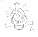
- the main body portion 32 straddles two raised portions 35, 36 and two raised portions 35, 36 provided on the upper surface of the disk-shaped main body portion 32 at intervals of 180 °. It has an arch-shaped beam portion 37 arranged in a row.
- the beam portion 37 and the two raised portions 35 and 36 form an annular portion on the upper surface of the main body portion 32. Further, since the annular portion is formed by the beam portion 37 and the two raised portions 35 and 36, the main body portion 32 has an opening 39 surrounded by these.
- the rotary connecting member 12 is subjected to R chamfering on the boundary portion between two consecutive surfaces.
- a recess (groove) 38 is provided between the two raised portions 35 and 36 in a direction orthogonal to the extending direction of the beam portion 37.
- the recess 38 is provided so as to be connected to the opening 39 provided below the beam portion 37.
- the raised portions 35 and 36 each have an upper surface which is an uphill slope toward the side surfaces 41 and 42 of the beam portion 37.
- the beam portion 37 has side surfaces 41 and 42 at both ends in the x direction in FIG. 4A.
- One side surface 41 has a shape in which two planes 41a and 41b are bent and joined so as to be convex toward the outer peripheral edge (outer side) of the main body portion 32 in a plan view of the hanging metal fitting 10. .
- the other side surface 42 of the beam portion 37 is folded so that the two planes 42a and 42b are convex toward the outer peripheral edge (outer side) of the main body portion 32 in the plan view of the hanging metal fitting 10. It is a curved and joined shape.
- the apex T1 of the side surface 41 and the apex T2 of the side surface 42 are located at the midpoint in the extending direction of the beam portion 37 (in the y direction in FIG. 4A). That is, the apex T1 of the side surface 41 and the apex T2 of the side surface 42 are orthogonal to the extending direction of the beam portion 37 and are on the plane PL including the rotation axis (axis center) C1 of the rotation axis portion 33 of the rotation connecting member 12. Be placed. In this form, the side surface 41 and the side surface 42 of the beam portion 37 are bent and joined so that the two planes are convex toward the outer peripheral edge (outer side) of the main body portion 32.
- the above-mentioned angle ⁇ 1 and angle ⁇ 2 are set as follows. For example, if the above-mentioned angle ⁇ 1 and angle ⁇ 2 are increased, the amount of movement of the link 13 becomes smaller when the link 13 moves to either end of both ends of the beam portion 37 in the extending direction. The link 13 easily bites into the gap formed between the raised portion (either the raised portion 35 or the raised portion 36) of the rotary connecting member 12 located on the side where the link 13 moves and the beam portion 37. As a result, the rotary connecting member 12 may not rotate until the posture of the link 13 with respect to the rotary connecting member 12 is stable (see FIG. 10 described later), and may stop rotating in the middle of the rotation.
- the posture of the link 13 with respect to the rotary connecting member 12 is unstable, and when a force different from the force acting in the direction of suspending the load acts on the hanging metal fitting 10, the biting of the link 13 into the gap is eliminated. It is dangerous because the rotary connecting member 12 rotates until the posture of the link 13 with respect to the rotary connecting member 12 is stable.
- the angle ⁇ 1 and the angle ⁇ 2 are preferably in the range of, for example, 5 to 25 °, for example, in the range of 10 to 15 °, in view of ensuring the force acting when moving to one end. It is preferable to have.
- the beam portion 37 is R chamfered. Therefore, as shown in FIGS. 5A and 5B, a curved surface 45 is formed between the flat surface 41a of the beam portion 37 and the inner peripheral surface 39a of the opening portion 39. Further, a curved surface 46 is formed between the flat surface 41b of the beam portion 37 and the inner peripheral surface 39a of the opening portion 39. Between these curved surfaces 45 and 46, a curved surface 47 connected to these curved surfaces 45 and 46 is provided.
- a curved surface 48 is formed between the flat surface 42a of the beam portion 37 and the inner peripheral surface (in other words, the lower surface of the beam portion 37) 39a of the opening 39. Further, a curved surface 49 is formed between the flat surface 42b of the beam portion 37 and the inner peripheral surface 39a of the opening portion 39. Between these curved surfaces 48 and 49, a curved surface 50 connected to these curved surfaces 48 and 49 is provided.
- the opening 39 penetrates and extends in the extending direction of the beam portion 37 (y direction in FIG. 3) and the direction orthogonal to the axis C1 of the rotating shaft portion 33 (x direction in FIG. 5A). is doing.
- the opening 39 has a circular opening cross section, and its central axis is the axis (axis along the z direction) of the rotation shaft portion 33 which is the rotation center of the rotation connecting member 12. It is provided on the main body 32 so as to be orthogonal to each other.
- the inner peripheral surface 39a of the opening 39 is a curved surface (arc surface) in which the central portion of the opening 39 in the axial direction projects toward the center of the opening 39.
- the radius R of the protruding curved surface (arc surface) 39a is, for example, the same as the minimum bending radius R1 of the semi-arc portions 13a and 13b of the link 13.
- the minimum diameter D1 (see FIG. 5A) at the opening 39 is larger than, for example, the diameter D2 of the rod member constituting the link 13 (see FIG. 7B), and is about 1 of the diameter D2. It is set smaller than .5 times.
- the minimum value D1 of the diameter at the opening 39 may be the maximum bending radius R2 or less of the semicircular arc portions 13a and 13b of the link 13.
- the rotary connecting member 12 shows a cross section, but in order to eliminate the complexity in the explanation of the figure, the description of the hatching showing the cross section is omitted.
- the radius R of the inner peripheral surface 39a is the same as the minimum radius of the semicircular arc portions 13a and 13b of the link 13, for example, but the radius of the inner peripheral surface 39a is the minimum of the semicircular arc portions 13a and 13b of the link 13, for example. It may be smaller than the radius R1.
- the rotary shaft portion 33 provided on the rotary connecting member 12 extends in the vertical direction (-z direction in FIG. 4) from the lower part of the main body portion 32.
- the rotating shaft portion 33 is pivotally supported by the anchor fitting 11 by being inserted into the insertion space 24 of the fitting connecting portion 23 of the anchor fitting 11 described above.
- the rotating shaft portion 33 has a recess 33a having an arcuate cross section on the outer peripheral surface.
- the link 13 is engaged with a crane hook, a shackle connected to the crane hook, or the like when, for example, a load lifting operation, a raising operation, or a reversing operation is performed.
- the link 13 is an oval-shaped member having, for example, two semi-arc portions 13a and 13b and two straight portions 13c and 13d connecting these semi-arc portions 13a and 13b.
- the diameters of the semi-arc portion 13a and the semi-arc portion 13b are the same. Therefore, the two straight portions 13c and the straight portions 13d are parallel.
- the shape of the link 13 may be endless, and is not limited to an oval shape.
- the link 13 is not limited to the metal ring, and may be a wire rope ring, a stud link, or the like.
- the link 13 is held in a state of being connected to the rotary connecting member 12.
- the link 13 rotates in the F1 direction or the F2 direction in FIG. 1 with the portion inserted through the opening 39 of the rotary connecting member 12 as the center. Further, the link 13 rotates in the F3 or F4 direction on a plane (xz plane in FIG. 1) including a line connecting the centers in a cross section orthogonal to the extending direction of the link 13.
- FIGS. 6 (a) and 6 (b) show an example, and the posture of the link 13 when the hanging metal fitting 10 is not used or when no force is applied to the link 13 is shown in FIG. 6 (a) and FIG. 6 (b) are not limited to this. Further, FIGS. 6 (a) and 6 (b) illustrate the case where the hanging metal fitting 10 is attached to the upper surface of the load, but even when the hanging metal fitting 10 is attached to the side surface of the load, the link is formed.
- Reference numeral 13 is a state in which either the semi-arc portion 13a or the semi-arc portion 13b of the link 13 is inserted through the opening 39 of the rotary connecting member 12, and the link 13 is rotated by a predetermined angle in the F2 direction in FIG. Needless to say, it is held in a state where either the straight portion 13c or the straight portion 13d is inserted into the opening 39 of the rotary connecting member 12 and rotated by a predetermined amount in the F2 direction in FIG.
- the semi-arc portion 13b of the link 13 is inserted through the opening 39 of the rotary connecting member 12, and the extending directions of the straight portions 13c and 13d of the link 13 are z.
- a force H in the z direction in FIG. 7 acts on the semi-arc portion 13a of the link 13 will be described.
- the link 13 When a force H in the z direction in FIG. 7 acts on the link 13, as shown in FIG. 7B, the link 13 is a peripheral surface portion of the inner peripheral surface 39a of the opening 39 that functions as the lower surface of the beam portion 37.
- the rotary connecting member 12 is pulled upward.
- the inner peripheral surface 39a of the opening 39 is the same as the minimum bending radius R1 of the semicircular arc portions 13a and 13b of the link 13. Therefore, the link 13 is in a state where the semi-arc portion 13b is in line contact with the portion of the inner peripheral surface 39a of the opening 39, which is located on the lower surface of the beam portion 37. In this state, the posture of the link 13 with respect to the rotary connecting member 12 is stable.
- FIG. 8 shows a state after the rotational force F1 acts on the link 13 and the link 13 and the rotary connecting member 12 rotate by 90 °.
- the linear portion 13d of the link 13 is inserted through the opening 39 of the rotary connecting member 12, in other words, the longitudinal direction of the link 13 is the rotary shaft of the rotary connecting member 12.
- a force J in the x direction in FIG. 9C may act on the semicircular arc portion 13a of the link 13.
- the semi-arc portion 13b of the link 13 abuts on the curved surface 47 provided on the lower surface of the beam portion 37 and the inner peripheral surface 39a of the opening 39 (points P1 and P2 in FIG. 9B).
- the link 13 since the link 13 is in contact with the rotary connecting member 12 at two points P1 and P2, the link 13 is in an unstable posture.
- the rotary connecting member 12 rotates in the E1 direction, and the position where the semi-arc portion 13b of the link 13 abuts on the curved surface 45 moves in the outer peripheral direction of the rotary connecting member 12.
- the link 13 rotates in the S1 direction.
- the rotary connecting member 12 also rotates in the E1 direction.
- the rotary connecting member 12 is rotated by, for example, 90 °, the link 13 is in line contact with the inner peripheral surface 39a of the opening 39 of the rotary connecting member 12.
- the posture of the link 13 with respect to the rotary connecting member 12 is stabilized, and the rotation of the rotary connecting member 12 and the link 13 is stopped.
- the link 13 rotates in the S2 direction. Also in this case, by rotating the link 13 in the S2 direction, the rotary connecting member 12 also rotates in the E2 direction. Then, when the rotary connecting member 12 is rotated by, for example, 90 °, the link 13 is in line contact with the inner peripheral surface 39a of the opening 39 of the rotary connecting member 12. At this time, the posture of the link 13 with respect to the rotary connecting member 12 is stabilized, and the rotation of the rotary connecting member 12 and the rotation of the link 13 are stopped.
- the link 13 since the force K acts on the link 13, the link 13 is in a posture in which the semi-arc portion 13a is diagonally 45 ° above the semi-arc portion 13b. In this state, the semi-arc portion 13a of the link 13 and the curved surface 47 are in contact with each other (indicating the position where the point P1 abuts), and the posture of the link 13 with respect to the rotary connecting member 12 is also unstable. It is in a state.
- the link 13 has a state in which the semi-arc portion 13a of the link 13 and the curved surface 47 are in contact with each other, a state in which the semi-arc portion 13a of the link 13 and the curved surface 45 are in contact with each other, or a semi-arc portion of the link 13. It is in one of the states where the 13a and the curved surface 46 are in contact with each other.
- the rotary connecting member 12 rotates in the E1 direction or the E2 direction, and the rotary connecting member 12 is rotated.
- the hanging metal fitting 10 of the present embodiment is a hanging metal fitting 10 fixed to the loading surface of the load and used at the time of lifting the load, and is a rotary connection that rotates about the orthogonal direction of the mounting surface of the load.
- a member 12 and a link 13 which is connected to the rotary connecting member 12 and is locked by a hanging member during a load lifting operation are provided, and the rotary connecting member 12 is provided above the main body portion 32 and the main body portion 32. It has a beam portion 37 to be formed, an opening 39 provided between the beam portion 37 and the main body portion 32, and an opening 39 through which a link 13 connected to the rotary connecting member 12 is inserted, and the width of the central portion of the beam portion 37. However, it is configured to be wider than the width of both ends.
- the link 13 in a posture in which the link 13 is located in a direction in which the longitudinal direction of the link 13 is orthogonal to the rotation axis direction of the rotation connecting member 12, the link 13 has a point P1. And at the point P2, it is in contact with the rotary connecting member 12. If the positional relationship between the link 13 and the rotary connecting member 12 does not change in this state, the link 13 will be located in a very unstable state.
- the widths of the central portions of the side surfaces 41 and 42 of the beam portion 37 in the extending direction of the beam portion 37 in the plan view of the rotary connecting member 12 are set. At least two planes are combined and bent outward so that they are wider than the width of both ends. Therefore, when a force is applied to the link 13 engaged with the rotary connecting member 12, the link 13 moves toward either end of the beam portion 37 in the longitudinal direction, and the rotary connecting member 12 moves. To rotate. By this rotation, the posture of the link 13 with respect to the rotary connecting member 12 can be changed so that the longitudinal direction of the link 13 is parallel to the extending direction of the beam portion 37 of the rotary connecting member 12 (see FIG. 10).
- the moving direction of the link 13 is not limited to one direction depending on the direction of the force acting on the link 13. That is, in FIG. 4, the link 13 can move in two directions, the y direction and the ⁇ y direction, depending on the force acting on the link 13. As a result, the degree of wear of the link 13 and the beam portion 37 becomes uniform in the extending direction of the beam portion 37, and the life of the hanging metal fitting 10 itself can be extended.
- the opening 39 is provided so that the central axis of the opening 39 is orthogonal to the rotation axis of the rotation connecting member 12.
- the opening 39 is provided so that the central axis of the opening 39 is orthogonal to the rotation axis of the rotation connecting member 12, the opening is provided so that the central axis of the opening 39 is not orthogonal to the rotation axis of the rotation connection member 12. Compared with the case where 39 is provided, the load acting on the link 13 can be reduced.
- the link 13 is an elliptical rod member having two semicircular arc portions 13a and 13b and two straight straight portions 13c and 13d connecting these two semicircular arc portions 13a and 13b, and has an opening.
- the diameter of 39 is larger than the diameter of the rod member and smaller than the maximum radius of the semicircular arc portions 13a and 13b of the link 13.
- It has an anchor metal fitting 11 that pivotally supports the rotary connecting member 12 and has a male screw portion 21 that is screwed into a female screw portion provided on the mounting surface of the load.
- the male screw portion 21 is screwed into the female screw hole of the load to fix the anchor metal fitting 11 to the load, and the anchor metal fitting 11 is used as a reference for rotational connection according to the direction of the force applied to the link 13.
- the member 12 can be freely rotated. Further, when the beam portion 37 of the rotary connecting member 12 is worn, it is sufficient to replace only the rotary connecting member 12 and the link 13 engaged with the rotary connecting member 12 instead of replacing the entire hanging metal fitting 10.
- a link having two semicircular arc portions and two straight line portions connecting these semicircular arc portions is taken as an example, but a link having a shape in which two arcs having different sizes are combined or a straight line is used. It may be a link having a circular shape or an elliptical shape without a portion. Further, two straight lines extending in one direction and two straight lines extending in a direction orthogonal to one direction are arranged in a frame shape, and these straight lines are connected by arcs arranged at four corners. It may also be a shaped link.
- the shape may be such that the link and the rotary connecting member can be engaged with each other with an appropriate degree of freedom by inserting a part of the closed link into the opening 39 of the rotary connecting member 12.
- the diameter of the opening 39 of the rotary connecting member 12 is larger than the diameter of the rod member constituting the link and smaller than the maximum outer diameter of the arc portion of the link. It is possible to have the same effect as the embodiment.
- the side surfaces 41 and 42 of the beam portion 37 of the rotary connecting member are configured so that the width of the midpoint in the extending direction of the beam portion is wider than the width of both ends.
- the side surfaces 41 and 42 of the beam portion 37 are side surfaces that are bent outward by combining at least two planes.
- a curved surface may be formed so that the width of the central portion of the beam portion is wider than the width of both end portions.
- two or more curved surfaces may be combined and configured. In this case, either a concave curved surface or a convex curved surface can be used as the two curved surfaces.
- the boundary between the two curved surfaces is preferably linear as much as possible.
- the positions where the two planes 41a and 41b constituting one side surface 41 of the beam portion 37 are bent and the positions where the two planes 42a and 42b constituting the other side surface 42 are bent that is, The positions of the vertices of the side surfaces 41 and 42 are the midpoints in the extending direction of the beam portion 37 (in the y direction in FIG. 4A). Therefore, as shown in FIG. 9C, the linear portion 13d of the link 13 is inserted into the opening 39 of the rotary connecting member 12, in other words, the longitudinal direction of the link 13 is the rotary shaft of the rotary connecting member 12.
- the semi-arc portion 13b of the link 13 is a curved surface 47 provided on the lower surface of the beam portion 37. And may be stable in a state of being in contact with the inner peripheral surface 39a of the opening 39 (points P1 and P2 in FIG. 9B).
- the posture of the link 13 with respect to the rotary connecting member 12 is stable, but when the load is lifted, an excessive load is applied to the hanging metal fitting 10, which is dangerous.
- the vertices of the two side surfaces of the beam portion of the rotary connecting member can be arranged at a position shifted from the midpoint instead of the midpoint in the extending direction of the beam portion.
- the link configuration will be described with the same reference numerals as those described above.
- the rotary connecting member 60 has a main body portion 61 and a rotary shaft portion 62.
- the main body portion 61 straddles two raised portions 63, 64 and two raised portions 63, 64 provided on the upper surface of the disk-shaped main body portion 61 at intervals of 180 °. It has an arch-shaped beam portion 65 arranged in a row.
- the main body portion 61 has an opening 66 surrounded by these.
- a recess (groove portion) 67 is provided between the two raised portions 63 and 64 in a direction orthogonal to the extending direction of the beam portion 65.
- the recess 67 is provided so as to be connected to the opening 66 provided below the beam portion 65.
- the beam portion 65 has two side surfaces 71 and 72.
- One side surface 71 has a shape in which two planes 71a and 71b are bent and joined so as to be convex toward the outer peripheral edge of the main body portion 61 in a top view of the rotary connecting member 60.
- the position where the two planes 71a and 71b constituting the side surface 71 bend, in other words, the position of the apex of the side surface 71 is the midpoint in the extending direction of the beam portion 65 (that is, the axial center C2 of the rotary connecting member 60). Therefore, the position is shifted by a distance L4 in the-y direction in FIG. 12 (a).
- the other side surface 72 has a shape in which two planes 72a and 72b are bent and joined so as to be convex toward the outer peripheral edge of the main body 61 in the top view of the rotary connecting member 60.
- the position where the two planes 72a and 72b constituting the other side surface 72 bend is set to the midpoint in the extending direction of the beam portion 65 (that is, the axial center of the rotary connecting member 60).
- the position is shifted from C2) by a distance L4 in the y direction in FIG. 12 (a).
- the distance L4 is set in the range of 1/10 to 1/4 of the diameter of the link 13 locked to the rotary connecting member 60. In this case, as shown in FIG.
- the angle ⁇ 3 formed by the plane 71a and the plane 72a and the angle ⁇ 4 formed by the plane 71b and the plane 72b are the same, but the details are as follows. Is set to.
- the amount of movement of the link 13 becomes smaller when the link 13 moves to either end of both ends of the beam portion 37 in the extending direction.
- the link 13 easily bites into the gap formed between the raised portion (either the raised portion 63 or the raised portion 64) of the rotary connecting member 60 located on the side where the link 13 moves and the beam portion 65.
- the rotary connecting member 12 may not rotate until the posture of the link 13 with respect to the rotary connecting member 12 is stable (see FIG. 10 described later), and may stop rotating in the middle of the rotation.
- the angle ⁇ 3 and the angle ⁇ 4 are the amount of movement of the link 13 when the link 13 moves to either end of both ends in the extending direction of the beam portion 65, and the link 13 extends the beam portion 65.
- the angle ⁇ 3 and the angle ⁇ 4 are preferably in the range of, for example, 5 to 25 °, for example, in view of ensuring the force acting when moving to either end of both ends in the current direction. It is preferably in the range of 10 to 15 °.
- the beam portion 65 is chamfered. Therefore, as shown in FIGS. 13A and 13B, a curved surface 75 is formed between the plane 71a of the beam portion 65 and the inner peripheral surface 66a of the opening 66. Further, a curved surface 76 is formed between the flat surface 71b of the beam portion 65 and the inner peripheral surface 66a of the opening portion 66. Between these curved surfaces 75 and 76, a curved surface 77 connected to these curved surfaces 75 and 76 is provided.
- a curved surface 78 is formed between the flat surface 72a of the beam portion 65 and the inner peripheral surface 66a of the opening 66. Further, a curved surface 79 is formed between the flat surface 72b of the beam portion 65 and the inner peripheral surface 66a of the opening portion 66. Between these curved surfaces 78 and 79, a curved surface 80 connected to these curved surfaces 78 and 79 is provided.
- the semi-arc portion 13b of the link 13 is inserted into the opening 66 of the rotary connecting member 60, and the longitudinal direction of the link 13 is the rotary connecting member 60.
- a force J in the x-direction in FIG. 14 (a) acts on the semi-circular arc portion 13a of the link 13 in a state orthogonal to the extending direction of the beam portion 65 and the rotation axis direction of the rotary connecting member 60, the link 13
- the inner peripheral surface of the semi-arc portion 13a is abutted on the curved surface 75 between the side surface 71 of the beam portion 65 and the inner peripheral surface 66a of the opening 66, that is, at the point P3 shown in FIG. 14 (b).
- the outer peripheral surface of the semi-arc portion 13b of the link 13 is held in contact with the inner peripheral surface 66a of the opening 66 of the rotary connecting member 60 at the point P4 shown in FIG. 14 (b).
- the side surface 71 of the beam portion 65 has a apex at a position shifted by a distance L4 in the middle ⁇ y direction of FIG. 12A from the midpoint in the extending direction of the beam portion 65.
- the side surface 72 of the beam portion 65 has a apex at a position shifted by a distance L4 in the y direction in FIG. 12A from the midpoint in the extending direction of the beam portion 65. Therefore, when the force J in the x direction in FIG. 14A acts on the semicircular arc portion 13a of the link 13, the link 13 is in contact with the rotary connecting member 60 at two points P3 and P4.
- the hanging metal fitting 10 described above has a structure in which a crane hook, a wire rope, a shackle connected to a crane hook, or the like is engaged with a link 13 that engages with a beam portion 37 of a rotary connecting member 12.
- the link 13 may be a hanging metal fitting that is not engaged with the beam portion 37 of the rotary connecting member 12.
- the hook of the crane, the wire rope, and the shackle connected to the hook of the crane directly engage with the beam portion 37 of the rotary connecting member 12.
- the link 13 may be a hanging metal fitting not engaged with the beam portion 65 of the rotary connecting member 60 in the same manner.
- the rotary shaft portion 33 provided in the rotary connecting member 12 is inserted into the insertion space 24 of the metal fitting connecting portion 23 of the anchor metal fitting 11, so that the rotary connecting member 12 can be attached to the anchor metal fitting 11. It is held rotatably.
- an insertion hole is provided in the rotary connecting member, a rotary shaft portion is provided on the upper surface of the pedestal portion of the anchor metal fitting, and the rotary shaft portion of the anchor metal fitting is inserted into the insertion hole of the rotary connection member.
- the rotary connecting member may be held rotatably with respect to the anchor fitting.
- the hanging metal fitting 81 has a rotary connecting member 82 and an anchor metal fitting 83.
- the rotary connecting member 82 has a main body portion 85 and an arch-shaped beam portion 86 provided above the main body portion 85, and both ends of the beam portion 86 in the extending direction are joined to the main body portion 85.
- the opening 87 is formed between the main body portion 85 and the beam portion 86.
- the portion where both ends of the beam portion 86 in the extending direction and the main body portion 85 are joined is the central axis of the anchor fitting 83 (details).
- the main body portion 85 is provided with an insertion hole 88 from the upper surface to the lower surface, and the rotation shaft portion 95 described later is inserted through the main body portion 85.
- the outer shape of the lower surface of the main body 85 is, for example, a circular shape.
- the anchor metal fitting 83 has a rotary connecting portion 91 and a male screw portion 92 extending from the rotary connecting portion 91.
- the rotary connecting portion 91 of the anchor fitting 83 has a hexagonal pedestal portion 94 and a rotating shaft portion 95 that protrudes upward from the upper surface of the pedestal portion 94 and is inserted into the insertion hole 88 of the rotary connecting member 82.
- recesses are provided in the inner peripheral surface facing the insertion hole 88 of the rotary connecting member 82 and the outer peripheral surface of the rotary shaft portion 95, respectively, and the rotary shaft portion 95 is provided in the insertion hole 88 of the rotary connecting member 82. When inserted, these recesses form a donut-shaped space.
- the rotary connecting member 82 is provided with a screw hole (not shown) formed toward the inner peripheral surface facing the insertion hole 88 described above, and a plurality of bearings are provided in the space through the screw hole (not shown). Insert the sphere. As a result, the rotary connecting member 82 is rotatably connected to the anchor fitting 83.
- the screw holes are sealed with hexagonal screws 89.
- the rotating shaft portion 95 is provided with a hexagonal hole 95a on the upper surface of the rotating shaft portion 95.
- a hexagon wrench (not shown) is inserted into the hexagonal hole 95a, and by rotating the hexagon wrench around the central axis C3 of the male screw portion 92, the anchor metal fitting 83 can be fastened or loosened to the load. ..
- the outer shape of the lower surface of the main body 85 of the rotary connecting member 82 is circular.
- the pedestal portion 94 of the anchor metal fitting 83 has a hexagonal column shape.
- the outer shape of the upper surface of the pedestal portion 94 is larger than the outer shape of the lower surface of the main body portion 85. That is, assuming that the diameter of the lower surface of the main body 85 is D3 and the minimum width of the pedestal portion 94 is W1, the minimum width W1 of the pedestal portion 94 is larger than the diameter D3 of the lower surface of the main body 85.
- the central axis of the anchor metal fitting 83 (specifically, the central axis of the male screw portion 92 of the anchor metal fitting 83). It is curved toward C3). Therefore, when the operator manually fastens the hanging metal fitting 81 to the load, the pedestal portion 94 can be easily grasped. Further, it is easy for the operator to tighten the male screw portion 92 of the anchor metal fitting 83 to the female screw portion of the load to some extent or rotate the anchor metal fitting 83 loosened to some extent to remove it from the load while the operator grasps the pedestal portion 94 by hand. Become. Further, since the pedestal portion 94 can be easily inserted into the mouth portion (diameter portion) of the spanner, the work of fastening the hanging metal fitting to the load and the work of removing the hanging metal fitting from the load can be easily performed.
- the extending direction of the ridge line provided between the two planes 41a and 41b constituting the side surface 41 of the beam portion 37 is, for example, in the z direction in FIG.
- the planes 41a and 41b are bent so as to be parallel to each other, and the side surface 41 of the beam portion 37 has a shape in which the midpoint in the extending direction of the beam portion 37 is projected outward.
- the extending direction of the ridge line does not have to be parallel to the z direction in FIG. 1, for example, the extending direction of the ridge line is included in either the yz plane or the xz plane, and is in the z direction in FIG.
- the side surface 41 may protrude outward at a midpoint in the extending direction of the beam portion 37 or at a position deviated by a predetermined amount from the midpoint.
- the side surface 42 of the beam portion 37 may have the same configuration as the side surface 41 of the beam portion 37, or may have a different configuration.
Landscapes
- Engineering & Computer Science (AREA)
- Mechanical Engineering (AREA)
- Load-Engaging Elements For Cranes (AREA)
- Hooks, Suction Cups, And Attachment By Adhesive Means (AREA)
Abstract
Priority Applications (4)
| Application Number | Priority Date | Filing Date | Title |
|---|---|---|---|
| JP2022569821A JP7432289B2 (ja) | 2020-12-15 | 2021-11-25 | 吊り金具 |
| CN202180079036.1A CN116490453A (zh) | 2020-12-15 | 2021-11-25 | 吊具 |
| DE112021006495.9T DE112021006495T5 (de) | 2020-12-15 | 2021-11-25 | Aufhänger |
| US18/265,973 US20240034598A1 (en) | 2020-12-15 | 2021-11-25 | Hanging fitting |
Applications Claiming Priority (2)
| Application Number | Priority Date | Filing Date | Title |
|---|---|---|---|
| JP2020-207773 | 2020-12-15 | ||
| JP2020207773 | 2020-12-15 |
Publications (1)
| Publication Number | Publication Date |
|---|---|
| WO2022130929A1 true WO2022130929A1 (fr) | 2022-06-23 |
Family
ID=82059032
Family Applications (1)
| Application Number | Title | Priority Date | Filing Date |
|---|---|---|---|
| PCT/JP2021/043220 WO2022130929A1 (fr) | 2020-12-15 | 2021-11-25 | Appareil de suspension |
Country Status (6)
| Country | Link |
|---|---|
| US (1) | US20240034598A1 (fr) |
| JP (1) | JP7432289B2 (fr) |
| CN (1) | CN116490453A (fr) |
| DE (1) | DE112021006495T5 (fr) |
| TW (1) | TW202243987A (fr) |
| WO (1) | WO2022130929A1 (fr) |
Cited By (1)
| Publication number | Priority date | Publication date | Assignee | Title |
|---|---|---|---|---|
| USD1003703S1 (en) * | 2021-06-29 | 2023-11-07 | Kito Corporation | Lifting clamp |
Citations (5)
| Publication number | Priority date | Publication date | Assignee | Title |
|---|---|---|---|---|
| JPS59186882A (ja) * | 1983-04-08 | 1984-10-23 | 株式会社キト− | 保護キャップ付き吊り具 |
| JPH1025087A (ja) * | 1996-07-08 | 1998-01-27 | Onoda:Kk | アンカーボルト吊具及びその製造方法 |
| JP2007162868A (ja) * | 2005-12-15 | 2007-06-28 | Martec Kk | 旋回吊持具ユニット |
| EP3141516A1 (fr) * | 2015-09-08 | 2017-03-15 | J.D. Theile GmbH & Co. KG | Systeme d'etayage d'un point de butee |
| GB2564114A (en) * | 2017-07-03 | 2019-01-09 | Stanton Bonna Concrete Ltd | Release mechanism |
Family Cites Families (1)
| Publication number | Priority date | Publication date | Assignee | Title |
|---|---|---|---|---|
| DE102012107733B4 (de) | 2012-08-22 | 2018-12-06 | Thiele Gmbh & Co. Kg | Anschlagpunkt |
-
2021
- 2021-11-25 WO PCT/JP2021/043220 patent/WO2022130929A1/fr active Application Filing
- 2021-11-25 CN CN202180079036.1A patent/CN116490453A/zh active Pending
- 2021-11-25 US US18/265,973 patent/US20240034598A1/en active Pending
- 2021-11-25 JP JP2022569821A patent/JP7432289B2/ja active Active
- 2021-11-25 DE DE112021006495.9T patent/DE112021006495T5/de active Pending
- 2021-12-13 TW TW110146527A patent/TW202243987A/zh unknown
Patent Citations (5)
| Publication number | Priority date | Publication date | Assignee | Title |
|---|---|---|---|---|
| JPS59186882A (ja) * | 1983-04-08 | 1984-10-23 | 株式会社キト− | 保護キャップ付き吊り具 |
| JPH1025087A (ja) * | 1996-07-08 | 1998-01-27 | Onoda:Kk | アンカーボルト吊具及びその製造方法 |
| JP2007162868A (ja) * | 2005-12-15 | 2007-06-28 | Martec Kk | 旋回吊持具ユニット |
| EP3141516A1 (fr) * | 2015-09-08 | 2017-03-15 | J.D. Theile GmbH & Co. KG | Systeme d'etayage d'un point de butee |
| GB2564114A (en) * | 2017-07-03 | 2019-01-09 | Stanton Bonna Concrete Ltd | Release mechanism |
Cited By (1)
| Publication number | Priority date | Publication date | Assignee | Title |
|---|---|---|---|---|
| USD1003703S1 (en) * | 2021-06-29 | 2023-11-07 | Kito Corporation | Lifting clamp |
Also Published As
| Publication number | Publication date |
|---|---|
| JPWO2022130929A1 (fr) | 2022-06-23 |
| CN116490453A (zh) | 2023-07-25 |
| US20240034598A1 (en) | 2024-02-01 |
| DE112021006495T5 (de) | 2023-11-30 |
| JP7432289B2 (ja) | 2024-02-16 |
| TW202243987A (zh) | 2022-11-16 |
Similar Documents
| Publication | Publication Date | Title |
|---|---|---|
| WO2022130929A1 (fr) | Appareil de suspension | |
| US9193570B2 (en) | Eyebolt | |
| JP5668148B2 (ja) | アイボルト | |
| US6022164A (en) | Captive multi-position fixture | |
| US6349985B1 (en) | Hoist ring assembly | |
| AU682618B2 (en) | Coupling link | |
| US4202219A (en) | Chain pin assembly with captive securing means | |
| JP2007162868A (ja) | 旋回吊持具ユニット | |
| TW202229152A (zh) | 吊具及吊具的製造方法 | |
| JPS6323413Y2 (fr) | ||
| JP4632911B2 (ja) | 柱状体の接合構造 | |
| JP2005513388A (ja) | 止め手段 | |
| JP2011196542A (ja) | 耐摩耗ナット及びボルト | |
| KR20160111730A (ko) | 스크류 클램프 | |
| JP3225269U (ja) | 吊りピース | |
| TW202229739A (zh) | 吊具 | |
| JP3166798U (ja) | 吊持金具 | |
| JP2005024091A (ja) | シャックル | |
| JP2021134843A (ja) | パイプクランプ | |
| JP2008267508A (ja) | ネジ式クランプ | |
| JP6648703B2 (ja) | 吊り具 | |
| JPH0358995B2 (fr) | ||
| CN115697882A (zh) | 锚固点 | |
| JP6996043B1 (ja) | 溝付きナット | |
| KR200379664Y1 (ko) | 클램핑력 보정이 가능한 클램프 |
Legal Events
| Date | Code | Title | Description |
|---|---|---|---|
| 121 | Ep: the epo has been informed by wipo that ep was designated in this application |
Ref document number: 21906292 Country of ref document: EP Kind code of ref document: A1 |
|
| ENP | Entry into the national phase |
Ref document number: 2022569821 Country of ref document: JP Kind code of ref document: A |
|
| WWE | Wipo information: entry into national phase |
Ref document number: 202180079036.1 Country of ref document: CN |
|
| WWE | Wipo information: entry into national phase |
Ref document number: 18265973 Country of ref document: US |
|
| WWE | Wipo information: entry into national phase |
Ref document number: 112021006495 Country of ref document: DE |
|
| 122 | Ep: pct application non-entry in european phase |
Ref document number: 21906292 Country of ref document: EP Kind code of ref document: A1 |