WO2022114223A1 - 移載装置及び物品保管装置 - Google Patents
移載装置及び物品保管装置 Download PDFInfo
- Publication number
- WO2022114223A1 WO2022114223A1 PCT/JP2021/043887 JP2021043887W WO2022114223A1 WO 2022114223 A1 WO2022114223 A1 WO 2022114223A1 JP 2021043887 W JP2021043887 W JP 2021043887W WO 2022114223 A1 WO2022114223 A1 WO 2022114223A1
- Authority
- WO
- WIPO (PCT)
- Prior art keywords
- rotating body
- article
- transfer device
- row
- ramp
- Prior art date
- Legal status (The legal status is an assumption and is not a legal conclusion. Google has not performed a legal analysis and makes no representation as to the accuracy of the status listed.)
- Ceased
Links
Images








Classifications
-
- B—PERFORMING OPERATIONS; TRANSPORTING
- B65—CONVEYING; PACKING; STORING; HANDLING THIN OR FILAMENTARY MATERIAL
- B65G—TRANSPORT OR STORAGE DEVICES, e.g. CONVEYORS FOR LOADING OR TIPPING, SHOP CONVEYOR SYSTEMS OR PNEUMATIC TUBE CONVEYORS
- B65G13/00—Roller-ways
- B65G13/11—Roller frames
- B65G13/12—Roller frames adjustable
-
- B—PERFORMING OPERATIONS; TRANSPORTING
- B65—CONVEYING; PACKING; STORING; HANDLING THIN OR FILAMENTARY MATERIAL
- B65G—TRANSPORT OR STORAGE DEVICES, e.g. CONVEYORS FOR LOADING OR TIPPING, SHOP CONVEYOR SYSTEMS OR PNEUMATIC TUBE CONVEYORS
- B65G47/00—Article or material-handling devices associated with conveyors; Methods employing such devices
- B65G47/52—Devices for transferring articles or materials between conveyors i.e. discharging or feeding devices
- B65G47/53—Devices for transferring articles or materials between conveyors i.e. discharging or feeding devices between conveyors which cross one another
- B65G47/54—Devices for transferring articles or materials between conveyors i.e. discharging or feeding devices between conveyors which cross one another at least one of which is a roller-way
Definitions
- the present invention relates to a transfer device for moving an article placed in a predetermined position.
- the transfer device of the present invention is suitable as a member constituting the article storage device.
- the present invention also relates to an article storage device.
- Transfer devices for transferring articles are known.
- the transfer device disclosed in Patent Document 1 (hereinafter referred to as a transfer device of the prior art) is installed at a branch portion of the transfer device, and transfers an article from the main transfer path of the transfer device to the branch path.
- the transfer device of the prior art is composed of a main transport device for transporting articles in a certain direction, a sub-transport device for transporting articles in a direction perpendicular to the main transport path, and an elevating means.
- one of the main transfer device and the sub transfer device is a roller conveyor, and the other is a belt conveyor in which a narrow belt is wound in parallel.
- the belt of the belt conveyor is arranged between the rollers of the roller conveyor.
- the transfer device of the prior art is popular as a member constituting the branch portion of the transfer device, and is widely used.
- the transfer device of the prior art requires an elevating means and has a large number of parts.
- the conventional transfer device is not suitable for a device having a layout in which transfer lines are arranged in parallel, for example, in which articles are transferred between adjacent transfer lines. That is, in the device having the layout as described above, in order to deliver the transported object, it is necessary to install the transfer device on both the delivery side and the underwriting side, which is a large-scale operation.
- An embodiment for solving the above-mentioned problems includes a series of rotating bodies in which a plurality of rotating bodies are arranged in a row, a moving means for moving the row of rotating bodies, and a ramp, and the row of rotating bodies has.
- the rotating body train is installed on the ramp and the moving means linearly moves the rotating body train along the ramp, and the rotating body train is moved in the direction of climbing the ramp. It is a transfer device characterized by a rising row.
- the transfer device of this embodiment has a ramp, and the row of rotating bodies moves linearly along the ramp. By moving linearly on the ramp, the row of rotating bodies can move upwards and scoop up articles.
- the transfer device of this embodiment has a ramp, and the train of rotating bodies moves linearly along the ramp.
- the row of rotating bodies moves upwards, scooping up the article and placing the article on the row of rotating bodies.
- the rotating body row moves linearly as a whole
- the article on the rotating body row moves linearly with the movement of the rotating body row.
- the article is also moved by the rotation of the rotating body.
- a part or all of the rotating bodies constituting the rotating body row rotates in contact with the ramp. Therefore, the article also moves due to the rotation of the rotating body. Therefore, according to the transfer device of the present embodiment, the article moves more than the amount of movement of the rotating body train by the moving means.
- a part or all of the ramp itself is composed of an endless member, the endless member is rotated by power, and a part of the rotating body or a part of the rotating body is further received power from the endless member. It is desirable that all the rotating bodies rotate.
- the rotating body can rotate more and the article can be moved more greatly.
- the endless member is arranged on the ramp or in the vicinity of the ramp, the endless member is rotated by power, and further receives power from the endless member to receive a part of the rotating body or the rotating body. It is desirable that all the rotating bodies rotate.
- the rotating body can rotate more and the article can be moved more greatly.
- Another aspect for solving the same problem is to have a series of rotating bodies in which a plurality of rotating bodies are arranged in a row, and a moving means for moving the row of rotating bodies, and the rotation by the moving means.
- the body row moves linearly in the inclined direction, has an endless member, the endless member is rotated by power, and further receives power from the endless member to receive some of the rotating bodies or all of them. It is a transfer device characterized by rotating the rotating body.
- the rotating body train is linearly moved in the inclined direction by the moving means.
- the row of rotating bodies can move upward and scoop up the article. Since the rotating body row moves linearly as a whole, the article on the rotating body row moves linearly with the movement of the rotating body row.
- the article is also moved by the rotation of the rotating body. At this time, a part or all of the rotating bodies constituting the rotating body train receives power from the endless member and rotates. Therefore, the article also moves due to the rotation of the rotating body. Therefore, according to the transfer device of the present embodiment, the article moves more than the amount of movement of the rotating body train by the moving means.
- a pinion and a drive pulley that are rotated by one motor are provided, a rack is integrally provided in the rotating body row, the pinion is engaged with the rack, and the pinion is rotated by the motor.
- the rack and the row of rotating bodies move in the inclined direction, and the endless member is suspended on a plurality of pulleys including the drive pulley, and the endless member rotates due to the rotation of the motor. It is desirable that a part or all of the rotating body comes into contact with the endless member and a part or all of the rotating body rotates.
- the endless member rotates in a direction opposite to the moving direction of the rotating body row.
- the moving means has a frame, a rack integrally provided in the rotating body train, and a pinion rotated by a motor, and the motor and the ramp are integrated with the frame.
- the rack and the row of rotating bodies are tilted by engaging the pinion with the rack and rotating the pinion with the motor. It is desirable to move along the road.
- At least one of the rotating bodies has a degree of freedom in the vertical direction.
- the first forward operation for moving the rotating body train in the ascending direction the return operation for moving the rotating body train in the descending direction, and the moving body train again in the ascending direction.
- the second going motion is sequentially executed, the article is scooped up by the first going motion, and at least the article is moved by the movement of the rotating body row, and the article is moved by the movement of the rotating body row during the second going motion. It is desirable to push it.
- the first going operation of having the contact piece that moves linearly with the rotating body train and moving the rotating body train in the direction of climbing the ramp, and the first going operation in the direction of descending the ramp are sequentially executed, and the first forward movement scoops up an article and at least the row of revolutions. It is desirable to move the article by moving the article, bring the contact piece into contact with the article during the second going operation, and push the article by moving the row of rotating bodies.
- the first forward operation, the return operation, and the second forward operation are sequentially executed.
- the article is scooped up by the first movement, and the article is moved by the movement of the row of rotating bodies. Further, it is desirable to move the article by both the movement of the rotating body row and the rotation of the rotating body constituting the rotating body row.
- the article is largely moved by the first moving operation.
- the second transfer operation is subsequently performed. In the second going operation, a member that moves with the row of rotating bodies, for example, a contact piece abuts on the article, and the moving of the row of rotating bodies pushes the article. Therefore, the amount of movement of the article can be made larger.
- the abutting piece can appear and disappear from the rotating body row, and the abutting piece is urged by an urging means in a direction protruding from the rotating body row, and the abutting piece is urged. Is preferably immersive against the urging means when pressed from a certain direction.
- the contact piece is sunk during the return operation and does not get in the way.
- the contact piece is provided with a roller, and the roller also constitutes a part of the rotating body train.
- the diameter of the rotating body on the front side of the rotating body row is smaller than the diameter of the rotating body on the rear side.
- the train of rotating bodies travels on a ramp.
- the diameter of the rotating body on the front side is smaller than the diameter of the rotating body on the rear side, the diameter of the rotating body on the high side of the ramp is small and the diameter of the rotating body on the low side of the ramp is small.
- the diameter is large. Therefore, according to this aspect, the heights of the upper surfaces of the rotating body trains are the same.
- the invention relating to the article storage device includes the above-mentioned transfer device, a storage shelf portion, and a delivery path, and in the storage shelf section, a plurality of roller members are arranged in parallel at regular intervals.
- the transfer device is under the roller member, the rotating body row is located in a gap between the roller members, an article is arranged on the storage shelf portion, and the rotating body row is in a direction of climbing the ramp. It is characterized in that the article is scooped up by moving the article and at least the article is moved to the delivery path side by the movement of the rotating body row.
- the article storage device of this embodiment can smoothly discharge the articles in the storage shelf to the delivery route side.
- the transfer device of the present invention does not have an elevating means, there is an effect that the number of parts is small.
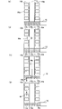
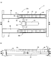
- FIG. (A) is a plan view of the storage area of the article storage apparatus of FIG. (A) and (b) are explanatory views which show the process at the time of carrying an article into the storage area of FIG. (A), (b), (c), and (d) are explanatory views showing a process for carrying out an article from the storage area of FIG. (A) is a plan view of the storage area of the storage area of FIG. 2, and (b) is a side view thereof.
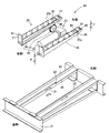
- (A) is a plan view of the transfer device of the embodiment of the present invention, and (b) is a side view thereof. It is an exploded perspective view of the storage area of the storage area of FIG.
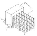
- the article storage device 1 of the present embodiment is largely composed of a loading / unloading area 2 and a storage area 3.
- the loading / unloading area 2 has a warehousing section 5, a warehousing section 6, and a series of transport paths 12 (FIG. 12), and is an area that fulfills a function of loading / unloading articles into / from the storage area 3.
- the loading / unloading area 2 has a three-story structure, and as shown in FIG. 12, a transport path 12 composed of a roller conveyor device is laid on each floor.
- a transport path 12 composed of a roller conveyor device is laid on each floor.
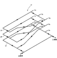
- the transport path on the first floor is a conveyor line that constitutes a counterclockwise one-way path as shown in FIG.
- the transport path on the second floor is a conveyor line that constitutes a clockwise one-way path as shown in FIG.
- the transport path on the third floor is a conveyor line that constitutes a clockwise one-way path as shown in FIG.
- the storage area 3 is an area for storing articles.
- the storage area 3 has a three-stage structure as shown in FIG. Further, as shown in FIG. 2, each stage has a structure in which three rows of conveyor devices are arranged in parallel. Of the three rows of conveyor devices, the outer two rows constitute the storage area.
- the central conveyor device constitutes the discharge path region.
- the conveyor device constituting the storage area is referred to as a storage conveyor (storage shelf portion) 10
- the conveyor device constituting the discharge path area is referred to as a discharge path conveyor (delivery path) 11.
- Both the storage conveyor 10 and the discharge channel conveyor 11 are divided into a plurality of zones. That is, the storage conveyor 10 and the discharge path conveyor 11 are formed by linearly connecting short conveyor devices 16 called zone conveyors.
- Each zone conveyor in each zone is a roller conveyor (also referred to as a roller conveyor), and a plurality of rollers (roller members) 15 are arranged in parallel at regular intervals.
- Each of the zone conveyors (short conveyor device 16) constituting each zone has an independent drive source and a control device, and can be individually driven and stopped.
- the transfer device 20 is spread under the storage conveyor 10 constituting the storage shelf portion.
- the transfer device 20 is a device for transferring articles on the storage conveyor 10 to the discharge channel conveyor (delivery channel) 11.
- the end of the storage area 3 is connected to the transport path 12 of the loading / unloading area 2 as shown in FIG.
- the transport path 12 is also connected to a conveyor device called a zone conveyor.
- Direction changing devices 13a, 13b, and 13c are arranged in the zone connected to the storage area 3 of the transport path 12.
- the direction changing devices 13a, 13b, and 13c can arbitrarily change the transport direction of the article. That is, the direction changing devices 13a, 13b, and 13c can make the article go straight, and can change the traveling direction of the article vertically in either the left or right direction.
- a series of operations for carrying in the article M is automatically executed by a command from a control device (not shown).
- the article M is carried in using the transport path 12 as shown in FIG. 3A.
- the direction changing device 13a connected to the storage conveyor 10a changes the transport direction to the storage conveyor 10a side, and sends the article M to the storage conveyor 10a.
- the article M advances to the back by the storage conveyor 10a. By repeating this operation, the article M is arranged in each zone of the storage conveyor 10a.
- the article M travels straight on the direction changing device 13a to reach the direction changing device 13c connected to the storage conveyor 10b. Then, the transfer direction is changed to the storage conveyor 10b by the direction changing device 13c, and the article M is sent to the storage conveyor 10b. The article M advances to the back by the storage conveyor 10b. By repeating this operation, the article M is arranged in each zone of the storage conveyor 10b.
- the article M can be carried out from any zone of the storage conveyors 10a and 10b.
- the article M is placed in each zone and the article Ma stored in the intermediate portion of the storage conveyor 10b is carried out, the article Ma is placed in the zone in which the article Ma is placed.
- the transfer device 20 is driven, and the article Ma is transferred from the storage conveyor 10b to the discharge channel conveyor 11 which is a delivery channel, as shown in FIG. 4 (b).
- the discharge path conveyor (delivery path) 11 is driven, placed on the transport path 12 via the direction changing device 13b as shown in FIG. 4 (c), and carried out to the left side of the drawing.
- the storage conveyor 10b was driven to drive the zone on the upstream side of the vacant zone, and the article placed in the vacant zone on the upstream side. Advance M.
- the storage conveyor 10 in the storage area 3 conveys articles in a one-way street from the direction changing devices 13a and 13c to the back side.
- the discharge path conveyor 11 in the storage area 3 conveys the article in a one-way street from the back side toward the direction changing device 13b.
- the article storage device 1 of the present embodiment since the article transport routes in the loading / unloading area 2 and the storage area 3 are both one-way, the articles can be continuously loaded / unloaded.
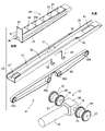
- the transfer device 20 Based on the posture in which the transfer device 20 is attached to the storage conveyor 10, the discharge path conveyor 11 side is referred to as the front side, and the opposite side is referred to as the rear side. As shown in FIGS. 6 and 7, the transfer device 20 includes a frame 21, two sets of transport units 22a and 22b, and a drive unit 23. Further, as shown in FIG. 9, the transport unit 22 is composed of a ramp 25 and a traveling body 26.
- the ramp 25 is an elongated traveling path having a groove-like cross section.
- the ramp 25 has a floor member 30.
- a part of the floor member 30 has an opening 31.
- the upper surface of the ramp 25 is open.
- an engaging piece 32 is provided in a part of the release portion.
- the engaging piece 32 projects in a direction parallel to the floor member 30 from the upper end of the side wall 33 of the ramp 25.
- the ramp 25 is attached to the frame 21 so that the floor member 30 tilts at an angle A with the front side facing up.
- the traveling body 26 is composed of a rotating body row 35 and a rack 36.
- the rotating body row 35 has a plurality of rollers (rotating bodies) 42 attached to the support frame 37.
- seven rollers 42 are provided.
- the number of rollers 42 is not limited.
- the support frame 37 has an elongated frame shape and has side wall members 38a and 38b and a rear end wall 41.
- the support frame 37 is a frame-shaped member as described above, and the top surface and the bottom surface are open.
- the side wall members 38a and 38b are elongated right-angled trapezoids. That is, as shown in FIG. 8, the length F of the front side (upper side) is shorter than the length R of the rear end side (lower side).
- the angle between the right-angled side 45 and the inclined side 46 is the same as or close to the inclined angle A of the inclined road 25 described above. That is, the angle B (FIG. 9) formed by the two sides of the side wall members 38a and 38b is substantially the same as the inclination angle A of the inclined path 25 described above.
- the rear end wall 41 of the support frame 37 is longer in the height direction than the rear end side (lower side) of the side wall members 38a and 38b, and protrudes upward as shown in FIG.
- the protruding portion of the rear end wall 41 functions as a pressing piece 50.
- the rollers 42 are rotatably attached to the support frame 37 in a row.
- the plurality of rollers 42 attached to the support frame 37 have different sizes, and the diameter of the rollers 42 attached to the front side is smaller than the diameter of the rollers on the rear side. In the present embodiment, the diameter of the roller 42 becomes smaller toward the front side.
- the lower portion of each roller 42 is exposed below the lower side surface. Similarly, the top of each roller 42 is exposed above the upper side.
- the roller 42 has a degree of freedom in the vertical direction in addition to the degree of freedom in the rotation direction. That is, the roller 42 is rotatably supported by the support frame 37 with play in the vertical direction.
- a contact piece 51 is provided at the head portion of the traveling body 26.
- the contact piece 51 is attached to the support frame 37 via a pin 48 and swings with respect to the support frame 37.
- the direction of the swing axis is the same as the rotation axis of the roller 42.
- a roller 43 is also provided on the contact piece 51.
- the roller 43 of the contact piece 51 also functionally constitutes a part of the rotating body row 35.
- the roller 43 of the contact piece 51 is rotatable, but does not have a degree of freedom in the vertical direction.
- the contact piece 51 is urged by the urging member 47 (FIG. 9) so as to have a standing posture as shown in FIG. 10 (c).
- the contact piece 51 is urged by the urging member 47 so as to project upward from the support frame 37.
- the urging member 47 is a spring.
- the contact piece 51 maintains a constant standing posture by a stopper (not shown).
- the contact piece 51 can resist the force (arrow C) from the front side to the rear side.
- a force is received from the rear side toward the front side (arrow D)
- the posture becomes almost horizontal and is immersed below the support frame 37.
- the rack 36 is attached along the lower side side of one side wall member 38a of the support frame 37.
- the teeth of the rack 36 are mounted facing down.
- the traveling body 26 is arranged in a groove-shaped region of the ramp 25.
- the total length of the traveling body 26 is shorter than the total length of the ramp 25.
- the rack 36 is in contact with the floor member 30 of the ramp 25.
- the rack 36 is arranged parallel to the ramp 25.
- the rollers 42 and 43 of the traveling body 26 the rollers 42 (rollers 42 of the rotating body row 35) other than the rollers 43 of the contact piece 51 are all in contact with the floor member 30 of the ramp 25.
- the roller 42 of the rotating body row 35 is supported by the support frame 37 in a state where there is play in the vertical direction, the roller 42 is stable in a state of being in contact with the ramp 25.
- the roller 43 of the contact piece 51 does not have a degree of freedom in the vertical direction, it is stable in a state of being supported by the contact piece 51.
- the angle B formed by the two sides of the side wall members 38a and 38b of the traveling body 26 is substantially the same as the inclination angle A of the inclined road 25, and the diameters of the rollers 42 and 43 increase toward the front side. Since the size is small, the straight line (transport surface 80) connecting the upper ends of the rollers 42 and 43 is horizontal when the traveling body 26 is arranged on the ramp 25.
- the drive unit 23 includes a geared motor 55, a gear box 56, and a pinion gear 57.
- the gear box 56 has a built-in bevel gear train (not shown) inside, and changes the direction of the rotation axis to the vertical direction.
- the output shaft 70 of the geared motor 55 is connected to the input shaft of the gearbox 56.
- the gearbox 56 has two output shafts 70, and pinion gears 57 are connected to the output shafts 70, respectively.
- the transport units 22a and 22b are arranged in parallel at intervals as shown in FIG.
- a drive unit 23 is installed between the two.
- the gard motor 55 of the drive unit 23 is integrally attached to the frame 21.
- the pinion gear 57 of the drive unit 23 reaches the lower portions of the transport units 22a and 22b, and a part of the pinion gear 57 enters the opening 31 of the floor member 30 and engages with the rack 36 inside. Therefore, when the gard motor 55 rotates, the pinion gear 57 rotates, and the rack 36 moves linearly in the ramp 25 in parallel with the ramp 25.
- each roller 42 receives a force from the floor member 30 of the ramp 25 and rotates.
- FIG. 10A when the traveling body 26 moves in the forward direction, each roller 42 rotates in the direction in which the article is sent out in the forward direction as shown by the arrow.
- the roller 43 of the contact piece 51 is not in contact with the floor member 30 and does not rotate.
- the contact piece 51 is pushed by the engaging piece 32 of the ramp 25 and is in a sleeping posture as shown in FIG. 10A.
- the contact piece 51 separates from the engaging piece 32 and takes a standing posture, and projects upward from the support frame 37 as shown in FIG. 10 (c).
- the traveling body 26 returns to the rear end, the contact piece 51 is pushed by the engaging piece 32 and returns to the sleeping posture, and is immersed below the support frame 37.
- the transfer device 20 corresponds to each zone of the storage conveyor (storage shelf) 10, and is installed one at the bottom of each zone.
- the positional relationship between the transfer device 20 and the storage conveyor 10 constituting the storage shelf is as shown in FIG. 5, and the transfer units 22a and 22b of the transfer device 20 are located between the rollers 15 of the storage conveyor 10.
- the drive unit 23 is arranged. Focusing on the height relationship between the two, when the rotating body row 35 of the transfer device 20 is at the lowest position, that is, when the rotating body row 35 is at the rearmost position, as shown in FIG. 10 (a).
- the upper ends of the rollers 42 and 43 of the rotating body row 35 are located below the upper ends of the rollers 15 of the storage conveyor 10 (hereinafter, the transport surface of the storage conveyor 10).
- the traveling body 26 moves to the front side, the rotating body row 35 gradually rises as shown in FIG. 10B, and the transport surface 80 of the rotating body row 35 is larger than the transport surface of the storage conveyor 10. Go up.
- the transport surface 80 of the rotating body row 35 always maintains a horizontal posture.
- the traveling body 26 is moved forward from the standby position, the rotating body row 35 is moved in the direction of climbing the ramp 25, and the traveling body 26 is moved backward.
- the final return operation of moving the rotating body row 35 to the standby position and returning it to the standby position is sequentially executed.
- the first going operation is an operation of moving the rotating body row 35 in the ascending direction
- the returning operation is an operation of moving the rotating body row 35 in the descending direction
- the second going operation is the operation of moving the rotating body row 35 in the descending direction. Is an operation of moving in the ascending direction again.
- the above-mentioned series of operations is automatically performed by a command of an upper control device (not shown).
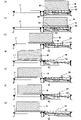
- the traveling body 26 In the stage before the transfer device 20 is driven, the traveling body 26 is in the standby position as shown in FIG. 11A. That is, the traveling body 26 is waiting on the rear end side. At this time, the transport surface 80 of the rotating body row 35 is below the transport surface of the storage conveyor 10. The pressing piece 50 at the rear of the traveling body 26 is above the transport surface of the storage conveyor 10. The contact piece 51 at the head of the traveling body 26 is pushed by the engaging piece 32 of the ramp 25 and is in a sleeping position, and is immersed below the transport surface of the storage conveyor 10.
- the traveling body 26 when the traveling body 26 is further moved in the forward direction, as shown in FIGS. 11 (d) and 11 (e), the article M moves to the front side by both the movement of the traveling body 26 itself and the rotation of the rotating body row 35. .. That is, since the article M is placed on the traveling body 26, when the traveling body 26 moves in the forward direction, the article M moves in the forward direction by the same amount as the moving amount. Further, the rollers 42 constituting the rotating body row 35 are in contact with the floor member 30 of the ramp 25, and when the traveling body 26 moves, each roller 42 is forced to receive a force from the floor member 30 of the ramp 25. It is rotated.
- each roller 42 rotates in the direction in which the article is sent out in the forward direction, so that the article M also moves to the discharge path conveyor 11 side by the urging force of each roller 42.
- the amount of movement of the article M is twice the amount of movement of the traveling body 26. Therefore, when the traveling body 26 moves to the most advanced position, the article M generally moves to the discharge path conveyor 11 side.
- the posture of the article M at this time is as shown in FIG. 11 (e), and the front end side is lowered to the discharge path conveyor 11 side to be in an inclined posture. That is, the rollers 42 constituting the rotating body row 35 are above the transport surface of the storage conveyor 10 and higher than the transport surface of the adjacent discharge path conveyor 11. Since more than half of the article M has moved to the discharge path conveyor 11 side, the article M changes to an inclined posture with the front side facing down due to the weight balance. As a result, the rear side of the article M is separated from the rollers 42 constituting the rotating body row 35 as shown in FIG. 11 (e).
- an intermediate return operation of moving the traveling body 26 in the rear direction and moving the rotating body row 35 in the direction of going down the ramp 25 is executed.
- the amount of movement of the traveling body 26 to the return side is about half of the total amount of movement.
- the contact piece 51 of the traveling body 26 is separated from the bottom of the article M.
- the article M is separated, and the obstacle on the contact piece 51 disappears. Therefore, the contact piece 51 is pushed by the urging member 47 into a standing posture, and protrudes above the transport surface of the storage conveyor 10.
- the traveling body 26 is moved in the forward direction, and the rotating body row 35 is moved in the direction of climbing the ramp 25 again to execute the second going operation.
- the contact piece 51 at the head of the traveling body 26 pushes the article M as shown in FIG. 11 (h), and the article M moves to the discharge path conveyor 11 side.
- the article M completely moves to the discharge path conveyor 11 side.
- the traveling body 26 is retracted, the traveling body 26 is retracted as shown in FIG. 11 (i), and the traveling body 26 is returned to the standby posture as shown in FIG. 11 (j).
- the moving means 81 for moving the rotating body train 35 is configured by the rack 36, the pinion gear 57, the geared motor 55 for driving the pinion gear 57, and the gear box 56.
- the present invention is not limited to this configuration, and the moving means may be configured by, for example, a cylinder or the like.
- rollers (rotating bodies) 42 of the rotating body row 35 are in contact with the ramp 25 and forcibly rotate, but the rollers that do not contact the ramp 25 and rotate freely are mixed. You may have.
- the rollers (rotating bodies) 42 constituting the rotating body row 35 are in contact with the ramp 25 and forcibly rotate to move the article M.
- the article M in addition to the movement of the rotating body row 35 itself, the article M can be moved by the urging force of the roller (rotating body) 42 that is forcibly rotated, and the article M is transferred more reliably. be able to.
- the amount of movement of the article M is theoretically twice the amount of movement of the traveling body 26.
- the present invention is not limited to this configuration, and the roller (rotating body) 42 may be rotated more to increase the amount of movement of the article M by the roller (rotating body) 42.
- the transfer device 60 having a function of accelerating the rotation of the roller (rotating body) 42 will be described.
- the members having the same functions as those of the previous embodiments and the members having the same functions are designated by the same numbers in the drawings, so that duplicate description will be omitted.
- the transfer device 60 of the second embodiment is composed of a frame 21, two sets of transfer units 22a and 22b, and a drive unit 23, similarly to the transfer device 20 of the first embodiment described above.
- the transport unit 22 is composed of a ramp 25, a drive mechanism 61, and a traveling body 26.
- a belt conveyor-like drive mechanism 61 is provided on the ramp 25.
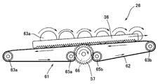
- the drive mechanism 61 is composed of an endless member 62 molded in an annular shape with rubber or resin, and a plurality of pulleys 63a, 63b, 65a, 65b, 66.
- the pulley 66 is a drive pulley and is attached to the output shaft 70 of the gard motor 55 as shown in FIG.
- two racks 36 are provided on the traveling body 26, and two pinion gears 57 engaging with the rack 36 are provided on the transport units 22a and 22b in accordance with the racks 36.
- the drive pulley 66 is attached between the two pinion gears 57.
- the floor member 30 of the ramp 25 is provided with two openings 31 corresponding to the two pinion gears 57. Further, the floor member 30 is provided with openings 67 at two places so that the endless member 62 can pass through. Since it is necessary to incorporate the endless member 62 into the ramp 25, the floor member 30 is composed of a plurality of members and can be removed (not shown).
- the plurality of pulleys 63a, 63b, 65a, 65b, 66 are all installed in the lower part of the floor member 30.
- the pulleys 63a and 63b are rotatably attached to ribs 82 provided on the frame 21.
- the pulleys 65a and 65b are rotatably attached to a rib 83 provided at the lower part of the ramp 25.
- the endless member 62 is suspended on the plurality of pulleys 63a, 63b, 65a, 65b, 66 described above. Then, as shown in FIG. 13, a part of the endless member 62 passes through the opening 67 of the floor member 30 and appears on the surface side of the floor member 30.
- the endless member 62 substantially constitutes the floor member of the ramp 25.
- the arrangement of the pulleys 63a, 63b, 65a, 65b, 66 is as shown in FIG. As shown in FIG. 13, the pulleys 63a and 63b are rotatably attached to the lower part of the floor member 30 in the vicinity of the opening 67.
- the pulleys 65a and 65b are arranged in the vicinity of the drive pulley 66 as shown in FIG.
- the pulleys 65a and 65b serve to press the front surface side of the endless member 62 against the drive pulley 66.
- the suspension path of the endless member 62 is as shown in FIG. 16, and the back surface side is suspended by pulleys 63a and 63b near the opening 67, the suspension path is greatly bent by the pulleys 65a and 65b, and the front surface side of the endless member 62 is a drive pulley. It is engaged with the upper side of 66.
- the moving direction of the rack 36 when the gard motor 55 is rotated and the rotation direction of the endless member 62 on the floor member 30 are opposite to each other.
- the endless member 62 rotates in a direction opposite to the moving direction of the rotating body row 35.
- the rollers 42 constituting the rotating body row 35 are all in contact with the endless member 62 which is the floor member 30 of the ramp 25, each roller 42 receives a force from the endless member 62 and rotates.
- each roller 42 since the endless member 62 itself rotates in the direction opposite to the moving direction of the rotating body row 35, each roller 42 is given a rotational force based on the linear movement of the rotating body row 35. A rotational force based on the rotation of the endless member 62 is also applied. Therefore, according to the transfer device 60 of the present embodiment, each roller 42 is rotated at a higher speed than the transfer device 20 of the previous embodiment. According to the transfer device 60 of the present embodiment, the amount of movement of the article M in the first forward movement is larger than that of the transfer device 20 of the previous embodiment.
- the contact piece 51 is provided at the head portion of the traveling body 26, but the transfer device 60 of the present embodiment does not have the contact piece.
- the transfer device 60 may be provided with the contact piece 51.
- the first going operation of moving the traveling body 26 in the forward direction from the standby position and moving the rotating body row 35 in the direction of climbing the ramp 25, and the traveling body 26 in the backward direction The intermediate return operation of moving the rotating body row 35 in the direction of going down the ramp, the second going operation of moving the rotating body row 35 in the direction of climbing the ramp 25 again, and going down the ramp 25 again.
- the final return operation of moving the rotating body row 35 in the direction and returning it to the standby position is sequentially executed.
- the traveling body 26 In the stage before the transfer device 20 is driven, the traveling body 26 is in the standby position and the traveling body 26 is waiting on the rear end side as shown in FIG. 17A. At this time, the transport surface 80 of the rotating body row 35 is below the transport surface of the storage conveyor 10.
- the article M moves to the front side by both the movement of the traveling body 26 itself and the rotation of the rotating body row 35, as in the previous embodiment and the like. That is, since the article M is placed on the traveling body 26, when the traveling body 26 moves in the forward direction, the article M moves in the forward direction by the same amount as the moving amount. Further, since the rollers 42 constituting the rotating body row 35 are in contact with the endless member 62, each roller 42 is forcibly rotated by receiving a force from the endless member 62. Here, since the endless member 62 rotates in a direction opposite to the moving direction of the rotating body row 35, each roller 42 is rotated at an increased speed as compared with the transfer device 20 of the previous embodiment. To. Therefore, as shown in FIG. 17D, the article M moves significantly as compared with the previous embodiment, and when the traveling body 26 moves to the cutting edge, the article M generally moves to the discharge path conveyor 11 side.
- the traveling body 26 is moved in the forward direction, and the rotating body row 35 is moved in the direction of climbing the ramp 25 again to execute the second going operation.
- the traveling body 26 is moved in the forward direction, the leading end of the traveling body 26 pushes the article M and the article M moves to the discharge path conveyor 11 side as shown in FIG. 17 (g).
- the traveling body 26 is retracted and the traveling body 26 is returned to the standby posture.
- the endless member 62 is provided on the floor member 30 of the ramp 25, but the endless member 62 is provided in the vicinity of the floor member 30 such as the side wall 53 of the ramp 25. May be good. Further, the floor member 30 of the ramp 25 may be eliminated, and a part or all of the ramp itself may be formed by the endless member 62.
- the lower portion of the roller (rotating body) 42 itself comes into direct contact with the floor member 30 and the endless member 62 of the ramp 25 and rotates, but the member integrated with the roller (rotating body) 42 is formed. It may come into contact with the floor member 30 or the endless member 62.
- a pulley or a friction wheel may be provided on the roller (rotating body) 42, and these may come into contact with the floor member 30 or the endless member 62 to rotate the roller (rotating body) 42.
- the rollers (rotating bodies) 42 constituting the rotating body row 35 are forcibly rotated to move the article M.
- the article M in addition to the movement of the rotating body row 35 itself, the article M can be moved by the urging force of the roller (rotating body) 42 that is forcibly rotated, and the article M is transferred more reliably. be able to.
- the present invention is not limited to this configuration, and the rollers (rotating bodies) 42 constituting the rotating body train 35 may be completely free-rotating.
- the traveling body 26 is moved forward from the standby position, the first going operation of moving the rotating body row 35 in the direction of climbing the ramp 25 is made faster, and the article M is twisted by the pressing piece 50 of the traveling body 26. Press hard.
- the article M is urged and moves on the freely rotating roller (rotating body) 42. That is, by strongly urging the article M with the freely rotating roller (rotating body) 42, the article M is rolled and moved, and the article M is moved more than the movement amount of the rotating body row 35 itself.
- the intermediate return operation, the second forward operation, and the final return operation are sequentially executed, and the article M is moved to the discharge path conveyor 11 side.
- the sizes of the plurality of rollers 42 attached to the support frame 37 are different, and the diameter of the rollers 42 becomes smaller toward the front side. Therefore, when the traveling body 26 is moved and raised, the transport surface of the rotating body row 35 becomes horizontal.
- the present invention is not limited to this configuration, and the transport surface of the rotating body row 35 may be moved up and down in an inclined state.
- the transfer device 20 is combined with the roller conveyor to form an area for storing articles, but a simple shelf and the transfer device 20 may be combined to provide an area for storing articles. That is, a slit may be provided in the shelf board, and the transport units 22a and 22b may be arranged under the slit.
- the transfer device 20 may be installed at the branch portion of the conveyor line. Further, a short roller conveyor such as a zone conveyor and the transfer device 20 of the present embodiment may be combined to form a transfer unit.
Landscapes
- Engineering & Computer Science (AREA)
- Mechanical Engineering (AREA)
- Warehouses Or Storage Devices (AREA)
Priority Applications (1)
| Application Number | Priority Date | Filing Date | Title |
|---|---|---|---|
| JP2022565509A JPWO2022114223A1 (https=) | 2020-11-30 | 2021-11-30 |
Applications Claiming Priority (2)
| Application Number | Priority Date | Filing Date | Title |
|---|---|---|---|
| JP2020198523 | 2020-11-30 | ||
| JP2020-198523 | 2020-11-30 |
Publications (1)
| Publication Number | Publication Date |
|---|---|
| WO2022114223A1 true WO2022114223A1 (ja) | 2022-06-02 |
Family
ID=81755638
Family Applications (1)
| Application Number | Title | Priority Date | Filing Date |
|---|---|---|---|
| PCT/JP2021/043887 Ceased WO2022114223A1 (ja) | 2020-11-30 | 2021-11-30 | 移載装置及び物品保管装置 |
Country Status (2)
| Country | Link |
|---|---|
| JP (1) | JPWO2022114223A1 (https=) |
| WO (1) | WO2022114223A1 (https=) |
Citations (3)
| Publication number | Priority date | Publication date | Assignee | Title |
|---|---|---|---|---|
| JPS4833087U (https=) * | 1971-08-23 | 1973-04-21 | ||
| US20150259156A1 (en) * | 2014-03-17 | 2015-09-17 | Facility Functions, Inc. | D wheel transfer device and method |
| JP2017178480A (ja) * | 2016-03-28 | 2017-10-05 | トヨタ自動車株式会社 | 移載装置 |
-
2021
- 2021-11-30 WO PCT/JP2021/043887 patent/WO2022114223A1/ja not_active Ceased
- 2021-11-30 JP JP2022565509A patent/JPWO2022114223A1/ja active Pending
Patent Citations (3)
| Publication number | Priority date | Publication date | Assignee | Title |
|---|---|---|---|---|
| JPS4833087U (https=) * | 1971-08-23 | 1973-04-21 | ||
| US20150259156A1 (en) * | 2014-03-17 | 2015-09-17 | Facility Functions, Inc. | D wheel transfer device and method |
| JP2017178480A (ja) * | 2016-03-28 | 2017-10-05 | トヨタ自動車株式会社 | 移載装置 |
Also Published As
| Publication number | Publication date |
|---|---|
| JPWO2022114223A1 (https=) | 2022-06-02 |
Similar Documents
| Publication | Publication Date | Title |
|---|---|---|
| US10087007B2 (en) | Cart-type transporting device | |
| CN110626691B (zh) | 分拣机器人及分拣方法 | |
| CN102976020A (zh) | 贯通式密集存储货架 | |
| FR3072954A1 (fr) | Appareil de transfert | |
| JP7485411B2 (ja) | 物品受け渡し手段 | |
| CN105189312A (zh) | 物品存储、分发及接收系统、装置、方法及应用 | |
| EP0594587B1 (en) | Car parking structure | |
| US2856081A (en) | Vehicle parking means | |
| WO2022114223A1 (ja) | 移載装置及び物品保管装置 | |
| CN113602725B (zh) | 一种料箱出入库系统 | |
| JP4078959B2 (ja) | 一時保管装置 | |
| CN112591362B (zh) | 一种管子立体存储系统 | |
| JP2945873B2 (ja) | 機械式立体駐車場 | |
| JP3268309B2 (ja) | 多段棚用搬送装置 | |
| US3915289A (en) | Endless conveyors with pivoted shelves and variable length control arms | |
| JP3653725B2 (ja) | 移載装置 | |
| CN114955597B (zh) | 一种箱装货物智能装车码垛设备 | |
| JP3463633B2 (ja) | 物品収納装置 | |
| JP2002226037A (ja) | 仕分け設備 | |
| CN111422598B (zh) | 转向输送系统 | |
| JP2005067823A (ja) | 板材搬送処理システム及びその使用方法 | |
| JPH0686247B2 (ja) | コンベヤにおける仕分装置 | |
| CN118701566A (zh) | 一种用于智能立体仓库的rgv中转装置 | |
| KR200332656Y1 (ko) | 다층형 주차타워 | |
| JP3905380B2 (ja) | 機械式駐車装置の自動車旋回装置 |
Legal Events
| Date | Code | Title | Description |
|---|---|---|---|
| 121 | Ep: the epo has been informed by wipo that ep was designated in this application |
Ref document number: 21898194 Country of ref document: EP Kind code of ref document: A1 |
|
| ENP | Entry into the national phase |
Ref document number: 2022565509 Country of ref document: JP Kind code of ref document: A |
|
| NENP | Non-entry into the national phase |
Ref country code: DE |
|
| 122 | Ep: pct application non-entry in european phase |
Ref document number: 21898194 Country of ref document: EP Kind code of ref document: A1 |