WO2022113283A1 - 空気調和機の室内機 - Google Patents
空気調和機の室内機 Download PDFInfo
- Publication number
- WO2022113283A1 WO2022113283A1 PCT/JP2020/044263 JP2020044263W WO2022113283A1 WO 2022113283 A1 WO2022113283 A1 WO 2022113283A1 JP 2020044263 W JP2020044263 W JP 2020044263W WO 2022113283 A1 WO2022113283 A1 WO 2022113283A1
- Authority
- WO
- WIPO (PCT)
- Prior art keywords
- heat exchanger
- clip
- corner
- portions
- indoor unit
- Prior art date
- Legal status (The legal status is an assumption and is not a legal conclusion. Google has not performed a legal analysis and makes no representation as to the accuracy of the status listed.)
- Ceased
Links
Images





Classifications
-
- F—MECHANICAL ENGINEERING; LIGHTING; HEATING; WEAPONS; BLASTING
- F24—HEATING; RANGES; VENTILATING
- F24F—AIR-CONDITIONING; AIR-HUMIDIFICATION; VENTILATION; USE OF AIR CURRENTS FOR SCREENING
- F24F1/00—Room units for air-conditioning, e.g. separate or self-contained units or units receiving primary air from a central station
- F24F1/0007—Indoor units, e.g. fan coil units
- F24F1/0043—Indoor units, e.g. fan coil units characterised by mounting arrangements
- F24F1/0047—Indoor units, e.g. fan coil units characterised by mounting arrangements mounted in the ceiling or at the ceiling
Definitions
- This disclosure relates to an indoor unit of an air conditioner installed on the ceiling, and particularly relates to a fixed structure of a heat exchanger in the indoor unit.
- indoor units of air conditioners installed on the ceiling are equipped with a heat exchanger in which a plurality of heat exchange units are laminated in the thickness direction. Further, some such indoor units are provided with brackets that are fixed to the top plate of the housing and simultaneously support a plurality of heat exchange portions in the heat exchanger (see, for example, Patent Document 1).
- the heat exchanger composed of a plurality of heat exchange portions is bent to form a substantially rectangular shape, and the inflow / out end portions and the folded ends which are the end portions on both sides of the heat exchanger. Brackets are placed at the corners diagonal to the ends.
- the bracket disclosed in Patent Document 1 includes a fixing portion fixed to the top plate, a support portion supporting the heat exchanger, and a connecting portion connecting the fixing portion and the support portion, and is substantially S-shaped. It has a shape.
- the support portion and the connecting portion are formed by bending a metal plate, and the support portion has a support surface on which the heat exchanger is placed, and an edge portion and a partition portion extending from the support surface toward the heat exchanger side.
- the fixing portion is screwed to the top plate, and is partitioned by a partition portion on the support surface between the edge portion and the connecting portion of the support portion, and the heat exchange portion inside and the outside heat in the thickness direction are partitioned.
- a configuration is such that a plurality of heat exchange portions are simultaneously supported and fixed to the top plate by being placed on the exchange portion and sandwiched between the exchange portion and the top plate.
- bracket is provided only in one corner of the heat exchanger as in Patent Document 1, it is not possible to sufficiently suppress the opening of the inner heat exchange portion and the outer heat exchange portion in the thickness direction.
- a substantially S-shaped bracket having a fixing portion as described in Patent Document 1 is provided not only in one corner of the heat exchanger but also in another position, the top plate is used. It becomes necessary to fix the heat exchanger at a plurality of places, and the assemblability and maintainability deteriorate.
- the present disclosure has been made to solve the above-mentioned problems, and has improved the effect of suppressing the opening between the heat exchange portions and avoided deterioration of assemblability and maintainability due to an increase in the number of fixing points.
- the purpose is to provide an indoor unit of an air conditioner.
- the indoor unit of the air conditioner according to the present disclosure is a heat exchanger having a plurality of heat exchange portions stacked in the thickness direction, has a polygonal shape in a plan view, and is adjacent to the plurality of corner portions.
- a housing having a plurality of linear side portions connecting the corners, the heat exchanger formed by the heat exchanger, and a top plate facing the upper end of the heat exchanger, and accommodating the heat exchanger.
- a heat exchanger mounting that has a fixing portion fixed to the top plate and a support portion that sandwiches and supports the plurality of heat exchange portions in the thickness direction, and attaches the heat exchanger to the top plate.
- a component and a clip that is attached to the lower end of the heat exchanger at a position different from the position of the heat exchanger mounting component in the plan view of the heat exchanger and sandwiches the plurality of heat exchangers in the thickness direction. Be prepared.
- the heat exchanger is sandwiched in the thickness direction at a plurality of points in a plan view by the heat exchanger mounting component and the clip attached to the lower end portion of the heat exchanger, and the heat exchanger mounting component is also disclosed. Since the heat exchanger is fixed to the housing, there is no need to increase the number of fixing points. Therefore, it is possible to improve the effect of suppressing the opening of the plurality of heat exchange portions stacked in the thickness direction in the thickness direction as compared with the conventional case, while avoiding deterioration of assemblability and maintainability such as an increase in fixing points.
- FIG. 6 is a schematic view showing the configuration of the first end portion of the heat exchanger to which the first end portion fixing component is attached.
- FIG. 6 is a schematic view showing the configuration of the second end portion of the heat exchanger to which the second end portion fixing component is attached.
- FIG. 1 It is a perspective view which shows the structure of the heat exchanger mounting component which is shown in FIG. It is a perspective view which shows the structure of the clip shown in FIG. It is explanatory drawing which shows the structure of the clip of FIG. It is an exploded view which shows the state before the clip attachment in the heat exchanger of FIG. It is a figure which shows the state after the clip is attached in the heat exchanger of FIG. It is a figure which shows the modification of the clip of FIG.
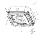
- FIG. 1 is an external perspective view of an indoor unit of the air conditioner according to the first embodiment.
- the indoor unit 100 of the first embodiment is a ceiling-mounted indoor unit that is embedded in the ceiling of the air-conditioned space or suspended from the ceiling of the air-conditioned space.
- the arrow X direction in FIG. 1 represents the width direction of the indoor unit 100
- the arrow Y direction represents the depth direction of the indoor unit 100
- the arrow Z direction represents the height direction of the indoor unit 100.
- the indoor unit 100 has an apparatus main body 2 including a housing 3 constituting the outer shell of the indoor unit 100, and a decorative panel 1.
- the housing 3 is a box body having a substantially rectangular parallelepiped shape in which an opening is formed on a surface to be a lower surface when the indoor unit 100 is installed on the ceiling, and the indoor unit 100 has four directions. It is said to be a 4-way blowout type indoor unit that blows out air.
- the decorative panel 1 is attached to the apparatus main body 2 so as to cover the opening of the housing 3.
- a suction port 1a is formed in the central portion of the decorative panel 1.
- the decorative panel 1 is formed with four outlets 1b so as to surround the suction port 1a.
- the indoor unit 100 is connected to an outdoor unit (not shown) by connecting pipes such as a liquid pipe and a gas pipe, and constitutes an air conditioner together with the outdoor unit.
- the indoor unit 100 has an indoor heat exchanger (FIG. 2 described later) that exchanges heat between the air in the air-conditioned space and the refrigerant.
- the indoor heat exchanger may be simply referred to as a heat exchanger 6.
- the compressor, four-way valve, outdoor heat exchanger and expansion valve of the outdoor unit (not shown) and the heat exchanger 6 of the indoor unit 100 are sequentially connected via pipes to form a refrigerant circuit. By circulating the refrigerant in the refrigerant circuit of the air conditioner, the indoor unit 100 heats or cools the air-conditioned space.
- FIG. 2 is an external perspective view of the apparatus main body 2 in the indoor unit of FIG.
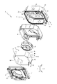
- FIG. 3 is an exploded perspective view of the apparatus main body 2 of FIG.
- FIG. 4 is a schematic view showing a state in which the heat exchanger 6 is fixed in the housing 3 in the apparatus main body 2 of FIG.
- FIG. 5 is a schematic configuration diagram of the heat exchanger 6. In FIG. 5, the flow direction of the airflow passing through each side of the heat exchanger 6 is indicated by a white arrow.
- FIG. 6 is a bottom view of FIG. 4. With reference to FIGS. 1 to 6, the configurations of the housing 3, the heat insulating material 4, the blower 5, the heat exchanger 6, the end fixing component 10, and the dew receiving component 7 in the apparatus main body 2 will be described.
- the apparatus main body 2 is composed of a blower 5 composed of a centrifugal fan such as a turbo fan and a plurality of layers in the housing 3, and heat is provided so as to surround the blower 5.
- the exchanger 6 and the like are arranged and configured.
- the apparatus main body 2 includes an end fixing component 10 and a heat exchanger mounting component 8 for fixing the heat exchanger 6 to the housing 3, and a clip 9 for sandwiching a plurality of layers of the heat exchanger 6.
- the end fixing parts 10 are arranged at the ends on both sides of the heat exchanger 6 in a plan view, and the heat exchanger 6 is fixed to the housing 3 at the upper portion thereof.
- the heat exchanger mounting component 8 is provided separately from the end fixing component 10, and mounts the heat exchanger 6 to the housing 3. Further, the apparatus main body 2 has a heat insulating material 4 provided along the inner surface of the housing 3 and a dew receiving component 7. Further, although not shown, the indoor unit 100 includes a valve for connecting the refrigerant pipe connected to the heat exchanger 6 and the connecting pipe from the outdoor unit.
- the housing 3 accommodates the heat exchanger 6 and is mounted on the ceiling.
- the housing 3 has a polygonal shape in a plan view.
- the lower surface of the housing 3 is open, and the housing 3 has a top plate 31 constituting the upper surface and a plurality of side plates extending downward from the edge of the top plate 31.
- a connecting plate 37 that connects adjacent side plates to each other.
- the right side plate 32 constitutes the right side surface of the housing 3
- the front side plate 33 constitutes the front side surface of the housing 3
- the left side plate 34 constitutes the left side surface of the housing 3, and the rear side plate 35.
- the valve mounting side plate 36 arranged on the right side and the front side of the rear side plate 35, the front side surface of the housing 3 is configured.
- a heat exchanger 6 and a blower 5 are installed in the housing 3.
- the blower 5 is installed at the center of the top plate 31 of the housing 3. Therefore, as shown in FIG. 3, a motor installation groove 3a in which the fan motor (not shown) of the blower 5 is arranged is formed in the central portion of the top plate 31 of the housing 3.
- the heat exchanger is provided so that the upper end 6u of the vertical end (arrow Z direction) of the heat exchanger 6 faces the top plate 31. 6 is attached. Therefore, as shown in FIG. 4, the top plate 31 of the housing 3 is formed with a recess 3b to which the heat exchanger mounting component 8 is fixed. The configuration of the heat exchanger mounting component 8 will be described later.
- a valve for connecting the connection pipe from the outdoor unit is installed in the rear right corner of the housing 3. More specifically, a liquid valve (not shown) connected to the liquid pipe of the connecting pipe and a gas valve connected to the gas pipe of the connecting pipe (not shown) are attached to the valve mounting side plate 36 constituting the right side portion of the rear side surface of the housing 3. (Fig.) Is installed. Therefore, the valve mounting side plate 36 of the housing 3 is formed with two valve mounting ports 3c in which a liquid valve and a gas valve are mounted.
- the heat insulating material 4 has substantially the same shape as the housing 3, and is provided along the inner surface of the housing 3 as shown in FIG.
- the heat insulating material 4 is made of, for example, styrofoam.
- the air in the indoor unit 100 and the housing 3 are insulated by the heat insulating material 4.
- blower 5 As shown in FIG. 2, the blower 5 is arranged in the central portion of the apparatus main body 2 so as to face the suction port 1a (FIG. 1) via the dew receiving component 7, and is insulated as shown in FIG. It is attached to the housing 3 via the material 4.
- the blower 5 is composed of an impeller including a plurality of blades 51, a fan motor (not shown), and the like, and the impeller is rotationally driven by the fan motor to blow out air in the centrifugal direction.
- the air in the interior space is sucked into the apparatus main body 2 through the suction port 1a (FIG. 1), supplied to the heat exchanger 6, passes through the heat exchanger 6 and becomes conditioned air. After that, it is blown into the indoor space through the air outlet 1b (FIG. 1).
- Heat exchanger 6 As shown in FIG. 3, the heat exchanger 6 is arranged inside the apparatus main body 2 and is installed in the housing 3 via the heat insulating material 4. Further, the heat exchanger 6 is arranged at a position on the outer peripheral side of the suction port 1a shown in FIG. 1 and on the inner peripheral side of the air outlet 1b in a plan view. The heat exchanger 6 exchanges heat between the refrigerant flowing inside the heat exchanger 6 and the air in the interior space sucked into the apparatus main body 2 by the blower 5.
- the heat exchanger 6 is composed of, for example, a fin tube type heat exchanger, and has a plurality of fins and a plurality of heat transfer tubes forming a flow path of the refrigerant in the heat exchanger 6, although not shown. ing. Each of the plurality of fins is arranged at a predetermined interval, and each of the heat transfer tubes penetrates the plurality of fins.
- the heat exchanger 6 is formed by bending and has a polygonal shape in a plan view. More specifically, in a plan view, the heat exchanger 6 is formed by a plurality of rounded corners 6e and a plurality of linear side portions 6f connecting two adjacent corners 6e. One of the plurality of corners 6e has an open shape. As shown in FIG. 4, the corner portion 6e0 opened in the heat exchanger 6 is formed in the corner where the valve mounting side plate 36 is arranged in a plan view. One of the ends on both sides forming the open corner portion 6e0 in the heat exchanger 6 is arranged so as to face the valve mounting port 3c in the housing 3, via the pipes 13a and 13b described later, and the liquid valve and the gas valve. Is connected to the external connection pipe.
- the ends connected to the external connecting pipes via the pipes 13a and 13b and the liquid valve and the gas valve are referred to as the first end portion 6a, and the first end is referred to as the first end.
- the other end of the portion 6a is referred to as a second end portion 6b.
- the heat exchanger 6 is formed in a pentagonal shape.
- the heat exchanger 6 has a first side portion 6f1, a second side portion 6f2, and a third side plate 32 provided along the right side plate 32, the front side plate 33, the left side plate 34, and the rear side plate 35 (FIG. 3) of the housing 3. It has a side portion 6f3 and a fifth side portion 6f5. Further, the heat exchanger 6 has a fourth side portion 6f4 provided between the third side portion 6f3 and the fifth side portion 6f5. Further, in the heat exchanger 6 shown in FIG. 5, there is an opening on the right side of the rear portion, that is, between the fifth side portion 6f5 and the first side portion 6f1.
- the corners diagonal to the opened corners 6e0 are referred to as the first corner 6e1 and the first corner.
- Each of the two corners adjacent to the portion 6e1 is referred to as a second corner portion 6e2, and the remaining corner portions are referred to as a third corner portion 6e3.
- the first corner portion 6e1 is provided between the second side portion 6f2 and the third side portion 6f3.
- the heat exchanger 6 shown in FIG. 5 has a first side portion 6f1 and a second corner on the first end portion 6a side from the first end portion 6a connected to the valve toward the first corner portion 6e1.
- the portion 6e2, the second side portion 6f2, and the first corner portion 6e1 are connected in this order.
- the first corner portion 6e1, the third side portion 6f3, and the second corner portion 6b on the second end portion 6b side are directed from the first corner portion 6e1 to the second end portion 6b. 6e2, the fourth side portion 6f4, the third corner portion 6e3, and the fifth side portion 6f5 are connected in this order.
- the heat exchanger 6 has a plurality of heat exchange units stacked in the thickness direction, that is, in the flow direction of the air flow.
- the heat exchanger 6 is composed of three layers of heat exchange portions in the flow direction of the air flow.
- the heat exchanger 6 shown in FIG. 5 has a first heat exchange unit 61 on the most upstream side, that is, the innermost peripheral side, and a third heat exchange unit 63 on the most downstream side, that is, the outermost peripheral side in the air flow direction. It is composed of a second heat exchange unit 62 provided between the first heat exchange unit 61 and the third heat exchange unit 63.
- Each of the first heat exchange unit 61, the second heat exchange unit 62, and the third heat exchange unit 63 has a polygonal shape in a plan view, and has a plurality of fins and a plurality of heat transfer tubes, although not shown. ing. In each heat exchange section, a plurality of corner portions 6e and a plurality of side portions 6f are connected to form a plurality of refrigerant flow paths.
- End fixing part 10 As shown in FIG. 4, the end fixing component 10 is attached to the first end 6a side of the heat exchanger 6 and is fixed to the top plate 31 with the first end fixing component 11 and the heat exchanger 6. It has a second end fixing part 12 attached to the second end 6b side of the above and fixed to the top plate 31.
- the first end fixing part 11 and the second end fixing part 12 are each made of, for example, sheet metal.
- the first end fixing component 11 sandwiches the heat exchanger 6 in the thickness direction to connect the first heat exchange section 61, the second heat exchange section 62, and the third heat exchange section 63. It has a connecting portion 11a and a fixing portion 11b provided at the upper end of the connecting portion 11a and fixed to the top plate 31.
- the connecting portion 11a has a substantially U-shape that is angular in a plan view, and heat exchanges from both sides of the end face portion 111 that contacts the end face of the first end portion 6a of the heat exchanger 6 and covers the end face. It has two side surface portions 112 extending along the respective side surfaces of the upstream side and the downstream side of the air flow of the vessel 6.
- the upstream side surface of the airflow in the heat exchanger 6 is referred to as an upstream side surface 6su
- the downstream side surface of the airflow in the heat exchanger 6 is referred to as a downstream side surface 6sd.
- the fixing portion 11b has a flat plate shape extending inward from the side surface portion 112 on the upstream side in parallel with the top plate 31 at the upper end of the connecting portion 11a, and is larger than the heat exchanger 6. It is located on the upstream side of the airflow.
- the fixing portion 11b is formed with a hole through which a screw for fixing the fixing portion 11b to the top plate 31 is inserted.
- the second end fixing component 12 has a connecting portion 12a and a connecting portion 12a that sandwich the heat exchanger 6 in the thickness direction and connect the first heat exchange portion 61, the second heat exchange portion 62, and the third heat exchange portion 63. It has a fixing portion 12b provided at the upper end of the top plate 31 and fixed to the top plate 31.
- the connecting portion 12a has a substantially U-shape that is angular in a plan view, and heat exchanges from both sides of the end face portion 121 that contacts the end face of the second end portion 6b of the heat exchanger 6 and covers the end face. It has two side surface portions 122 extending along the upstream side surface 6su and the downstream side surface 6sd of the vessel 6, respectively. In the example shown in FIG.
- the fixing portion 12b has a flat plate shape extending inward from the upstream side surface portion 122 in parallel with the top plate 31 at the upper end of the connecting portion 12a, and has an air flow more than that of the heat exchanger 6. It is located on the upstream side of.
- the fixing portion 12b is formed with a hole through which a screw for fixing the fixing portion 12b to the top plate 31 is inserted.
- FIG. 7 is a schematic view showing the configuration of the first end portion 6a of the heat exchanger 6 to which the first end portion fixing component 11 is attached in FIG.
- a plurality of circular holes are formed in the end face portion 111 of the first end portion fixing component 11.
- some of the heat transfer tubes pass through the hole of the end face portion 111 and the pipe 13a.
- a gas valve (not shown).
- the remaining heat transfer tubes are the plurality of second heat exchange sections 62 via the holes of the end face portions 111 and the U-shaped tube 14a. It is connected to some of the heat transfer tubes. Further, in the first end portion 6a, among the plurality of heat transfer tubes of the first heat exchange section 61 arranged on the innermost side of the heat exchanger 6, some of the heat transfer tubes have holes and pipes 13b of the end face portion 111. It is connected to a liquid valve (not shown) via.
- the remaining heat transfer tubes are the plurality of second heat exchange sections 62 via the holes of the end face portions 111 and the U-shaped tube 14b. It is connected to the remaining heat transfer tubes of the heat transfer tubes.
- FIG. 8 is a schematic view showing the configuration of the second end portion 6b of the heat exchanger 6 to which the second end portion fixing component 12 is attached in FIG.
- a plurality of circular holes are formed in the end face portion 121 of the second end portion fixing component 12.
- the heat transfer tubes adjacent to each other in the vertical direction (arrow Z direction) of the plurality of heat transfer tubes of the third heat exchanger 63 arranged on the outermost side of the heat exchanger 6 are the holes of the end face portion 121 and the heat transfer tubes. They are connected to each other via a U-shaped tube 14c.
- the heat transfer tubes adjacent to each other in the vertical direction (arrow Z direction) of the plurality of heat transfer tubes of the first heat exchange portion 61 arranged on the innermost side of the heat exchanger 6 are holes in the end face portion 121. And connected to the difference via the U-tube 14e. Further, in the second end portion 6b, the heat transfer tubes adjacent to each other in the vertical direction (arrow Z direction) of the plurality of heat transfer tubes of the second heat exchange portion 62 are connected to each other via a hole in the end face portion 121 and a U-shaped tube 14d. To.
- the gaseous refrigerant flowing into the pipe 13a (FIG. 7) through a gas valve (not shown) is transferred from the first end portion 6a to the heat exchanger 6 It flows into the refrigerant flow path of the above and flows through the refrigerant flow path.
- the refrigerant liquefies by radiating heat to the air supplied by the blower 5 (FIG. 2), and then flows out from the heat exchanger 6 via the first end portion 6a. do.
- the refrigerant flowing out of the heat exchanger 6 flows out from the indoor unit 100 (FIG. 1) via the pipe 13b (FIG.
- the liquid refrigerant flowing into the pipe 13b (FIG. 7) through a liquid valve (not shown) is transferred from the first end portion 6a to the heat exchanger 6 It flows into the refrigerant flow path of the above and flows through the refrigerant flow path.
- the refrigerant is gasified by absorbing heat from the air supplied by the blower 5 (FIG. 2), and then flows out from the heat exchanger 6 via the first end portion 6a. do.
- the refrigerant flowing out of the heat exchanger 6 flows out from the indoor unit 100 (FIG. 1) via the pipe 13a (FIG.
- the dew receiving component 7 is arranged on the lower surface of the housing 3 so as to cover the lower end 6d of the heat exchanger 6.
- a circular central opening 7a is formed at a position facing the suction port 1a formed in the central portion of the decorative panel 1 shown in FIG. 1, as shown in FIG. There is.
- a square-shaped side opening 7b is formed at a position facing each of the four outlets 1b of the decorative panel 1 shown in FIG. 1, as shown in FIG. ..
- the dew point temperature may be reached when the air in the indoor space is cooled by the heat exchanger 6, and dew condensation may occur on the heat exchanger 6. Then, the dew adhering to the heat exchanger 6 may fall from the heat exchanger 6.
- the dew receiving component 7 is configured to receive the dew that has fallen from the heat exchanger 6 below the heat exchanger 6.
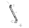
- FIG. 9 is a perspective view showing the configuration of the heat exchanger mounting component 8 shown in FIG. The configuration of the heat exchanger mounting component 8 will be described with reference to FIGS. 4, 6 and 9.
- the heat exchanger mounting component 8 is arranged between the first end portion 6a and the second end portion 6b of the heat exchanger 6 and mounts the heat exchanger 6 to the housing 3. Is.
- the heat exchanger mounting component 8 is made of, for example, sheet metal.
- the heat exchanger mounting component 8 includes a fixing portion 83 fixed to the top plate 31, a support portion 81 that sandwiches and supports the heat exchanger 6 in the thickness direction, and a fixing portion 83 and a support. It is composed of a connecting portion 82 connecting the portion 81 and having a substantially S-shape.
- the connecting portion 82 has a vertically long flat plate shape, and as shown in FIG. 4, has a length similar to the length in the vertical direction (arrow Z direction) of the heat exchanger 6.
- the fixing portion 83 of the heat exchanger mounting component 8 has a flat plate shape extending inward from the upper end of the connecting portion 82 in a direction substantially perpendicular to the connecting portion 82.
- a hole 83a through which a screw is inserted is formed in the fixing portion 83.
- the support portion 81 has a flat plate-shaped support surface 81a extending outward from the lower end of the connection portion 82 in a direction substantially perpendicular to the connection portion 82, and a regulation surface 81b extending upward from the tip of the support surface 81a, and is connected.
- the lower end portion of the heat exchanger 6 (FIG. 4) is sandwiched between the portion 82 and the portion 82.
- the width of the support surface 81a in the airflow direction that is, the distance between the connection portion 82 and the regulation surface 81b is set to be about the same as the thickness T in the airflow direction of the heat exchanger 6, as shown in FIG. ing.
- the support portion 81 is mounted on the lower end portion of the heat exchanger 6 to sandwich the heat exchanger 6 in the thickness direction, and the connecting portion 82 heats up. It is arranged along the upstream side surface 6su of the exchanger 6, and the fixing portion 83 is arranged in the recess 3b of the top plate 31. Then, when the fixing portion 83 of the heat exchanger mounting component 8 is screwed to the top plate 31 in the recess 3b, the heat exchanger 6 is supported by the support portion 81 via the fixing portion 83 and the connecting portion 82.
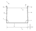
- FIG. 10 is a perspective view showing the configuration of the clip 9 shown in FIG.
- FIG. 11 is an explanatory diagram showing the configuration of the clip 9 of FIG. The configuration of the clip 9 will be described with reference to FIGS. 4, 6, 10 and 11.
- the clip 9 has a substantially U-shape that is angular when viewed from the side.
- the clip 9 includes a clip bottom surface portion 91, two clip side surface portions 92 extending upward from both ends of the clip bottom surface portion 91, and a clip tip portion 93 provided continuously with the upper end of each clip side surface portion 92. Have.
- the clip tip portion 93 can be omitted.
- the clip 9 is made of, for example, a sheet metal, and by bending the sheet metal, a continuous clip bottom surface portion 91, a clip side surface portion 92, and a clip tip portion 93 are formed.
- the width of the clip bottom surface portion 91 shown in FIG. 11, that is, the distance L1 between the lower ends of the two clip side surface portions 92 is equal to the thickness T of the heat exchanger 6 shown in FIG. 6 in the airflow direction.
- Clip 9 is formed. Further, as shown in FIG. 11, the clip 9 is formed so that the angle ⁇ formed on the upper surface side of the clip bottom surface portion 91 by the clip bottom surface portion 91 and the clip side surface portion 92 is an acute angle of less than 90 degrees. ing. Therefore, the distance L2 between the upper ends of the two clip side surface portions 92 shown in FIG. 11 is shorter than the thickness T in the airflow direction of the heat exchanger 6 shown in FIG.
- the clip tip portion 93 has a shape inclined outward so that the distance L3 between the two clip tip portions 93 gradually increases from the lower side connected to the clip side surface portion 92 toward the upper side.
- FIG. 12 is an exploded view showing a state of the heat exchanger 6 of FIG. 4 before mounting the clip 9.
- FIG. 13 is a diagram showing a state of the heat exchanger 6 of FIG. 4 after the clip 9 is attached.
- the clip 9 is attached to the heat exchanger 6 from the lower side of the heat exchanger 6 from the clip tip portion 93 side, and as shown in FIG. 13, between the two clip side surface portions 92.
- the lower end of the heat exchanger 6 is arranged.
- the two clip tip portions 93 are inclined outward. Therefore, the lower end portion of the heat exchanger 6 can be easily inserted, and when the edge of the lower end portion 6d of the heat exchanger 6 is pressed against the clip tip portion 93, the two clip side surface portions 92 open to open the heat exchanger 6. Since the lower end portion is inserted, the clip 9 can be easily attached to the heat exchanger 6.
- the upper surface of the clip bottom surface portion 91 is in contact with the lower end 6d of the heat exchanger 6, and the two clip side surface portions 92 are the heat exchanger 6 In contact with the upstream side surface 6su and the downstream side surface 6sd, respectively.
- each clip side surface portion 92 with the clip bottom surface portion 91 is an acute angle
- two clips are formed depending on the thickness of the heat exchanger 6.
- the distance L2 (FIG. 11) between the upper ends of the side surface portions 92 is widened. Then, in a state where the clip 9 is attached to the heat exchanger 6, a reaction force is generated on the two spread side surface portions 92 of the clip, so that the clip 9 sandwiches the heat exchanger 6 in the thickness direction. Therefore, the opening in the thickness direction between the plurality of heat exchange portions in the heat exchanger 6 is suppressed, and the clip 9 attached to the heat exchanger 6 is less likely to come off.
- the airflow can be easily flowed in the thickness direction of the heat exchanger 6.
- FIG. 14 is a diagram showing a modified example of the clip of FIG.
- each clip side surface portion 92 is formed with a plurality of slits 92a extending in the vertical direction (arrow Z direction), that is, in the direction from the clip bottom surface portion 91 toward the clip tip portion 93.
- the air flows into the gap between the fins of the heat exchanger 6 or flows out from the gap between the fins of the heat exchanger 6. It is possible to prevent the clip side surface portion 92 from obstructing the flow of air. Therefore, even when the clip 9 is attached to the heat exchanger 6, it is possible to suppress the deterioration of the heat exchange performance of the heat exchanger 6 due to the clip 9.
- the heat exchanger mounting component 8 has a plurality of corner portions (first corner portion 6e1, two second corner portions 6e2, and a third) between the first end portion 6a and the second end portion 6b of the heat exchanger 6.
- the corner portion 6e3) and a plurality of side portions are arranged in any of the portions.
- a plurality of laminated heat exchange units are used.
- the heat exchanger mounting component 8 is arranged on the side of the corner portion 6e or the corner portion 6e of the side portion 6f in the heat exchanger 6.
- the side of the corner portion 6e in the side portion 6f means a position closer to the corner portion 6e than the center of the side portion 6f.
- the heat exchanger 6 is extremely heat exchanged at a specific position. It is possible to prevent the opening of the air from becoming large.
- the side portion (second side portion 6f2 or third side portion 6f3) connected to the opened corner portion 6e0 and the first corner portion 6e1 at the diagonal position or the first corner portion 6e1.
- the heat exchanger mounting component 8 is arranged on the side of the first corner portion 6e1 in the above.
- the heat exchanger mounting component 8 is the first in the heat exchanger 6 in the second side portion 6f2 connected to the first corner portion 6e1 at the diagonal position with the opened corner portion 6e0. It is arranged on the side of the corner portion 6e1.
- the clip 9 is located between the first end portion 6a and the second end portion 6b at a position different from the position where the heat exchanger mounting component 8 is arranged, preferably a plurality of corners. It is arranged in a portion different from the portion in which the heat exchanger mounting component 8 is arranged among the portion and the plurality of side portions.
- the corner portion different from the first corner portion 6e1 (two second corner portions 6e2)
- the clip 9 is arranged in either of them or in the vicinity of the third corner portion 6e3).
- a clip 9 is provided on the side of the second corner portion 6e2 in the first side portion 6f1 connected to the second corner portion 6e2 adjacent to the first corner portion 6e1.
- both the heat exchanger mounting component 8 and the clip 9 are arranged on the sides as shown in FIG. 6, the clip 9 is arranged with the heat exchanger mounting component 8 in the heat exchanger 6. It is preferable that the side portion (first side portion 6f1) different from the side portion (second side portion 6f2) is arranged.
- the indoor unit 100 of the air conditioner includes a heat exchanger 6 having a plurality of heat exchange portions stacked in the thickness direction, and a housing 3 accommodating the heat exchanger 6. , A heat exchanger mounting component 8 and a clip 9.
- the heat exchanger 6 has a polygonal shape in a plan view, and is formed by a plurality of corner portions 6e and a plurality of linear side portions 6f connecting two adjacent corner portions 6e.
- the housing 3 has a top plate 31 facing the upper end 6u of the heat exchanger 6 and accommodates the heat exchanger 6.
- the heat exchanger mounting component 8 has a fixing portion 83 fixed to the top plate 31 and a support portion 81 for sandwiching and supporting a plurality of heat exchange portions in the thickness direction, and the heat exchanger 6 is supported by the top plate 31. Attach to.
- the clip 9 is attached to the lower end portion of the heat exchanger 6 at a position different from the position of the heat exchanger mounting component 8 in the plan view of the heat exchanger 6, and sandwiches the plurality of heat exchanger portions in the thickness direction.
- the heat exchanger 6 is sandwiched in the thickness direction at a plurality of points in a plan view by the heat exchanger mounting component 8 and the clip 9 attached to the heat exchanger 6, and the heat exchange is performed by the heat exchanger mounting component 8. Since the vessel 6 is fixed to the housing 3, it is not necessary to increase the number of fixing points such as screw fixing. Therefore, it is possible to improve the effect of suppressing the opening of the plurality of heat exchange portions stacked in the thickness direction in the thickness direction as compared with the conventional case, while avoiding deterioration of assemblability and maintainability such as an increase in fixing points.
- one corner (corner portion 6e0) of the polygonal shape is open.
- the heat exchanger mounting component 8 is the first corner portion 6e1 diagonal to the opened corner of the plurality of corner portions 6e of the heat exchanger 6, or the first corner portion 6e1 of the plurality of side portions 6f. It is arranged on the side of the first corner portion 6e1 in the connected side portion (second side portion 6f2 or third side portion 6f3).
- the clip 9 has a second corner portion 6e2 different from the first corner portion 6e1 among the plurality of corner portions 6e of the heat exchanger 6, or a side portion (second) connected to the second corner portion 6e2 among the plurality of side portions 6f. It is arranged on the side of the second corner portion 6e2 in the side portion 6f2 or the first side portion 6f1).
- the heat exchanger 6 is located near the corner portion 6e (first corner portion 6e1) or the corner portion 6e (first corner portion 6e1), which is an intermediate position of the heat exchanger 6 in which the heat exchange portions are likely to open. Is sandwiched in the thickness direction, so that the opening between the heat exchange portions can be effectively suppressed.
- the second corner portion 6e2 is a corner portion adjacent to the first corner portion 6e1 among the plurality of corner portions 6e of the heat exchanger 6.
- the heat exchangers 6 are sandwiched in the thickness direction at the adjacent corners in two steps, so that the heat exchangers 6 are particularly heat exchanged in the section between the first end 6a and the second end 6b of the heat exchanger 6. It can be configured to suppress the opening intensively by providing it in a place where the opening is likely to occur.
- the heat exchanger mounting component 8 and the clip 9 are arranged on different side portions (for example, the second side portion 6f2 and the first side portion 6f1) in the heat exchanger 6. As a result, the heat exchanger mounting component 8 and the clip 9 can efficiently suppress the opening between the heat exchange portions that occur at the different side portions where the corner portions are interposed.
- the clip 9 is formed continuously with a clip bottom surface portion 91 facing the lower end 6d of the heat exchanger 6 and each of the clip bottom surface portions 91, and both side surfaces (upstream side surface 6su and downstream side surface) in the thickness direction of the heat exchanger 6 are formed. It has two clip side surface portions 92, which are in contact with the side surface 6sd). As a result, a clip 9 that can be easily attached to and detached from the heat exchanger 6 and is easily manufactured can be obtained.
- the clip side surface portion 92 is inclined so that the angle ⁇ formed with the clip bottom surface portion 91 is an acute angle.
- the tip of the clip 9 (clip tip 93) is inclined outward. As a result, the lower end 6d of the heat exchanger 6 can be easily inserted, and the clip 9 can be easily attached to the heat exchanger 6 by pressing the lower end 6d of the heat exchanger 6 against the clip tip portion 93.
- the embodiment is not limited to the above-described first embodiment, and can be appropriately modified or omitted.
- the combination of the shape of the heat exchanger 6 and the parts constituting the heat exchanger 6 is not limited to those described above.
- the shape of the heat exchanger mounting component 8 is not limited to the shape shown in FIG.
- the heat exchanger mounting component 8 may have any shape as long as it is fixed to the housing 3 and supports the heat exchanger 6 by sandwiching it in the thickness direction.
- the shape of the clip 9 is not limited to that shown in FIGS. 10 to 11.
- the clip 9 may have any shape as long as it sandwiches the heat exchanger 6 in the thickness direction and is attached to the heat exchanger 6.
- the number of clips 9 is not limited to this. Only one clip 9 may be provided in the heat exchanger 6, or three or more clips 9 may be provided. The number of clips 9 may be appropriately determined, for example, according to the number of corners constituting the heat exchanger 6.
- 1 Decorative panel 1a suction port, 1b outlet, 2 device body, 3 housing, 3a motor installation groove, 3b recess, 3c valve mounting port, 4 heat insulating material, 5 blower, 6 heat exchanger, 6a 1st end , 6b 2nd end, 6d lower end, 6e, 6e0 corner, 6e1 1st corner, 6e2 2nd corner, 6e3 3rd corner, 6f side, 6f1 1st side, 6f2 2nd side, 6f3 3rd side, 6f4 4th side, 6f5 5th side, 6sd downstream side, 6su upstream side, 6u top, 7 dew receiving parts, 7a center opening, 7b side opening, 8 heat exchanger mounting Parts, 9 clips, 10 end fixing parts, 11 1st end fixing parts, 11a connecting part, 11b fixing part, 12 2nd end fixing parts, 12a connecting part, 12b fixing part, 13a, 13b piping, 14a, 14b, 14c, 14d, 14e U-
Landscapes
- Engineering & Computer Science (AREA)
- Chemical & Material Sciences (AREA)
- Combustion & Propulsion (AREA)
- Mechanical Engineering (AREA)
- General Engineering & Computer Science (AREA)
- Air Filters, Heat-Exchange Apparatuses, And Housings Of Air-Conditioning Units (AREA)
Abstract
空気調和機の室内機は、厚み方向に積層された複数の熱交換部を有する熱交換器であって、平面視において多角形状を有し、複数の角部と、隣り合う2つの角部を接続する直線状の複数の辺部と、により形成された熱交換器と、熱交換器の上端と対向する天板を有し、熱交換器を収容する筐体と、天板に固定される固定部と、複数の熱交換部を厚み方向に挟み込んで支持する支持部と、を有し、熱交換器を天板に対して取り付ける熱交換器取付部品と、熱交換器の平面視において熱交換器取付部品の位置とは異なる位置で熱交換器の下端部に取り付けられ、複数の熱交換部を厚み方向に挟み込むクリップと、を備える。
Description
本開示は、天井に設置される空気調和機の室内機であって、特に室内機における熱交換器の固定構造に関する。
天井に設置される空気調和機の室内機(以下、単に室内機という)において、複数の熱交換部が厚み方向に積層されて構成される熱交換器を備えたものがある。また、このような室内機において、筐体の天板に固定され、熱交換器における複数の熱交換部を同時に支持するブラケットを備えたものがある(例えば、特許文献1参照)。特許文献1に開示された室内機において、複数の熱交換部から成る熱交換器は折り曲げられて略矩形状に形成されており、熱交換器において両側の端部である流入出端部及び折返し端部に対して対角位置の角部に、ブラケットが配置されている。特許文献1に開示されたブラケットは、天板に固定される固定部と、熱交換器を支持する支持部と、固定部と支持部との間を繋ぐ連結部と、を備え、略S字形状を有している。支持部と連結部とは金属板を折り曲げて形成され、支持部は、熱交換器が載せられる支持面と、支持面から熱交換器側に向かって延びる縁部と仕切部とを有している。そして、ブラケットにおいて、固定部が天板にネジ固定され、支持部の縁部と連結部との間の支持面の上に仕切部で仕切られて厚み方向の内側の熱交換部と外側の熱交換部とが載せ置かれ、天板との間に挟み込まれることにより、複数の熱交換部を同時に支持しつつ、天板に対して固定する構成とされる。
しかしながら、特許文献1のようにブラケットを、熱交換器の一角部に設けるだけでは、内側の熱交換部と外側の熱交換部との厚み方向の開きを十分に抑制することができない。かといって、特許文献1に記載されるような、固定部を有する略S字形状のブラケットを、熱交換器の一角部だけでなく他の位置にも設ける場合には、天板に対して熱交換器を複数箇所で固定する必要が生じてしまい、組立性及びメンテナンス性が悪化する。
本開示は、上記のような課題を解決するためになされたもので、熱交換部の間の開き抑制の効果を向上させるとともに、固定する箇所の増加による組立性及びメンテナンス性の悪化を回避した空気調和機の室内機を提供することを目的とする。
本開示に係る空気調和機の室内機は、厚み方向に積層された複数の熱交換部を有する熱交換器であって、平面視において多角形状を有し、複数の角部と、隣り合う2つの角部を接続する直線状の複数の辺部と、により形成された前記熱交換器と、前記熱交換器の上端と対向する天板を有し、前記熱交換器を収容する筐体と、前記天板に固定される固定部と、前記複数の熱交換部を厚み方向に挟み込んで支持する支持部と、を有し、前記熱交換器を前記天板に対して取り付ける熱交換器取付部品と、前記熱交換器の平面視において前記熱交換器取付部品の位置とは異なる位置で前記熱交換器の下端部に取り付けられ、前記複数の熱交換部を厚み方向に挟み込むクリップと、を備える。
本開示によれば、熱交換器取付部品と、熱交換器の下端部に取り付けられるクリップとにより、平面視において熱交換器が複数の箇所で厚み方向に挟み込まれ、また、熱交換器取付部品により熱交換器が筐体に対して固定されるので固定箇所を増やす必要がない。したがって、固定箇所の増加といった組立性及びメンテナンス性の悪化を回避しつつ、厚み方向に積層された複数の熱交換部の厚み方向の開き抑制の効果を従来よりも向上させることができる。
実施の形態1.
図1は、実施の形態1に係る空気調和機の室内機の外観斜視図である。実施の形態1の室内機100は、空調対象空間の天井に埋め込まれて、あるいは空調対象空間の天井に吊り下げられて設置される、天井設置型の室内機とされている。図1の矢印X方向は室内機100の幅方向を表し、矢印Y方向は室内機100の奥行き方向を表し、矢印Z方向は室内機100の高さ方向を表している。
図1は、実施の形態1に係る空気調和機の室内機の外観斜視図である。実施の形態1の室内機100は、空調対象空間の天井に埋め込まれて、あるいは空調対象空間の天井に吊り下げられて設置される、天井設置型の室内機とされている。図1の矢印X方向は室内機100の幅方向を表し、矢印Y方向は室内機100の奥行き方向を表し、矢印Z方向は室内機100の高さ方向を表している。
室内機100は、室内機100の外郭を構成する筐体3を含む装置本体2と、化粧パネル1と、を有している。実施の形態1では、筐体3は、室内機100が天井に設置された際に下面となる面に開口部が形成された略直方体形状を有する箱体とされ、室内機100は、4方向に空気を吹き出す4方向吹出型の室内機とされている。化粧パネル1は、筐体3の開口部を覆うように装置本体2に取り付けられている。化粧パネル1の中央部には、吸込口1aが形成されている。また化粧パネル1には、吸込口1aを囲むように、4つの吹出口1bが形成されている。
室内機100は、図示していない室外機と、液管及びガス管といった接続配管により接続され、室外機とともに空気調和機を構成する。室内機100は、空調対象空間の空気と冷媒との熱交換を行う室内熱交換器(後述する図2)を有している。以下、室内熱交換器を単に熱交換器6と称する場合がある。図示していない室外機の圧縮機、四方弁、室外熱交換器及び膨張弁と、室内機100の熱交換器6とが、配管を介して順次接続されて冷媒回路を構成している。空気調和機の冷媒回路に冷媒が循環することで、室内機100において空調対象空間の暖房又は冷房を行う。
図2は、図1の室内機における装置本体2の外観斜視図である。図3は、図2の装置本体2の分解斜視図である。図4は、図2の装置本体2における筐体3内に熱交換器6が固定された状態を示す概略図である。図5は、熱交換器6の概略構成図である。図5には、熱交換器6の各辺を通過する気流の流通方向が白抜き矢印で示されている。図6は、図4の下面図である。図1~図6を参照しつつ、装置本体2における筐体3、断熱材4、送風機5、熱交換器6、端部固定部品10、及び露受け部品7の構成について説明する。
図3に示されるように、装置本体2は、筐体3内に、例えばターボファン等の遠心ファンで構成された送風機5と、複数の層から成り、送風機5を囲むように設けられた熱交換器6等と、が配置されて構成されている。また装置本体2は、熱交換器6を筐体3に対して固定するための端部固定部品10及び熱交換器取付部品8と、熱交換器6の複数の層を挟み込むクリップ9と、を有する。端部固定部品10は、平面視した熱交換器6の両側の端部に配置されて、その上部において熱交換器6を筐体3に固定する。熱交換器取付部品8は、端部固定部品10とは別に設けられ、熱交換器6を筐体3に取り付けるものである。また装置本体2は、筐体3の内面に沿うように設けられた断熱材4と、露受け部品7と、を有している。また、図示していないが、室内機100は、熱交換器6とつながる冷媒配管と室外機からの接続配管とを接続するバルブを備えている。
(筐体3)
筐体3は、熱交換器6を収容するものであって、天井に取り付けられる。筐体3は、平面視において多角形状を有している。室内機100が天井に取り付けられた状態において筐体3の下面は開口しており、筐体3は、上面を構成する天板31と、天板31の縁部から下方へ延びた複数の側板と、隣り合う側板同士を接続する接続板37と、を有する。具体的には、右側板32は筐体3の右側面を構成し、前側板33は筐体3の前側面を構成し、左側板34は筐体3の左側面を構成し、後側板35と、後側板35の右側且つ前側に配置されたバルブ取付側板36と、によって筐体3の前側面が構成される。
筐体3は、熱交換器6を収容するものであって、天井に取り付けられる。筐体3は、平面視において多角形状を有している。室内機100が天井に取り付けられた状態において筐体3の下面は開口しており、筐体3は、上面を構成する天板31と、天板31の縁部から下方へ延びた複数の側板と、隣り合う側板同士を接続する接続板37と、を有する。具体的には、右側板32は筐体3の右側面を構成し、前側板33は筐体3の前側面を構成し、左側板34は筐体3の左側面を構成し、後側板35と、後側板35の右側且つ前側に配置されたバルブ取付側板36と、によって筐体3の前側面が構成される。
筐体3には、熱交換器6及び送風機5が設置される。送風機5は、筐体3の天板31の中央部に設置される。このため、筐体3の天板31の中央部には、図3に示されるように、送風機5のファンモータ(不図示)が配置されるモータ設置溝3aが形成されている。筐体3の天板31においてモータ設置溝3aの外周側には、熱交換器6の上下方向(矢印Z方向)の端部のうち上端6uが天板31と対向するように、熱交換器6が取り付けられる。このため、筐体3の天板31には、図4に示されるように、熱交換器取付部品8が固定される凹部3bが形成されている。熱交換器取付部品8の構成については、後述する。
また、図4に示されるように、筐体3における後部右側の隅には、室外機(不図示)からの接続配管がつながるバルブが設置される。より具体的には、筐体3の後側面の右側部分を構成するバルブ取付側板36に、接続配管の液管とつながる液バルブ(不図示)、及び、接続配管のガス管とつながるガスバルブ(不図示)が設置される。このため、筐体3のバルブ取付側板36には、液バルブ及びガスバルブがそれぞれ設置される2つのバルブ取付口3cが形成されている。
(断熱材4)
断熱材4は、図3に示されるように、筐体3と略同形状を有しており、図4に示されるように、筐体3の内面に沿うように設けられている。断熱材4は、例えば発泡スチロール等で構成されている。室内機100内の空気と筐体3とが断熱材4により断熱されている。
断熱材4は、図3に示されるように、筐体3と略同形状を有しており、図4に示されるように、筐体3の内面に沿うように設けられている。断熱材4は、例えば発泡スチロール等で構成されている。室内機100内の空気と筐体3とが断熱材4により断熱されている。
(送風機5)
送風機5は、図2に示されるように、露受け部品7を介して吸込口1a(図1)と対向するように装置本体2の中央部に配置され、図3に示されるように、断熱材4を介して筐体3に取り付けられている。送風機5は、複数の羽根51を含む羽根車と、ファンモータ(不図示)等とにより構成され、ファンモータにより羽根車が回転駆動されることにより遠心方向に空気を吹き出す。送風機5の駆動により、室内空間の空気は、吸込口1a(図1)を介して装置本体2内に吸い込まれて熱交換器6に供給され、熱交換器6を通過して調和空気となり、その後、吹出口1b(図1)を介して室内空間へ吹き出される。
送風機5は、図2に示されるように、露受け部品7を介して吸込口1a(図1)と対向するように装置本体2の中央部に配置され、図3に示されるように、断熱材4を介して筐体3に取り付けられている。送風機5は、複数の羽根51を含む羽根車と、ファンモータ(不図示)等とにより構成され、ファンモータにより羽根車が回転駆動されることにより遠心方向に空気を吹き出す。送風機5の駆動により、室内空間の空気は、吸込口1a(図1)を介して装置本体2内に吸い込まれて熱交換器6に供給され、熱交換器6を通過して調和空気となり、その後、吹出口1b(図1)を介して室内空間へ吹き出される。
(熱交換器6)
図3に示されるように、熱交換器6は、装置本体2の内部に配置され、断熱材4を介して筐体3に設置される。また熱交換器6は、平面視において、図1に示される吸込口1aの外周側であり、吹出口1bの内周側となる位置に配置されている。熱交換器6は、熱交換器6の内部に流れる冷媒と、送風機5によって装置本体2内に吸い込まれた室内空間の空気とを、熱交換させるものである。熱交換器6は、例えばフィンチューブ型の熱交換器で構成され、図示していないが、複数のフィンと、熱交換器6における冷媒の流路を形成する複数の伝熱管と、を有している。複数のフィンのそれぞれは、規定の間隔を空けて並べられており、伝熱管のそれぞれは、複数のフィンを貫通している。
図3に示されるように、熱交換器6は、装置本体2の内部に配置され、断熱材4を介して筐体3に設置される。また熱交換器6は、平面視において、図1に示される吸込口1aの外周側であり、吹出口1bの内周側となる位置に配置されている。熱交換器6は、熱交換器6の内部に流れる冷媒と、送風機5によって装置本体2内に吸い込まれた室内空間の空気とを、熱交換させるものである。熱交換器6は、例えばフィンチューブ型の熱交換器で構成され、図示していないが、複数のフィンと、熱交換器6における冷媒の流路を形成する複数の伝熱管と、を有している。複数のフィンのそれぞれは、規定の間隔を空けて並べられており、伝熱管のそれぞれは、複数のフィンを貫通している。
熱交換器6は折り曲げられて形成され、平面視で多角形状を有している。より具体的には、平面視において熱交換器6は、角丸形状の複数の角部6eと、隣り合う2つの角部6eを接続する直線状の複数の辺部6fと、により形成され、複数の角部6eの一つが開口した形状とされている。図4に示されるように、熱交換器6において開口した角部6e0は、平面視においてバルブ取付側板36が配置される隅に、形成されている。熱交換器6において開口した角部6e0を形成する両側の端部のうち一方は、筐体3におけるバルブ取付口3cと対向して配置され、後述する配管13a、13b及び液バルブ及びガスバルブを介して外部の接続配管と接続される。以降の説明では、熱交換器6の両側の端部のうち、配管13a、13b及び液バルブ及びガスバルブ介して外部の接続配管と接続される端部を第1端部6aと称し、第1端部6aとは他方の端部を第2端部6bと称する。
図5に示される例では、熱交換器6は五角形状に形成されている。熱交換器6は、筐体3の右側板32、前側板33、左側板34及び後側板35(図3)それぞれに沿って設けられた第1辺部6f1、第2辺部6f2、第3辺部6f3及び第5辺部6f5を有する。また熱交換器6は、第3辺部6f3と第5辺部6f5との間に設けられた第4辺部6f4を有する。また図5に示される熱交換器6では、後部右側、すなわち第5辺部6f5と第1辺部6f1との間が開口している。以下、開口した角部6e0を除く熱交換器6の複数の角部6e(図3)のうち、開口した角部6e0と対角位置の角部を第1角部6e1と称し、第1角部6e1と隣り合う2つの角部それぞれを第2角部6e2と称し、残りの角部を第3角部6e3と称する。
図5に示される熱交換器6において、第1角部6e1は、第2辺部6f2と第3辺部6f3との間に設けられている。換言すると、図5に示される熱交換器6は、バルブと接続される第1端部6aから第1角部6e1に向かって、第1辺部6f1、第1端部6a側の第2角部6e2、第2辺部6f2及び第1角部6e1の順に接続されている。また図5に示される熱交換器6は、第1角部6e1から第2端部6bに向かって、第1角部6e1、第3辺部6f3、第2端部6b側の第2角部6e2、第4辺部6f4、第3角部6e3、及び第5辺部6f5の順に接続されている。
熱交換器6は、厚み方向すなわち気流の流通方向に積層された複数の熱交換部を有している。図5に示される例では、熱交換器6は、気流の流通方向に3層の熱交換部で構成される。図5に示される熱交換器6は、空気の流通方向の最も上流側すなわち最も内周側の第1熱交換部61と、最も下流側すなわち最も外周側の第3熱交換部63と、第1熱交換部61と第3熱交換部63との間に設けられた第2熱交換部62と、により構成されている。第1熱交換部61、第2熱交換部62及び第3熱交換部63のそれぞれは、平面視で多角形状を有し、図示していないが、複数のフィン及び複数の伝熱管を有している。各熱交換部において複数の角部6e及び複数の辺部6fが接続されて、複数の冷媒流路が形成されている。
(端部固定部品10)
図4に示されるように、端部固定部品10は、熱交換器6の第1端部6a側に取り付けられ、天板31に固定される第1端部固定部品11と、熱交換器6の第2端部6b側に取り付けられ、天板31に固定される第2端部固定部品12と、を有している。第1端部固定部品11及び第2端部固定部品12はそれぞれ、例えば板金で構成されている。
図4に示されるように、端部固定部品10は、熱交換器6の第1端部6a側に取り付けられ、天板31に固定される第1端部固定部品11と、熱交換器6の第2端部6b側に取り付けられ、天板31に固定される第2端部固定部品12と、を有している。第1端部固定部品11及び第2端部固定部品12はそれぞれ、例えば板金で構成されている。
図6に示されるように、第1端部固定部品11は、熱交換器6を厚み方向で挟み込んで第1熱交換部61、第2熱交換部62及び第3熱交換部63を連結する連結部11aと、連結部11aの上端に設けられ、天板31に固定される固定部11bと、を有している。連結部11aは、平面視で角張った略U字形状を有し、熱交換器6の第1端部6aの端面と接触して端面を覆う端面部111と、端面部111の両側から熱交換器6の気流の上流側及び下流側それぞれの側面に沿うように延びた2つの側面部112と、を有する。以下、熱交換器6における気流の上流側の側面を上流側面6suと称し、熱交換器6における気流の下流側の側面を下流側面6sdと称する。図6に示される例では、固定部11bは、連結部11aの上端において上流側の側面部112から内側へ向かって天板31と平行に延びた平板形状を有し、熱交換器6よりも気流の上流側に配置されている。固定部11bには、固定部11bを天板31に固定するネジが挿通される穴が形成されている。
第2端部固定部品12は、熱交換器6を厚み方向で挟み込んで第1熱交換部61、第2熱交換部62及び第3熱交換部63を連結する連結部12aと、連結部12aの上端に設けられ、天板31に固定される固定部12bと、を有している。連結部12aは、平面視で角張った略U字形状を有し、熱交換器6の第2端部6bの端面と接触して端面を覆う端面部121と、端面部121の両側から熱交換器6の上流側面6su及び下流側面6sdにそれぞれ沿うように延びた2つの側面部122と、を有する。図6に示される例では、固定部12bは、連結部12aの上端において上流の側面部122から内側へ向かって天板31と平行に延びた平板形状を有し、熱交換器6よりも気流の上流側に配置されている。固定部12bには、固定部12bを天板31に固定するネジが挿通される穴が形成されている。
図7は、図6において第1端部固定部品11が取り付けられた熱交換器6の第1端部6aの構成を示す模式図である。図7に示されるように、第1端部固定部品11の端面部111には複数の円形の穴が形成されている。第1端部6aにおいて、熱交換器6の最も外側に配置された第3熱交換部63の複数の伝熱管のうち、一部の伝熱管は、端面部111の穴及び配管13aを介してガスバルブ(不図示)と接続される。また第1端部6aにおいて、第3熱交換部63の複数の伝熱管のうち、残りの伝熱管は、端面部111の穴及びU字管14aを介して、第2熱交換部62の複数の伝熱管のうち一部の伝熱管と接続されている。また、第1端部6aにおいて、熱交換器6の最も内側に配置された第1熱交換部61の複数の伝熱管のうち、一部の伝熱管は、端面部111の穴及び配管13bを介して液バルブ(不図示)と接続される。また第1端部6aにおいて、第1熱交換部61の複数の伝熱管のうち、残りの伝熱管は、端面部111の穴及びU字管14bを介して、第2熱交換部62の複数の伝熱管のうち残りの伝熱管と接続される。
図8は、図6において第2端部固定部品12が取り付けられた熱交換器6の第2端部6bの構成を示す模式図である。図8に示されるように、第2端部固定部品12の端面部121には複数の円形の穴が形成されている。第2端部6bにおいて、熱交換器6の最も外側に配置された第3熱交換部63の複数の伝熱管の上下方向(矢印Z方向)に隣り合う伝熱管は、端面部121の穴及びU字管14cを介して互いに接続されている。また第2端部6bにおいて、熱交換器6の最も内側に配置される第1熱交換部61の複数の伝熱管の上下方向(矢印Z方向)に隣り合う伝熱管は、端面部121の穴及びU字管14eを介して違いに接続される。また第2端部6bにおいて、第2熱交換部62の複数の伝熱管の上下方向(矢印Z方向)に隣り合う伝熱管は、端面部121の穴及びU字管14dを介して互いに接続される。
このような構成により、図7及び図8に示される例では、熱交換器6(図5)に、第1端部6aと第2端部6bとの間を2往復する冷媒流路が形成されている。ここで、図1、図2、図6~図8を参照しつつ、図1に示される室内機100の動作について説明する。
図6に示される熱交換器6が凝縮機として機能する暖房時に、不図示のガスバルブを介して配管13a(図7)に流入したガス状の冷媒は、第1端部6aから熱交換器6の冷媒流路に流入し、冷媒流路を流れる。熱交換器6の冷媒流路を流れる際、冷媒は、送風機5(図2)により供給された空気に放熱することより液化し、その後、第1端部6aを介して熱交換器6から流出する。熱交換器6から流出した冷媒は、配管13b(図7)及び液バルブを介して室内機100(図1)から流出し、不図示の液管を、室外機へ向かって流れる。熱交換器6の周囲において、空気は、冷媒から吸熱することにより暖められ、送風機5(図2)により4つの吹出口1b(図1)を介して室内空間へ吹き出される。
図6に示される熱交換器6が蒸発器として機能する冷房時に、不図示の液バルブを介して配管13b(図7)に流入した液状の冷媒は、第1端部6aから熱交換器6の冷媒流路に流入し、冷媒流路を流れる。熱交換器6の冷媒流路を流れる際、冷媒は、送風機5(図2)により供給された空気から吸熱することよりガス化し、その後、第1端部6aを介して熱交換器6から流出する。熱交換器6から流出した冷媒は、配管13a(図7)及びガスバルブを介して室内機100(図1)から流出し、不図示のガス管を、室外機へ向かって流れる。熱交換器6の周囲において、空気は、冷媒に放熱することにより冷やされ、送風機5(図2)により4つの吹出口1b(図1)を介して室内空間へ吹き出される。
(露受け部品7)
図3に示されるように、露受け部品7は、熱交換器6の下端6dを覆うように筐体3の下面に配置される。露受け部品7において、図1に示される化粧パネル1の中央部に形成された吸込口1aと対向する位置には、図2に示されるように、円形状の中央開口部7aが形成されている。また露受け部品7において、図1に示される化粧パネル1の4つの吹出口1bとそれぞれ対向する位置には、図2に示されるように、四角形状の側方開口部7bが形成されている。例えば、熱交換器6が蒸発器として機能する際、室内空間の空気が熱交換器6で冷却されたときに露点温度に達し、熱交換器6に結露が発生する場合がある。そして、熱交換器6に付着している露が、熱交換器6から落下する場合がある。露受け部品7は、熱交換器6の下方において、熱交換器6から落下した露を受ける構成とされている。
図3に示されるように、露受け部品7は、熱交換器6の下端6dを覆うように筐体3の下面に配置される。露受け部品7において、図1に示される化粧パネル1の中央部に形成された吸込口1aと対向する位置には、図2に示されるように、円形状の中央開口部7aが形成されている。また露受け部品7において、図1に示される化粧パネル1の4つの吹出口1bとそれぞれ対向する位置には、図2に示されるように、四角形状の側方開口部7bが形成されている。例えば、熱交換器6が蒸発器として機能する際、室内空間の空気が熱交換器6で冷却されたときに露点温度に達し、熱交換器6に結露が発生する場合がある。そして、熱交換器6に付着している露が、熱交換器6から落下する場合がある。露受け部品7は、熱交換器6の下方において、熱交換器6から落下した露を受ける構成とされている。
図9は、図4に記載される熱交換器取付部品8の構成を示す斜視図である。図4、図6及び図9に基づいて、熱交換器取付部品8の構成について説明する。
(熱交換器取付部品8)
図4に示されるように、熱交換器取付部品8は、熱交換器6における第1端部6aと第2端部6bとの間に配置され、熱交換器6を筐体3に取り付けるものである。熱交換器取付部品8は、例えば板金で構成されている。図9に示されるように、熱交換器取付部品8は、天板31に固定される固定部83と、熱交換器6を厚み方向に挟み込んで支持する支持部81と、固定部83と支持部81とを接続する接続部82と、により構成され、略S字形状を有する。接続部82は、縦長の平板形状を有し、図4に示されるように、熱交換器6の上下方向(矢印Z方向)の長さと同程度の長さを有する。
図4に示されるように、熱交換器取付部品8は、熱交換器6における第1端部6aと第2端部6bとの間に配置され、熱交換器6を筐体3に取り付けるものである。熱交換器取付部品8は、例えば板金で構成されている。図9に示されるように、熱交換器取付部品8は、天板31に固定される固定部83と、熱交換器6を厚み方向に挟み込んで支持する支持部81と、固定部83と支持部81とを接続する接続部82と、により構成され、略S字形状を有する。接続部82は、縦長の平板形状を有し、図4に示されるように、熱交換器6の上下方向(矢印Z方向)の長さと同程度の長さを有する。
図9に示されるように、熱交換器取付部品8の固定部83は、接続部82と略垂直方向に接続部82の上端から内側へ延びる平板形状を有する。固定部83には、ネジが挿通される穴83aが形成されている。支持部81は、接続部82と略垂直方向に接続部82の下端から外側へ延びる平板形状の支持面81aと、支持面81aの先端から上方に延びた規制面81bと、を有し、接続部82との間で熱交換器6(図4)の下端部を挟み込む構成とされている。支持部81において、支持面81aの気流方向の幅すなわち接続部82と規制面81bとの距離は、図6に示されるように、熱交換器6の気流方向の厚さTと同程度とされている。
図4に示されるように、熱交換器取付部品8が設置される際、支持部81が熱交換器6の下端部に取り付けられて熱交換器6を厚み方向に挟み込み、接続部82が熱交換器6の上流側面6suに沿って配置され、固定部83が天板31の凹部3bに配置される。そして、凹部3bにおいて熱交換器取付部品8の固定部83が天板31にネジ固定されると、固定部83及び接続部82を介して支持部81により熱交換器6が支持される。
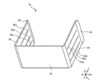
図10は、図4に記載されたクリップ9の構成を示す斜視図である。図11は、図10のクリップ9の構成を示す説明図である。図4、図6、図10及び図11を参照しつつ、クリップ9の構成について説明する。
(クリップ9)
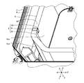
図10に示されるように、クリップ9は、側面視して角張った略U字形状を有している。クリップ9は、クリップ底面部91と、クリップ底面部91の両端それぞれから上方へ延びる2つのクリップ側面部92と、各クリップ側面部92の上端と連続して設けられたクリップ先端部93と、を有している。なお、クリップ先端部93は省略可能である。クリップ9は、例えば板金で構成され、板金を折り曲げることで、連続したクリップ底面部91と、クリップ側面部92と、クリップ先端部93と、が形成されている。
図10に示されるように、クリップ9は、側面視して角張った略U字形状を有している。クリップ9は、クリップ底面部91と、クリップ底面部91の両端それぞれから上方へ延びる2つのクリップ側面部92と、各クリップ側面部92の上端と連続して設けられたクリップ先端部93と、を有している。なお、クリップ先端部93は省略可能である。クリップ9は、例えば板金で構成され、板金を折り曲げることで、連続したクリップ底面部91と、クリップ側面部92と、クリップ先端部93と、が形成されている。
図11に示されるクリップ底面部91の幅すなわち2つのクリップ側面部92の下端の間の距離L1が、図6に示される熱交換器6の気流方向の厚さTと同程度となるようにクリップ9が形成されている。また、図11に示されるように、クリップ底面部91とクリップ側面部92とによりクリップ底面部91の上面側に形成される角度θが90度未満の鋭角となるように、クリップ9が形成されている。よって、図11に示される2つのクリップ側面部92の上端の間の距離L2は、図6に示される熱交換器6の気流方向の厚さTよりも短くなっている。クリップ先端部93は、2つのクリップ先端部93の間の距離L3が、クリップ側面部92とつながる下側から上側に向かって次第に大きくなるように、外側へ傾斜した形状とされる。
図12は、図4の熱交換器6におけるクリップ9装着前の状態を示す分解図である。図13は、図4の熱交換器6におけるクリップ9装着後の状態を示す図である。図12に示されるように、熱交換器6の下方からクリップ9が、クリップ先端部93側から熱交換器6に取り付けられ、図13に示されるように、2つのクリップ側面部92の間に熱交換器6の下端部が配置される。
上述したように2つのクリップ先端部93は外側へ傾斜している。したがって、熱交換器6の下端部を容易に挿入でき、また、熱交換器6の下端6dの縁がクリップ先端部93に押し当てられると2つのクリップ側面部92が開いて熱交換器6の下端部が挿入されるため、熱交換器6に容易にクリップ9が装着できる。
図13に示されるように熱交換器6にクリップ9が装着された状態では、クリップ底面部91の上面は熱交換器6の下端6dと接触し、2つのクリップ側面部92は熱交換器6の上流側面6su及び下流側面6sdとそれぞれ接触する。
上述したように、各クリップ側面部92がクリップ底面部91となす角度θが鋭角とされているので、熱交換器6にクリップ9が取り付けられる際に、熱交換器6の厚みによって2つのクリップ側面部92の上端の間の距離L2(図11)が広げられる。そして、熱交換器6にクリップ9が装着された状態では、広げられた2つのクリップ側面部92に反力が生じることにより、クリップ9が熱交換器6を厚み方向において挟み込む。したがって、熱交換器6における複数の熱交換部の間の厚み方向の開きが抑制され、また、熱交換器6に装着されたクリップ9が外れにくくなる。さらには、複数の熱交換部の厚み方向における開きが抑制されることにより、複数の熱交換部をそれぞれ構成する複数のフィンの、気流方向における隙間をできるだけ小さくし、気流を複数のフィンに沿わせて、熱交換器6の厚み方向へ気流を流し易くできる。
図14は、図10のクリップの変形例を示す図である。図14に示されるように、各クリップ側面部92には、上下方向(矢印Z方向)すなわちクリップ底面部91からクリップ先端部93へ向かう方向に延びるスリット92aが、複数形成されている。このような構成により、図13に示されるように熱交換器6にクリップ9が装着された状態において、熱交換器6のフィンの隙間に流入する、又は熱交換器6のフィンの隙間から流出する空気の流れを、クリップ側面部92が阻害してしまうことを抑制できる。よって、クリップ9が熱交換器6に装着された場合でも、クリップ9による熱交換器6の熱交換性能の低下を抑制することができる。
次に、図6に基づいて、熱交換器取付部品8及びクリップ9の配置について説明する。熱交換器取付部品8は、熱交換器6の第1端部6aから第2端部6bの間において、複数の角部(第1角部6e1、2つの第2角部6e2、及び第3角部6e3)及び複数の辺部(第1辺部6f1~第5辺部6f5)といった部位のいずれかに配置される。
一般に、厚み方向に積層された複数の熱交換部(第1熱交換部61、第2熱交換部62及び第3熱交換部63)を有する熱交換器6では、積層された複数の熱交換部を多角形状に折り曲げる際に、折り曲げ部分すなわち角部の付近において熱交換部同士が離れ易い。このため、熱交換器取付部品8は、熱交換器6において、角部6e、又は辺部6fにおける角部6eの側に配置されることが好ましい。ここで、辺部6fにおける角部6eの側とは、辺部6fの中央よりもその角部6eに近い位置をいう。
また特に、熱交換器6において第1端部6aと第2端部6bとの中間位置に熱交換器取付部品8を配置することにより、熱交換器6において特定の位置で極端に熱交換部の開きが大きくなることを抑制することができる。図6に示される熱交換器6では、開口した角部6e0と対角位置の第1角部6e1、又は第1角部6e1とつながる辺部(第2辺部6f2又は第3辺部6f3)における第1角部6e1の側に、熱交換器取付部品8が配置される。図6に示される例では、熱交換器取付部品8は、熱交換器6において、開口した角部6e0と対角位置にある第1角部6e1とつながった第2辺部6f2における、第1角部6e1の側に配置されている。
クリップ9は、熱交換器6の平面視において、第1端部6aから第2端部6bの間で、熱交換器取付部品8が配置される位置とは異なる位置、好ましくは、複数の角部及び複数の辺部のうち熱交換器取付部品8が配置される部位とは異なる部位に配置される。例えば、図6に示されるように第1角部6e1の付近に熱交換器取付部品8が配置される場合には、第1角部6e1とは異なる角部(2つの第2角部6e2のいずれか、又は第3角部6e3)の付近にクリップ9が配置される。図6に示される例では、第1角部6e1と隣り合う第2角部6e2とつながった第1辺部6f1において第2角部6e2の側に、クリップ9が設けられている。
また、図6に示されるように熱交換器取付部品8及びクリップ9のどちらも辺部に配置される場合には、クリップ9は、熱交換器6において熱交換器取付部品8が配置される辺部(第2辺部6f2)とは異なる辺部(第1辺部6f1)に配置されることが好ましい。このように熱交換器取付部品8に対してクリップ9の位置を決めることにより、熱交換器取付部品8及びクリップ9によって、平面視において熱交換器6の複数の箇所で熱交換部同士の開きが抑制される。
以上のように、実施の形態1において、空気調和機の室内機100は、厚み方向に積層された複数の熱交換部を有する熱交換器6と、熱交換器6を収容する筐体3と、熱交換器取付部品8と、クリップ9と、を備える。熱交換器6は、平面視において多角形状を有し、複数の角部6eと、隣り合う2つの角部6eを接続する直線状の複数の辺部6fと、により形成されている。筐体3は、熱交換器6の上端6uと対向する天板31を有し、熱交換器6を収容する。熱交換器取付部品8は、天板31に固定される固定部83と、複数の熱交換部を厚み方向に挟み込んで支持する支持部81と、を有し、熱交換器6を天板31に対して取り付ける。クリップ9は、熱交換器6の平面視において熱交換器取付部品8の位置とは異なる位置で熱交換器6の下端部に取り付けられ、複数の熱交換部を厚み方向に挟み込む。
これにより、熱交換器取付部品8と熱交換器6に取り付けられるクリップ9とにより、平面視において熱交換器6が複数箇所で厚み方向に挟み込まれ、また、熱交換器取付部品8により熱交換器6が筐体3に固定されるのでネジ固定等の固定箇所を増やす必要がない。したがって、固定箇所の増加といった組立性及びメンテナンス性の悪化を回避しつつ、厚み方向に積層された複数の熱交換部の厚み方向の開き抑制の効果を、従来よりも向上させることができる。
また、熱交換器6は、多角形状の一つの角(角部6e0)が開口している。そして、熱交換器取付部品8は、熱交換器6の複数の角部6eのうち開口した角と対角位置の第1角部6e1、又は複数の辺部6fのうち第1角部6e1とつながる辺部(第2辺部6f2又は第3辺部6f3)において第1角部6e1の側に配置されている。クリップ9は、熱交換器6の複数の角部6eのうち第1角部6e1とは異なる第2角部6e2、又は複数の辺部6fのうち第2角部6e2とつながる辺部(第2辺部6f2又は第1辺部6f1)において第2角部6e2の側に配置されている。
これにより、熱交換部同士の開きが生じ易い熱交換器6の中間位置である角部6e(第1角部6e1)又は当該角部6e(第1角部6e1)の付近において熱交換器6を厚み方向に挟み込むので、熱交換部同士の開きを効果的に抑制することができる。
第2角部6e2は、熱交換器6の複数の角部6eのうち第1角部6e1と隣り合う角部である。これにより、隣り合う角部において二段階で熱交換器6が厚み方向に挟み込まれるので、熱交換器6における第1端部6aから第2端部6bまでの間の区間において特に熱交換部同士の開きが生じ易い場所等に設けて、集中的に開きを抑制する構成とできる。
熱交換器取付部品8とクリップ9とは、熱交換器6において異なる辺部(例えば、第2辺部6f2と第1辺部6f1)に配置されている。これにより、角部が介在する異なる辺部でそれぞれ生じる熱交換部同士の開きが、熱交換器取付部品8とクリップ9とにより、効率的に抑制できる。
クリップ9は、熱交換器6の下端6dと対向するクリップ底面部91と、各々がクリップ底面部91と連続して形成され、熱交換器6における厚み方向の両側の側面(上流側面6su及び下流側面6sd)に接触する2つのクリップ側面部92と、を有する。これにより、熱交換器6への脱着が容易にでき、且つ製作が容易なクリップ9が得られる。
クリップ側面部92は、クリップ底面部91となす角度θが鋭角となるように傾斜している。これにより、熱交換器6にクリップ9が装着された状態では、装着時に熱交換器6の厚みにより2つのクリップ側面部92が広げられることで生じた反力により、2つのクリップ側面部92で熱交換器6を厚み方向に挟み込むことができる。したがって、熱交換器6における複数の熱交換部の間の厚み方向の開きが抑制され、また、熱交換器6に取り付けられたクリップ9が外れにくくなる。
クリップ9の先端部(クリップ先端部93)は、外側に傾斜している。これにより、熱交換器6の下端6dが容易に挿入でき、また、熱交換器6の下端6dをクリップ先端部93に押し当てることで容易に熱交換器6にクリップ9が装着できる。
なお、実施の形態は上述した実施の形態1に限定されず、適宜、変形、又は省略が可能である。例えば、熱交換器6の形状及び熱交換器6を構成する部位の組み合わせは上述したものに限定されない。また熱交換器取付部品8の形状は、図9に示される形状に限定されない。熱交換器取付部品8は、筐体3に固定され、熱交換器6を厚み方向に挟み込んで支持する構成であればどのような形状とされてもよい。またクリップ9の形状は、図10~11に示されるものに限定されない。クリップ9は、熱交換器6を厚み方向に挟み込み、熱交換器6に装着される形状であればどのような形状とされてもよい。またクリップ9が2つ設けられる場合について説明したが、クリップ9の数はこれに限定されない。クリップ9は、熱交換器6に1つのみ設けられてもよく、3つ以上設けられてもよい。クリップ9の数は、例えば、熱交換器6を構成する角部の数等に応じて、適宜決定すればよい。
1 化粧パネル、1a 吸込口、1b 吹出口、2 装置本体、3 筐体、3a モータ設置溝、3b 凹部、3c バルブ取付口、4 断熱材、5 送風機、6 熱交換器、6a 第1端部、6b 第2端部、6d 下端、6e、6e0 角部、6e1 第1角部、6e2 第2角部、6e3 第3角部、6f 辺部、6f1 第1辺部、6f2 第2辺部、6f3 第3辺部、6f4 第4辺部、6f5 第5辺部、6sd 下流側面、6su 上流側面、6u 上端、7 露受け部品、7a 中央開口部、7b 側方開口部、8 熱交換器取付部品、9 クリップ、10 端部固定部品、11 第1端部固定部品、11a 連結部、11b 固定部、12 第2端部固定部品、12a 連結部、12b 固定部、13a、13b 配管、14a、14b、14c、14d、14e U字管、31 天板、32 右側板、33 前側板、34 左側板、35 後側板、36 バルブ取付側板、37 接続板、51 羽根、61 第1熱交換部、62 第2熱交換部、63 第3熱交換部、81 支持部、81a 支持面、81b 規制面、82 接続部、83 固定部、83a 穴、91 クリップ底面部、92 クリップ側面部、92a スリット、93 クリップ先端部、100 室内機、111、112 側面部、121、122 側面部、L1、L2、L3 距離、T 厚さ、θ 角度。
Claims (7)
- 厚み方向に積層された複数の熱交換部を有する熱交換器であって、平面視において多角形状を有し、複数の角部と、隣り合う2つの角部を接続する直線状の複数の辺部と、により形成された前記熱交換器と、
前記熱交換器の上端と対向する天板を有し、前記熱交換器を収容する筐体と、
前記天板に固定される固定部と、前記複数の熱交換部を厚み方向に挟み込んで支持する支持部と、を有し、前記熱交換器を前記天板に対して取り付ける熱交換器取付部品と、
前記熱交換器の平面視において前記熱交換器取付部品の位置とは異なる位置で前記熱交換器の下端部に取り付けられ、前記複数の熱交換部を厚み方向に挟み込むクリップと、を備えた
空気調和機の室内機。 - 前記熱交換器は、前記多角形状の一つの角が開口しており、
前記熱交換器取付部品は、前記熱交換器の前記複数の角部のうち開口した前記角と対角位置の第1角部、又は前記複数の辺部のうち前記第1角部とつながる辺部において前記第1角部の側に配置され、
前記クリップは、前記熱交換器の前記複数の角部のうち前記第1角部とは異なる第2角部、又は前記複数の辺部のうち前記第2角部とつながる辺部において前記第2角部の側に配置されている
請求項1に記載の空気調和機の室内機。 - 前記第2角部は、前記熱交換器の前記複数の角部のうち前記第1角部と隣り合う角部である
請求項2に記載の空気調和機の室内機。 - 前記熱交換器取付部品と前記クリップとは、前記熱交換器において異なる辺部に配置されている
請求項1~3のいずれか一項に記載の空気調和機の室内機。 - 前記クリップは、
前記熱交換器の下端と対向するクリップ底面部と、
各々が前記クリップ底面部と連続して形成され、前記熱交換器における前記厚み方向の両側の側面に接触する2つのクリップ側面部と、を有する
請求項1~4のいずれか一項に記載の空気調和機の室内機。 - 前記クリップ側面部は、前記クリップ底面部となす角度が鋭角となるように傾斜している
請求項5に記載の空気調和機の室内機。 - 前記クリップの先端部は、外側に傾斜している
請求項5又は6に記載の空気調和機の室内機。
Priority Applications (2)
| Application Number | Priority Date | Filing Date | Title |
|---|---|---|---|
| PCT/JP2020/044263 WO2022113283A1 (ja) | 2020-11-27 | 2020-11-27 | 空気調和機の室内機 |
| JP2022564946A JP7374345B2 (ja) | 2020-11-27 | 2020-11-27 | 空気調和機の室内機 |
Applications Claiming Priority (1)
| Application Number | Priority Date | Filing Date | Title |
|---|---|---|---|
| PCT/JP2020/044263 WO2022113283A1 (ja) | 2020-11-27 | 2020-11-27 | 空気調和機の室内機 |
Publications (1)
| Publication Number | Publication Date |
|---|---|
| WO2022113283A1 true WO2022113283A1 (ja) | 2022-06-02 |
Family
ID=81755408
Family Applications (1)
| Application Number | Title | Priority Date | Filing Date |
|---|---|---|---|
| PCT/JP2020/044263 Ceased WO2022113283A1 (ja) | 2020-11-27 | 2020-11-27 | 空気調和機の室内機 |
Country Status (2)
| Country | Link |
|---|---|
| JP (1) | JP7374345B2 (ja) |
| WO (1) | WO2022113283A1 (ja) |
Citations (3)
| Publication number | Priority date | Publication date | Assignee | Title |
|---|---|---|---|---|
| JPH07167451A (ja) * | 1993-12-13 | 1995-07-04 | Mitsubishi Heavy Ind Ltd | 天井埋込形空気調和機 |
| JP2002081679A (ja) * | 2001-08-02 | 2002-03-22 | Toshiba Kyaria Kk | 空気調和機 |
| JP2006226595A (ja) * | 2005-02-17 | 2006-08-31 | Matsushita Electric Ind Co Ltd | 空気調和機 |
-
2020
- 2020-11-27 WO PCT/JP2020/044263 patent/WO2022113283A1/ja not_active Ceased
- 2020-11-27 JP JP2022564946A patent/JP7374345B2/ja active Active
Patent Citations (3)
| Publication number | Priority date | Publication date | Assignee | Title |
|---|---|---|---|---|
| JPH07167451A (ja) * | 1993-12-13 | 1995-07-04 | Mitsubishi Heavy Ind Ltd | 天井埋込形空気調和機 |
| JP2002081679A (ja) * | 2001-08-02 | 2002-03-22 | Toshiba Kyaria Kk | 空気調和機 |
| JP2006226595A (ja) * | 2005-02-17 | 2006-08-31 | Matsushita Electric Ind Co Ltd | 空気調和機 |
Also Published As
| Publication number | Publication date |
|---|---|
| JPWO2022113283A1 (ja) | 2022-06-02 |
| JP7374345B2 (ja) | 2023-11-06 |
Similar Documents
| Publication | Publication Date | Title |
|---|---|---|
| KR101595639B1 (ko) | 공기 조화 장치의 실외기 | |
| JP5447580B2 (ja) | 空調機の室外機 | |
| JP6488886B2 (ja) | ダクト型空気調和機 | |
| EP2402669B1 (en) | Built-in type air conditioner | |
| JP5761097B2 (ja) | 空気調和装置の室内機 | |
| US20200166278A1 (en) | Heat exchanger | |
| WO2013146006A1 (ja) | 空気調和装置の熱交換器及び空気調和装置 | |
| WO2013080682A1 (ja) | 空気調和装置の室外機 | |
| JP2004156800A (ja) | 冷凍装置の室外ユニット | |
| JP2000039185A (ja) | 空気調和機 | |
| JP2000046375A (ja) | 室外ユニット及び空気調和機 | |
| JP7374345B2 (ja) | 空気調和機の室内機 | |
| JP6833066B1 (ja) | 空気調和機 | |
| JP2014228223A (ja) | 空気調和機 | |
| JP2013076521A (ja) | 空気調和装置の室外機 | |
| JP2004218905A (ja) | 分離型空気調和装置 | |
| JP7482439B2 (ja) | 空気調和装置 | |
| JP5195042B2 (ja) | 空調室内機 | |
| JP7137092B2 (ja) | 熱交換器 | |
| JP2019143855A (ja) | 熱交換装置 | |
| JPWO2019116838A1 (ja) | 熱交換ユニット及びこれを搭載する空気調和装置 | |
| JP2004156801A (ja) | 冷凍装置の室外ユニット | |
| JP2013130330A (ja) | 空気調和装置、及び、熱交換器 | |
| JP2605186B2 (ja) | 空気調和機 | |
| JP3998030B2 (ja) | 天井設置型空気調和装置 |
Legal Events
| Date | Code | Title | Description |
|---|---|---|---|
| 121 | Ep: the epo has been informed by wipo that ep was designated in this application |
Ref document number: 20963547 Country of ref document: EP Kind code of ref document: A1 |
|
| ENP | Entry into the national phase |
Ref document number: 2022564946 Country of ref document: JP Kind code of ref document: A |
|
| NENP | Non-entry into the national phase |
Ref country code: DE |
|
| 122 | Ep: pct application non-entry in european phase |
Ref document number: 20963547 Country of ref document: EP Kind code of ref document: A1 |