WO2022107855A1 - 画像処理システムおよび画像処理装置 - Google Patents
画像処理システムおよび画像処理装置 Download PDFInfo
- Publication number
- WO2022107855A1 WO2022107855A1 PCT/JP2021/042467 JP2021042467W WO2022107855A1 WO 2022107855 A1 WO2022107855 A1 WO 2022107855A1 JP 2021042467 W JP2021042467 W JP 2021042467W WO 2022107855 A1 WO2022107855 A1 WO 2022107855A1
- Authority
- WO
- WIPO (PCT)
- Prior art keywords
- region
- image processing
- change
- attention
- output
- Prior art date
- Legal status (The legal status is an assumption and is not a legal conclusion. Google has not performed a legal analysis and makes no representation as to the accuracy of the status listed.)
- Ceased
Links
Images





Classifications
-
- G—PHYSICS
- G01—MEASURING; TESTING
- G01T—MEASUREMENT OF NUCLEAR OR X-RADIATION
- G01T1/00—Measuring X-radiation, gamma radiation, corpuscular radiation, or cosmic radiation
- G01T1/16—Measuring radiation intensity
- G01T1/20—Measuring radiation intensity with scintillation detectors
- G01T1/2012—Measuring radiation intensity with scintillation detectors using stimulable phosphors, e.g. stimulable phosphor sheets
- G01T1/2014—Reading out of stimulable sheets, e.g. latent image
-
- A—HUMAN NECESSITIES
- A61—MEDICAL OR VETERINARY SCIENCE; HYGIENE
- A61B—DIAGNOSIS; SURGERY; IDENTIFICATION
- A61B6/00—Apparatus or devices for radiation diagnosis; Apparatus or devices for radiation diagnosis combined with radiation therapy equipment
- A61B6/50—Apparatus or devices for radiation diagnosis; Apparatus or devices for radiation diagnosis combined with radiation therapy equipment specially adapted for specific body parts; specially adapted for specific clinical applications
- A61B6/51—Apparatus or devices for radiation diagnosis; Apparatus or devices for radiation diagnosis combined with radiation therapy equipment specially adapted for specific body parts; specially adapted for specific clinical applications for dentistry
-
- A—HUMAN NECESSITIES
- A61—MEDICAL OR VETERINARY SCIENCE; HYGIENE
- A61B—DIAGNOSIS; SURGERY; IDENTIFICATION
- A61B6/00—Apparatus or devices for radiation diagnosis; Apparatus or devices for radiation diagnosis combined with radiation therapy equipment
- A61B6/52—Devices using data or image processing specially adapted for radiation diagnosis
- A61B6/5258—Devices using data or image processing specially adapted for radiation diagnosis involving detection or reduction of artifacts or noise
Definitions
- the present disclosure particularly relates to an image processing and an image processing apparatus that produces an X-ray image by processing a read signal read from an image plate on which an X-ray photographed image is recorded.
- IP imaging plate
- the reading device irradiates the imaging plate with a laser beam, detects the brilliant emission excited by the irradiation of the laser beam, performs processing such as logarithmic conversion amplification and A / D conversion, and outputs a digital signal.
- the read signal obtained by detecting the emission emission is subjected to processing such as logarithmic conversion amplification and A / D conversion.
- processing such as logarithmic conversion amplification and A / D conversion.
- a sleepy image is generated depending on the purpose of observation.
- a drowsy image is a vague (blurred) image in which the contrast at the site to be observed is not clear.
- the present disclosure describes an image processing system capable of improving the contrast in a portion of the obtained X-ray image to be observed.
- One aspect of the present disclosure is an image processing system that processes a read signal read from an image plate on which an X-ray photographed image is recorded to generate an X-ray image, with respect to the entire output range included in the read signal. Signal processing is performed so that the degree of change in shading with respect to a part of the attention area according to the purpose of observation is larger than the degree of change in shading with respect to the non-attention area other than the attention area.
- the degree of change in shading is large only in a part of the attention area according to the purpose of observation in the total output area included in the read signal. Therefore, in the obtained X-ray image, the contrast at the portion to be observed is improved.
- the above image processing system may perform signal processing by logarithmic transformation.
- the logarithmic transformation makes it easier to see the change in shade, for example, even when the dose intensity is low. As a result, an X-ray image that is clinically easy to handle can be obtained.
- the attention region and the non-attention region may be set so that the dose intensity region corresponding to the attention region exists on the lower dose side than the dose intensity region corresponding to the non-attention region.
- the contrast on the low dose side is emphasized at the expense of the contrast on the high dose side (non-attention region). This makes it possible to achieve high contrast in a region where the dose intensity is low.
- the attention region and the non-attention region may be set so that the dose intensity region corresponding to the attention region exists on the higher dose side than the dose intensity region corresponding to the non-attention region.
- the contrast on the high dose side is emphasized at the expense of the contrast on the low dose side (non-attention region). This makes it possible to achieve high contrast in a region where the dose intensity is high.
- the non-attention region is from the first non-attention region having a dose intensity region existing on the lower dose side than the dose intensity region corresponding to the attention region and the dose intensity region corresponding to the attention region.
- the attention region and the non-attention region may be set so as to include the second non-attention region having the dose intensity region existing on the high dose side. In this case, a region of interest corresponding to a desired dose intensity region is set, and contrast in the region of interest is emphasized.
- the above image processing system may perform signal processing so that the non-attention region is represented by a constant density by eliminating the degree of change in the shade of the non-attention region. In this case, it is possible to further sharpen the attention area and the non-attention area.
- the image portion corresponding to the non-focused area is an image having uniform density and having no contrast
- the image portion corresponding to the focused area is an image having a clearer contrast with a large change in density.
- the above image processing system may perform signal processing on an analog signal before analog-to-digital conversion.
- signal processing is performed on a digital signal, small differences in output values can disappear.
- the difference of the analog signal can be reflected in the shading in the X-ray image.
- Another aspect of the present disclosure is an image processing system that processes a detection signal by radiography to generate an X-ray image, and is a part of the entire output range included in the detection signal according to the purpose of observation.
- the signal processing is performed so that the degree of change in the light and shade regarding the attention area is larger than the degree of change in the light and shade regarding the non-attention area other than the attention area.
- the degree of change in shading is large only in a part of the attention area according to the purpose of observation in the total output area included in the detection signal. Therefore, in the obtained X-ray image, the contrast at the portion to be observed is improved.
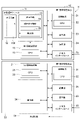
- FIG. 1 is a diagram showing a schematic configuration of an image processing system according to an embodiment of the present disclosure.
- FIG. 2 is a diagram showing a more specific configuration of the image processing system of FIG.
- FIG. 3 is a block diagram showing a configuration example in the image processing unit (image processing device).
- FIG. 4 is a flow chart of basic processing executed in the image processing system.
- FIG. 5 is a flow chart showing an example of processing executed in the image processing system.
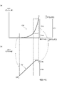
- FIG. 6A is a diagram showing the characteristics of an analog signal
- FIG. 6B is a diagram showing the degree of change in the output after signal processing.
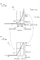
- FIG. 7A is a diagram showing the characteristics of an analog signal
- FIG. 7B is a diagram showing the degree of change in the output after signal processing.
- FIG. 1 is a diagram showing a schematic configuration of an image processing system according to an embodiment of the present disclosure.
- FIG. 2 is a diagram showing a more specific configuration of the image processing system of FIG.
- FIG. 3 is a block
- FIG. 8 is a diagram showing an aluminum staircase phantom having a plurality of steps of thickness.
- 9 (a) and 9 (b) are diagrams showing the degree of change in shading when the signal processing of the present disclosure is not performed (without correction).
- 10 (a) and 10 (b) are diagrams showing the degree of change in shading when a region of interest is set on the low dose side (high X-ray absorption region), and
- FIG. 10 (c) is a diagram showing the degree of change in shading in that case. It is a figure which shows the example of the X-ray image in the dental practice of.
- 11 (a) and 11 (b) are diagrams showing the degree of change in shading when a region of interest is set on the high dose side (X-ray low absorption region), and
- FIG. 11 (c) is a diagram showing that case. It is a figure which shows the example of the X-ray image in the dental practice of.
- FIG. 12 (a) is a diagram showing changes in each step when there is no correction
- FIG. 12 (b) is a diagram showing changes in each step when there is correction.
- FIG. 13 is a block diagram showing another configuration example in the image processing unit (image processing device).
- 14 (a) is a diagram showing the characteristics of the analog signal
- FIG. 14 (b) is a diagram showing the degree of change in the output after signal processing according to the configuration example of FIG. 13.
- FIG. 15 is a flow chart showing another example of processing executed in the image processing system.
- 16 (a) is a diagram showing an example of an object
- FIG. 16 (b) and 16 (c) are diagrams showing an example of intensity detection.
- FIG. 17A is a diagram showing the characteristics of the analog signal
- FIG. 17B is a diagram showing the degree of change in the output after signal processing according to the configuration example of FIG.
- FIG. 18A is a diagram showing the characteristics of the analog signal
- FIG. 18B is a diagram showing the degree of change in the output after signal processing according to the configuration example of FIG.
- the image processing system S of the present embodiment is used, for example, for X-ray photography in dental practice.
- an image plate 100 is installed in the oral cavity of a patient, and X-ray photography is performed in the oral cavity.
- An X-ray photographed image is recorded on the image plate 100. Since the image plate is sometimes called an imaging plate, it can also be called an imaging plate.
- the image processing system S is a system that generates an X-ray image by processing a read signal read from an image plate 100 (see FIG. 2) in which an X-ray photographed image is recorded.
- the image processing system S includes an IP excitation module 11, an image processing unit 2, a main control unit 20, an operation unit (physical interface) 4, and a display unit (display) 3.
- the IP excitation module 11 irradiates the image plate 100 with excitation light, scans the image plate 100, and detects the emission of emission generated in the image plate 100.
- the IP excitation module 11 has, for example, a photodiode array, an amplifier, and the like, and outputs a read signal of an X-ray photographed image based on the obtained luminance information.
- the IP excitation module 11 As the IP excitation module 11, a known configuration can be adopted.
- the IP excitation module 11 may be configured as a set of a light source for excitation light and a scanner for emission emission, and may be expressed as a light source / scanner 11.
- the main control unit 20 has a CPU 20a and controls each unit of the image processing system S.
- the operation unit 4 has an operation button, a touch panel display, or the like, and receives an operation by the operator.
- the operation unit 4 outputs a signal according to the input operation content to the main control unit 20.
- the image processing unit 2 has a CPU 2a and is controlled by the main control unit 20 to perform various operations related to image processing.
- the image processing unit 2 performs analog-digital conversion, synthesis processing, and the like on the read signal to generate an X-ray image.
- the main control unit 20 causes the display unit 3 to display an X-ray image.
- the image processing unit 2 may also serve as the main control unit 20.
- the main control unit 20 may be composed of a circuit, or may be expressed as a main control circuit 20.
- the image processing unit 2 may be configured by a circuit, or may be expressed as a sub image processing circuit 2.
- the image processing system S may be integrally provided with the above-mentioned configuration.
- the IP excitation module 11 and a part of the image processing unit 2 are integrated, and the other part of the image processing unit 2 and the display unit 3 are integrated. They may be integrated and connected communicably by wiring, network, or the like (see FIG. 2).
- the operation unit 4 may be provided on both sides.
- the image processing system S may be composed of a circuit.
- the image processing system S may be expressed as an image processing circuit S.
- Each component of the image processing system S may be integrated and incorporated, for example, inside a case or a housing.
- the image processing system S is configured as an "image processing device". That is, the image processing system S may be expressed as an image processing device S.
- FIG. 2 a specific configuration example of the image processing system S will be described.
- the image plate 100 is abbreviated as IP100.
- the image processing system S shown in FIG. 2 includes a first image processing device 10 and a second image processing device 30.
- the first image processing device 10 and the second image processing device 30 are connected by wiring, a network, or the like, and can communicate with each other by the input / output interfaces 25 and 35.
- the first image processing device 10 includes an IP excitation module 11, a first image processing unit 18 including a CPU 19, a main control unit 21 including a CPU 22, a display unit 23, an operation unit 24, and an input / output interface 25.
- the second image processing device 30 includes a second image processing unit 28 including a CPU 29, a main control unit 31 including a CPU 32, a storage unit (memory) 36, a display unit (display) 33, and an operation unit (physical interface). It has 34 and an input / output interface 35.
- the display unit 23 and the display unit 33 correspond to the display unit 3 in FIG.
- the operation unit 24 and the operation unit 34 correspond to the operation unit 4 in FIG.
- the first image processing device 10 may be configured by a circuit, or may be expressed as a first image processing circuit 10.
- the second image processing device 30 may be configured by a circuit, or may be expressed as a second image processing circuit 30.
- the first image processing unit 18 may be configured by a circuit, or may be expressed as a first sub-image processing circuit 18.
- the second image processing unit 28 may be configured by a circuit, or may be expressed as a second sub-image processing circuit 28.
- the main control unit 21 may be composed of a circuit, or may be expressed as a first main control circuit 21.
- the main control unit 31 may be composed of a circuit, or may be expressed as a second main control circuit 31.
- the CPU 19 may be expressed as a first image processing processor 19.
- the CPU 22 may be expressed as a first main control processor 22.
- the CPU 29 may be expressed as a second image processing processor 29.
- the CPU 32 may be expressed as a second main control processor 32.
- the IP excitation module 11 receives the IP receiving unit 12 that accepts the IP100, the excitation light irradiation unit (excitation light light source) 14 that irradiates the IP100 in the IP acceptance unit 12 with excitation light, and the light generated by the excitation light irradiation unit 14.
- the light receiving unit 16 outputs a read signal of the X-ray photographed image to the first image processing unit 18.
- the first image processing unit 18 and the second image processing unit 28 correspond to the image processing unit 2 in FIG.
- the first image processing unit 18 and the second image processing unit 28 execute a predetermined image processing step. The processing performed by the first image processing unit 18 and the second image processing unit 28 will be described later.
- the second image processing device 30 causes the display unit 33 to display the X-ray image output from the second image processing unit 28, and outputs the X-ray image to the external device 39.
- the first image processing unit 18 of the present embodiment has an analog-to-digital conversion unit 40 that performs analog-to-digital conversion on the read signal output from the IP excitation module 11.
- the first image processing unit 18 includes the analog-to-digital conversion unit 40 to perform signal processing on the analog signal before the analog-to-digital conversion.
- the analog-to-digital conversion unit 40 has a part of the attention areas RV11 and RP11 (R1) according to the purpose of observation and non-attention areas other than the attention area R1 for the entire output area included in the read signal.
- the regions RV2a, RP2a, RV2b, and RP2b are set (see FIG. 6A).
- the non-attention regions RV2a and RP2a are dose intensity regions existing on the lower dose side than the dose intensity region corresponding to the attention region R1, and the non-attention regions RV2b and RP2b are higher doses than the dose intensity region corresponding to the attention region R1. It is the dose intensity range existing on the side.
- the first non-attention region RV2a and RP2a having a lower output value are determined to be represented by a uniform adjusted output value (for example, white), and the second non-attention region has a higher output value.
- the non-attention areas RV2b and RP2b can be determined so as to be represented by a uniform adjusted output value (for example, black).
- a process for optimizing the contrast is performed (see FIG. 6 (b)).
- the first non-attention region RP2a may be the offset value OF.
- the original output pattern for the dose without the output adjustment processing according to the present configuration is called the original output pattern OR, and this original output pattern OR is shown by the original output pattern line ORL on the graph as shown in FIG. 6A.
- the image processing unit 2 performs signal processing on the analog signal.
- the output pattern for the dose to be adjusted after signal processing is called an adjusted output pattern AJ, and this adjusted output pattern AJ is shown by the adjusted output pattern line AJL on the graph as shown in FIG. 6 (b).
- In the original output pattern OR in the low dose region, there are many regions where the change in the output value is small with respect to the change in the dose value, and in the high dose region, there are many regions where the change in the output value is sharp with respect to the change in the dose value. Is done.
- signal processing is performed so that the degree of change is large (steep) in the adjusted output pattern AJ in the region where the change in the output value is small with respect to the change in the dose value of the original output pattern OR, that is, in the region where the degree of change in shading is small. It is conceivable to do.
- the degree of change is small (becomes gradual) in the adjusted output pattern AJ in a region where the change in the output value is steep with respect to the change in the dose value of the original output pattern OR, that is, in a region where the degree of change in shading is steep.
- FIG. 6 (b) shows an example of a linear adjustment pattern subjected to these processes.
- the upper limit value RH and the lower limit value RL of the adjusted output pattern AJ can be appropriately determined, but the upper limit value RH and the lower limit value RL are adapted to the minimum value and the maximum value of the attention area R1 in the original output pattern OR as shown in the figure. May be good.
- FIG. 7B shows an example of such an adjustment process.
- the range of the attention region RV12 and RP12 (R1) is limited to the region on the lower dose side than the example of R1 shown in FIG.
- the analog-to-digital conversion unit 40 performs signal processing so that the degree of change in light and shade with respect to the attention area is larger (becomes steep) than the degree of change in light and shade with respect to the non-attention area R2 (RV2c, RP2c, RV2d, RP2d).
- the degree of change in shade in the non-focused area is slower than the degree of change in shade in the focused area.
- the upper limit value RH and the lower limit value RL of the adjustment output pattern AJ can be appropriately determined, but the upper limit value RH and the lower limit value RL are matched with the width of the upper limit value and the lower limit value of the adjustment output pattern AJ in FIG. 6 as shown in the figure. May be good. The details of the adjustment process will be described later.
- the analog-to-digital converter 40 includes a logarithmic converter 41 and a first analog-to-digital converter 42.
- the logarithmic converter 41 performs logarithmic conversion on the read signal.
- the signal processing for making the degree of change in shading steep or gradual with respect to the above-mentioned attention region and non-attention region is performed before the analog-digital conversion by the analog-digital converter 42.
- the signal processing may be performed before the logarithmic conversion by the logarithmic converter 41 or may be performed after the logarithmic conversion.
- the second image processing unit 28 includes a composition processing unit 50.
- the compositing processing unit 50 inputs the digital signal output from the first analog-to-digital converter 42, and outputs the X-ray image data (data of the compositing image P).
- the synthesis processing unit 50 may be configured by a circuit, or may be expressed as a synthesis processing circuit 50.
- the image processing unit 2 acquires scanned image data (read signal) from the IP excitation module 11 (step S020).
- the image processing unit 2 generates and displays a default image (step S030).
- the operation unit 4 is operated, so that the main control unit 20 accepts the operation (step S040).
- the main control unit 20 reads the process (step S060).
- the image processing unit 2 executes image processing based on the acquired scanned image data (step S070).
- the image processing unit 2 generates an X-ray image, and the main control unit 20 causes the display unit 3 to display the X-ray image (step S080).
- the main control unit 20 accepts another operation (step S090). If there is a reception for another operation, the main control unit 20 returns to the process of step S060.
- the scanned image data may be stored in the storage unit 36, and the scanned image data may be acquired from the storage unit 36 when returning to the process of step 060. If no other operation is accepted, the image processing unit 2 ends a series of processes (step S100).
- the processing performed by the image processing unit 2 is performed by the first image processing unit 18 and / or the second image processing unit 28.
- the processing performed by the main control unit 20 is performed by the main control unit 21 and / or the main control unit 31.
- an aluminum staircase phantom AL that imitates an object for radiography (for example, a patient's tooth or oral cavity) can be provided.
- the aluminum staircase phantom AL for example, aluminum plates are stacked to form a staircase so that the thickness of aluminum changes in 10 steps including zero aluminum. In the thick aluminum part, more X-rays are absorbed and a smaller X-ray transmission dose is obtained. In areas where the aluminum is thin, less X-rays are absorbed and larger X-ray transmission doses are obtained.
- a low dose side region RA X-ray high absorption region
- RB X-ray low absorption region
- the dose intensity gradually increases as the thickness decreases. There is a tendency to increase. If the thickness changes continuously rather than stepwise, the dose intensity can change linearly with the thickness. In this way, in normal image processing (stepwise processing), there is an even difference in brightness over the entire output range. In the present embodiment, the difference between light and dark can be made by focusing on the area of interest of interest.
- the image processing unit 2 executes different processing according to the content of the operation input in step S040.
- the main control unit 20 determines what operation was accepted in step S040 (step S050).
- the types of operations that can be accepted may be a first designation or a second designation.
- the first designation is an operation in which, for example, a perio, an end, a caries, or the like is designated as a part of the attention area according to the purpose of observation.
- the second designation is an operation in which, for example, anterior teeth or molars are designated as a part of the attention area according to the purpose of observation.
- the main control unit 20 reads out the first process (step S060-1).
- the image processing unit 2 executes image processing suitable for the first processing (step S070-1).
- the image processing unit 2 sets the attention region and the non-attention region so that the dose intensity region corresponding to the attention region exists on the lower dose side than the dose intensity region corresponding to the non-attention region.
- the image processing unit 2 sets, for example, a region having an output of less than 60 shown in FIG. 9, that is, a low-dose side region RA (X-ray high absorption region) shown in FIGS. 8 and 10 as a region of interest.
- the image processing unit 2 sets a region having an output of 60 or more shown in FIG.
- the image processing unit 2 may perform signal processing so that the non-attention region is represented by a constant density by eliminating the degree of change in the shade of the non-attention region. That is, the image processing unit 2 may perform logarithmic conversion and analog-digital conversion only on the analog signal in the region of interest.
- the above image processing is executed, for example, by the analog-digital conversion unit 40 of the first image processing unit 18.
- the image processing unit 2 generates an X-ray image suitable for the first processing, and the main control unit 20 causes the display unit 3 to display the X-ray image (step S080-1).
- the main control unit 20 accepts another operation (step S090-1). If there is a reception for another operation, the main control unit 20 returns to the determination process in step S050.
- the degree of change in the shade of the low-dose side region RA is related to the region other than the low-dose side region RA.
- Signal processing is performed so that the degree of change in shading is greater than the degree of change (see FIG. 10 (b)).
- the degree of change in shading with respect to the low-dose side region RA is the low-dose side region RA. It is steeper than the degree of change in shading in areas other than the above.
- the output (pixel value) is represented by a constant density.
- the region on the high dose side which is a non-attention region, is represented by a uniform black color in the X-ray image.
- the dose intensity (value expressed in the unit mGy) obtained as an analog signal is not evenly divided by a limited number of bits (65,535 for 16 bits), but a low dose, which is a region of interest. Since the dose intensity in the side region RA is evenly divided, the contrast resolution of the desired portion is optimized according to the purpose of observation. For example, as shown in FIG. 10 (c), such image processing is suitable for observing the cervical region Y, and instead of obscuring the details of the high dose side region such as the periodontal region, the tooth Caries and the like in the neck Y can be easily found.
- the main control unit 20 reads out the second process (step S060-2).
- the image processing unit 2 executes image processing suitable for the second processing (step S070-2).
- the image processing unit 2 sets the attention region and the non-attention region so that the dose intensity region corresponding to the attention region exists on the higher dose side than the dose intensity region corresponding to the non-attention region.
- the image processing unit 2 sets, for example, a region having an output of 40 or more shown in FIG. 9, that is, a high-dose side region RB (X-ray low absorption region) shown in FIGS. 8 and 10 as a region of interest.
- the image processing unit 2 sets a region having an output of less than 40 shown in FIG.
- the image processing unit 2 may perform signal processing so that the non-attention region is represented by a constant density by eliminating the degree of change in the shade of the non-attention region. That is, the image processing unit 2 may perform logarithmic conversion and analog-digital conversion only on the analog signal in the region of interest.
- the above image processing is executed, for example, by the analog-digital conversion unit 40 of the first image processing unit 18.
- the image processing unit 2 generates an X-ray image suitable for the second processing, and the main control unit 20 causes the display unit 3 to display the X-ray image (step S080-2).
- the main control unit 20 accepts another operation (step S090-2). If there is a reception for another operation, the main control unit 20 returns to the determination process in step S050.
- the degree of change in the shade of the high-dose side region RB is related to the region other than the high-dose side region RB.
- Signal processing is performed so that the degree of change in shading is greater than the degree of change (see FIG. 11B).
- the degree of change in shading with respect to the high dose side region RB is the high dose side region RB. It is steeper than the degree of change in shading in areas other than the above.
- the output (pixel value) is represented by a constant density.
- the low-dose side region which is a non-attention region
- the low-dose side region is represented by a uniform white color in the X-ray image.
- the dose intensity (value expressed in the unit mGy) obtained as an analog signal is not evenly divided by a limited number of bits (65,535 for 16 bits), but a high dose, which is a region of interest.
- the contrast resolution of the desired portion is optimized according to the purpose of observation. For example, as shown in FIG. 11 (c), such image processing is suitable for observation around the apex Z, and instead the details of the low dose side region, such as the cervical region, are obscured. Apical lesions and the like around the apex Z can be easily found.
- the signal processing by the first image processing unit 18 makes the degree of change in shading in the region of interest steep in the X-ray image.
- the degree of change in shade as shown in FIG. 12 (b) is sharp with respect to the degree of uniform change in shade as shown in FIG. 12 (a), which is shown by taking the aluminum staircase phantom AL as an example. It is easy to understand from.
- the degree of change in shading is large only in a part of the attention area according to the purpose of observation in the total output area included in the read signal. Therefore, in the obtained X-ray image, the contrast at the portion to be observed is improved.
- the image processing system S may perform signal processing by logarithmic transformation.
- the logarithmic conversion makes it easy to understand the change in shade even when the dose intensity is low, for example, in the low-dose side region RA. As a result, an X-ray image that is clinically easy to handle can be obtained.
- the attention region and the non-attention region can be set so that the dose intensity region corresponding to the attention region exists on the lower dose side than the dose intensity region corresponding to the non-attention region.
- the contrast on the low dose side is emphasized at the expense of the contrast on the high dose side (non-attention region). This makes it possible to achieve high contrast in a region where the dose intensity is low.
- the attention region and the non-attention region can be set so that the dose intensity region corresponding to the attention region exists on the higher dose side than the dose intensity region corresponding to the non-attention region.
- the contrast on the high dose side is emphasized at the expense of the contrast on the low dose side (non-attention region). This makes it possible to achieve high contrast in a region where the dose intensity is high.
- the image processing system S performs signal processing so that the non-attention region is represented by a constant density by eliminating the degree of change in the shade of the non-attention region. As a result, it is possible to further sharpen the attention area and the non-attention area.
- the image portion corresponding to the non-focused area is an image having uniform color (density) and no contrast
- the image portion corresponding to the focused area is an image having a clearer contrast with a large change in density.
- the image processing system S performs signal processing on the analog signal before analog-to-digital conversion.
- signal processing is performed on a digital signal, small differences in output values can disappear.
- signal processing is performed on the region of interest (prior to) before analog-to-digital conversion, it is possible to reflect the fine differences of the analog signal in the shading in the X-ray image.
- FIG. 13 is a block diagram showing another configuration example in the image processing unit.
- a distributor 17 a first analog-to-digital converter 40A including a logarithmic converter 41A and a first analog-to-digital converter 42A, and a second analog-to-digital converter including a second analog-to-digital converter 62.
- the first image processing unit 18A having the unit 60 and the unit 60 may be applied.
- the second image processing unit 28A having the composition processing unit 50 including the logarithmic conversion processing unit 51 and the composition unit 53 may be applied.
- the logarithmic conversion processing unit 51 may be configured to process the signal from the second analog-to-digital converter 62 by digital calculation.
- the image processing unit 2A is configured by the first image processing unit 18A and the second image processing unit 28A.
- the first analog-to-digital conversion unit 40A may be composed of a circuit, or may be expressed as a first analog-to-digital conversion circuit 40A.
- the second analog-to-digital conversion unit 60 may be composed of a circuit, or may be expressed as a second analog-to-digital conversion circuit 60.
- the logarithm conversion processing unit 51 may be configured by a circuit, or may be expressed as a logarithm conversion processing circuit 51.
- the synthesizing unit 53 may be composed of a circuit, or may be expressed as a synthesizing circuit 53.
- the first analog-to-digital converter 40A performs the first analog-to-digital conversion adapted to the signal range having a relatively low dose intensity for the entire output range included in the read signal. Then, the second analog-to-digital conversion unit 60 performs the second analog-to-digital conversion adapted to the signal region having a relatively high dose intensity.
- the first analog-to-digital conversion unit 40A includes a logarithmic converter 41A and performs logarithmic conversion on the read signal. In the signal range where the dose intensity is relatively low, the degree of change in output is small with respect to the degree of change in dose, so conversion is performed so that this degree becomes large. This conversion is done before the analog-to-digital conversion.
- the logarithmic converter 41A is an example of this configuration, and the degree of change in the output may be increased by using an element such as an amplifier that converts the gain of the input signal without using the logarithmic converter 41A. .. Then, the composition processing unit 50 performs image processing for synthesizing both converted signals. In this case, the image processing is performed by combining the correction value shown in FIG. 10A and the correction value shown in FIG. 11A, and the above-mentioned low-dose side region RA and high-dose side region RB are subjected to image processing. A clear contrast can be obtained on both sides. As shown in FIGS.
- the adjusted output pattern AJ shown in FIG. 14B has a constant concentration in the high dose range. As described above, depending on the purpose of diagnosis, a portion where the output change is steep and a portion where the output change is gradual may be mixed in the region of interest.
- FIG. 16 (a) It is assumed that there is an object TOB whose thickness increases in arithmetic progression from thin to thick as shown in FIG. 16 (a).
- the object TOB for example, a material such as aluminum that transmits X-rays to some extent is used.
- this object TOB is irradiated with X-rays, X-rays are absorbed according to the thickness, and the amount of transmitted X-rays received on the X-ray detection element side such as IP is small for irradiation to thick parts and irradiation to thin parts. growing.
- this intensity is detected without adjusting the output, it becomes as shown in FIG. 16 (b).
- the intensity detection for example, detection of the output of the intensity of the signal received from the light receiving unit 16 can be considered.
- FIG. 16B shows a graph in which the left side corresponds to a large thickness, that is, a low dose, and the right side corresponds to a small thickness, that is, a high dose in the read signal.
- Such an original output pattern for a dose without the process of output adjustment according to the present configuration described later is called an original output pattern OR, and this original output pattern OR is an original output pattern on a graph as shown in FIG. 16 (b). It shall be indicated by the line ORL.
- the original output pattern OR includes many regions where the degree of change in the output value with respect to the change in the dose value is small in the low dose region, and the dose in the high dose region. It includes many areas where the degree of change in the output value is large with respect to the change in the value.
- LSE low change region
- STE high change region
- the region boundary BD BVn, BPn
- This boundary area may be set as a default or may be variable depending on the operation.
- the area boundary BD may be variably adjustable within the range of the variable area BDV.
- the distinction between the low change region LSE and the high change region STE is, for example, the slope of the tangent TG1 when the tangent TG1 is defined with respect to the original output pattern line ORL of the low change region LSE, and the original output pattern line of the high change region STE.
- the magnitude of the inclination of the tangent line TG2 when the tangent line TG1 is determined with respect to the ORL for example, it may be performed depending on whether it is smaller or larger than the reference ratio.
- the low change region LSE and the high change region STE may partially overlap. That is, the high output side end portion of the low change region LSE may be on the higher side than the low output side end portion of the high change region STE.
- FIGS. 17 (a) and 17 (b) are different from FIGS. 14 (a) and 14 (b) in FIG. 17 (b) with respect to the second output region R1b as compared with FIG. 14 (b).
- the only point is that there is a slight difference in the pattern of the second adjustment range A1b.
- the following ideas are common. -Adjust so that the change becomes steeper in the area where the degree of change in the output value is small with respect to the change in the dose value in the low dose area.
- -Adjustment is made so that the change becomes gradual in the region where the degree of change in the output value is large with respect to the change in the dose value in the high dose region.
- the first output region (first attention region) with respect to the low change region LSE As shown in FIG. 17 (a), the first output region (first attention region) with respect to the low change region LSE.
- a second output region (second attention region) R1b is set for the high change region STE, and adjustment processing is performed for each as shown in FIG. 17 (b). It is assumed that the adjustment output pattern AJ related to the adjustment process is indicated by the adjustment output pattern line AJL on the graph as shown in FIG. 17B.
- the first adjustment is made so that the degree of change in the output value in the adjustment output pattern AJ is larger than the degree of change in the output value in the original output pattern OR. Adjusted like the area A1a (AV1a, AP1a), and for the second output area R1b (RV1b, RP1b), the degree of change in the output value in the adjusted output pattern AJ is higher than the degree of change in the output value in the original output pattern OR.
- the second adjustment range A1b (AV1b, AP1b) is adjusted so as to be small.
- the second output region R1b is linearly processed over the entire area as in the second adjustment region A1b, but as shown in FIG. 14 (b), one on the high dose side.
- a uniform output value may be assigned to each unit. The same applies to the first output region R1a, and a uniform output value may be assigned to a part of the low dose side.
- a uniform output value may be assigned to both a part of the low dose side of the first output region R1a and a part of the high dose side of the second output region R1b.
- the image processing unit 2 has a part of the attention area R1 (RV11, RP11) according to the purpose of observation and a non-attention area R2 (RV2a + RV2b ⁇ RV2) other than the attention area R1 for the entire output area included in the read signal.
- RP2a + RP2b ⁇ RP2) is set (see FIG. 17A).
- the non-attention regions R2 the first non-attention region RV2a and RP2a having a lower output value are represented by a uniform adjusted output value (for example, white), and the second non-attention region having a higher output value is represented.
- the regions RV2b and RP2b can be determined so as to be represented by a uniform adjustment output value (for example, black).
- the offset value OF may be assigned to the first non-attention region RP2a.
- the attention area R1 may be composed of a first output area R1a and a second output area R1b.
- FIG. 17B shows an example of a linear adjustment pattern.
- the upper limit value RH and the lower limit value RL of the adjustment output pattern AJ can be appropriately determined, but may be adapted to the width between the minimum value and the maximum value of the attention area R1 in the original output pattern OR as shown in the figure.
- the burden of unnecessary calculation can be avoided, and a limited number of bits can be effectively used in the calculation of the processor.
- the element on the vertical axis is represented by the insertion of the character P
- the element on the horizontal axis is represented by the insertion of the character V.
- FIG. 18B shows an example of such an adjustment process.
- the range of the attention areas RV12 and RP12 (R1) is limited to the higher dose side region than the example of R1 shown in FIG.
- the analog-to-digital conversion unit 40 performs signal processing so that the degree of change in the light and shade regarding the attention area is larger (becomes steep) than the degree of change in the light and shade regarding the non-attention area.
- the degree of change in shade in the non-focused area is slower than the degree of change in shade in the focused area.
- the gradual change includes the case where the degree of change is not zero and the case where the degree of change is zero.
- the upper limit value RH and the lower limit value RL of the adjustment output pattern AJ can be appropriately determined, but as shown in the figure, the upper limit value and the lower limit value of the adjustment output pattern AJ in FIG. 18 may be matched. The details of the adjustment process will be described later.
- the synthesizing unit 53 synthesizes the digital signals converted by the first analog-to-digital conversion unit 40A and the second analog-to-digital conversion unit 60 to generate a composite image P.
- the synthesizing unit 53 inputs the digital signal from the first analog-to-digital converter 42A and the digital signal from the logarithmic conversion processing unit 51, and performs HDR (High Dynamic Range) synthesis.
- HDR High Dynamic Range
- the first analog-to-digital converter 40A performs logarithmic conversion and the first analog to adapt to the signal region having a relatively low dose intensity with respect to the entire output region included in the read signal. / Perform digital conversion (first signal processing). Further, the second analog-to-digital conversion unit 60 performs a second analog / digital conversion and logarithmic conversion (second signal processing) adapted to a signal region having a relatively high dose intensity. As described above, the signal processing in the first analog-to-digital conversion unit 40A and the signal processing in the second analog-to-digital conversion unit 60 are different. Then, the composition processing unit 50A performs image processing for synthesizing both converted signals.
- the image processing is performed by combining the correction value shown in FIG. 10A and the correction value shown in FIG. 11A, and the above-mentioned low-dose side region RA and high-dose side region RB are subjected to image processing.
- a clear contrast can be obtained on both sides.
- analog-digital conversion and logarithmic conversion are performed according to the first output region R1a and the second output region R1b, respectively, and are advantageous according to the respective signal regions. X-ray image can be obtained.
- the first analog-to-digital converter 40A performs the first signal processing adapted to the first output region R1a (see FIG. 17A) having a relatively small output, and the first signal processing is performed.
- the analog-to-digital conversion unit 60 performs the second signal processing adapted to the second output region R1b (see FIG. 17A) having a relatively large output.
- the first signal processing converts the signal corresponding to the light-colored portion of the X-ray image
- the second signal processing converts the signal corresponding to the dark-colored portion of the X-ray image.
- Analog logarithmic conversion has several advantages. That is, in the analog logarithmic conversion, detailed data can be obtained in the low dose side region. Further, when the data after logarithmic conversion comes out as it is, digital noise does not occur. In the image processing system S, the first analog-to-digital conversion unit 40A performs advantageous signal processing in the low-dose side region. On the other hand, digital logarithmic transformation also has some advantages. That is, in the digital logarithmic conversion, detailed data can be obtained in the high dose side region. Also, there is no electrical noise. In the image processing system S, the second analog-to-digital conversion unit 60 performs advantageous signal processing in the high-dose side region.
- the first analog-to-digital conversion unit 40A performs logarithmic conversion on the analog signal.
- the first signal processing is performed on the digital signal, the small difference in the output value may disappear.
- small differences in output values are valuable information in light-colored areas.
- the first analog-to-digital conversion unit 40A performs signal processing so that the degree of change in light and shade with respect to the first output area R1a is larger than the degree of change in light and shade with respect to the area other than the first output area R1a
- the second analog-to-digital conversion unit 40A. 60 performs signal processing so that the degree of change in shading with respect to the second output region R1b is larger than the degree of change in shading with respect to regions other than the second output region R1b. Therefore, the degree of change in shading becomes large with respect to each output region in which the first and second signal processing is performed. As a result, the contrast is improved in the entire obtained X-ray image.
- the present invention is not limited to the above embodiment.
- logarithmic conversion may be performed on the digital signal after analog-to-digital conversion.
- the second signal processing may include signal processing other than analog-to-digital conversion.
- the distributor 17 supplies the same read signal for the entire output range to each of the first analog-to-digital conversion unit 40A and the second analog-to-digital conversion unit 60.
- the distributor 17 may supply a signal of only the first output region to the first analog-to-digital conversion unit 40A, and the second output to the second analog-to-digital conversion unit 60.
- the signal of only the region may be supplied. That is, the distributor 17 may supply a read signal to each analog-to-digital conversion unit so as to distribute only signals in an output range that can be signal-processed (adaptive) in an advantageous manner for each analog-to-digital conversion unit.
- the image processing system of the present disclosure is not limited to a form of processing a read signal read from an image plate on which an X-ray photographed image is recorded.
- the image processing system of the present disclosure may be an image processing system that processes a detection signal by radiography to generate an X-ray image.
- the detection signal by X-ray photography is, for example, a detection signal output by a CCD or CMOS as an image pickup element (semiconductor sensor).
- the degree of change in the shade of a part of the attention area according to the purpose of observation is larger than the degree of change in the shade in the non-attention area other than the attention area with respect to the entire output area included in the detection signal.
- Signal processing may be performed so as to increase the value.
- the signal processing disclosed in the above embodiment may be applied to the detection signal output by the image pickup device. Even in that case, of the total output range included in the detection signal, the degree of change in shading is large only in a part of the attention range according to the purpose of observation. Therefore, in the obtained X-ray image, the contrast at the portion to be observed is improved.
- the main control unit 20 may accept the first and second operations (designation). Further, in step S060, the main control unit 20 may read out a process suitable for the combination of the first operation (designation). In this way, the image processing unit 2 may be configured to enable image processing according to a complex purpose.
- the technical subjects according to the present disclosure can be expressed as the following technical subjects 1 to 9 when expressed with an emphasis on the mechanical configuration.
- Technical subject 1 It is an image processing circuit that generates an X-ray image by processing a read signal read from an image plate on which an X-ray photographed image is recorded. A signal so that the degree of change in the shade of a part of the attention area according to the purpose of observation is larger than the degree of change in the shade in the non-attention region other than the attention region with respect to the entire output region included in the read signal.
- An image processing circuit that performs processing.
- the read signal obtained by detecting the emission emission is subjected to processing such as logarithmic conversion amplification and A / D conversion.
- processing such as logarithmic conversion amplification and A / D conversion.
- the color is light in the portion where the dose intensity of X-ray is low, and the color is dark in the portion where the dose intensity of X-ray is high.
- An X-ray image is composed of pixels having all densities, from a light-colored part to a dark-colored part.
- conventional techniques can result in drowsy image areas at any dose intensity.
- the drowsy image part is a vague (blurred) image part where the contrast is not clear.
- the technical subject described below relates to an image processing system capable of obtaining an X-ray image having good contrast regardless of a light-colored portion and a dark-colored portion in the X-ray image.
- the technical subjects related to the system and signal processing described with reference to the respective figures after FIG. 16A can be expressed as the following technical subjects 1A to 6A when expressed with an emphasis on the mechanical configuration.
- the output area included in the read signal includes a predetermined first output area and a second output area having a larger output than the first output area.
- a first analog-to-digital conversion unit that performs a first signal processing applicable to the first output region
- a second analog-to-digital conversion unit that performs a second signal processing different from the first signal processing adapted to the second output region.
- An image processing system including a first analog-to-digital conversion unit and a compositing unit that synthesizes a digital signal converted by the second analog-to-digital conversion unit.
- the first analog-to-digital conversion unit performs signal processing so that the degree of change in shading in the first output region is larger than the degree of change in shading in regions other than the output region.
- the second analog-to-digital conversion unit according to the technical subject 1A or 2A, wherein the second analog-to-digital conversion unit performs signal processing so that the degree of change in shading with respect to the second output region is larger than the degree of change in shading with respect to a region other than the output region.
- Image processing system [Technical subject 4A] It is an image processing system that generates an X-ray image by processing the detection signal by X-ray photography by logarithmic transformation.
- the output area included in the detection signal includes a predetermined first output area and a second output area having a larger output than the first output area.
- a first analog-to-digital conversion unit that performs a first signal processing applicable to the first output region, and A second analog-to-digital conversion unit that performs a second signal processing different from the first signal processing adapted to the second output region.
- An image processing system including a first analog-to-digital conversion unit and a compositing unit that synthesizes a digital signal converted by the second analog-to-digital conversion unit.
- the region on the side where the degree of change in the output value with respect to the change in the dose value is small in the low dose region is defined as the low change region, and the region on the side where the degree of change in the output value with respect to the change in the dose value is large in the high dose region.
- the first analog-to-digital converter performs the first signal processing adapted to the first output region where the output is relatively small, and the second analog-to-digital converter performs the output comparison.
- the second signal processing adapted to the large second output region is performed.
- the first signal processing converts the signal corresponding to the light-colored portion of the X-ray image
- the second signal processing converts the signal corresponding to the dark-colored portion of the X-ray image.
- the first analog-to-digital conversion unit may perform logarithmic conversion on the analog signal.
- the first signal processing is performed on the digital signal, the small difference in the output value may disappear.
- small differences in output values are valuable information in light-colored areas.
- the first analog-to-digital converter performs signal processing so that the degree of change in shading in the first output region is larger than the degree of change in shading in regions other than the first output region.
- the second analog-to-digital conversion unit may perform signal processing so that the degree of change in shading in the second output region is larger than the degree of change in shading in regions other than the second output region. In this case, the degree of change in shading becomes large for each output region in which the first and second signal processing is performed. Therefore, the contrast is improved in the entire obtained X-ray image.
- the first analog-to-digital converter performs the first signal processing adapted to the first output region where the output is relatively small, and the second analog-to-digital converter performs the output comparison.
- the second signal processing adapted to the large second output region is performed.
- the first signal processing converts the signal corresponding to the light-colored portion of the X-ray image
- the second signal processing converts the signal corresponding to the dark-colored portion of the X-ray image.
- the region on the side where the degree of change in the output value with respect to the change in the dose value is small in the low dose region is defined as the low change region, and the change in the dose value in the high dose region.
- the region on the side where the degree of change in the output value is large is set as the high change region, the first output region is set for the low change region, and the second output region is set for the high change region.
- the technical subjects 1A to 5A related to the system and signal processing described with reference to the respective figures after FIG. 16A can be expressed as the following technical subjects 1B to 6B when expressed with an emphasis on the mechanical configuration.
- It is an image processing circuit that generates an X-ray image by processing the read signal read from the image plate on which the X-ray photographed image is recorded by logarithmic transformation.
- the output area included in the read signal includes a predetermined first output area and a second output area having a larger output than the first output area.
- a first analog-to-digital conversion circuit that performs first signal processing applicable to the first output region
- a second analog-to-digital conversion circuit that performs a second signal processing different from the first signal processing adapted to the second output region.
- An image processing circuit comprising the first analog-to-digital conversion circuit and a synthesis circuit for synthesizing a digital signal converted by the second analog-to-digital conversion circuit.
- the first analog-to-digital conversion circuit performs signal processing so that the degree of change in shading in the first output region is larger than the degree of change in shading in regions other than the output region
- the second analog-to-digital conversion circuit is The image processing circuit according to the technical subject 1B or 2B, wherein signal processing is performed so that the degree of change in light and shade with respect to the second output region is larger than the degree of change in light and shade with respect to a region other than the output region.
- the output area included in the detection signal includes a predetermined first output area and a second output area having a larger output than the first output area.
- a first analog-to-digital conversion circuit that performs first signal processing applicable to the first output region, and A second analog-to-digital conversion circuit that performs a second signal processing different from the first signal processing adapted to the second output region.
- An image processing circuit comprising the first analog-to-digital conversion circuit and a synthesis circuit for synthesizing a digital signal converted by the second analog-to-digital conversion circuit.
- the region on the side where the degree of change in the output value with respect to the change in the dose value is small in the low dose region is defined as the low change region, and the region on the side where the degree of change in the output value with respect to the change in the dose value is large in the high dose region.
- Each image processing device, wherein each component of any one of the image processing circuits 1B to 5B is integrated to form a single device.
Landscapes
- Health & Medical Sciences (AREA)
- Life Sciences & Earth Sciences (AREA)
- High Energy & Nuclear Physics (AREA)
- Molecular Biology (AREA)
- Physics & Mathematics (AREA)
- General Physics & Mathematics (AREA)
- Spectroscopy & Molecular Physics (AREA)
- Medical Informatics (AREA)
- Engineering & Computer Science (AREA)
- Dentistry (AREA)
- Oral & Maxillofacial Surgery (AREA)
- Nuclear Medicine, Radiotherapy & Molecular Imaging (AREA)
- Surgery (AREA)
- Optics & Photonics (AREA)
- Pathology (AREA)
- Radiology & Medical Imaging (AREA)
- Biomedical Technology (AREA)
- Heart & Thoracic Surgery (AREA)
- Biophysics (AREA)
- Animal Behavior & Ethology (AREA)
- General Health & Medical Sciences (AREA)
- Public Health (AREA)
- Veterinary Medicine (AREA)
- Apparatus For Radiation Diagnosis (AREA)
- Image Processing (AREA)
Priority Applications (4)
| Application Number | Priority Date | Filing Date | Title |
|---|---|---|---|
| EP21894727.3A EP4249958A4 (en) | 2020-11-20 | 2021-11-18 | IMAGE PROCESSING SYSTEM AND IMAGE PROCESSING DEVICE |
| US18/253,393 US20240004090A1 (en) | 2020-11-20 | 2021-11-18 | Image processing system and image processing device |
| JP2022563828A JP7568744B2 (ja) | 2020-11-20 | 2021-11-18 | 画像処理システムおよび画像処理装置 |
| JP2024174116A JP2024177377A (ja) | 2020-11-20 | 2024-10-03 | 画像処理システム |
Applications Claiming Priority (4)
| Application Number | Priority Date | Filing Date | Title |
|---|---|---|---|
| JP2020-193778 | 2020-11-20 | ||
| JP2020-193783 | 2020-11-20 | ||
| JP2020193783 | 2020-11-20 | ||
| JP2020193778 | 2020-11-20 |
Publications (1)
| Publication Number | Publication Date |
|---|---|
| WO2022107855A1 true WO2022107855A1 (ja) | 2022-05-27 |
Family
ID=81708001
Family Applications (1)
| Application Number | Title | Priority Date | Filing Date |
|---|---|---|---|
| PCT/JP2021/042467 Ceased WO2022107855A1 (ja) | 2020-11-20 | 2021-11-18 | 画像処理システムおよび画像処理装置 |
Country Status (4)
| Country | Link |
|---|---|
| US (1) | US20240004090A1 (https=) |
| EP (1) | EP4249958A4 (https=) |
| JP (2) | JP7568744B2 (https=) |
| WO (1) | WO2022107855A1 (https=) |
Citations (6)
| Publication number | Priority date | Publication date | Assignee | Title |
|---|---|---|---|---|
| JPS55116339A (en) * | 1979-02-28 | 1980-09-06 | Fuji Photo Film Co Ltd | Method and device for processing gradation of radiation picture of chest |
| JPS61214860A (ja) * | 1985-03-20 | 1986-09-24 | Konishiroku Photo Ind Co Ltd | 放射線画像読取方法 |
| JPH05347763A (ja) * | 1991-12-09 | 1993-12-27 | Agfa Gevaert Nv | 制御されたコントラストによる信号対濃度写像方法 |
| JP2000321692A (ja) * | 1999-05-14 | 2000-11-24 | Fuji Photo Film Co Ltd | 放射線固体検出装置 |
| US20090190716A1 (en) * | 2008-01-29 | 2009-07-30 | Chang-Ying Joseph Yang | Sensitometric response mapping for radiological images |
| JP2010172362A (ja) | 2009-01-27 | 2010-08-12 | Fujifilm Corp | 放射線画像処理方法および装置、並びに放射線画像処理プログラム |
Family Cites Families (9)
| Publication number | Priority date | Publication date | Assignee | Title |
|---|---|---|---|---|
| JPS55116340A (en) * | 1979-02-28 | 1980-09-06 | Fuji Photo Film Co Ltd | Method and device for processing gradation of radiation picture |
| FR2461279B1 (fr) * | 1979-07-11 | 1987-01-02 | Fuji Photo Film Co Ltd | Procede de traitement d'une image radiographique |
| JP3290027B2 (ja) * | 1994-04-06 | 2002-06-10 | 株式会社モリタ製作所 | X線画像表示方法および装置 |
| JPH1051639A (ja) * | 1996-07-29 | 1998-02-20 | Fuji Photo Film Co Ltd | 画像処理装置 |
| DE60214967T2 (de) * | 2002-02-22 | 2007-07-26 | Agfa-Gevaert | Verfahren zur Kontrastverbesserung eines Bildes |
| JP4956745B2 (ja) * | 2004-10-19 | 2012-06-20 | 国立大学法人広島大学 | 骨粗鬆症診断支援装置 |
| JP4847041B2 (ja) * | 2005-05-09 | 2011-12-28 | 株式会社日立メディコ | X線撮影装置 |
| JP2010264266A (ja) | 2010-07-05 | 2010-11-25 | Konica Minolta Medical & Graphic Inc | 医用画像生成システム及び制御装置 |
| US9737278B2 (en) * | 2015-09-30 | 2017-08-22 | General Electric Company | Methods and systems for multi-window imaging |
-
2021
- 2021-11-18 US US18/253,393 patent/US20240004090A1/en active Pending
- 2021-11-18 JP JP2022563828A patent/JP7568744B2/ja active Active
- 2021-11-18 WO PCT/JP2021/042467 patent/WO2022107855A1/ja not_active Ceased
- 2021-11-18 EP EP21894727.3A patent/EP4249958A4/en active Pending
-
2024
- 2024-10-03 JP JP2024174116A patent/JP2024177377A/ja active Pending
Patent Citations (6)
| Publication number | Priority date | Publication date | Assignee | Title |
|---|---|---|---|---|
| JPS55116339A (en) * | 1979-02-28 | 1980-09-06 | Fuji Photo Film Co Ltd | Method and device for processing gradation of radiation picture of chest |
| JPS61214860A (ja) * | 1985-03-20 | 1986-09-24 | Konishiroku Photo Ind Co Ltd | 放射線画像読取方法 |
| JPH05347763A (ja) * | 1991-12-09 | 1993-12-27 | Agfa Gevaert Nv | 制御されたコントラストによる信号対濃度写像方法 |
| JP2000321692A (ja) * | 1999-05-14 | 2000-11-24 | Fuji Photo Film Co Ltd | 放射線固体検出装置 |
| US20090190716A1 (en) * | 2008-01-29 | 2009-07-30 | Chang-Ying Joseph Yang | Sensitometric response mapping for radiological images |
| JP2010172362A (ja) | 2009-01-27 | 2010-08-12 | Fujifilm Corp | 放射線画像処理方法および装置、並びに放射線画像処理プログラム |
Non-Patent Citations (1)
| Title |
|---|
| See also references of EP4249958A4 |
Also Published As
| Publication number | Publication date |
|---|---|
| US20240004090A1 (en) | 2024-01-04 |
| JP7568744B2 (ja) | 2024-10-16 |
| JPWO2022107855A1 (https=) | 2022-05-27 |
| EP4249958A4 (en) | 2024-10-30 |
| EP4249958A1 (en) | 2023-09-27 |
| JP2024177377A (ja) | 2024-12-19 |
Similar Documents
| Publication | Publication Date | Title |
|---|---|---|
| JP3467285B2 (ja) | 放射線画像処理方法 | |
| JP4289449B2 (ja) | フルオロスコピー画像を処理する医用イメージング・システム及びフルオロスコピー画像を処理するコンピュータにより実行可能なプログラムで符号化されているコンピュータ読み取り可能な媒体 | |
| JP3290027B2 (ja) | X線画像表示方法および装置 | |
| JPH06125887A (ja) | 医療用x線画像処理装置 | |
| JP2021015057A (ja) | 放射線撮影装置、放射線撮影システム、放射線撮影装置の制御方法、および、プログラム | |
| JPS5810035A (ja) | X線画像を減算する装置 | |
| CA3087868A1 (en) | Methods, systems, apparatuses, and computer program products for automatically determining exposure time for an intraoral image | |
| EP0855678B1 (en) | Method and apparatus for sensing an image | |
| JP2001157057A (ja) | 画像読取装置 | |
| WO2022107855A1 (ja) | 画像処理システムおよび画像処理装置 | |
| JP2005087738A (ja) | ディジタルx線検出器によって撮影されたx線画像の補正方法、x線検出器の較正方法およびx線装置 | |
| JP2003000576A (ja) | 画像処理装置及び画像処理方法 | |
| JP3051902B2 (ja) | 放射線画像情報読取表示装置 | |
| JP2001314396A (ja) | デジタルx線イメージング検出器のダイナミックレンジ拡張システム | |
| JPH07226843A (ja) | 画像読み取り装置 | |
| JP4006083B2 (ja) | 画像処理装置、方法及びコンピュータ読み取り可能な記憶媒体 | |
| JP2976196B2 (ja) | 放射線画像情報読取表示装置 | |
| EP1675064A1 (en) | Ultrasonograph and method and program for generating ultrasonotomographic image | |
| JP2791887B2 (ja) | 放射線画像情報読取表示装置 | |
| JP2952483B2 (ja) | 放射線画像情報読取表示装置 | |
| JPH11155848A (ja) | X線画像撮影方法及びx線画像撮影装置 | |
| JP3038407B2 (ja) | 放射線画像情報読取装置 | |
| JP3038428B2 (ja) | 放射線画像情報読取装置 | |
| JP3397319B2 (ja) | 撮像システム | |
| JP2003310589A (ja) | 放射線画像のダイナミックレンジ圧縮方法 |
Legal Events
| Date | Code | Title | Description |
|---|---|---|---|
| 121 | Ep: the epo has been informed by wipo that ep was designated in this application |
Ref document number: 21894727 Country of ref document: EP Kind code of ref document: A1 |
|
| ENP | Entry into the national phase |
Ref document number: 2022563828 Country of ref document: JP Kind code of ref document: A |
|
| WWE | Wipo information: entry into national phase |
Ref document number: 18253393 Country of ref document: US |
|
| NENP | Non-entry into the national phase |
Ref country code: DE |
|
| ENP | Entry into the national phase |
Ref document number: 2021894727 Country of ref document: EP Effective date: 20230620 |