WO2022107516A1 - 密封装置 - Google Patents
密封装置 Download PDFInfo
- Publication number
- WO2022107516A1 WO2022107516A1 PCT/JP2021/038199 JP2021038199W WO2022107516A1 WO 2022107516 A1 WO2022107516 A1 WO 2022107516A1 JP 2021038199 W JP2021038199 W JP 2021038199W WO 2022107516 A1 WO2022107516 A1 WO 2022107516A1
- Authority
- WO
- WIPO (PCT)
- Prior art keywords
- seal
- sealing device
- rod
- inner seal
- contact
- Prior art date
- Legal status (The legal status is an assumption and is not a legal conclusion. Google has not performed a legal analysis and makes no representation as to the accuracy of the status listed.)
- Ceased
Links
Images




Classifications
-
- F—MECHANICAL ENGINEERING; LIGHTING; HEATING; WEAPONS; BLASTING
- F16—ENGINEERING ELEMENTS AND UNITS; GENERAL MEASURES FOR PRODUCING AND MAINTAINING EFFECTIVE FUNCTIONING OF MACHINES OR INSTALLATIONS; THERMAL INSULATION IN GENERAL
- F16F—SPRINGS; SHOCK-ABSORBERS; MEANS FOR DAMPING VIBRATION
- F16F9/00—Springs, vibration-dampers, shock-absorbers, or similarly-constructed movement-dampers using a fluid or the equivalent as damping medium
- F16F9/32—Details
- F16F9/36—Special sealings, including sealings or guides for piston-rods
-
- F—MECHANICAL ENGINEERING; LIGHTING; HEATING; WEAPONS; BLASTING
- F16—ENGINEERING ELEMENTS AND UNITS; GENERAL MEASURES FOR PRODUCING AND MAINTAINING EFFECTIVE FUNCTIONING OF MACHINES OR INSTALLATIONS; THERMAL INSULATION IN GENERAL
- F16J—PISTONS; CYLINDERS; SEALINGS
- F16J15/00—Sealings
- F16J15/16—Sealings between relatively-moving surfaces
- F16J15/32—Sealings between relatively-moving surfaces with elastic sealings, e.g. O-rings
- F16J15/3204—Sealings between relatively-moving surfaces with elastic sealings, e.g. O-rings with at least one lip
- F16J15/322—Sealings between relatively-moving surfaces with elastic sealings, e.g. O-rings with at least one lip supported in a direction perpendicular to the surfaces
-
- F—MECHANICAL ENGINEERING; LIGHTING; HEATING; WEAPONS; BLASTING
- F16—ENGINEERING ELEMENTS AND UNITS; GENERAL MEASURES FOR PRODUCING AND MAINTAINING EFFECTIVE FUNCTIONING OF MACHINES OR INSTALLATIONS; THERMAL INSULATION IN GENERAL
- F16F—SPRINGS; SHOCK-ABSORBERS; MEANS FOR DAMPING VIBRATION
- F16F9/00—Springs, vibration-dampers, shock-absorbers, or similarly-constructed movement-dampers using a fluid or the equivalent as damping medium
- F16F9/32—Details
- F16F9/36—Special sealings, including sealings or guides for piston-rods
- F16F9/362—Combination of sealing and guide arrangements for piston rods
-
- F—MECHANICAL ENGINEERING; LIGHTING; HEATING; WEAPONS; BLASTING
- F16—ENGINEERING ELEMENTS AND UNITS; GENERAL MEASURES FOR PRODUCING AND MAINTAINING EFFECTIVE FUNCTIONING OF MACHINES OR INSTALLATIONS; THERMAL INSULATION IN GENERAL
- F16F—SPRINGS; SHOCK-ABSORBERS; MEANS FOR DAMPING VIBRATION
- F16F9/00—Springs, vibration-dampers, shock-absorbers, or similarly-constructed movement-dampers using a fluid or the equivalent as damping medium
- F16F9/32—Details
- F16F9/36—Special sealings, including sealings or guides for piston-rods
- F16F9/369—Sealings for elements other than pistons or piston rods, e.g. valves
-
- F—MECHANICAL ENGINEERING; LIGHTING; HEATING; WEAPONS; BLASTING
- F16—ENGINEERING ELEMENTS AND UNITS; GENERAL MEASURES FOR PRODUCING AND MAINTAINING EFFECTIVE FUNCTIONING OF MACHINES OR INSTALLATIONS; THERMAL INSULATION IN GENERAL
- F16J—PISTONS; CYLINDERS; SEALINGS
- F16J15/00—Sealings
- F16J15/16—Sealings between relatively-moving surfaces
- F16J15/18—Sealings between relatively-moving surfaces with stuffing-boxes for elastic or plastic packings
-
- F—MECHANICAL ENGINEERING; LIGHTING; HEATING; WEAPONS; BLASTING
- F16—ENGINEERING ELEMENTS AND UNITS; GENERAL MEASURES FOR PRODUCING AND MAINTAINING EFFECTIVE FUNCTIONING OF MACHINES OR INSTALLATIONS; THERMAL INSULATION IN GENERAL
- F16J—PISTONS; CYLINDERS; SEALINGS
- F16J15/00—Sealings
- F16J15/16—Sealings between relatively-moving surfaces
- F16J15/32—Sealings between relatively-moving surfaces with elastic sealings, e.g. O-rings
- F16J15/3204—Sealings between relatively-moving surfaces with elastic sealings, e.g. O-rings with at least one lip
- F16J15/3232—Sealings between relatively-moving surfaces with elastic sealings, e.g. O-rings with at least one lip having two or more lips
-
- F—MECHANICAL ENGINEERING; LIGHTING; HEATING; WEAPONS; BLASTING
- F16—ENGINEERING ELEMENTS AND UNITS; GENERAL MEASURES FOR PRODUCING AND MAINTAINING EFFECTIVE FUNCTIONING OF MACHINES OR INSTALLATIONS; THERMAL INSULATION IN GENERAL
- F16J—PISTONS; CYLINDERS; SEALINGS
- F16J15/00—Sealings
- F16J15/16—Sealings between relatively-moving surfaces
- F16J15/32—Sealings between relatively-moving surfaces with elastic sealings, e.g. O-rings
- F16J15/3268—Mounting of sealing rings
- F16J15/3276—Mounting of sealing rings with additional static sealing between the sealing, or its casing or support, and the surface on which it is mounted
-
- F—MECHANICAL ENGINEERING; LIGHTING; HEATING; WEAPONS; BLASTING
- F16—ENGINEERING ELEMENTS AND UNITS; GENERAL MEASURES FOR PRODUCING AND MAINTAINING EFFECTIVE FUNCTIONING OF MACHINES OR INSTALLATIONS; THERMAL INSULATION IN GENERAL
- F16F—SPRINGS; SHOCK-ABSORBERS; MEANS FOR DAMPING VIBRATION
- F16F2230/00—Purpose; Design features
- F16F2230/30—Sealing arrangements
-
- F—MECHANICAL ENGINEERING; LIGHTING; HEATING; WEAPONS; BLASTING
- F16—ENGINEERING ELEMENTS AND UNITS; GENERAL MEASURES FOR PRODUCING AND MAINTAINING EFFECTIVE FUNCTIONING OF MACHINES OR INSTALLATIONS; THERMAL INSULATION IN GENERAL
- F16F—SPRINGS; SHOCK-ABSORBERS; MEANS FOR DAMPING VIBRATION
- F16F9/00—Springs, vibration-dampers, shock-absorbers, or similarly-constructed movement-dampers using a fluid or the equivalent as damping medium
- F16F9/32—Details
- F16F9/3207—Constructional features
- F16F9/3235—Constructional features of cylinders
- F16F9/3242—Constructional features of cylinders of cylinder ends, e.g. caps
Definitions
- the present invention relates to a sealing device.
- a single-cylinder shock absorber for suppressing vehicle vibration has been known.
- Such a shock absorber generally seals between a cylinder, a piston slidably inserted into the cylinder, a rod connected to the piston, an annular member held by the cylinder, and the annular member and the rod. It has a sealing member and a sealing member.
- the seal member described in Patent Document 1 may be partially or wholly separated (float) from the annular member when the shock absorber is assembled, for example. Further, for example, when the seal member is composed of two members, a gap may be formed between the two members as shown in FIG. As a result, the sealing property of the sealing member is lowered. Therefore, it is desired to suppress the deterioration of the sealing property and maintain the original sealing property.
- the sealing device is a sealing device that seals between a cylinder having a space extending along an axis and a rod inserted into the space.
- a seal housing arranged between the cylinder and the rod, an inner seal arranged between the rod and the seal housing, and an inner seal in contact with the rod, and an inner seal arranged between the inner seal and the seal housing.
- the inner seal and the outer seal in contact with each of the seal housings, one of the outer seal and the seal housing has a contact surface in contact with the other, and the contact surface has a recess. ..
- the sealing device is a sealing device that seals a space between a cylinder having a space extending along an axis and a rod inserted into the space, and the cylinder and the rod.
- a seal housing arranged between the rods, an inner seal arranged between the rod and the seal housing and in contact with the rod, and an inner seal arranged between the inner seal and the seal housing, the inner seal and the inner seal.
- the outer seal comprises an outer seal in contact with each of the seal housings, the outer seal having a contact surface in contact with a structure composed of the seal housing and the inner seal, the contact surface being concave or convex. It has a first portion that is a portion, and the structure has a second portion that fits into the first portion.
- the original sealing property of the sealing device can be maintained.
- FIG. 1st Embodiment It is sectional drawing of the shock absorber which has the sealing device of 1st Embodiment. It is a figure which shows the sealing device shown in FIG. It is a figure which shows the sealing device shown in FIG. It is a figure for demonstrating the state of the outer seal which a sealing device of a reference example has. It is a figure which shows a part of the sealing apparatus of 2nd Embodiment. It is a figure which shows a part of the sealing apparatus of 3rd Embodiment. It is a figure which shows a part of the sealing apparatus of 4th Embodiment. It is a figure which shows a part of the sealing apparatus of 5th Embodiment. It is a figure which shows a part of the sealing apparatus of 6th Embodiment.
- FIG. 1 is a cross-sectional view of a shock absorber 100 having the sealing device 8 of the first embodiment.
- Z1 direction the direction from any point toward the top in the figure
- Z2 direction the direction from any point toward the bottom in the figure
- each of the Z1 direction and the Z2 direction is a direction along the axis AX described later.
- the shock absorber 100 shown in FIG. 1 is a telescopic damper that attenuates impacts such as vibrations.
- the shock absorber 100 is used for a vehicle such as an automobile, for example.
- the shock absorber 100 suppresses the vibration of the vehicle by generating a damping force.
- the shock absorber 100 shown in FIG. 1 is a single cylinder type.
- the shock absorber 100 includes a cylinder 1, a piston 2, a free piston 3, a rod 4, a rod guide 5, and a sealing device 8.
- Cylinder 1 is, for example, a bottomed cylindrical metal member.
- the cylinder 1 has a space extending along the axis AX.
- the piston 2 is arranged in the cylinder 1 and is slidable with respect to the cylinder 1.
- the piston 2 has, for example, a disk shape.
- the piston 2 is connected to the rod 4.
- the free piston 3 is arranged in the cylinder 1 and is slidable with respect to the cylinder 1.
- the free piston 3 has, for example, a disk shape.
- the space in the cylinder 1 is divided (divided) into two oil chambers S1 and S2 and an air chamber S3 by the piston 2 and the free piston 3.
- the oil chamber S1 and the oil chamber S2 are separated (divided) by the piston 2.
- the oil chamber S2 and the air chamber S3 are separated (divided) by the free piston 3.
- Each of the oil chamber S1 and the oil chamber S2 is filled with hydraulic oil.
- the piston 2 has a communication passage that allows the oil chamber S1 and the oil chamber S2 to communicate with each other.
- a damping valve which is a damping force generating element, is arranged in the communication passage. The damping valve opens and closes the communication passage according to the differential pressure between the oil chamber S1 and the oil chamber S2. A damping force is generated by the resistance of the hydraulic oil passing between the oil chamber S1 and the oil chamber S2 through the communication passage.
- the air chamber S3 is filled with a high-pressure gas. The free piston 3 moves according to the change in the pressure received from the hydraulic oil in the oil chamber S2 with the movement of the piston 2.
- the rod 4 is a metal rod-shaped member and extends along the axis AX.
- the end of the rod 4 in the Z1 direction is exposed from the cylinder 1, and the end of the rod 4 in the Z2 direction is arranged in the cylinder 1.
- the end of the rod 4 in the Z2 direction is connected to the piston 2.
- the piston 2 moves, the rod 4 moves along the axis AX.
- the length of the portion of the rod 4 exposed from the cylinder 1 changes.
- the rod guide 5 is arranged near the end of the internal region of the cylinder 1 in the Z1 direction.
- the rod guide 5 slidably supports the rod 4.
- the rod guide 5 has a bush and a rod guide.
- the bush is a metal annular bearing.
- the rod guide is a metal annular member that holds the bush.
- the sealing device 8 is arranged between the end of the internal region of the cylinder 1 in the Z1 direction and the rod guide 5.
- the sealing device 8 seals between the inner peripheral surface of the cylinder 1 and the outer peripheral surface of the rod 4.
- the sealing device 8 will be described in detail later.
- one of the cylinder 1 and the rod 4 is fixed to the vehicle body of the vehicle.
- the other is fixed to the suspension of the vehicle.
- Sealing device 8 2 and 3 each are views showing the sealing device 8 shown in FIG.
- the sealing device 8 has a metal ring 84, a dust strip 85, an outer peripheral lip 86, a seal housing 81, an inner seal 82, and an outer seal 83.
- the structure 80 is composed of the seal housing 81 and the inner seal 82.
- the inner seal 82 and the outer seal 83 constitute a seal member that seals between the seal housing 81 and the rod 4.
- FIG. 2 shows a state in which the sealing device 8 is assembled between the cylinder 1 and the rod 4.
- FIG. 3 shows the natural shapes of the dust strip 85, the inner seal 82 and the outer seal 83.
- FIGS. 6 to 12 which will be described later, the natural state is shown in the same manner as in FIG.
- the metal ring 84 is a metal annular member arranged between the rod 4 and the cylinder 1.
- the dust strip 85 is made of an elastic body such as a rubber material, and is cross-linked and bonded to a portion closer to the inner circumference than the outer circumference of the metal ring 84. A part of the dust strip 85 is cross-linked and bonded to the inner peripheral surface of the metal ring 84. Further, as shown in FIG. 3, the lip end 851 of the dust strip 85 has a tightening allowance with respect to the outer peripheral surface of the rod 4. As shown in FIG. 2, the lip end 851 is in sliding contact with the rod 4 by inserting the rod 4 inside the dust strip 85. The dust strip 85 prevents dust and foreign matter such as dust from entering the cylinder 1.
- the outer peripheral lip 86 is made of an elastic body such as a rubber material, and is cross-linked and bonded to a portion closer to the outer circumference than the inner circumference of the metal ring 84.
- the lip end 861 of the outer peripheral lip 86 is inserted into the cylinder 1 so as to be in sliding contact with the cylinder 1.
- the seal housing 81 is a metal annular member arranged between the rod 4 and the cylinder 1.
- the seal housing 81 holds the inner seal 82 and the outer seal 83.
- the inner peripheral surface 810 of the seal housing 81 has a plurality of steps. Specifically, the inner peripheral surface 810 has a first cylindrical surface 8101, a second cylindrical surface 8102, a third cylindrical surface 8103, a first bottom surface 8104, and a second bottom surface 8105.
- Each of the first cylindrical surface 8101, the second cylindrical surface 8102, and the third cylindrical surface 8103 is a surface extending along the axis AX over the entire area in the circumferential direction.
- Each of the first bottom surface 8104 and the second bottom surface 8105 is a surface extending along the radial direction over the entire area in the circumferential direction.
- the inner diameters of the first cylindrical surface 8101, the second cylindrical surface 8102, and the third cylindrical surface 8103 are, from the smallest to the largest, in the order of the first cylindrical surface 8101, the second cylindrical surface 8102, and the third cylindrical surface 8103. be.
- the first bottom surface 8104 connects the first cylindrical surface 8101 and the second cylindrical surface 8102.
- the second bottom surface 8105 connects the second cylindrical surface 8102 and the third cylindrical surface 8103.
- first space C1 and a second space C2 are formed between the seal housing 81 and the rod 4.
- the first space C1 is located in the Z1 direction with respect to the second space C2.
- the outer diameter of the first space C1 is smaller than the outer diameter of the second space C2.
- the distance between the seal housing 81 and the rod 4 in the first space C1 is smaller than the distance between the seal housing 81 and the rod 4 in the second space C2.
- a part of the inner seal 82 is arranged in the first space C1.
- the rest of the inner seal 82 and the outer seal 83 are arranged.
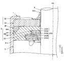
- the seal housing 81 has a contact surface that comes into contact with the outer seal 83, and the contact surface has a recess 811.
- the recess 811 is formed on the inner peripheral surface 810 of the seal housing 81. More specifically, the recess 811 is a recess formed in the third cylindrical surface 8103 of the inner peripheral surface 810.
- the recess 811 extends along the circumferential direction.
- the recess 811 is a groove having a triangular shape in cross-sectional view. The width along the axis AX in the cross-sectional view in the recess 811 increases from the cylinder 1 toward the rod 4.
- the inner seal 82 has a portion extending along the radial direction of the rod 4 and a portion extending along the axis AX. As shown in FIG. 3, the inner seal 82 has a tightening allowance with respect to the outer peripheral surface of the rod 4.
- the inner seal 82 is held in the first space C1 in a state of being pressed against the seal housing 81 and the rod 4. Further, the inner seal 82 is held in the second space C2 in a state of being pressed by the outer seal 83 and the rod 4. Further, the movement of the inner seal 82 in the Z1 direction is restricted by the seal housing 81, and the inner seal 82 is pressed in the Z1 direction by the hydraulic pressure of the hydraulic oil that has entered the gap C0. Further, the inner seal 82 is formed of an elastic material such as fluororubber or nitrile butadiene rubber (NBR).
- NBR nitrile butadiene rubber
- the outer seal 83 is arranged between the inner seal 82 and the seal housing 81 and comes into contact with them.
- the outer seal 83 is press-fitted between the inner seal 82 and the seal housing 81. Therefore, as shown in FIG. 2, in the state where the outer seal 83 is assembled, the inner peripheral edge of the outer seal 83 is slightly displaced in the Z2 direction.
- the outer seal 83 is formed of an elastic material such as nitrile, butadiene, rubber (NBR) and the like.
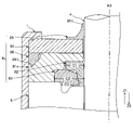
- FIG. 4 is a diagram for explaining the state of the outer seal 83 included in the sealing device 8x of the reference example.
- the seal housing 81x included in the sealing device 8x of the reference example does not have the recess 811 shown in FIGS. 2 and 3.
- the inner seal 82 is pushed in the radial direction away from the axis AX by the rod 4, so that the inner seal 82 tries to escape toward the gap C0.
- the outer seal 83 may be partially separated from the inner seal 82 as shown in FIG.
- the contact between the inner seal 82 and the rod 4 becomes unstable, and the pressing force of the inner seal 82 against the rod 4 is reduced. Therefore, the original sealing performance of the inner seal 82 cannot be obtained, and as a result, hydraulic oil may leak.
- a recess 811 is provided in the seal housing 81 as shown in FIGS. 2 and 3 in order to solve such a problem.
- the seal housing 81 has a contact surface that contacts the outer seal 83, and the contact surface has the recess 811 so that when the sealing device 8 is incorporated into the rod 4, it is pushed by the inner seal 82 as shown in FIG. A part of the outer seal 83 is deformed so as to bite into the recess 811 of the seal housing 81.
- the recess 811 functions as an escape portion through which the outer seal 83 pressed by the inner seal 82 escapes. Therefore, it is possible to prevent the outer seal 83 from being partially or wholly separated from the inner seal 82. Therefore, the deterioration of the sealing property due to the inner seal 82 is suppressed. Therefore, the original sealing property of the sealing device 8 can be maintained.
- FIG. 5 is a diagram showing a part of the sealing device 8A of the second embodiment.
- the difference between the sealing device 8A of the second embodiment and the sealing device 8 of the first embodiment will be described, and the same matters will be omitted as appropriate.
- the outer seal 83A included in the sealing device 8A shown in FIG. 5 has a contact surface in contact with the seal housing 81A, and the contact surface has a recess 831.
- the recess 831 is a recess formed on the outer peripheral surface of the outer seal 83A.
- the recess 831 extends along the circumferential direction.
- the recess 831 is a groove having a triangular shape in cross-sectional view.
- the width of the recess 831 along the axis AX in the cross-sectional view increases from the rod 4 toward the cylinder 1.
- the seal housing 81A included in the structure 80A does not have the recess 811 of the first embodiment.
- the outer seal 83A Since the outer seal 83A has a contact surface in contact with the seal housing 81A and the contact surface has a recess 831, although not shown, the outer seal pressed by the inner seal 82 when the sealing device 8A is incorporated into the rod 4.
- the 83A is deformed by being pressed against the inner peripheral surface of the seal housing 81A. Due to this deformation, the recess 831 is deformed and pressed against the inner peripheral surface of the seal housing 81A. Therefore, it is possible to prevent the outer seal 83A from being partially or wholly separated from the inner seal 82. Therefore, the deterioration of the sealing property due to the inner seal 82 is suppressed. Therefore, the original sealing property of the sealing device 8A can be maintained.
- FIG. 6 is a diagram showing a part of the sealing device 8B of the third embodiment.
- the difference between the sealing device 8B of the third embodiment and the sealing device 8 of the first embodiment will be described, and the same matters will be omitted as appropriate.
- the seal housing 81B included in the structure 80B of the sealing device 8B shown in FIG. 6 has a second portion 812 composed of recesses.
- the second portion 812 has the same configuration as the recess 811 of the first embodiment.
- the seal housing 81B has a contact surface that contacts the outer peripheral surface of the outer seal 83B, and the second portion 812 is formed on the contact surface.
- the second portion 812 is formed on the third cylindrical surface 8103.
- the second portion 812 extends along the circumferential direction.
- the second portion 812 is a groove having a triangular shape in a cross-sectional view.
- the outer seal 83B has a first portion 832 composed of a convex portion.
- the first portion 832 fits into the second portion 812.
- the outer seal 83B has a contact surface in contact with the third cylindrical surface 8103, and the first portion 832 is formed on the contact surface.
- the first portion 832 extends along the circumferential direction.
- the first portion 832 is a protrusion having a triangular shape in a cross-sectional view.
- the seal housing 81B has a second portion 812, and the outer seal 83B has a first portion 832 that fits into the second portion 812. Therefore, when the sealing device 8B is incorporated into the rod 4, the outer seal 83B is difficult to be removed from the structure 80B. Therefore, it is possible to prevent the outer seal 83B from being partially or wholly separated from the inner seal 82. Therefore, the deterioration of the sealing property due to the inner seal 82 is suppressed. Therefore, the original sealing property of the sealing device 8B can be maintained.
- FIG. 7 is a diagram showing a part of the sealing device 8C of the fourth embodiment.
- the difference between the sealing device 8C of the third embodiment and the sealing device 8 of the first embodiment will be described, and the same matters will be omitted as appropriate.
- the seal housing 81C included in the structure 80C of the sealing device 8C shown in FIG. 7 has a second portion 813 formed of a convex portion.
- the seal housing 81C has a contact surface that contacts the outer peripheral surface of the outer seal 83C, and the second portion 813 is formed on the contact surface.
- the second portion 813 is formed on the third cylindrical surface 8103.
- the second portion 813 extends along the circumferential direction.
- the second portion 813 is a protrusion having a triangular shape in a cross-sectional view.
- the outer seal 83C has a first portion 833 composed of recesses.
- the first portion 833 fits into the second portion 813.
- the outer seal 83C has a contact surface that contacts the third cylindrical surface 8103, and the first portion 833 is formed on the contact surface.
- the first portion 833 extends along the circumferential direction.
- the first portion 833 is a groove having a triangular shape in a cross-sectional view.
- the seal housing 81C has a second portion 813 and the outer seal 83C has a first portion 833 that fits into the second portion 813. Therefore, when the sealing device 8C is incorporated into the rod 4, the outer seal 83C is difficult to be removed from the structure 80C. Therefore, it is possible to prevent the outer seal 83C from being partially or wholly separated from the inner seal 82. Therefore, the deterioration of the sealing property due to the inner seal 82 is suppressed. Therefore, the original sealing property of the sealing device 8C can be maintained.
- FIG. 8 is a diagram showing a part of the sealing device 8D of the fifth embodiment.
- the difference between the sealing device 8D of the fifth embodiment and the sealing device 8 of the first embodiment will be described, and the same matters will be omitted as appropriate.
- the seal housing 81D included in the structure 80D of the sealing device 8D shown in FIG. 8 has a second portion 814 composed of a plurality of concave portions and a plurality of convex portions.
- the seal housing 81D has a contact surface that contacts the outer peripheral surface of the outer seal 83D, and the second portion 814 is formed on the contact surface.
- the second portion 814 is formed on the third cylindrical surface 8103. The second portion 814 extends along the circumferential direction.
- the inner seal 82D has a second portion 821 composed of a plurality of concave portions and a plurality of convex portions.
- the inner seal 82D has a contact surface that contacts the inner peripheral surface of the outer seal 83D, and the second portion 821 is formed on the contact surface.
- the second portion 821 is formed on the outer peripheral surface of the inner seal 82D.
- the second portion 821 extends along the circumferential direction.
- the outer seal 83D has two first portions 834 and 835.
- Each of the first portions 834 and 835 is composed of a plurality of recesses and a plurality of protrusions.
- the first portion 834 fits into the second portion 814 and the first portion 835 fits into the second portion 821.
- the outer seal 83D has a contact surface that contacts the third cylindrical surface 8103, and the first portion 834 is formed on the contact surface.
- the first portion 834 is formed on the outer peripheral surface of the outer seal 83D.
- the outer seal 83D has a contact surface in contact with the inner seal 82D, and the first portion 835 is formed on the contact surface.
- the first portion 835 is formed on the inner peripheral surface of the outer seal 83D.
- each of the first portions 834 and 835 extends along the circumferential direction.
- the seal housing 81D has a second portion 814 and the inner seal 82D has a second portion 821.
- the outer seal 83D has a first portion 834 that fits into the second portion 814 and a first portion 835 that fits into the second portion 821. Therefore, when the sealing device 8D is incorporated into the rod 4, the outer seal 83D is difficult to be removed from the structure 80D. Therefore, it is possible to prevent the outer seal 83D from being partially or wholly separated from the inner seal 82D. Therefore, the deterioration of the sealing property due to the inner seal 82D is suppressed. Therefore, the original sealing property of the sealing device 8D can be maintained.
- the outer seal 83D has two first portions 834 and 835. Therefore, it is possible to prevent the outer seal 83D from being partially or wholly separated from the inner seal 82D as compared with the case of having any one of them.
- FIG. 9 is a diagram showing a part of the sealing device 8E of the sixth embodiment.
- the difference between the sealing device 8E of the sixth embodiment and the sealing device 8 of the first embodiment will be described, and the same matters will be omitted as appropriate.
- the inner seal 82E included in the structure 80E of the sealing device 8E shown in FIG. 9 has a second portion 822 composed of a convex portion.
- the inner seal 82E has a contact surface that contacts the inner peripheral surface of the outer seal 83E, and the second portion 822 is formed on the contact surface.
- the second portion 822 is formed on the outer peripheral surface of the inner seal 82E.
- the second portion 822 extends along the circumferential direction.
- the second portion 822 is a protrusion having a quadrangular shape in a cross-sectional view.
- the seal housing 81E does not have the recess 811 of the first embodiment.
- the outer seal 83E has a first portion 836 composed of recesses.
- the first portion 836 fits into the second portion 822.
- the outer seal 83E has a contact surface in contact with the inner seal 82E, and the first portion 836 is formed on the contact surface.
- the first portion 836 is formed on the inner peripheral surface of the outer seal 83E.
- the first portion 836 extends along the circumferential direction.
- the first portion 836 is a groove having a rectangular shape in a cross-sectional view.
- the inner seal 82E has a second portion 822
- the outer seal 83E has a first portion 836 that fits into the second portion 822. Therefore, when the sealing device 8E is incorporated into the rod 4, the outer seal 83E is difficult to be removed from the inner seal 82E. Therefore, it is possible to prevent the outer seal 83E from being partially or wholly separated from the inner seal 82E. Therefore, the deterioration of the sealing property due to the inner seal 82E is suppressed. Therefore, the original sealing property of the sealing device 8E can be maintained.
- the inner seal 82E and the outer seal 83E are fitted by the first portion 836 and the second portion 822, so that the inner seal 82E and the outer seal 83E can be integrated. Therefore, it is possible to effectively prevent the outer seal 83E from being partially or wholly separated from the inner seal 82E.
- FIG. 10 is a diagram showing a part of the sealing device 8F of the seventh embodiment.
- the difference between the sealing device 8F of the sixth embodiment and the sealing device 8 of the first embodiment will be described, and the same matters will be omitted as appropriate.
- the inner seal 82F included in the structure 80F of the sealing device 8F shown in FIG. 10 has a second portion 823 composed of recesses.
- the inner seal 82F has a contact surface that contacts the inner peripheral surface of the outer seal 83F, and the second portion 823 is formed on the contact surface.
- the second portion 823 is formed on the outer peripheral surface of the inner seal 82F.
- the second portion 823 extends along the circumferential direction.
- the second portion 823 is a groove having a rectangular shape in a cross-sectional view.
- the seal housing 81F does not have the recess 811 of the first embodiment.
- the outer seal 83F has a first portion 837 composed of a convex portion.
- the first portion 837 fits into the second portion 823.
- the outer seal 83F has a contact surface that contacts the outer peripheral surface of the inner seal 82F, and the first portion 837 is formed on the contact surface.
- the first portion 837 is formed on the inner peripheral surface of the outer seal 83F.
- the first portion 837 extends along the circumferential direction.
- the first portion 837 is a protrusion having a rectangular shape in a cross-sectional view.
- the inner seal 82F has a second portion 823
- the outer seal 83F has a first portion 837 that fits into the second portion 823. Therefore, when the sealing device 8F is incorporated into the rod 4, the outer seal 83F is difficult to be removed from the inner seal 82F. Therefore, it is possible to prevent the outer seal 83F from being partially or wholly separated from the inner seal 82F. Therefore, the deterioration of the sealing property due to the inner seal 82F is suppressed. Therefore, the original sealing property of the sealing device 8F can be maintained.
- the inner seal 82F and the outer seal 83F are fitted by the first portion 837 and the second portion 823, so that the inner seal 82F and the outer seal 83F can be integrated. Therefore, it is possible to effectively prevent the outer seal 83F from being partially or wholly separated from the inner seal 82F.
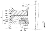
- FIG. 11 is a diagram showing a part of the sealing device 8G of the eighth embodiment.
- the difference between the sealing device 8G of the eighth embodiment and the sealing device 8 of the first embodiment will be described, and the same matters will be omitted as appropriate.
- the inner seal 82G included in the structure 80G of the sealing device 8G shown in FIG. 11 has a second portion 824.
- the second portion 824 is a convex portion.
- the inner seal 82G has a contact surface that contacts the inner peripheral surface of the outer seal 83G, and the second portion 824 is formed on the contact surface.
- the second portion 824 is formed on the outer peripheral surface of the inner seal 82G.
- the second portion 824 extends along the circumferential direction.
- the seal housing 81G does not have the recess 811 of the first embodiment.
- the outer seal 83G has a first portion 838.
- the first portion 838 is a recess.
- the first portion 838 fits into the second portion 824.
- the outer seal 83G has a contact surface that contacts the outer peripheral surface of the inner seal 82G, and the first portion 838 is formed on the contact surface.
- the first portion 838 is formed on the inner peripheral surface of the outer seal 83G.
- the first portion 838 extends along the circumferential direction.
- the second portion 824 may be regarded as a step composed of a concave portion and a convex portion
- the first portion 838 may be regarded as a step composed of the concave portion and the convex portion.
- the second portion 824 may be regarded as a concave portion
- the first portion 838 may be regarded as a convex portion.
- the inner seal 82G has a second portion 824
- the outer seal 83G has a first portion 838 that fits into the second portion 824. Therefore, when the sealing device 8G is incorporated into the rod 4, the outer seal 83G is difficult to be removed from the inner seal 82G. Therefore, it is possible to prevent the outer seal 83G from being partially or wholly separated from the inner seal 82G. Therefore, the deterioration of the sealing property due to the inner seal 82G is suppressed. Therefore, the original sealing property of the sealing device 8G can be maintained.
- the inner seal 82G and the outer seal 83G are fitted by the first portion 838 and the second portion 824, so that the inner seal 82G and the outer seal 83G can be integrated. Therefore, it is possible to effectively prevent the outer seal 83G from being partially or wholly separated from the inner seal 82G.
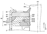
- FIG. 12 is a diagram showing a part of the sealing device 8H of the ninth embodiment.
- the difference between the sealing device 8H of the eighth embodiment and the sealing device 8 of the first embodiment will be described, and the same matters will be omitted as appropriate.
- the structure 80H of the sealing device 8H shown in FIG. 12 has a second portion 801.
- the second portion 801 is a recess included in the structure 80H.
- the second portion 801 is provided between the seal housing 81H and the inner seal 82H.
- the structure 80H has a contact surface in contact with the outer seal 83H, and the second portion 801 is formed on the contact surface.
- the second portion 801 extends along the circumferential direction.
- the outer seal 83H has a first portion 839.
- the first portion 839 is composed of a convex portion.
- the first portion 839 fits into the second portion 801.
- the outer seal 83H has a contact surface in contact with the structure 80H, and the first portion 839 is formed on the contact surface.
- the first portion 839 extends along the circumferential direction.
- the structure 80H has a second portion 801 and the outer seal 83H has a first portion 839 that fits into the second portion 801. Therefore, when the sealing device 8H is incorporated into the rod 4, the outer seal 83H is difficult to be removed from the structure 80H. Therefore, it is possible to prevent the outer seal 83H from being partially or wholly separated from the structure 80H. Therefore, it is possible to prevent the outer seal 83H from being partially or wholly separated from the inner seal 82H. Therefore, the deterioration of the sealing property due to the inner seal 82H is suppressed. Therefore, the original sealing property of the sealing device 8H can be maintained.
- the second portion 801 is provided between the seal housing 81H and the inner seal 82H, and the first portion 839 is fitted to the second portion 801. Therefore, the first portion 839 is sandwiched between the seal housing 81H and the inner seal 82H. Therefore, it is possible to effectively prevent the outer seal 83H from being partially or wholly separated from the structure 80H.
- the present invention has been described above based on each suitable embodiment, the present invention is not limited to the above-described embodiment. Further, the configuration of each part of the present invention can be replaced with an arbitrary configuration that exhibits the same function as that of the above-described embodiment, and any configuration can be added. In addition, any of the above-described configurations of each embodiment may be combined.
- the sealing device of the present invention may be applied to an expansion / contraction mechanism other than the shock absorber, for example, a gas stay.
Landscapes
- Engineering & Computer Science (AREA)
- General Engineering & Computer Science (AREA)
- Mechanical Engineering (AREA)
- Sealing Devices (AREA)
- Sealing With Elastic Sealing Lips (AREA)
Priority Applications (4)
| Application Number | Priority Date | Filing Date | Title |
|---|---|---|---|
| JP2022563633A JP7588154B2 (ja) | 2020-11-18 | 2021-10-15 | 密封装置 |
| US18/033,740 US12345310B2 (en) | 2020-11-18 | 2021-10-15 | Sealing device |
| EP21894390.0A EP4249765A4 (en) | 2020-11-18 | 2021-10-15 | SEALING DEVICE |
| CN202180072848.3A CN116420035A (zh) | 2020-11-18 | 2021-10-15 | 密封装置 |
Applications Claiming Priority (2)
| Application Number | Priority Date | Filing Date | Title |
|---|---|---|---|
| JP2020191514 | 2020-11-18 | ||
| JP2020-191514 | 2020-11-18 |
Publications (1)
| Publication Number | Publication Date |
|---|---|
| WO2022107516A1 true WO2022107516A1 (ja) | 2022-05-27 |
Family
ID=81708983
Family Applications (1)
| Application Number | Title | Priority Date | Filing Date |
|---|---|---|---|
| PCT/JP2021/038199 Ceased WO2022107516A1 (ja) | 2020-11-18 | 2021-10-15 | 密封装置 |
Country Status (5)
| Country | Link |
|---|---|
| US (1) | US12345310B2 (https=) |
| EP (1) | EP4249765A4 (https=) |
| JP (1) | JP7588154B2 (https=) |
| CN (1) | CN116420035A (https=) |
| WO (1) | WO2022107516A1 (https=) |
Citations (6)
| Publication number | Priority date | Publication date | Assignee | Title |
|---|---|---|---|---|
| JP2006226424A (ja) | 2005-02-18 | 2006-08-31 | Kayaba Ind Co Ltd | シール構造および緩衝器 |
| JP2011214639A (ja) * | 2010-03-31 | 2011-10-27 | Hitachi Automotive Systems Ltd | シリンダ装置 |
| JP2015510570A (ja) * | 2012-02-20 | 2015-04-09 | トレルボルグ シーリング ソリューションズ ジャーマニー ゲーエムベーハーTrelleborg Sealing Solutions Germany GmbH | シール装置及びシール装置の製造方法 |
| US20150316119A1 (en) * | 2012-11-27 | 2015-11-05 | Thyssenkrupp Bilstein Gmbh | Closure package for closing a damper tube for a vibration damper |
| JP2015218817A (ja) * | 2014-05-19 | 2015-12-07 | カヤバ工業株式会社 | 緩衝器 |
| JP2018048664A (ja) * | 2016-09-20 | 2018-03-29 | Kyb株式会社 | ショックアブソーバ |
Family Cites Families (15)
| Publication number | Priority date | Publication date | Assignee | Title |
|---|---|---|---|---|
| US3848880A (en) * | 1972-06-09 | 1974-11-19 | Tanner Eng Co | Fluid seal |
| DE3813037C1 (https=) * | 1988-04-19 | 1989-09-14 | Fa. Carl Freudenberg, 6940 Weinheim, De | |
| EP0563439B1 (de) * | 1992-03-31 | 1996-01-03 | Firma Carl Freudenberg | Dichtung für eine hin- und hergehende Stange |
| KR100483645B1 (ko) | 1999-02-18 | 2005-04-18 | 카야바 고교 가부시기가이샤 | 밀봉 구조 |
| JP2000346202A (ja) | 1999-06-07 | 2000-12-15 | Kayaba Ind Co Ltd | シ−ル構造 |
| US6318521B1 (en) * | 1999-06-16 | 2001-11-20 | Bridgestone/Firestone, Inc. | Externally guided ER damper |
| DE19938785A1 (de) | 1999-08-16 | 2001-03-22 | Cr Elastomere Gmbh | Dichtungsanordnung zur Abdichtung eines stangenförmigen Elements |
| JP4639619B2 (ja) | 2004-03-23 | 2011-02-23 | Nok株式会社 | 往復動軸用密封装置 |
| DE102006050439B4 (de) * | 2006-10-26 | 2019-01-10 | Ab Skf | Dichtungsanordnung und Gelenk einer Kette mit der Dichtungsanordnung |
| DE102008049911B4 (de) * | 2008-10-02 | 2023-05-04 | Ab Skf | Dichtungsanordnung und Gelenk einer Kette mit der Dichtungsanordnung |
| JP5237863B2 (ja) | 2009-03-23 | 2013-07-17 | 本田技研工業株式会社 | ダンパ装置 |
| US9933071B2 (en) * | 2015-02-25 | 2018-04-03 | Aktiebolaget Skf | Seal and method of manufacturing and/or using same |
| US11193589B2 (en) | 2017-03-29 | 2021-12-07 | Nok Corporation | Sealing device |
| US11118684B2 (en) * | 2018-02-28 | 2021-09-14 | Kaydon Ring & Seal, Inc. | Retainer device for circumferential shaft seals |
| US11536346B2 (en) | 2018-03-15 | 2022-12-27 | Kyb Corporation | Shock absorber |
-
2021
- 2021-10-15 WO PCT/JP2021/038199 patent/WO2022107516A1/ja not_active Ceased
- 2021-10-15 CN CN202180072848.3A patent/CN116420035A/zh active Pending
- 2021-10-15 US US18/033,740 patent/US12345310B2/en active Active
- 2021-10-15 JP JP2022563633A patent/JP7588154B2/ja active Active
- 2021-10-15 EP EP21894390.0A patent/EP4249765A4/en active Pending
Patent Citations (6)
| Publication number | Priority date | Publication date | Assignee | Title |
|---|---|---|---|---|
| JP2006226424A (ja) | 2005-02-18 | 2006-08-31 | Kayaba Ind Co Ltd | シール構造および緩衝器 |
| JP2011214639A (ja) * | 2010-03-31 | 2011-10-27 | Hitachi Automotive Systems Ltd | シリンダ装置 |
| JP2015510570A (ja) * | 2012-02-20 | 2015-04-09 | トレルボルグ シーリング ソリューションズ ジャーマニー ゲーエムベーハーTrelleborg Sealing Solutions Germany GmbH | シール装置及びシール装置の製造方法 |
| US20150316119A1 (en) * | 2012-11-27 | 2015-11-05 | Thyssenkrupp Bilstein Gmbh | Closure package for closing a damper tube for a vibration damper |
| JP2015218817A (ja) * | 2014-05-19 | 2015-12-07 | カヤバ工業株式会社 | 緩衝器 |
| JP2018048664A (ja) * | 2016-09-20 | 2018-03-29 | Kyb株式会社 | ショックアブソーバ |
Non-Patent Citations (1)
| Title |
|---|
| See also references of EP4249765A4 |
Also Published As
| Publication number | Publication date |
|---|---|
| US12345310B2 (en) | 2025-07-01 |
| US20230392665A1 (en) | 2023-12-07 |
| CN116420035A (zh) | 2023-07-11 |
| JPWO2022107516A1 (https=) | 2022-05-27 |
| JP7588154B2 (ja) | 2024-11-21 |
| EP4249765A4 (en) | 2024-10-09 |
| EP4249765A1 (en) | 2023-09-27 |
Similar Documents
| Publication | Publication Date | Title |
|---|---|---|
| CN111936764A (zh) | 阀以及缓冲器 | |
| JP6335019B2 (ja) | 緩衝器 | |
| JP6374701B2 (ja) | 緩衝器 | |
| CN106460995A (zh) | 缓冲器 | |
| WO2020095806A1 (ja) | 緩衝器 | |
| JP7002376B2 (ja) | ショックアブソーバ | |
| WO2019176784A1 (ja) | ショックアブソーバ | |
| KR100477772B1 (ko) | 유압완충기 | |
| JP6845643B2 (ja) | ショックアブソーバ | |
| CN107923469B (zh) | 缓冲器的阀构造 | |
| JP4442842B2 (ja) | ダンパのリバウンドストッパ構造 | |
| WO2022107516A1 (ja) | 密封装置 | |
| JP7450583B2 (ja) | 緩衝器 | |
| US11608138B2 (en) | Sealing device in particular for shock-absorber stems | |
| JP6956595B2 (ja) | 緩衝器 | |
| JP7653894B2 (ja) | 緩衝器 | |
| WO2018056099A1 (ja) | 緩衝器 | |
| WO2018216762A1 (ja) | 緩衝器 | |
| WO2017051715A1 (ja) | ショックアブソーバ | |
| JP6978965B2 (ja) | ショックアブソーバ | |
| JP6246425B1 (ja) | 緩衝器 | |
| WO2018092327A1 (ja) | 緩衝器 | |
| WO2024201696A1 (ja) | 緩衝装置、懸架装置 | |
| JP2010096205A (ja) | 軸シール構造 | |
| JP4322737B2 (ja) | シリンダヘッドカバーのシール機構 |
Legal Events
| Date | Code | Title | Description |
|---|---|---|---|
| 121 | Ep: the epo has been informed by wipo that ep was designated in this application |
Ref document number: 21894390 Country of ref document: EP Kind code of ref document: A1 |
|
| ENP | Entry into the national phase |
Ref document number: 2022563633 Country of ref document: JP Kind code of ref document: A |
|
| NENP | Non-entry into the national phase |
Ref country code: DE |
|
| ENP | Entry into the national phase |
Ref document number: 2021894390 Country of ref document: EP Effective date: 20230619 |
|
| WWG | Wipo information: grant in national office |
Ref document number: 18033740 Country of ref document: US |