WO2022107457A1 - 管更生工法 - Google Patents
管更生工法 Download PDFInfo
- Publication number
- WO2022107457A1 WO2022107457A1 PCT/JP2021/036030 JP2021036030W WO2022107457A1 WO 2022107457 A1 WO2022107457 A1 WO 2022107457A1 JP 2021036030 W JP2021036030 W JP 2021036030W WO 2022107457 A1 WO2022107457 A1 WO 2022107457A1
- Authority
- WO
- WIPO (PCT)
- Prior art keywords
- nut
- pipe
- holding member
- segment
- groove
- Prior art date
- Legal status (The legal status is an assumption and is not a legal conclusion. Google has not performed a legal analysis and makes no representation as to the accuracy of the status listed.)
- Ceased
Links
Images










Classifications
-
- F—MECHANICAL ENGINEERING; LIGHTING; HEATING; WEAPONS; BLASTING
- F16—ENGINEERING ELEMENTS AND UNITS; GENERAL MEASURES FOR PRODUCING AND MAINTAINING EFFECTIVE FUNCTIONING OF MACHINES OR INSTALLATIONS; THERMAL INSULATION IN GENERAL
- F16L—PIPES; JOINTS OR FITTINGS FOR PIPES; SUPPORTS FOR PIPES, CABLES OR PROTECTIVE TUBING; MEANS FOR THERMAL INSULATION IN GENERAL
- F16L55/00—Devices or appurtenances for use in, or in connection with, pipes or pipe systems
- F16L55/16—Devices for covering leaks in pipes or hoses, e.g. hose-menders
- F16L55/162—Devices for covering leaks in pipes or hoses, e.g. hose-menders from inside the pipe
- F16L55/165—Devices for covering leaks in pipes or hoses, e.g. hose-menders from inside the pipe a pipe or flexible liner being inserted in the damaged section
-
- F—MECHANICAL ENGINEERING; LIGHTING; HEATING; WEAPONS; BLASTING
- F16—ENGINEERING ELEMENTS AND UNITS; GENERAL MEASURES FOR PRODUCING AND MAINTAINING EFFECTIVE FUNCTIONING OF MACHINES OR INSTALLATIONS; THERMAL INSULATION IN GENERAL
- F16L—PIPES; JOINTS OR FITTINGS FOR PIPES; SUPPORTS FOR PIPES, CABLES OR PROTECTIVE TUBING; MEANS FOR THERMAL INSULATION IN GENERAL
- F16L55/00—Devices or appurtenances for use in, or in connection with, pipes or pipe systems
- F16L55/16—Devices for covering leaks in pipes or hoses, e.g. hose-menders
- F16L55/162—Devices for covering leaks in pipes or hoses, e.g. hose-menders from inside the pipe
- F16L55/165—Devices for covering leaks in pipes or hoses, e.g. hose-menders from inside the pipe a pipe or flexible liner being inserted in the damaged section
- F16L55/1657—Devices for covering leaks in pipes or hoses, e.g. hose-menders from inside the pipe a pipe or flexible liner being inserted in the damaged section lengths of rigid pipe being inserted
-
- E—FIXED CONSTRUCTIONS
- E21—EARTH OR ROCK DRILLING; MINING
- E21D—SHAFTS; TUNNELS; GALLERIES; LARGE UNDERGROUND CHAMBERS
- E21D11/00—Lining tunnels, galleries or other underground cavities, e.g. large underground chambers; Linings therefor; Making such linings in situ, e.g. by assembling
- E21D11/14—Lining predominantly with metal
- E21D11/18—Arch members ; Network made of arch members ; Ring elements; Polygon elements; Polygon elements inside arches
- E21D11/20—Special cross- sections, e.g. corrugated
-
- F—MECHANICAL ENGINEERING; LIGHTING; HEATING; WEAPONS; BLASTING
- F16—ENGINEERING ELEMENTS AND UNITS; GENERAL MEASURES FOR PRODUCING AND MAINTAINING EFFECTIVE FUNCTIONING OF MACHINES OR INSTALLATIONS; THERMAL INSULATION IN GENERAL
- F16B—DEVICES FOR FASTENING OR SECURING CONSTRUCTIONAL ELEMENTS OR MACHINE PARTS TOGETHER, e.g. NAILS, BOLTS, CIRCLIPS, CLAMPS, CLIPS OR WEDGES; JOINTS OR JOINTING
- F16B37/00—Nuts or like thread-engaging members
- F16B37/14—Cap nuts; Nut caps or bolt caps
-
- F—MECHANICAL ENGINEERING; LIGHTING; HEATING; WEAPONS; BLASTING
- F16—ENGINEERING ELEMENTS AND UNITS; GENERAL MEASURES FOR PRODUCING AND MAINTAINING EFFECTIVE FUNCTIONING OF MACHINES OR INSTALLATIONS; THERMAL INSULATION IN GENERAL
- F16L—PIPES; JOINTS OR FITTINGS FOR PIPES; SUPPORTS FOR PIPES, CABLES OR PROTECTIVE TUBING; MEANS FOR THERMAL INSULATION IN GENERAL
- F16L55/00—Devices or appurtenances for use in, or in connection with, pipes or pipe systems
- F16L55/16—Devices for covering leaks in pipes or hoses, e.g. hose-menders
- F16L55/162—Devices for covering leaks in pipes or hoses, e.g. hose-menders from inside the pipe
-
- F—MECHANICAL ENGINEERING; LIGHTING; HEATING; WEAPONS; BLASTING
- F16—ENGINEERING ELEMENTS AND UNITS; GENERAL MEASURES FOR PRODUCING AND MAINTAINING EFFECTIVE FUNCTIONING OF MACHINES OR INSTALLATIONS; THERMAL INSULATION IN GENERAL
- F16L—PIPES; JOINTS OR FITTINGS FOR PIPES; SUPPORTS FOR PIPES, CABLES OR PROTECTIVE TUBING; MEANS FOR THERMAL INSULATION IN GENERAL
- F16L55/00—Devices or appurtenances for use in, or in connection with, pipes or pipe systems
- F16L55/16—Devices for covering leaks in pipes or hoses, e.g. hose-menders
- F16L55/162—Devices for covering leaks in pipes or hoses, e.g. hose-menders from inside the pipe
- F16L55/1645—Devices for covering leaks in pipes or hoses, e.g. hose-menders from inside the pipe a sealing material being introduced inside the pipe by means of a tool moving in the pipe
-
- F—MECHANICAL ENGINEERING; LIGHTING; HEATING; WEAPONS; BLASTING
- F16—ENGINEERING ELEMENTS AND UNITS; GENERAL MEASURES FOR PRODUCING AND MAINTAINING EFFECTIVE FUNCTIONING OF MACHINES OR INSTALLATIONS; THERMAL INSULATION IN GENERAL
- F16L—PIPES; JOINTS OR FITTINGS FOR PIPES; SUPPORTS FOR PIPES, CABLES OR PROTECTIVE TUBING; MEANS FOR THERMAL INSULATION IN GENERAL
- F16L9/00—Rigid pipes
- F16L9/22—Pipes composed of a plurality of segments
-
- F—MECHANICAL ENGINEERING; LIGHTING; HEATING; WEAPONS; BLASTING
- F16—ENGINEERING ELEMENTS AND UNITS; GENERAL MEASURES FOR PRODUCING AND MAINTAINING EFFECTIVE FUNCTIONING OF MACHINES OR INSTALLATIONS; THERMAL INSULATION IN GENERAL
- F16L—PIPES; JOINTS OR FITTINGS FOR PIPES; SUPPORTS FOR PIPES, CABLES OR PROTECTIVE TUBING; MEANS FOR THERMAL INSULATION IN GENERAL
- F16L55/00—Devices or appurtenances for use in, or in connection with, pipes or pipe systems
- F16L55/16—Devices for covering leaks in pipes or hoses, e.g. hose-menders
- F16L55/162—Devices for covering leaks in pipes or hoses, e.g. hose-menders from inside the pipe
- F16L55/163—Devices for covering leaks in pipes or hoses, e.g. hose-menders from inside the pipe a ring, a band or a sleeve being pressed against the inner surface of the pipe
Definitions
- a segment formed by integrally forming an inner surface plate constituting an inner peripheral surface and a side plate and an end plate erected on the peripheral edge of the inner surface plate with plastic is connected in the circumferential direction and the pipe length direction.
- a segment When rehabilitating a large-diameter pipeline, a segment is used in which the inner surface plate constituting the inner peripheral surface and the side plates and end plates erected on the peripheral edge of the inner surface plate are integrally formed of plastic.
- the segments are connected in the circumferential direction to assemble a pipe unit, and the pipe unit is connected in the pipe length direction via a connecting bolt to assemble a rehabilitated pipe in an existing pipe.
- Patent Document 1 a long connecting bolt extending between both side plates of the segment in the pipe length direction is used, and the connecting bolt is fixed to the segment, and the connecting bolts are connected to each other to connect the segments in the pipe length direction. Is described.
- Patent Document 2 describes a configuration in which a nut is fixed to one segment and a connecting bolt is screwed into a nut fixed to the one segment through the other segment to connect both segments in the pipe length direction. Has been done.
- the connecting bolts are connected to each other in the pipe length direction to form a long rod-shaped member connected to each other, and each segment is connected in the pipe length direction.
- the segment portion where the connecting bolt is present is firmly connected, but the segment cannot be bonded in the pipe length direction with sufficient strength in the portion where the connecting bolt is not present.
- the nuts are fixed by shifting them in the circumferential direction so that the connecting bolts are arranged in a zigzag shape. Therefore, the segments are connected in the pipe length direction with sufficient strength. Will be possible.
- the nut is a long nut that is attached over the side plate of the segment and the internal plate adjacent to it, it is necessary to form the threaded part that is screwed with the threaded part of the connecting bolt over the entire internal length of the long nut. There was a problem that expensive nuts were required.
- the present invention has been made to solve such a problem, and an object of the present invention is to provide a pipe rehabilitation method capable of connecting segments in the pipe length direction at low cost.
- the present invention A segment having an inner surface plate, side plates erected on both sides of the inner surface plate, and a plurality of internal plates erected on the upper surface of the inner surface plate inside the side plate is connected in the circumferential direction and the pipe length direction into the existing pipe. It is a pipe rehabilitation method for laying rehabilitation pipes.
- the length of the nut in the pipe length direction is set to the side plate and the side plate thereof. It can be smaller than the distance between the inner plates adjacent to it, and a small and inexpensive nut can be used. Further, since the nut is press-fitted into the groove formed in the nut holding member, the nut can be securely and easily attached, and the nut holding member can be easily attached and detached. Therefore, if the nut attachment position is incorrect. However, the effect is that you can easily start over.
- the present invention is suitable for rehabilitating or repairing existing large diameter pipes such as sewer pipes, water pipes, tunnels, or agricultural canals.
- the rehabilitation tube is described as having a circular cross-sectional shape orthogonal to the pipe length direction, but it is needless to say that the present invention can be applied to a rehabilitation tube having a shape other than a circle such as a rectangle. Further, the present invention can be applied even when the cross-sectional shape is not a closed shape as a pipe but a shape with one side open such as a horseshoe shape, a semicircular shape, or a concave shape.
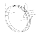
- the pipe length direction is the direction indicated by the arrow X extending in the pipe length direction of the pipe unit 10 in FIG. 2, and the circumferential direction is the circumferential direction of the circle of the pipe unit 10.
- FIG. 1 illustrates the structure of the rehabilitation tube segment 1 (hereinafter, simply referred to as a segment).
- the segment 1 includes an inner surface plate 101 constituting the inner peripheral surface of the rehabilitation pipe, side plates 102 and 103 having the same plate thickness vertically erected on both sides extending in the circumferential direction of the inner surface plate 101, and the pipe length of the inner surface plate 101. It is an integrally molded block-shaped member made of plastic composed of end plates 104 and 105 erected vertically at both ends extending in the direction.
- a plurality of inner plates 106, 107 having the same thickness as the side plates 102, 103 and having the same shape are arranged inside the side plates 102, 103. It is erected at equal intervals in parallel with 102 and 103.
- the segment 1 has a shape curved in an arc shape of 60 degrees which divides the circumference into a plurality of equal parts, for example, 6 equal parts, but the cross-sectional shape of the existing pipe, its size, or the repair of the existing pipe. Depending on the location, it can be a rectangular parallelepiped or a bent shape with a rounded shape at a right angle.
- a plurality of circular insertion holes 102a and 103a for passing the connecting bolt 11 are formed in the side plates 102 and 103 at equal intervals in the circumferential direction.
- a plurality of circular insertion holes 106a having a diameter smaller than the insertion holes 102a and 103a for passing the connecting bolts 11 are also formed in the inner plate 106 at equal intervals, and the connecting bolts can be inserted into the inner plate 107 and function as insertion holes.
- a plurality of notches 107a are formed at equal intervals.
- the insertion holes 102a, 103a, 106a, and the notch 107a have the same positions in the circumferential direction.
- the end plates 104 and 105 are members arranged between the side plates 102 and the side plates 103, and the end plates 104 and 105 have circular insertion holes for passing connecting bolts such as bolts that connect the segments 1 in the circumferential direction.
- a plurality of 104a and 105a are formed.
- segment 1 the end plate 105 and the end plate 104 of another segment are aligned and brought into contact with each other, the bolt 6 and the nut 7 (FIG. 3) are positioned in the insertion holes 104a and 105a, and the bolt 6 and the nut 7 are placed. By screwing, they can be connected in the circumferential direction.
- FIG. 2 By sequentially connecting the segments for one round in the circumferential direction, it is possible to assemble a ring-shaped pipe unit 10 having a predetermined width D perpendicular to the pipe length direction X as shown in FIG.
- the outer diameter of the pipe unit 10 is slightly smaller than the inner diameter of the existing pipe to be rehabilitated.
- the inner surface plate 101, the side plates 102, 103, the end plates 104, 105, which are the main structural members of the segment 1, are shown, and the reinforcing structure of the inner plates 106, 107 and the like avoids complexity. Therefore, the illustration is omitted.
- such pipe units 10 are sequentially connected in the pipe length direction.
- a plastic nut holding member for holding a nut 60 as shown in FIGS. 5a and 5b between the side plates 102 of the pipe unit segments 1a, 1b, and 1c and the inner plate 106 adjacent to the side plates 102.
- a plurality of 50s are attached.
- the connecting bolt 11 is connected to the side plates 102, 103 formed in the segment, the insertion holes 102a, 103a, 106a formed in the inner plate 106, and the notch 107a formed in the inner plate 107. It is connected in the pipe length direction by being inserted and screwed with the nut 60 held in the nut holding member 50.
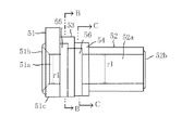
- the nut holding member 50 has a length t1 in the pipe length direction according to the distance t1'(FIG. 9) between the side plate 102 of the segment and the inner plate 106 adjacent thereto.
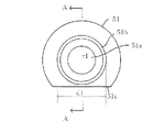
- a hollow columnar portion 51 is provided at one end thereof, a hollow cylindrical portion 52 is provided at the other end portion, and the columnar portions 53 and 54 having grooves 55 and 56 into which the nut 60 is press-fitted are provided.
- the cylindrical portions 51 and 52 coaxially have hollow portions 51a and 52a having a diameter r1 through which the connecting bolt 11 can be passed.
- the hollow portions 51a and 52a communicate with each other through the grooves 55 and 56 of the cylindrical portions 53 and 54, and a continuous hollow portion is formed in the nut holding member 50.
- the length t2 in the pipe length direction of the columnar portion 51 is set to be substantially the same as the plate thickness of the side plates 102, 103, and the inner plates 106, 107 of the segment, and the length in the pipe length direction of the columnar portions 53, 54 is the pipe length of the columnar portion 51. It is almost the same as the direction length t2.
- the cylindrical portions 51 and 53 have a larger diameter than the other cylindrical portions 52 and 54, and when the nut holding member 50 is attached between the side plate 102 and the inner plate 106, the bottom of the cylindrical portions 51 and 53 is the inner surface plate 101. Since it collides with the upper part of the cylinder, the bottom portion is cut into a horizontal flat surface 51c (see also FIG. 10).
- a ring-shaped protrusion 51b is formed on the outer surface of the columnar portion 51 (the surface facing the side plate 102), and the outer diameter d1 thereof can be fitted into the insertion holes 102a and 103a in which the protrusion 51b is formed in the side plates 102 and 103. It is sized. Further, a ring-shaped protrusion 52b is formed on the outer surface of the columnar portion 52 (the surface facing the inner plate 106), and the outer diameter d2 thereof can be fitted into the insertion hole 106a in which the protrusion 52b is formed in the inner plate 106. It is sized.
- the length t3 of the nut holding member 50 including the protrusions 51b and 52b in the pipe length direction is such that the nut holding member 50 can be press-fitted between the side plate 102 of the segment and the inner plate 106 adjacent thereto.
- the protrusions 51b and 52b are fitted into the insertion holes 102a of the side plate 102 and the insertion holes 106a of the inner plate 106, and the nut holding member 50 is formed. It is prevented from falling out of the segment.
- the protrusions 51b and 52b may be formed in only one of them.
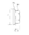
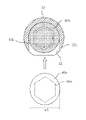
- the nut 60 press-fitted into the nut holding member 50 is a hexagon nut having a distance w2 between a circular flange portion 60a having a diameter w1 and two facing surfaces fixed thereto. It is configured as a flange nut composed of portions 60b.
- the diameter w1 of the flange portion 60a is larger than the diameter of the insertion holes 102a and 103a of the side plates 102 and 103, and the value is such that the nut 60 does not come out of the insertion holes 102a and 103a.
- the flange portion 60a and the hexagon nut portion 60b have lengths of s1 and s2 in the height direction of the nut, respectively, and the inside of the hexagon nut portion 60b is a screw portion to be screwed with the screw portion 11a of the connecting bolt 11. 60c is formed.
- the flange portion 60a of the nut 60 is press-fitted into the columnar portion 53 of the nut holding member 50, and a groove 55 extending in a direction orthogonal to the hollow portions 51a and 52a is formed.
- the groove 55 has a length s1'corresponding to the length s1 of the flange portion 60a in the pipe length direction (direction in which the nut holding member 50 extends), and as shown in FIG. 7a.
- the upper portion has an arc surface 55a corresponding to the circular shape of the flange portion 60a. Both sides of the groove 55 are vertical wall surfaces 55b and 55c, and the flange portion 60a can be inserted from the open lower portion. Since the groove 55 is formed following the columnar portion 51 in the pipe length direction, it is formed at a position separated from the outer surface of the columnar portion 51 by a distance of a thickness t2 of the side plate 102.
- a hexagon nut portion 60b is press-fitted into the columnar portions 53 and 54 of the nut holding member 50, and a groove 56 extending in a direction orthogonal to the hollow portions 51a and 52a is continuously formed in the groove 55.
- the groove 56 has a pipe length direction length s2'corresponding to the length s2 of the hexagon nut portion 60b, and a wall surface 56b separated by a distance w2' corresponding to the width w2 of the two facing surfaces of the hexagon nut portion 60b. , 56c (FIGS. 8a, 8b) are formed. Further, an arc surface 56a is formed on the upper portion of the groove 56.
- the hexagon nut portion 60b is inserted from the open lower portion of the groove 56 so that its two opposing surfaces are located between the two wall surfaces 56b and 56c. Further, on the wall surfaces 56b and 56c, protrusions 56d and 56e having a small triangular cross section extending in the pipe length direction are integrally formed with the wall surfaces 56b and 56c.
- the flange portion 60a and the hexagon nut portion 60b of the nut 60 are inserted from the open lower portions of the grooves 55 and 56, and the flange portion 60a hits the arc surface 55a of the groove 55. It is inserted until it touches. At this time, the nut 60 and the hollow portions 51a and 52a of the nut holding member 50 are coaxial, and the connecting bolt 11 can be screwed into the nut 60. Since protrusions 56d and 56e are formed on the wall surfaces 56b and 56c of the groove 56 into which the hexagon nut portion 60b is inserted, pressure input is required for inserting the hexagon nut portion 60b and press-fitting the protrusions 56d and 56e. This can prevent the protrusions 56d and 56e from being crushed and the hexagon nut portion 60b from falling out of the groove 56 due to the friction and pressure.
- the nut holding member 50 is integrally molded by injection molding using hard vinyl chloride (PVC) made of the same material as segment 1, but the material is not only hard vinyl chloride but also ABS resin and polypropylene (PP). ), Nylon, or the like, which may be a resin material that can withstand the strong alkaline component of the filler.
- PVC hard vinyl chloride
- PP polypropylene
- Nylon or the like, which may be a resin material that can withstand the strong alkaline component of the filler.
- the nut 60 When connecting the segments in the pipe length direction by using the nut holding member 50 as described above, the nut 60 is press-fitted in advance until the flange portion 60a abuts on the arc surface 55a of the groove 55 of the nut holding member 50, and the nut 60 is pressed. Is attached to the nut holding member 50. When the nut 60 is press-fitted, the hexagon nut portion 60b crushes the protrusions 56d and 56e formed in the groove 56, so that the nut 60 can be prevented from coming off from the grooves 55 and 56 due to the friction and pressure.
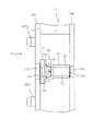
- the nut holding member 50 into which the nut 60 is press-fitted is aligned with the insertion hole 102a of the side plate 102 of the segment 1b and the insertion hole 106a of the inner plate 106 in the hollow portion 51a and the hollow portion 52a. As such, it is press-fitted between the side plate 102 and the inner plate 106 and attached. At this time, as shown in FIG.
- the protrusion 51b of the columnar portion 51 fits into the insertion hole 102a of the side plate 102 and enters the insertion hole 102a, and although not shown, the protrusion 52b of the columnar portion 52 Also, since it fits into the insertion hole 106a of the inner plate 106, the nut holding member 50 is prevented from coming off from the segment 1b.
- the nut holding member 50 is attached to a plurality of positions along the circumferential direction of the segment before transporting the segment to the construction site, for example, in a factory. In this way, the segment to which the nut holding member 50 is attached is carried into the manhole 20 as shown in FIG. 12, and is connected in the circumferential direction as shown in FIG. 2 to assemble the pipe unit 10. ..
- each segment of the pipe unit 10 is connected to the segment of another pipe unit in the pipe length direction.
- 9 and 11 show the connection of the two segments 1a and 1b in the pipe length direction.
- the side plate 102 on one side of the segment 1b to which the nut holding member 50 is attached is aligned with the side plate 103 on the other side of the segment 1a connected to the segment 1b in the pipe length direction. Since the side plate 102 is formed with protrusions 102b for alignment, when these protrusions 102b are fitted into the holes 103b of the corresponding side plates 103, the inner peripheral surfaces of the inner surface plates 101 of the segments 1a and 1b coincide with each other. Further, the insertion holes 102a and 103a of the side plates 102 and 103 are aligned so that the connecting bolt 11 can pass through.
- the protrusions 102b and the holes 103b for alignment are not shown in FIGS. 1 and 3 in order to avoid complication in the drawings.
- the connecting bolt 11 is inserted from the insertion hole 102a of the side plate 102 formed in the segment 1a into the insertion hole 106a formed in the inner plate 106 and the notch (insertion hole) 107a formed in the inner plate 107. It is screwed into the nut 60 in the nut holding member 50 through the insertion hole 103a of the side plate 103 of the segment 1a and the insertion hole 102a of the side plate 102 of the segment 1b.
- the connecting bolt 11 is configured as a long bolt, and the connecting bolt 11 is nut 60 until the head portion 11b of the connecting bolt 11a abuts on the leftmost inner plate 106 adjacent to the side plate 102 of the segment 1a.
- a sufficient tightening force is generated on the abutted side plates 102 and 103, and both segments 1a and 1b can be firmly connected in the pipe length direction.
- the groove 55 into which the flange portion 70a of the nut 60 is inserted is separated from the side plate 102 of the segment 1b toward the inner plate 106 adjacent to the side plate 102 by a predetermined distance, for example, a distance of the thickness t2 of the side plate 102. Since it is formed at the position, the segment can withstand the tightening force even if a strong tightening force is generated when the segments are connected. Further, on both sides of the groove 56 into which the hexagon nut portion 60b of the nut 60 is inserted, wall surfaces 56b and 56c separated by a distance according to the widths of two facing surfaces of the hexagon nut portion 60b are formed, and the hexagon nut is formed. Since the two surfaces of the portion 60b are inserted along the wall surfaces 56b and 56c, it is possible to prevent the nut 60 from rotating even if the connecting bolt 11 rotates.
- FIG. 3 shows a state in which the segments 1c and 1b are already connected in the pipe length direction by the connecting bolt 11, and the segment 1a is connected to the segment 1b.
- the lower connecting bolt 11 of the segment 1a has already been screwed into the nut 60 of the segment 1b, and the upper connecting bolt 11 is now screwed into the nut 60 of the segment 1b, corresponding to the state shown in FIG. ..
- the pipe unit can be connected to an arbitrary length in the pipe length direction, and the inside of the existing pipe 21 can be connected.
- the rehabilitation pipe 40 can be laid in.
- a filler is filled between the outer circumference of the rehabilitation pipe 42 and the inner wall surface of the existing pipe 21, and the rehabilitation pipe and the existing pipe are integrated.
- the nut holding member 50 since the nut holding member 50 is attached so as to be offset from the adjacent segment in the circumferential direction, the arrangement of the connecting bolts 11 becomes zigzag, and the segments can be connected in the pipe length direction with sufficient strength. Become. Further, since the nut 60 is press-fitted into the groove formed in the nut holding member 50, the nut can be securely and easily attached. Further, even if the mounting position of the nut holding member 50 is incorrect, the nut holding member 50 can be easily removed by inserting a tool below the nut holding member 50 and lifting the nut holding member 50. Can be installed in the correct position.
- the nut holding member 50 has a shape in which cylindrical members having different diameters are continuous, but the cross section may be rectangular and a rectangular parallelepiped shape.
- the type of nut is a nut with a flange, but a nut without a flange may be used.
- the nut holding member 50 was attached so that the open ends of the grooves 55 and 56 into which the nut 60 was inserted face the upper surface of the inner surface plate 101 of the segment, but the nut holding member 50 was rotated 90 degrees in the left-right direction, that is, the inner surface plate 101. It may be mounted so as to face the direction along the upper surface.
Landscapes
- Engineering & Computer Science (AREA)
- General Engineering & Computer Science (AREA)
- Mechanical Engineering (AREA)
- Mining & Mineral Resources (AREA)
- Architecture (AREA)
- Structural Engineering (AREA)
- Civil Engineering (AREA)
- Life Sciences & Earth Sciences (AREA)
- General Life Sciences & Earth Sciences (AREA)
- Geochemistry & Mineralogy (AREA)
- Geology (AREA)
- Lining And Supports For Tunnels (AREA)
- Lining Or Joining Of Plastics Or The Like (AREA)
- Orthopedics, Nursing, And Contraception (AREA)
Priority Applications (2)
| Application Number | Priority Date | Filing Date | Title |
|---|---|---|---|
| US18/037,231 US20240240740A1 (en) | 2020-11-18 | 2021-09-30 | Pipe rehabilitation method |
| JP2022563608A JP7598663B2 (ja) | 2020-11-18 | 2021-09-30 | 管更生工法 |
Applications Claiming Priority (2)
| Application Number | Priority Date | Filing Date | Title |
|---|---|---|---|
| JP2020-191966 | 2020-11-18 | ||
| JP2020191966 | 2020-11-18 |
Publications (1)
| Publication Number | Publication Date |
|---|---|
| WO2022107457A1 true WO2022107457A1 (ja) | 2022-05-27 |
Family
ID=81708883
Family Applications (1)
| Application Number | Title | Priority Date | Filing Date |
|---|---|---|---|
| PCT/JP2021/036030 Ceased WO2022107457A1 (ja) | 2020-11-18 | 2021-09-30 | 管更生工法 |
Country Status (3)
| Country | Link |
|---|---|
| US (1) | US20240240740A1 (https=) |
| JP (1) | JP7598663B2 (https=) |
| WO (1) | WO2022107457A1 (https=) |
Citations (6)
| Publication number | Priority date | Publication date | Assignee | Title |
|---|---|---|---|---|
| JPH0362213U (https=) * | 1989-10-23 | 1991-06-18 | ||
| JPH1068293A (ja) * | 1996-08-28 | 1998-03-10 | Hitachi Zosen Corp | セグメントの締結装置 |
| KR20060023504A (ko) * | 2004-09-09 | 2006-03-14 | 대한주택공사 | 천장 마감패널 설치용 너트홀더 및 체결너트 |
| JP2009243531A (ja) * | 2008-03-28 | 2009-10-22 | Ishikawajima Constr Materials Co Ltd | ナットホルダー、継手部構造及びコンクリート構造物 |
| JP2011012803A (ja) * | 2009-06-03 | 2011-01-20 | Shonan Plastic Mfg Co Ltd | 既設管の更生工法 |
| WO2016088168A1 (ja) * | 2014-12-01 | 2016-06-09 | 株式会社湘南合成樹脂製作所 | 既設管の更生工法 |
Family Cites Families (12)
| Publication number | Priority date | Publication date | Assignee | Title |
|---|---|---|---|---|
| JP2005264635A (ja) * | 2004-03-22 | 2005-09-29 | Shonan Plastic Mfg Co Ltd | 更生管用セグメント部材 |
| JP2005299711A (ja) * | 2004-04-07 | 2005-10-27 | Shonan Plastic Mfg Co Ltd | 更生管及びその敷設方法 |
| JP2005307531A (ja) * | 2004-04-21 | 2005-11-04 | Shonan Plastic Mfg Co Ltd | 更生管及びその敷設方法 |
| JP5463077B2 (ja) * | 2008-07-17 | 2014-04-09 | 株式会社湘南合成樹脂製作所 | 更生管用セグメント |
| JP5235123B2 (ja) * | 2008-10-23 | 2013-07-10 | 株式会社湘南合成樹脂製作所 | セグメントの連結方法及び連結具 |
| JP6116848B2 (ja) * | 2012-10-04 | 2017-04-19 | 株式会社湘南合成樹脂製作所 | 更生管用セグメントおよび管更生工法 |
| JP6067312B2 (ja) * | 2012-10-10 | 2017-01-25 | 株式会社湘南合成樹脂製作所 | 更生管および管更生工法 |
| JP6144072B2 (ja) * | 2013-03-01 | 2017-06-07 | 株式会社湘南合成樹脂製作所 | 管更生工法 |
| JP6529298B2 (ja) * | 2015-03-20 | 2019-06-12 | 株式会社湘南合成樹脂製作所 | 更生管の位置調整用スペーサ及びこれを用いた位置調整方法 |
| JP6555957B2 (ja) * | 2015-07-17 | 2019-08-07 | 株式会社湘南合成樹脂製作所 | 管更生工法 |
| JP6755545B2 (ja) * | 2016-06-22 | 2020-09-16 | 株式会社湘南合成樹脂製作所 | 管更生工法 |
| KR101876773B1 (ko) * | 2017-07-31 | 2018-07-11 | 주식회사 씨스 이엔지 | 관 갱생 공법 |
-
2021
- 2021-09-30 JP JP2022563608A patent/JP7598663B2/ja active Active
- 2021-09-30 US US18/037,231 patent/US20240240740A1/en active Pending
- 2021-09-30 WO PCT/JP2021/036030 patent/WO2022107457A1/ja not_active Ceased
Patent Citations (6)
| Publication number | Priority date | Publication date | Assignee | Title |
|---|---|---|---|---|
| JPH0362213U (https=) * | 1989-10-23 | 1991-06-18 | ||
| JPH1068293A (ja) * | 1996-08-28 | 1998-03-10 | Hitachi Zosen Corp | セグメントの締結装置 |
| KR20060023504A (ko) * | 2004-09-09 | 2006-03-14 | 대한주택공사 | 천장 마감패널 설치용 너트홀더 및 체결너트 |
| JP2009243531A (ja) * | 2008-03-28 | 2009-10-22 | Ishikawajima Constr Materials Co Ltd | ナットホルダー、継手部構造及びコンクリート構造物 |
| JP2011012803A (ja) * | 2009-06-03 | 2011-01-20 | Shonan Plastic Mfg Co Ltd | 既設管の更生工法 |
| WO2016088168A1 (ja) * | 2014-12-01 | 2016-06-09 | 株式会社湘南合成樹脂製作所 | 既設管の更生工法 |
Also Published As
| Publication number | Publication date |
|---|---|
| JP7598663B2 (ja) | 2024-12-12 |
| TW202227742A (zh) | 2022-07-16 |
| JPWO2022107457A1 (https=) | 2022-05-27 |
| US20240240740A1 (en) | 2024-07-18 |
Similar Documents
| Publication | Publication Date | Title |
|---|---|---|
| JP5457130B2 (ja) | 既設管の更生工法 | |
| JP6755545B2 (ja) | 管更生工法 | |
| US20050225088A1 (en) | Rehabilitating pipe and method for laying a rehabilitating pipe | |
| JP6555957B2 (ja) | 管更生工法 | |
| JP5235123B2 (ja) | セグメントの連結方法及び連結具 | |
| US11226060B2 (en) | Pipe rehabilitation method | |
| JP2019027594A (ja) | 管更生工法 | |
| US20050238437A1 (en) | Method for rehabilitating an existing pipe | |
| US9194528B2 (en) | Pipe rehabilitation method | |
| WO2022107457A1 (ja) | 管更生工法 | |
| TWI916415B (zh) | 管的更生工法 | |
| JP2018109433A (ja) | 管更生工法 | |
| JP7808342B2 (ja) | 管更生工法 | |
| JP2009108484A (ja) | セグメントの連結方法 | |
| EP4137730A1 (en) | Pipe rehabilitation construction method | |
| JP7497108B2 (ja) | 剥離防止部材及びこれを備えた管路の内張構造 | |
| JP2021110372A (ja) | 更生管及び管更生工法 |
Legal Events
| Date | Code | Title | Description |
|---|---|---|---|
| 121 | Ep: the epo has been informed by wipo that ep was designated in this application |
Ref document number: 21894332 Country of ref document: EP Kind code of ref document: A1 |
|
| ENP | Entry into the national phase |
Ref document number: 2022563608 Country of ref document: JP Kind code of ref document: A |
|
| NENP | Non-entry into the national phase |
Ref country code: DE |
|
| 122 | Ep: pct application non-entry in european phase |
Ref document number: 21894332 Country of ref document: EP Kind code of ref document: A1 |