WO2022107457A1 - 管更生工法 - Google Patents
管更生工法 Download PDFInfo
- Publication number
- WO2022107457A1 WO2022107457A1 PCT/JP2021/036030 JP2021036030W WO2022107457A1 WO 2022107457 A1 WO2022107457 A1 WO 2022107457A1 JP 2021036030 W JP2021036030 W JP 2021036030W WO 2022107457 A1 WO2022107457 A1 WO 2022107457A1
- Authority
- WO
- WIPO (PCT)
- Prior art keywords
- nut
- pipe
- holding member
- segment
- groove
- Prior art date
Links
- 238000000034 method Methods 0.000 title claims description 20
- 229920003023 plastic Polymers 0.000 claims abstract description 7
- 239000004033 plastic Substances 0.000 claims abstract description 7
- 238000003780 insertion Methods 0.000 claims description 26
- 230000037431 insertion Effects 0.000 claims description 26
- 230000000717 retained effect Effects 0.000 abstract 2
- 230000002093 peripheral effect Effects 0.000 description 7
- BZHJMEDXRYGGRV-UHFFFAOYSA-N Vinyl chloride Chemical compound ClC=C BZHJMEDXRYGGRV-UHFFFAOYSA-N 0.000 description 3
- 239000000463 material Substances 0.000 description 3
- 239000004743 Polypropylene Substances 0.000 description 2
- 239000000945 filler Substances 0.000 description 2
- 229920001155 polypropylene Polymers 0.000 description 2
- 239000004677 Nylon Substances 0.000 description 1
- 229920000122 acrylonitrile butadiene styrene Polymers 0.000 description 1
- 238000010276 construction Methods 0.000 description 1
- 230000000694 effects Effects 0.000 description 1
- 238000001746 injection moulding Methods 0.000 description 1
- 229920001778 nylon Polymers 0.000 description 1
- -1 polypropylene Polymers 0.000 description 1
- 230000003014 reinforcing effect Effects 0.000 description 1
- 239000011347 resin Substances 0.000 description 1
- 229920005989 resin Polymers 0.000 description 1
- 239000010865 sewage Substances 0.000 description 1
- 238000009751 slip forming Methods 0.000 description 1
- XLYOFNOQVPJJNP-UHFFFAOYSA-N water Substances O XLYOFNOQVPJJNP-UHFFFAOYSA-N 0.000 description 1
Images


Classifications
-
- E—FIXED CONSTRUCTIONS
- E21—EARTH OR ROCK DRILLING; MINING
- E21D—SHAFTS; TUNNELS; GALLERIES; LARGE UNDERGROUND CHAMBERS
- E21D11/00—Lining tunnels, galleries or other underground cavities, e.g. large underground chambers; Linings therefor; Making such linings in situ, e.g. by assembling
- E21D11/14—Lining predominantly with metal
- E21D11/18—Arch members ; Network made of arch members ; Ring elements; Polygon elements; Polygon elements inside arches
- E21D11/20—Special cross- sections, e.g. corrugated
-
- F—MECHANICAL ENGINEERING; LIGHTING; HEATING; WEAPONS; BLASTING
- F16—ENGINEERING ELEMENTS AND UNITS; GENERAL MEASURES FOR PRODUCING AND MAINTAINING EFFECTIVE FUNCTIONING OF MACHINES OR INSTALLATIONS; THERMAL INSULATION IN GENERAL
- F16L—PIPES; JOINTS OR FITTINGS FOR PIPES; SUPPORTS FOR PIPES, CABLES OR PROTECTIVE TUBING; MEANS FOR THERMAL INSULATION IN GENERAL
- F16L1/00—Laying or reclaiming pipes; Repairing or joining pipes on or under water
Definitions
- a segment formed by integrally forming an inner surface plate constituting an inner peripheral surface and a side plate and an end plate erected on the peripheral edge of the inner surface plate with plastic is connected in the circumferential direction and the pipe length direction.
- a segment When rehabilitating a large-diameter pipeline, a segment is used in which the inner surface plate constituting the inner peripheral surface and the side plates and end plates erected on the peripheral edge of the inner surface plate are integrally formed of plastic.
- the segments are connected in the circumferential direction to assemble a pipe unit, and the pipe unit is connected in the pipe length direction via a connecting bolt to assemble a rehabilitated pipe in an existing pipe.
- Patent Document 1 a long connecting bolt extending between both side plates of the segment in the pipe length direction is used, and the connecting bolt is fixed to the segment, and the connecting bolts are connected to each other to connect the segments in the pipe length direction. Is described.
- Patent Document 2 describes a configuration in which a nut is fixed to one segment and a connecting bolt is screwed into a nut fixed to the one segment through the other segment to connect both segments in the pipe length direction. Has been done.
- the connecting bolts are connected to each other in the pipe length direction to form a long rod-shaped member connected to each other, and each segment is connected in the pipe length direction.
- the segment portion where the connecting bolt is present is firmly connected, but the segment cannot be bonded in the pipe length direction with sufficient strength in the portion where the connecting bolt is not present.
- the nuts are fixed by shifting them in the circumferential direction so that the connecting bolts are arranged in a zigzag shape. Therefore, the segments are connected in the pipe length direction with sufficient strength. Will be possible.
- the nut is a long nut that is attached over the side plate of the segment and the internal plate adjacent to it, it is necessary to form the threaded part that is screwed with the threaded part of the connecting bolt over the entire internal length of the long nut. There was a problem that expensive nuts were required.
- the present invention has been made to solve such a problem, and an object of the present invention is to provide a pipe rehabilitation method capable of connecting segments in the pipe length direction at low cost.
- the present invention A segment having an inner surface plate, side plates erected on both sides of the inner surface plate, and a plurality of internal plates erected on the upper surface of the inner surface plate inside the side plate is connected in the circumferential direction and the pipe length direction into the existing pipe. It is a pipe rehabilitation method for laying rehabilitation pipes.
- the length of the nut in the pipe length direction is set to the side plate and the side plate thereof. It can be smaller than the distance between the inner plates adjacent to it, and a small and inexpensive nut can be used. Further, since the nut is press-fitted into the groove formed in the nut holding member, the nut can be securely and easily attached, and the nut holding member can be easily attached and detached. Therefore, if the nut attachment position is incorrect. However, the effect is that you can easily start over.
- the present invention is suitable for rehabilitating or repairing existing large diameter pipes such as sewer pipes, water pipes, tunnels, or agricultural canals.
- the rehabilitation tube is described as having a circular cross-sectional shape orthogonal to the pipe length direction, but it is needless to say that the present invention can be applied to a rehabilitation tube having a shape other than a circle such as a rectangle. Further, the present invention can be applied even when the cross-sectional shape is not a closed shape as a pipe but a shape with one side open such as a horseshoe shape, a semicircular shape, or a concave shape.
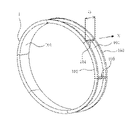
- the pipe length direction is the direction indicated by the arrow X extending in the pipe length direction of the pipe unit 10 in FIG. 2, and the circumferential direction is the circumferential direction of the circle of the pipe unit 10.
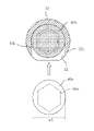
- FIG. 1 illustrates the structure of the rehabilitation tube segment 1 (hereinafter, simply referred to as a segment).
- the segment 1 includes an inner surface plate 101 constituting the inner peripheral surface of the rehabilitation pipe, side plates 102 and 103 having the same plate thickness vertically erected on both sides extending in the circumferential direction of the inner surface plate 101, and the pipe length of the inner surface plate 101. It is an integrally molded block-shaped member made of plastic composed of end plates 104 and 105 erected vertically at both ends extending in the direction.
- a plurality of inner plates 106, 107 having the same thickness as the side plates 102, 103 and having the same shape are arranged inside the side plates 102, 103. It is erected at equal intervals in parallel with 102 and 103.
- the segment 1 has a shape curved in an arc shape of 60 degrees which divides the circumference into a plurality of equal parts, for example, 6 equal parts, but the cross-sectional shape of the existing pipe, its size, or the repair of the existing pipe. Depending on the location, it can be a rectangular parallelepiped or a bent shape with a rounded shape at a right angle.
- a plurality of circular insertion holes 102a and 103a for passing the connecting bolt 11 are formed in the side plates 102 and 103 at equal intervals in the circumferential direction.
- a plurality of circular insertion holes 106a having a diameter smaller than the insertion holes 102a and 103a for passing the connecting bolts 11 are also formed in the inner plate 106 at equal intervals, and the connecting bolts can be inserted into the inner plate 107 and function as insertion holes.
- a plurality of notches 107a are formed at equal intervals.
- the insertion holes 102a, 103a, 106a, and the notch 107a have the same positions in the circumferential direction.
- the end plates 104 and 105 are members arranged between the side plates 102 and the side plates 103, and the end plates 104 and 105 have circular insertion holes for passing connecting bolts such as bolts that connect the segments 1 in the circumferential direction.
- a plurality of 104a and 105a are formed.
- segment 1 the end plate 105 and the end plate 104 of another segment are aligned and brought into contact with each other, the bolt 6 and the nut 7 (FIG. 3) are positioned in the insertion holes 104a and 105a, and the bolt 6 and the nut 7 are placed. By screwing, they can be connected in the circumferential direction.
- FIG. 2 By sequentially connecting the segments for one round in the circumferential direction, it is possible to assemble a ring-shaped pipe unit 10 having a predetermined width D perpendicular to the pipe length direction X as shown in FIG.
- the outer diameter of the pipe unit 10 is slightly smaller than the inner diameter of the existing pipe to be rehabilitated.
- the inner surface plate 101, the side plates 102, 103, the end plates 104, 105, which are the main structural members of the segment 1, are shown, and the reinforcing structure of the inner plates 106, 107 and the like avoids complexity. Therefore, the illustration is omitted.
- such pipe units 10 are sequentially connected in the pipe length direction.
- a plastic nut holding member for holding a nut 60 as shown in FIGS. 5a and 5b between the side plates 102 of the pipe unit segments 1a, 1b, and 1c and the inner plate 106 adjacent to the side plates 102.
- a plurality of 50s are attached.
- the connecting bolt 11 is connected to the side plates 102, 103 formed in the segment, the insertion holes 102a, 103a, 106a formed in the inner plate 106, and the notch 107a formed in the inner plate 107. It is connected in the pipe length direction by being inserted and screwed with the nut 60 held in the nut holding member 50.
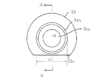
- the nut holding member 50 has a length t1 in the pipe length direction according to the distance t1'(FIG. 9) between the side plate 102 of the segment and the inner plate 106 adjacent thereto.
- a hollow columnar portion 51 is provided at one end thereof, a hollow cylindrical portion 52 is provided at the other end portion, and the columnar portions 53 and 54 having grooves 55 and 56 into which the nut 60 is press-fitted are provided.
- the cylindrical portions 51 and 52 coaxially have hollow portions 51a and 52a having a diameter r1 through which the connecting bolt 11 can be passed.
- the hollow portions 51a and 52a communicate with each other through the grooves 55 and 56 of the cylindrical portions 53 and 54, and a continuous hollow portion is formed in the nut holding member 50.
- the length t2 in the pipe length direction of the columnar portion 51 is set to be substantially the same as the plate thickness of the side plates 102, 103, and the inner plates 106, 107 of the segment, and the length in the pipe length direction of the columnar portions 53, 54 is the pipe length of the columnar portion 51. It is almost the same as the direction length t2.
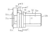
- the cylindrical portions 51 and 53 have a larger diameter than the other cylindrical portions 52 and 54, and when the nut holding member 50 is attached between the side plate 102 and the inner plate 106, the bottom of the cylindrical portions 51 and 53 is the inner surface plate 101. Since it collides with the upper part of the cylinder, the bottom portion is cut into a horizontal flat surface 51c (see also FIG. 10).
- a ring-shaped protrusion 51b is formed on the outer surface of the columnar portion 51 (the surface facing the side plate 102), and the outer diameter d1 thereof can be fitted into the insertion holes 102a and 103a in which the protrusion 51b is formed in the side plates 102 and 103. It is sized. Further, a ring-shaped protrusion 52b is formed on the outer surface of the columnar portion 52 (the surface facing the inner plate 106), and the outer diameter d2 thereof can be fitted into the insertion hole 106a in which the protrusion 52b is formed in the inner plate 106. It is sized.
- the length t3 of the nut holding member 50 including the protrusions 51b and 52b in the pipe length direction is such that the nut holding member 50 can be press-fitted between the side plate 102 of the segment and the inner plate 106 adjacent thereto.
- the protrusions 51b and 52b are fitted into the insertion holes 102a of the side plate 102 and the insertion holes 106a of the inner plate 106, and the nut holding member 50 is formed. It is prevented from falling out of the segment.
- the protrusions 51b and 52b may be formed in only one of them.
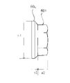
- the nut 60 press-fitted into the nut holding member 50 is a hexagon nut having a distance w2 between a circular flange portion 60a having a diameter w1 and two facing surfaces fixed thereto. It is configured as a flange nut composed of portions 60b.
- the diameter w1 of the flange portion 60a is larger than the diameter of the insertion holes 102a and 103a of the side plates 102 and 103, and the value is such that the nut 60 does not come out of the insertion holes 102a and 103a.
- the flange portion 60a and the hexagon nut portion 60b have lengths of s1 and s2 in the height direction of the nut, respectively, and the inside of the hexagon nut portion 60b is a screw portion to be screwed with the screw portion 11a of the connecting bolt 11. 60c is formed.
- the flange portion 60a of the nut 60 is press-fitted into the columnar portion 53 of the nut holding member 50, and a groove 55 extending in a direction orthogonal to the hollow portions 51a and 52a is formed.
- the groove 55 has a length s1'corresponding to the length s1 of the flange portion 60a in the pipe length direction (direction in which the nut holding member 50 extends), and as shown in FIG. 7a.
- the upper portion has an arc surface 55a corresponding to the circular shape of the flange portion 60a. Both sides of the groove 55 are vertical wall surfaces 55b and 55c, and the flange portion 60a can be inserted from the open lower portion. Since the groove 55 is formed following the columnar portion 51 in the pipe length direction, it is formed at a position separated from the outer surface of the columnar portion 51 by a distance of a thickness t2 of the side plate 102.
- a hexagon nut portion 60b is press-fitted into the columnar portions 53 and 54 of the nut holding member 50, and a groove 56 extending in a direction orthogonal to the hollow portions 51a and 52a is continuously formed in the groove 55.
- the groove 56 has a pipe length direction length s2'corresponding to the length s2 of the hexagon nut portion 60b, and a wall surface 56b separated by a distance w2' corresponding to the width w2 of the two facing surfaces of the hexagon nut portion 60b. , 56c (FIGS. 8a, 8b) are formed. Further, an arc surface 56a is formed on the upper portion of the groove 56.
- the hexagon nut portion 60b is inserted from the open lower portion of the groove 56 so that its two opposing surfaces are located between the two wall surfaces 56b and 56c. Further, on the wall surfaces 56b and 56c, protrusions 56d and 56e having a small triangular cross section extending in the pipe length direction are integrally formed with the wall surfaces 56b and 56c.
- the flange portion 60a and the hexagon nut portion 60b of the nut 60 are inserted from the open lower portions of the grooves 55 and 56, and the flange portion 60a hits the arc surface 55a of the groove 55. It is inserted until it touches. At this time, the nut 60 and the hollow portions 51a and 52a of the nut holding member 50 are coaxial, and the connecting bolt 11 can be screwed into the nut 60. Since protrusions 56d and 56e are formed on the wall surfaces 56b and 56c of the groove 56 into which the hexagon nut portion 60b is inserted, pressure input is required for inserting the hexagon nut portion 60b and press-fitting the protrusions 56d and 56e. This can prevent the protrusions 56d and 56e from being crushed and the hexagon nut portion 60b from falling out of the groove 56 due to the friction and pressure.
- the nut holding member 50 is integrally molded by injection molding using hard vinyl chloride (PVC) made of the same material as segment 1, but the material is not only hard vinyl chloride but also ABS resin and polypropylene (PP). ), Nylon, or the like, which may be a resin material that can withstand the strong alkaline component of the filler.
- PVC hard vinyl chloride
- PP polypropylene
- Nylon or the like, which may be a resin material that can withstand the strong alkaline component of the filler.
- the nut 60 When connecting the segments in the pipe length direction by using the nut holding member 50 as described above, the nut 60 is press-fitted in advance until the flange portion 60a abuts on the arc surface 55a of the groove 55 of the nut holding member 50, and the nut 60 is pressed. Is attached to the nut holding member 50. When the nut 60 is press-fitted, the hexagon nut portion 60b crushes the protrusions 56d and 56e formed in the groove 56, so that the nut 60 can be prevented from coming off from the grooves 55 and 56 due to the friction and pressure.
- the nut holding member 50 into which the nut 60 is press-fitted is aligned with the insertion hole 102a of the side plate 102 of the segment 1b and the insertion hole 106a of the inner plate 106 in the hollow portion 51a and the hollow portion 52a. As such, it is press-fitted between the side plate 102 and the inner plate 106 and attached. At this time, as shown in FIG.
- the protrusion 51b of the columnar portion 51 fits into the insertion hole 102a of the side plate 102 and enters the insertion hole 102a, and although not shown, the protrusion 52b of the columnar portion 52 Also, since it fits into the insertion hole 106a of the inner plate 106, the nut holding member 50 is prevented from coming off from the segment 1b.
- the nut holding member 50 is attached to a plurality of positions along the circumferential direction of the segment before transporting the segment to the construction site, for example, in a factory. In this way, the segment to which the nut holding member 50 is attached is carried into the manhole 20 as shown in FIG. 12, and is connected in the circumferential direction as shown in FIG. 2 to assemble the pipe unit 10. ..
- each segment of the pipe unit 10 is connected to the segment of another pipe unit in the pipe length direction.
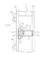
- 9 and 11 show the connection of the two segments 1a and 1b in the pipe length direction.
- the side plate 102 on one side of the segment 1b to which the nut holding member 50 is attached is aligned with the side plate 103 on the other side of the segment 1a connected to the segment 1b in the pipe length direction. Since the side plate 102 is formed with protrusions 102b for alignment, when these protrusions 102b are fitted into the holes 103b of the corresponding side plates 103, the inner peripheral surfaces of the inner surface plates 101 of the segments 1a and 1b coincide with each other. Further, the insertion holes 102a and 103a of the side plates 102 and 103 are aligned so that the connecting bolt 11 can pass through.
- the protrusions 102b and the holes 103b for alignment are not shown in FIGS. 1 and 3 in order to avoid complication in the drawings.
- the connecting bolt 11 is inserted from the insertion hole 102a of the side plate 102 formed in the segment 1a into the insertion hole 106a formed in the inner plate 106 and the notch (insertion hole) 107a formed in the inner plate 107. It is screwed into the nut 60 in the nut holding member 50 through the insertion hole 103a of the side plate 103 of the segment 1a and the insertion hole 102a of the side plate 102 of the segment 1b.
- the connecting bolt 11 is configured as a long bolt, and the connecting bolt 11 is nut 60 until the head portion 11b of the connecting bolt 11a abuts on the leftmost inner plate 106 adjacent to the side plate 102 of the segment 1a.
- a sufficient tightening force is generated on the abutted side plates 102 and 103, and both segments 1a and 1b can be firmly connected in the pipe length direction.
- the groove 55 into which the flange portion 70a of the nut 60 is inserted is separated from the side plate 102 of the segment 1b toward the inner plate 106 adjacent to the side plate 102 by a predetermined distance, for example, a distance of the thickness t2 of the side plate 102. Since it is formed at the position, the segment can withstand the tightening force even if a strong tightening force is generated when the segments are connected. Further, on both sides of the groove 56 into which the hexagon nut portion 60b of the nut 60 is inserted, wall surfaces 56b and 56c separated by a distance according to the widths of two facing surfaces of the hexagon nut portion 60b are formed, and the hexagon nut is formed. Since the two surfaces of the portion 60b are inserted along the wall surfaces 56b and 56c, it is possible to prevent the nut 60 from rotating even if the connecting bolt 11 rotates.
- FIG. 3 shows a state in which the segments 1c and 1b are already connected in the pipe length direction by the connecting bolt 11, and the segment 1a is connected to the segment 1b.
- the lower connecting bolt 11 of the segment 1a has already been screwed into the nut 60 of the segment 1b, and the upper connecting bolt 11 is now screwed into the nut 60 of the segment 1b, corresponding to the state shown in FIG. ..
- the pipe unit can be connected to an arbitrary length in the pipe length direction, and the inside of the existing pipe 21 can be connected.
- the rehabilitation pipe 40 can be laid in.
- a filler is filled between the outer circumference of the rehabilitation pipe 42 and the inner wall surface of the existing pipe 21, and the rehabilitation pipe and the existing pipe are integrated.
- the nut holding member 50 since the nut holding member 50 is attached so as to be offset from the adjacent segment in the circumferential direction, the arrangement of the connecting bolts 11 becomes zigzag, and the segments can be connected in the pipe length direction with sufficient strength. Become. Further, since the nut 60 is press-fitted into the groove formed in the nut holding member 50, the nut can be securely and easily attached. Further, even if the mounting position of the nut holding member 50 is incorrect, the nut holding member 50 can be easily removed by inserting a tool below the nut holding member 50 and lifting the nut holding member 50. Can be installed in the correct position.
- the nut holding member 50 has a shape in which cylindrical members having different diameters are continuous, but the cross section may be rectangular and a rectangular parallelepiped shape.
- the type of nut is a nut with a flange, but a nut without a flange may be used.
- the nut holding member 50 was attached so that the open ends of the grooves 55 and 56 into which the nut 60 was inserted face the upper surface of the inner surface plate 101 of the segment, but the nut holding member 50 was rotated 90 degrees in the left-right direction, that is, the inner surface plate 101. It may be mounted so as to face the direction along the upper surface.
Landscapes
- Engineering & Computer Science (AREA)
- General Engineering & Computer Science (AREA)
- Mining & Mineral Resources (AREA)
- Architecture (AREA)
- Civil Engineering (AREA)
- Structural Engineering (AREA)
- Mechanical Engineering (AREA)
- Life Sciences & Earth Sciences (AREA)
- General Life Sciences & Earth Sciences (AREA)
- Geochemistry & Mineralogy (AREA)
- Geology (AREA)
- Lining And Supports For Tunnels (AREA)
- Lining Or Joining Of Plastics Or The Like (AREA)
- Orthopedics, Nursing, And Contraception (AREA)
Abstract
側板102、103と、両側板の内側に内部板106、107を複数有するセグメントが周方向と管長方向に連結されて既設管内に更生管が構築される。セグメント1bの一方側の側板102とそれに隣接する内部板106間に、連結ボルト11と螺合するナット60を内部に保持するプラスチック製のナット保持部材50が取り付けられる。連結ボルトをナットに螺合させて、螺合による締付けによりセグメント1a、1bが管長方向に連結される。ナット保持部材に溝が形成され、ナットが該溝に圧入されてナット保持部材に保持される。
Description
本発明は、内周面を構成する内面板と、該内面板の周縁に立設された側板並びに端板とをプラスチックによって一体に形成してなるセグメントを、周方向並びに管長方向に連結して既設管内に更生管を敷設する管更生工法に関する。
地中に埋設された下水管等の管路が老朽化した場合、該管路を地中から掘出することなく、その内周面にライニングを施して管路を補修する管ライニング工法が提案され、既に実用に供されている。
大口径の管路を更生する場合には、内周面を構成する内面板と、内面板の周縁に立設された側板並びに端板とをプラスチックによって一体に形成してなるセグメントが用いられる。セグメントは周方向に連結されて管ユニットが組み立てられ、該管ユニットが連結ボルトを介して管長方向に連結されて既設管内に更生管が組み立てられる。
下記特許文献1には、セグメントの両側板間を管長方向に渡って延びる長い連結ボルトを用い、この連結ボルトをセグメントに固定するとともに、連結ボルトを互いに連結してセグメントを管長方向に連結する構成が記載されている。
下記特許文献2には、一方のセグメントにナットを固定し、連結ボルトを他方のセグメントを通して該一方のセグメントに固定されたナットに螺合することにより、両セグメントを管長方向に連結する構成が記載されている。
しかしながら、特許文献1に記載されたようなセグメントの連結方法では、連結ボルトが互いに管長方向に連結され、一本に連結された長い棒状の部材となり、各セグメントが管長方向に連結されるので、連結ボルトが存在するセグメント部分は堅固に結合されるが、連結ボルトが存在しない部分では、セグメントを十分な強度をもって管長方向に結合することはできない。
一方、特許文献2に記載されたセグメントの連結方法では、ナットを周方向にずらして固定することにより、連結ボルトの配置がジグザグ状になるので、セグメントを十分な強度をもって管長方向に結合することが可能になる。しかし、ナットがセグメントの側板とそれに隣接する内部板に渡って取り付けられる長いナットとなっているので、連結ボルトのネジ部と螺合するネジ部を長いナットの内部全長に渡って形成する必要があり、高価なナットを必要とする、という問題があった。
また、特許文献2に記載されたナットは管長方向に長いので、その一端をセグメントの側板に隣接する内部板にボルト締めすることにより固定する必要があり、ナット取り付けにトルク管理された専用ツールが必要となる。さらに、ナット取り付け位置が間違っていた場合には、ボルト締めを緩め、改めて正しい位置に取り付ける必要があり、取り換え作業に時間を要する、という問題があった。
本発明は、このような問題点を解決するためになされたもので、安価にセグメントを管長方向に連結することが可能な管更生工法を提供することを課題とする。
本発明は、
内面板と、該内面板の両側に立設された側板と、側板の内側で内面板の上面に立設された内部板を複数有するセグメントを、周方向と管長方向に連結して既設管内に更生管を敷設する管更生工法であって、
ナットを内部に保持し、前記ナットと螺合する連結ボルトを通過させる中空部を備えたプラスチック製のナット保持部材を、一方のセグメントの側板と該側板に隣接する内部板間に取り付ける工程と、
前記一方のセグメントと、該一方のセグメントと管長方向に連結される他方のセグメントを位置合わせする工程と、
連結ボルトを前記ナットに螺合せ、該一方と他方のセグメントを管長方向に連結する工程と、
を備え、
前記ナット保持部材に、中空部に直交する方向に延びる溝が形成され、前記ナットが該溝に圧入されてナット保持部材に保持されることを特徴とする。
本発明によれば、セグメントの一方側の側板と該側板に隣接する内部板間に取り付けられたナット保持部材の内部にナットが保持されるので、ナットの管長方向長さを、側板とその側板に隣接する内部板間の距離より小さくすることができ、小型で安価なナットを使用することができる。また、ナットは、ナット保持部材に形成された溝に圧入されるので、ナットの取り付けが確実で簡単になるとともに、ナット保持部材の着脱が容易になるので、ナットの取り付け位置が間違っていた場合でも、簡単にやり直しができる、という効果が得られる。
以下に本発明を、添付図面に示す実施例に基づいて説明する。本発明は、下水管、上水管、トンネル、あるいは農業用水路などの大口径の既設管を更生あるいは修復するのに適している。実施例では、更生管は、管長方向に直交する断面形状が円形として説明されるが、矩形など円形以外の形状の更生管にも本発明を適用できることは勿論である。更に、断面形状が管として閉じた形状でなく、例えば馬蹄形や半円形、凹字形など片側が開いた形状である場合にも管と見なして本発明を適用することができる。
この明細書において、管長方向とは図2で管ユニット10の管の長さ方向に延びる矢印Xで示した方向を、周方向とは管ユニット10の円の周方向をいう。
図1には、更生管用セグメント1(以下、単にセグメントという)の構造が図示されている。セグメント1は、更生管の内周面を構成する内面板101と、該内面板101の周方向に延びる両側に垂直に立設された同じ板厚の側板102、103と、内面板101の管長方向に延びる両端に垂直に立設された端板104、105とからなるプラスチックでできた一体成形のブロック状の部材である。
内面板101の上面には、セグメント1の機械的強度を補強するために、側板102、103の内側に、側板102、103と同じ板厚並びに同様な形状の複数の内部板106、107が側板102、103と平行に等間隔に立設される。
セグメント1は、円周を複数等分する所定角度、例えば6等分する60度の円弧状に湾曲した形状となっているが、既設管の断面形状、あるいはその大きさ、あるいは既設管の補修箇所に応じて、直方体あるいは直角に丸みを付けて折り曲げた形などにすることもできる。
側板102、103には、セグメント1を管長方向に連結するために、連結ボルト11(図3)を通すための円形の挿通穴102a、103aが周方向に等間隔に複数形成される。内部板106にも、連結ボルト11を通すための挿通穴102a、103aより小径の円形の挿通穴106aが等間隔に複数形成され、内部板107には、連結ボルトが挿入でき挿通穴として機能する切り欠き107aが等間隔に複数形成される。これらの挿通穴102a、103a、106a、並びに切り欠き107aは、それぞれ周方向の位置が一致している。
端板104、105は、側板102と側板103の間に配置される部材で、端板104、105には、セグメント1を周方向に連結するボルト等の連結ボルトを通すための円形の挿通穴104a、105aが複数形成される。
セグメント1はその端板105と他のセグメントの端板104を位置合わせして当接させ、ボルト6とナット7(図3)を挿通穴104a、105aに位置決めして、ボルト6とナット7を螺合させることにより周方向に連結させることができる。
セグメントを順次周方向に一周分連結させると、図2に示すような管長方向Xに垂直に所定幅Dを有するリング状の管ユニット10を組み立てることができる。管ユニット10は、その外径が更生すべき既設管の内径より少し小さな値となっている。なお、図2では、セグメント1の主要な構造部材である内面板101、側板102、103、端板104、105が図示されていて、内部板106、107等の補強構造は、煩雑さを避けるために、図示が省略されている。
このような管ユニット10は、図3に示したように、順次管長方向に連結される。図3において、管ユニットのセグメント1a、1b、1cの側板102と側板102に隣接する内部板106間には、図5a、図5bに図示したようなナット60を保持するプラスチック製のナット保持部材50が複数取り付けられる。各セグメント1a、1b、1cは、連結ボルト11を、セグメントに形成された側板102、103、内部板106に形成された挿通穴102a、103a、106a、内部板107に形成された切り欠き107aに挿通し、ナット保持部材50内に保持されたナット60と螺合することにより管長方向に連結される。
ナット保持部材50は、図4a、図4b、図4cに示したように、セグメントの側板102とそれに隣接する内部板106間の距離t1’(図9)に応じた管長方向長さt1を有し、一方端部に中空な円柱部51と、他方端部に中空な円柱部52と、ナット60が圧入される溝55、56が形成された円柱部53、54とを備えている。円柱部51、52は、それぞれ連結ボルト11を通すことができる径r1の中空部51a、52aを同軸に有する。中空部51a、52aは、円柱部53、54の溝55、56を介して連通しており、ナット保持部材50には、連続した中空部が形成される。
円柱部51の管長方向長さt2は、セグメントの側板102、103、内部板106、107の板厚とほぼ同じに設定され、円柱部53、54の管長方向長さは、円柱部51の管長方向長さt2とほぼ同一になっている。なお、円柱部51、53は、他の円柱部52、54より径が大きく、ナット保持部材50が側板102と内部板106間に取り付けられたとき、円柱部51、53の底部が内面板101の上部と衝突するので、該底部が切断されて水平な平面51cになっている(図10も参照)。
円柱部51の外表面(側板102に向かう面)には、リング状突起51bが形成され、その外径d1は、突起51bが側板102、103に形成された挿通穴102a、103aに嵌合できる大きさになっている。また、円柱部52の外表面(内部板106に向かう面)には、リング状突起52bが形成され、その外径d2は、突起52bが内部板106に形成された挿通穴106aに嵌合できる大きさになっている。
突起51b、52bを含めたナット保持部材50の管長方向の長さt3は、ナット保持部材50をセグメントの側板102とそれに隣接する内部板106間に圧入できる長さになっている。ナット保持部材50を、側板102と内部板106間に圧入して取り付けると、突起51b、52bが側板102の挿通穴102aと内部板106の挿通穴106aに嵌合して、ナット保持部材50がセグメントから抜け落ちることが防止される。なお、突起51b、52bは、いずれか一方だけにすることもできる。
ナット保持部材50に圧入されるナット60は、図5a、5bに図示したように、径w1の円形なフランジ部60aとこれに固定されるそれぞれ対向する2面間の距離がw2の6角ナット部60bからなるフランジナットとして構成される。フランジ部60aの径w1は、側板102、103の挿通穴102a、103aの径より大きく、ナット60が挿通穴102a、103aから抜け出ないような値になっている。フランジ部60a、6角ナット部60bは、それぞれナットの高さ方向にs1、s2の長さを有し、6角ナット部60b内には、連結ボルト11のネジ部11aと螺合するネジ部60cが形成される。
ナット保持部材50の円柱部53には、ナット60のフランジ部60aが圧入され、中空部51a、52aに直交する方向に延びる溝55が形成される。溝55は、図6bに示したように、管長方向(ナット保持部材50が延びる方向)に、フランジ部60aの長さs1に応じた長さs1’を有するとともに、図7aに図示したように、フランジ部60aの円形形状に相当する円弧面55aを上部に有する。溝55の両側は垂直な壁面55b、55cになっていて、開放した下部からフランジ部60aが挿入できるようになっている。溝55は、管長方向に円柱部51に続いて形成されるので、円柱部51の外表面から側板102の厚さt2の距離隔てた位置に形成される。
また、ナット保持部材50の円柱部53、54には、6角ナット部60bが圧入され、中空部51a、52aに直交する方向に延びる溝56が溝55に連続して形成される。溝56には、6角ナット部60bの長さs2に応じた管長方向長さs2’を有するとともに、6角ナット部60bの対向する2面の幅w2に応じた距離w2’離間した壁面56b、56c(図8a、図8b)が形成される。、また、溝56には、円弧面56aが上部に形成される。6角ナット部60bは、その対向する2面が両壁面56b、56c間に位置するように、溝56の開放した下部から挿入される。また、壁面56b、56cには、断面が3角形の小さな管長方向に延びる突起56d、56eが壁面56b、56cと一体に形成される。
ナット60のフランジ部60aと6角ナット部60bは、図7b、図8bに示したように、溝55、56の開放した下方部から差し込まれ、フランジ部60aが溝55の円弧面55aに当接するまで挿入される。このとき、ナット60、ナット保持部材50の中空部51a、52aは同軸となり、連結ボルト11をナット60に螺合させることができる。6角ナット部60bが挿入される溝56の壁面56b、56cには、突起56d、56eが形成されているので、6角ナット部60bの挿入には、圧入力が必要になるとともに、その圧入により突起56d、56eが押しつぶされて、その摩擦と圧力で6角ナット部60bが溝56から抜け落ちてしまうのを防止することができる。
なお、ナット保持部材50は、セグメント1と同じ材質の硬質塩化ビニル(PVC)を用いて射出成型により一体に成形されるが、その材質は、硬質塩化ビニルだけではなく、ABS樹脂、ポリプロピレン(PP)、ナイロン等、充填材の強アルカリ成分に耐えられる樹脂材料であってもよい。
上述したようなナット保持部材50を用いてセグメントを管長方向に連結する場合、予めナット60を、そのフランジ部60aがナット保持部材50の溝55の円弧面55aに当接するまで圧入し、ナット60をナット保持部材50に取り付けておく。ナット60の圧入時、6角ナット部60bが溝56に形成された突起56d、56eを押しつぶすので、その摩擦と圧力でナット60が溝55、56から外れてしまうのを防止することができる。
続いて、図9に図示したように、ナット60が圧入されたナット保持部材50を、中空部51a、中空部52aがセグメント1bの側板102の挿通穴102a、内部板106の挿通穴106aと整合するように、側板102と内部板106間に圧入して取り付ける。このとき、図10に示したように、円柱部51の突起51bは、側板102の挿通穴102aと嵌合して挿通穴102a内に入り込み、また、図示はないが、円柱部52の突起52bも、内部板106の挿通穴106aに嵌合するので、ナット保持部材50がセグメント1bから抜け落ちることが防止される。
なお、ナット保持部材50は、セグメントを工事現場に搬送する前、例えば工場内で、セグメントの周方向に沿った複数の位置に取り付けられる。このように、ナット保持部材50が取り付けられたセグメントは、図12に示したように、マンホール20内に搬入され、図2に図示したように、周方向に連結されて管ユニット10が組み立てられる。
続いて、管ユニット10の各セグメントは、他の管ユニットのセグメントと管長方向に連結される。図9、図11は、2つのセグメント1a、1bの管長方向の連結を説明する。
図11に示したように、ナット保持部材50が取り付けられたセグメント1bの一方側の側板102と、セグメント1bと管長方向に連結されるセグメント1aの他方側の側板103を位置合わせする。側板102には、位置合わせ用の突起102bが形成されているので、これらの突起102bを対応する側板103の穴103bに嵌入すると、セグメント1a、1bの内面板101の内周面が一致し、また、連結ボルト11が通過できるように、側板102、103の挿通穴102a、103aが整合する。なお、位置合わせ用の突起102b並び穴103bは、図の煩雑さを避けるために、図1、図3などには、図示が省略されている。
続いて、連結ボルト11を、セグメント1aに形成された側板102の挿通穴102aから内部板106に形成された挿通穴106a、内部板107に形成された切り欠き(挿通穴)107aに挿通し、セグメント1aの側板103の挿通穴103a、セグメント1bの側板102の挿通穴102aに通してナット保持部材50内のナット60と螺合させる。
本実施例では、連結ボルト11は長ボルトとして構成されており、連結ボルト11aの頭部11bがセグメント1aの側板102に隣接する最左端の内部板106に当接するまで、連結ボルト11をナット60にねじ込むと、突き合わされた側板102、103に十分な締付力が発生し、両セグメント1a、1bを管長方向に堅固に連結することができる。
本実施例では、ナット60のフランジ部70aが挿入される溝55がセグメント1bの側板102から該側板102に隣接する内部板106に向かって所定距離、例えば側板102の厚さt2の距離隔てた位置に形成されるので、セグメントの連結時、強い締付力が発生しても、セグメントは、その締付力に耐えることができる。また、ナット60の6角ナット部60bが挿入される溝56の両側には、6角ナット部60bの対向する2面の幅に応じた距離離間した壁面56b、56cが形成され、6角ナット部60bは、2面が壁面56b、56cに沿って挿入されるので、連結ボルト11が回転しても、ナット60の供回りを防止することができる。
図3には、セグメント1cと1bは、連結ボルト11により既に管長方向に連結されており、セグメント1bにセグメント1aを連結する状態が示されている。セグメント1aの下の連結ボルト11は、既にセグメント1bのナット60にねじ込まれており、上の連結ボルト11は、これからセグメント1bのナット60にねじ込まれる状態で、図11に図示した状態に対応する。
このようにして、管ユニットのセグメントを、既に連結されている他の管ユニットのセグメントと管長方向に連結することにより、管ユニットを管長方向に任意の長さに連結して、既設管21内に更生管40を敷設することができる。更生管42が所定長さになると、更生管42の外周と既設管21の内壁面との間に充填材が充填され、更生管と既設管が一体化される。
本実施例では、ナット保持部材50は隣接するセグメントとは周方向にずらして取り付けられるので、連結ボルト11の配置がジグザグ状になり、セグメントを十分な強度をもって管長方向に結合することが可能になる。また、ナット60は、ナット保持部材50に形成された溝に圧入されるので、ナットの取り付けが確実で簡単になる。またナット保持部材50の取り付け位置が間違っていた場合でも、工具をナット保持部材50の下方に挿入してナット保持部材50を持ち上げることにより簡単に取り外すことができるので、ナット保持部材50を簡単に正しい位置に取り付けることができる。
なお、本実施例では、ナット保持部材50は、径の異なる円柱部材を連続させた形状となっているが、断面が矩形で直方体の形状をしていてもよい。また、ナットの種類は、フランジ付きナットとなっているが、フランジなしのナットでもよい。また、ナット保持部材50は、ナット60が挿入される溝55、56の開放端がセグメントの内面板101の上面に向くように、取り付けたが、90度回転した左右方向、つまり内面板101の上面に沿った方向に向くように、取り付けてもよい。
1 セグメント
10 管ユニット
11 連結ボルト
20 マンホール
21 既設管
40 更生管
50 ナット保持部材
51a、52a 中空部
55、56 溝
60 ナット
101 内面板
102、103 側板
104、105 端板
106、107 内部板
10 管ユニット
11 連結ボルト
20 マンホール
21 既設管
40 更生管
50 ナット保持部材
51a、52a 中空部
55、56 溝
60 ナット
101 内面板
102、103 側板
104、105 端板
106、107 内部板
Claims (7)
- 内面板と、該内面板の両側に立設された側板と、側板の内側で内面板の上面に立設された内部板を複数有するセグメントを、周方向と管長方向に連結して既設管内に更生管を敷設する管更生工法であって、
ナットを内部に保持し、前記ナットと螺合する連結ボルトを通過させる中空部を備えたプラスチック製のナット保持部材を、一方のセグメントの側板と該側板に隣接する内部板間に取り付ける工程と、
前記一方のセグメントと、該一方のセグメントと管長方向に連結される他方のセグメントを位置合わせする工程と、
連結ボルトを前記ナットに螺合せ、該一方と他方のセグメントを管長方向に連結する工程と、
を備え、
前記ナット保持部材に、中空部に直交する方向に延びる溝が形成され、前記ナットが該溝に圧入されてナット保持部材に保持されることを特徴とする管更生工法。 - 前記ナットが、フランジ部と該フランジ部に固定された6角ナット部とからなるフランジナットであり、前記ナット保持部材にフランジ部が挿入される溝と6角ナット部が挿入される溝が形成されることを特徴とする請求項1に記載の管更生工法。
- 前記ナットのフランジ部が挿入される溝は、ナット保持部材の一端から所定の距離隔てた位置に形成されることを特徴とする請求項2に記載の管更生工法。
- 前記ナットの6角ナット部が挿入される溝には、6角ナット部の長さに応じた管長方向長さを有し、6角ナット部の対向する2面の幅に応じた距離離間した壁面が形成され、該6角ナット部は、その対向する2面が壁面間に位置するように、溝に挿入されることを特徴とする請求項2に記載の管更生工法。
- 前記6角ナット部が挿入される溝の一方あるいは両方の壁面に突起が形成されており、6角ナット部が該溝に挿入されるとき、該突起が押しつぶされて押しつぶされた突起との摩擦により6角ナット部が溝から抜け落ちるのが防止されることを特徴とする請求項4に記載の管更生工法。
- 前記ナット保持部材の側板に向かう面には、管長方向に突出するリング状の突起が形成されており、前記ナット保持部材は、該突起が該側板に形成された連結ボルトを通すことができる挿通穴に嵌合するように、取り付けられることを特徴とする請求項1に記載の管更生工法。
- 前記ナット保持部材の内部板に向かう面には、管長方向に突出するリング状の突起が形成されており、前記ナット保持部材は、該突起が該内部板に形成された連結ボルトを通すことができる挿通穴に嵌合するように、取り付けられることを特徴とする請求項1に記載の管更生工法。
Priority Applications (1)
| Application Number | Priority Date | Filing Date | Title |
|---|---|---|---|
| JP2022563608A JPWO2022107457A1 (ja) | 2020-11-18 | 2021-09-30 |
Applications Claiming Priority (2)
| Application Number | Priority Date | Filing Date | Title |
|---|---|---|---|
| JP2020-191966 | 2020-11-18 | ||
| JP2020191966 | 2020-11-18 |
Publications (1)
| Publication Number | Publication Date |
|---|---|
| WO2022107457A1 true WO2022107457A1 (ja) | 2022-05-27 |
Family
ID=81708883
Family Applications (1)
| Application Number | Title | Priority Date | Filing Date |
|---|---|---|---|
| PCT/JP2021/036030 WO2022107457A1 (ja) | 2020-11-18 | 2021-09-30 | 管更生工法 |
Country Status (3)
| Country | Link |
|---|---|
| JP (1) | JPWO2022107457A1 (ja) |
| TW (1) | TW202227742A (ja) |
| WO (1) | WO2022107457A1 (ja) |
Citations (6)
| Publication number | Priority date | Publication date | Assignee | Title |
|---|---|---|---|---|
| JPH0362213U (ja) * | 1989-10-23 | 1991-06-18 | ||
| JPH1068293A (ja) * | 1996-08-28 | 1998-03-10 | Hitachi Zosen Corp | セグメントの締結装置 |
| KR20060023504A (ko) * | 2004-09-09 | 2006-03-14 | 대한주택공사 | 천장 마감패널 설치용 너트홀더 및 체결너트 |
| JP2009243531A (ja) * | 2008-03-28 | 2009-10-22 | Ishikawajima Constr Materials Co Ltd | ナットホルダー、継手部構造及びコンクリート構造物 |
| JP2011012803A (ja) * | 2009-06-03 | 2011-01-20 | Shonan Plastic Mfg Co Ltd | 既設管の更生工法 |
| WO2016088168A1 (ja) * | 2014-12-01 | 2016-06-09 | 株式会社湘南合成樹脂製作所 | 既設管の更生工法 |
-
2021
- 2021-09-30 TW TW110136451A patent/TW202227742A/zh unknown
- 2021-09-30 JP JP2022563608A patent/JPWO2022107457A1/ja active Pending
- 2021-09-30 WO PCT/JP2021/036030 patent/WO2022107457A1/ja active Application Filing
Patent Citations (6)
| Publication number | Priority date | Publication date | Assignee | Title |
|---|---|---|---|---|
| JPH0362213U (ja) * | 1989-10-23 | 1991-06-18 | ||
| JPH1068293A (ja) * | 1996-08-28 | 1998-03-10 | Hitachi Zosen Corp | セグメントの締結装置 |
| KR20060023504A (ko) * | 2004-09-09 | 2006-03-14 | 대한주택공사 | 천장 마감패널 설치용 너트홀더 및 체결너트 |
| JP2009243531A (ja) * | 2008-03-28 | 2009-10-22 | Ishikawajima Constr Materials Co Ltd | ナットホルダー、継手部構造及びコンクリート構造物 |
| JP2011012803A (ja) * | 2009-06-03 | 2011-01-20 | Shonan Plastic Mfg Co Ltd | 既設管の更生工法 |
| WO2016088168A1 (ja) * | 2014-12-01 | 2016-06-09 | 株式会社湘南合成樹脂製作所 | 既設管の更生工法 |
Also Published As
| Publication number | Publication date |
|---|---|
| JPWO2022107457A1 (ja) | 2022-05-27 |
| TW202227742A (zh) | 2022-07-16 |
Similar Documents
| Publication | Publication Date | Title |
|---|---|---|
| JP5457130B2 (ja) | 既設管の更生工法 | |
| US7341280B2 (en) | Rehabilitating pipe and method for laying a rehabilitating pipe | |
| US9797539B1 (en) | Pipe rehabilitation method | |
| US7083360B2 (en) | Method for rehabilitating an existing pipe | |
| JP6555957B2 (ja) | 管更生工法 | |
| JP5235123B2 (ja) | セグメントの連結方法及び連結具 | |
| US20210041050A1 (en) | Pipe rehabilitation method | |
| WO2022107457A1 (ja) | 管更生工法 | |
| US9194528B2 (en) | Pipe rehabilitation method | |
| US9068686B2 (en) | Rehabilitation pipe and pipe rehabilitation method | |
| EP4137730A1 (en) | Pipe rehabilitation construction method | |
| WO2016088168A1 (ja) | 既設管の更生工法 | |
| JP4541946B2 (ja) | 既設管路の補修構造 | |
| US20240151342A1 (en) | Pipe rehabilitation method | |
| JP2009108484A (ja) | セグメントの連結方法 | |
| JP2021110372A (ja) | 更生管及び管更生工法 | |
| JP2022083254A (ja) | 剥離防止部材及びこれを備えた管路の内張構造 |
Legal Events
| Date | Code | Title | Description |
|---|---|---|---|
| 121 | Ep: the epo has been informed by wipo that ep was designated in this application |
Ref document number: 21894332 Country of ref document: EP Kind code of ref document: A1 |
|
| ENP | Entry into the national phase |
Ref document number: 2022563608 Country of ref document: JP Kind code of ref document: A |
|
| NENP | Non-entry into the national phase |
Ref country code: DE |
|
| 122 | Ep: pct application non-entry in european phase |
Ref document number: 21894332 Country of ref document: EP Kind code of ref document: A1 |