WO2022107273A1 - 回転子、電動機、送風機、空気調和装置、及び回転子の製造方法 - Google Patents
回転子、電動機、送風機、空気調和装置、及び回転子の製造方法 Download PDFInfo
- Publication number
- WO2022107273A1 WO2022107273A1 PCT/JP2020/043191 JP2020043191W WO2022107273A1 WO 2022107273 A1 WO2022107273 A1 WO 2022107273A1 JP 2020043191 W JP2020043191 W JP 2020043191W WO 2022107273 A1 WO2022107273 A1 WO 2022107273A1
- Authority
- WO
- WIPO (PCT)
- Prior art keywords
- rotor
- permanent magnet
- rotor core
- core
- radial
- Prior art date
- Legal status (The legal status is an assumption and is not a legal conclusion. Google has not performed a legal analysis and makes no representation as to the accuracy of the status listed.)
- Ceased
Links
Images


Classifications
-
- H—ELECTRICITY
- H02—GENERATION; CONVERSION OR DISTRIBUTION OF ELECTRIC POWER
- H02K—DYNAMO-ELECTRIC MACHINES
- H02K1/00—Details of the magnetic circuit
- H02K1/06—Details of the magnetic circuit characterised by the shape, form or construction
- H02K1/22—Rotating parts of the magnetic circuit
- H02K1/27—Rotor cores with permanent magnets
- H02K1/2706—Inner rotors
- H02K1/272—Inner rotors the magnetisation axis of the magnets being perpendicular to the rotor axis
- H02K1/274—Inner rotors the magnetisation axis of the magnets being perpendicular to the rotor axis the rotor consisting of two or more circumferentially positioned magnets
- H02K1/2753—Inner rotors the magnetisation axis of the magnets being perpendicular to the rotor axis the rotor consisting of two or more circumferentially positioned magnets the rotor consisting of magnets or groups of magnets arranged with alternating polarity
- H02K1/276—Magnets embedded in the magnetic core, e.g. interior permanent magnets [IPM]
-
- F—MECHANICAL ENGINEERING; LIGHTING; HEATING; WEAPONS; BLASTING
- F04—POSITIVE - DISPLACEMENT MACHINES FOR LIQUIDS; PUMPS FOR LIQUIDS OR ELASTIC FLUIDS
- F04D—NON-POSITIVE-DISPLACEMENT PUMPS
- F04D19/00—Axial-flow pumps
- F04D19/002—Axial flow fans
-
- F—MECHANICAL ENGINEERING; LIGHTING; HEATING; WEAPONS; BLASTING
- F04—POSITIVE - DISPLACEMENT MACHINES FOR LIQUIDS; PUMPS FOR LIQUIDS OR ELASTIC FLUIDS
- F04D—NON-POSITIVE-DISPLACEMENT PUMPS
- F04D25/00—Pumping installations or systems
- F04D25/02—Units comprising pumps and their driving means
- F04D25/06—Units comprising pumps and their driving means the pump being electrically driven
-
- F—MECHANICAL ENGINEERING; LIGHTING; HEATING; WEAPONS; BLASTING
- F04—POSITIVE - DISPLACEMENT MACHINES FOR LIQUIDS; PUMPS FOR LIQUIDS OR ELASTIC FLUIDS
- F04D—NON-POSITIVE-DISPLACEMENT PUMPS
- F04D29/00—Details, component parts, or accessories
- F04D29/58—Cooling; Heating; Diminishing heat transfer
- F04D29/582—Cooling; Heating; Diminishing heat transfer specially adapted for elastic fluid pumps
-
- F—MECHANICAL ENGINEERING; LIGHTING; HEATING; WEAPONS; BLASTING
- F24—HEATING; RANGES; VENTILATING
- F24F—AIR-CONDITIONING; AIR-HUMIDIFICATION; VENTILATION; USE OF AIR CURRENTS FOR SCREENING
- F24F1/00—Room units for air-conditioning, e.g. separate or self-contained units or units receiving primary air from a central station
- F24F1/0007—Indoor units, e.g. fan coil units
- F24F1/0018—Indoor units, e.g. fan coil units characterised by fans
-
- H—ELECTRICITY
- H02—GENERATION; CONVERSION OR DISTRIBUTION OF ELECTRIC POWER
- H02K—DYNAMO-ELECTRIC MACHINES
- H02K1/00—Details of the magnetic circuit
- H02K1/06—Details of the magnetic circuit characterised by the shape, form or construction
- H02K1/12—Stationary parts of the magnetic circuit
- H02K1/14—Stator cores with salient poles
- H02K1/146—Stator cores with salient poles consisting of a generally annular yoke with salient poles
- H02K1/148—Sectional cores
-
- H—ELECTRICITY
- H02—GENERATION; CONVERSION OR DISTRIBUTION OF ELECTRIC POWER
- H02K—DYNAMO-ELECTRIC MACHINES
- H02K1/00—Details of the magnetic circuit
- H02K1/06—Details of the magnetic circuit characterised by the shape, form or construction
- H02K1/22—Rotating parts of the magnetic circuit
- H02K1/28—Means for mounting or fastening rotating magnetic parts on to, or to, the rotor structures
-
- H—ELECTRICITY
- H02—GENERATION; CONVERSION OR DISTRIBUTION OF ELECTRIC POWER
- H02K—DYNAMO-ELECTRIC MACHINES
- H02K15/00—Processes or apparatus specially adapted for manufacturing, assembling, maintaining or repairing of dynamo-electric machines
- H02K15/02—Processes or apparatus specially adapted for manufacturing, assembling, maintaining or repairing of dynamo-electric machines of stator or rotor bodies
- H02K15/03—Processes or apparatus specially adapted for manufacturing, assembling, maintaining or repairing of dynamo-electric machines of stator or rotor bodies having permanent magnets
-
- H—ELECTRICITY
- H02—GENERATION; CONVERSION OR DISTRIBUTION OF ELECTRIC POWER
- H02K—DYNAMO-ELECTRIC MACHINES
- H02K15/00—Processes or apparatus specially adapted for manufacturing, assembling, maintaining or repairing of dynamo-electric machines
- H02K15/12—Impregnating, moulding insulation, heating or drying of windings, stators, rotors or machines
-
- H—ELECTRICITY
- H02—GENERATION; CONVERSION OR DISTRIBUTION OF ELECTRIC POWER
- H02K—DYNAMO-ELECTRIC MACHINES
- H02K21/00—Synchronous motors having permanent magnets; Synchronous generators having permanent magnets
- H02K21/12—Synchronous motors having permanent magnets; Synchronous generators having permanent magnets with stationary armatures and rotating magnets
- H02K21/14—Synchronous motors having permanent magnets; Synchronous generators having permanent magnets with stationary armatures and rotating magnets with magnets rotating within the armatures
- H02K21/16—Synchronous motors having permanent magnets; Synchronous generators having permanent magnets with stationary armatures and rotating magnets with magnets rotating within the armatures having annular armature cores with salient poles
-
- H—ELECTRICITY
- H02—GENERATION; CONVERSION OR DISTRIBUTION OF ELECTRIC POWER
- H02K—DYNAMO-ELECTRIC MACHINES
- H02K2213/00—Specific aspects, not otherwise provided for and not covered by codes H02K2201/00 - H02K2211/00
- H02K2213/03—Machines characterised by numerical values, ranges, mathematical expressions or similar information
Definitions
- the present disclosure relates to a rotor, a motor, a blower, an air conditioner, and a method for manufacturing a rotor.
- Patent Document 1 As a rotor of an electric motor, a rotor having a permanent magnet and a rotor core to which the permanent magnet is attached is known. See, for example, Patent Document 1.
- the rotor core of Patent Document 1 has a magnet insertion portion into which a permanent magnet is inserted.
- the permanent magnet is brought into close contact with one of the radial inward surface and the radial outward surface of the magnet insertion portion by the magnetic attraction, and the permanent magnet and the permanent magnet. A gap is formed between the surface and the other surface. In this case, there is a problem that the amount of magnetic flux of the magnetic flux of the permanent magnet flowing from the rotor to the stator of the motor decreases.
- the purpose of this disclosure is to prevent a decrease in the amount of magnetic flux of the magnetic flux of a permanent magnet.
- the rotor includes a first rotor core, a first surface abutting on a first radial outward surface of the first rotor core, and a radial outward first.
- a plurality of permanent magnets having two surfaces and a plurality of second rotor cores having radial inward surfaces, wherein the radial inward surfaces of the plurality of second rotor cores are.
- FIG. 1 It is a top view which shows a part of the structure of the electric motor which concerns on Embodiment 1.
- FIG. It is a top view which shows a part of the structure of the rotor of the electric motor shown in FIG. It is a side view which shows the structure of the rotor which concerns on Embodiment 1.
- FIG. 3 is an enlarged plan view showing the configuration around the tip of the teeth of the stator core shown in FIG. 1.
- (A) to (C) are schematic diagrams showing an example of a manufacturing process of an intermediate structure of a rotor. It is a top view which shows the structure of the rotor which concerns on the modification 1 of Embodiment 1.
- FIG. 1 It is a top view which shows the structure of the rotor which concerns on the modification 2 of Embodiment 1.
- FIG. 2 It is an enlarged plan view which shows the structure of the rotor which concerns on Embodiment 2.
- FIG. It is a top view which shows the structure of the rotor which concerns on Embodiment 3.
- FIG. It is a top view which shows the structure of the rotor which concerns on the modification of Embodiment 3.
- each figure shows an xyz Cartesian coordinate system as needed.
- the z-axis is a coordinate axis parallel to the axis C of the rotor.
- the x-axis is a coordinate axis orthogonal to the z-axis.
- the y-axis is an axis orthogonal to both the x-axis and the z-axis.
- FIG. 1 is a plan view showing the configuration of the electric motor 100 according to the first embodiment.
- the electric motor 100 is a permanent magnet synchronous motor.
- the electric motor 100 has a rotor 1 and a stator 5.
- the rotor 1 is arranged inside the stator 5. That is, the electric motor 100 is an inner rotor type electric motor.
- An air gap is formed between the rotor 1 and the stator 5.
- the air gap is, for example, a predetermined gap in the range of 0.3 mm to 1.0 mm.
- the rotor 1 has a first rotor core 10, a plurality of second rotor cores 20, a plurality of permanent magnets 30, a resin portion 41 as a first resin portion, and a shaft 50. ing. The rotor 1 is rotatable about the axis C of the shaft 50.
- the shaft 50 extends in the z-axis direction.
- the shaft 50 is connected to the hollow portion 13 of the first rotor core 10.
- the shaft 50 is connected to the hollow portion 13 by, for example, shrink fitting or press fitting.
- the rotational energy generated when the shaft 50 rotates is transmitted to the first rotor core 10.
- the z-axis direction is also referred to as "axial direction”.
- the direction along the circumference of the circle centered on the axis C is the "circumferential direction” (for example, the circumferential direction R indicated by the arrow in FIG. 1), and the straight line passing through the axis C orthogonal to the z-axis direction.
- the direction is called the "radial direction”.
- FIG. 2 is a plan view showing a part of the configuration of the rotor 1 according to the first embodiment.
- FIG. 3 is a side view showing the configuration of the rotor 1 according to the first embodiment.
- the first rotor core 10 is supported by the shaft 50.
- the first rotor core 10 has a radial outward facing surface 11 as a first radial outward facing surface, and a plurality of projecting portions 12.
- the radial outward facing surface 11 is a long plane in the z-axis direction.
- the plane 11 inward in the radial direction is z. It is a plane parallel to a straight line extending in the axial direction and in the direction orthogonal to the magnetic pole center line M.
- the protruding portion 12 protrudes outward in the radial direction from the surface 11 facing outward in the radial direction.
- the protrusion 12 supports the end face of the permanent magnet 30 in the circumferential direction R.
- the radial outward facing surface 11b may be a curved surface (for example, a semi-cylindrical convex surface).
- the plurality of second rotor cores 20 are arranged radially outside the first rotor core 10 with the permanent magnet 30 interposed therebetween.
- the second rotor core 20 has a radial outward surface 21 as a second radial outward surface and a radial inward surface 22 as a second radial inward surface. is doing.
- the radial outward facing surface 21 is a semi-cylindrical convex surface.
- the radial inward surface 22 is a plane long in the z-axis direction. Further, the radial inward surface 22 is a plane parallel to a straight line extending in the z-axis direction and in the direction orthogonal to the magnetic pole center line M. As shown in FIG. 8 described later, the radial inward facing surface 22b may be a curved surface (for example, a semi-cylindrical concave surface).
- the second rotor core 20 further has a side surface 23 connecting the radial outward facing surface 21 and the radial inward facing surface 22.
- the angle formed by the radial inward facing surface 21 and the side surface 23 is 90 degrees.
- the angle formed by the radial inward facing surface 22 and the side surface 223 may be smaller than 90 degrees.
- the first rotor core 10 and the second rotor core 20 each have a plurality of electromagnetic steel sheets (not shown) laminated in the z-axis direction.
- the plate thickness per piece of the electromagnetic steel sheet used for the first rotor core 10 and the second rotor core 20 is, for example, a predetermined thickness in the range of 0.1 mm to 0.7 mm. For example, it is 0.35 mm.
- the rotor 1 has, for example, six permanent magnets 30.
- the permanent magnet 30 is arranged between the first rotor core 10 and the second rotor core 20.
- the number of permanent magnets 30 is not limited to 6, and may be any number of 2 or more.
- the permanent magnet 30 has a first surface 31 and a second surface 32.
- the first surface 31 is in contact with the radial outward surface 11 of the first rotor core 10.
- the second surface 32 is in contact with the radial inward surface 22 of the second rotor core 20.
- the magnetic permeability of the air layer is lower than the magnetic permeability of the metal material.
- the first surface 31 of the permanent magnet 30 and the radial outward surface 11 of the first rotor core 10 are both flat surfaces and are in close contact with each other. As a result, no gap is generated between the permanent magnet 30 and the first rotor core 10. Further, the second surface 32 of the permanent magnet 30 and the radial inward surface 22 of the second rotor core 20 are both flat and in close contact with each other. As a result, no gap is generated between the permanent magnet 30 and the second rotor core 20. As described above, when the permanent magnet 30 is in close contact with the first rotor core 10 and the second rotor core 20, it is possible to prevent a decrease in the magnetic flux amount of the interlinkage magnetic flux.
- the permanent magnet 30 is a rectangular parallelepiped. That is, the shape of the end face of the permanent magnet 30 in the axial direction is rectangular. Therefore, in the first embodiment, the first surface 31 and the second surface 32 of the permanent magnet 30 are flat surfaces, respectively. Thereby, the permanent magnet 30 can be brought into close contact with the first rotor core 10 and the second rotor core 20 by a simple shape. Further, since the permanent magnet 30 is a rectangular parallelepiped, the structure of the mold for molding the permanent magnet 30 can be simplified.
- the first surface 31 and the second surface 32 are not limited to a flat surface, and may be surfaces having other shapes. For example, as shown in FIG. 8 described later, the first surface 31b and the second surface 32b may be semi-cylindrical concave surfaces.
- the permanent magnet 30 is a sintered magnet. That is, in the first embodiment, the permanent magnet 30 is formed by the powder metallurgy method. Generally, the density of sintered magnets is higher than the density of bonded magnets containing resin. Therefore, the magnetic force of the permanent magnet 30 can be improved.
- the dimensional accuracy of the sintered magnet is lower than the dimensional accuracy of the bonded magnet. Therefore, when the sintered magnet is inserted into the rotor core having the magnet insertion portion, a gap is likely to be generated between the magnet insertion portion and the sintered magnet, so that the amount of magnetic flux of the permanent magnet is reduced.
- the permanent magnet 30 is in close contact with the first rotor core 10 and the second rotor core 20, respectively. Therefore, no gap is generated between the permanent magnet 30 and the first rotor core 10 and between the permanent magnet 30 and the second rotor core 20. Therefore, even when the permanent magnet 30 is a sintered magnet, it is possible to prevent the magnetic flux amount of the interlinkage magnetic flux from decreasing.
- the permanent magnet 30 is a rare earth magnet.
- the permanent magnet 30 is a neodymium rare earth magnet containing neodymium (Nd), iron (Fe) and boron (B).
- the maximum energy product of neodymium rare earth magnets is larger than the maximum energy product of other magnets.
- the maximum energy product is the maximum value of the energy product, which is the product of the magnetic field and the magnetic flux density of the permanent magnet. That is, the maximum energy product is an index value indicating a guideline for the maximum magnetic flux amount that can be taken out from one permanent magnet. Therefore, when the permanent magnet 30 is a neodymium rare earth magnet, the magnetic force of the permanent magnet 30 can be improved.
- neodymium rare earth magnets have the property of easily rusting when they react with oxygen.
- the area where the permanent magnet 30 is exposed to air is reduced. Therefore, it is possible to suppress the generation of rust on the permanent magnet 30, and it is possible to maintain the good magnetic characteristics of the permanent magnet 30.
- the resin portion 41 is provided so as to fill the space between the two second rotor cores 20 adjacent to the circumferential direction R of the plurality of second rotor cores 20. Thereby, the plurality of second rotor cores 20 and the plurality of permanent magnets 30 can be fixed to the first rotor core 10.
- the resin portion 41 fills the space between the two second rotor cores 20 adjacent to each other in the circumferential direction R, the magnetic resistance between the two second rotor cores 20 increases. , The leakage magnetic flux between the magnetic poles P adjacent to the circumferential direction R is suppressed. Therefore, it is possible to prevent the magnetic flux of the permanent magnet 30 from flowing to the stator 5 and to prevent the magnetic flux from being short-circuited between the adjacent magnetic poles P. This makes it possible to prevent the magnetic flux amount of the interlinkage magnetic flux from decreasing.
- the resin portion 41 is formed of a thermoplastic resin.
- the resin portion 41 is made of, for example, a PBT (PolyButylene terephthlate) resin, a PPS (PolyPhyleneSulfide) resin, a PET (PolyEthylene terephthlate) resin, or a resin formed from one of LCP (Liquid Crystal Polymer). ..
- the resin portion 41 may be formed of another thermoplastic resin, or may be formed of another resin different from the thermoplastic resin.
- the resin portion 41 has a radial outward facing surface 41a as a third radial outward facing surface.
- the radial outward facing surface 41a is a curved surface (a semi-cylindrical convex surface in the example shown in FIG. 2).
- the first straight line which is a straight line connecting the axis C and the one end 41b of the circumferential direction R of the radial outward surface 41a of the resin portion 41, is S1
- the axial outward surface 41a is the axis C.
- S2 be a second straight line that is a straight line connecting the other end portion 41c in the circumferential direction R of the above.
- the angle on the resin portion 41 side is defined as ⁇ .
- the angle ⁇ is an angle range centered on the axis C of the resin portion 41 that fills the space between the two second rotor cores 20 adjacent to the circumferential direction R.
- the angle ⁇ is an angle range centered on the axis C of the resin portion 41 located between the adjacent magnetic poles P.
- the angle ⁇ is as follows. Equation (1) is satisfied. ⁇ > 360 ° ⁇ (TN) / (TN) (1) As a result, the length of the peripheral direction R of the permanent magnet 30 is sufficiently secured while firmly fixing the plurality of second rotor cores 20 and the plurality of permanent magnets 30 to the first rotor core 10. The magnetic force of the rotor 1 can be sufficiently secured.
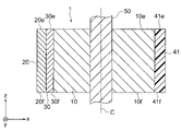
- one end face 41e in the axial direction of the resin portion 41 is one end face 10e in the axial direction of the first rotor core 10 and one in the axial direction of the second rotor core 20. It is flush with the end face 20e and one end face 30e in the axial direction of the permanent magnet 30.
- the other end surface 41f in the axial direction of the resin portion 41 is the other end surface 10f in the axial direction of the first rotor core 10, the other end surface 20f in the axial direction of the second rotor core 20, and the permanent magnet 30. Is flush with the other end face 30f in the axial direction of.
- the resin portion 41 may be integrally formed with another resin portion provided in the rotor 1.
- the resin portion 41 may be connected to another resin portion embedded between the shaft 50 and the first rotor core 10.
- the resin portion 41 is arranged so as to cover the end faces of the first rotor core 10, the second rotor core 20, and the permanent magnet 30 in the axial direction. It may be integrally formed with another resin portion (second resin portions 442 and 443 in FIG. 11).
- the stator 5 has a stator core 60.
- the stator core 60 has a plurality of electrical steel sheets (not shown) laminated in the z-axis direction.
- the plate thickness of the electromagnetic steel sheet used for the stator core 60 is the same as the plate thickness of the electromagnetic steel sheet used for the first rotor core 10 and the second rotor core 20.
- the plurality of electrical steel sheets laminated in the z-axis direction two electrical steel sheets adjacent to each other in the z-axis direction are fixed by caulking or the like.
- the stator core 60 is fixed to the frame 7. If the thickness of the electromagnetic steel sheet used for the stator core 60 is a predetermined thickness within the range of 0.1 mm to 0.7 mm, the first rotor core 10 and the second rotor core 20 are 20. It may be different from the plate thickness of the electromagnetic steel sheet 15 used in.
- the stator core 60 has a yoke portion 61, a plurality of teeth portions 62, and a plurality of slot portions 63.
- the yoke portion 61 extends in the circumferential direction R.
- the plurality of tooth portions 62 are arranged at equal intervals in the circumferential direction R.
- a coil 64 is wound around each of the teeth portions 62 of the plurality of teeth portions 62.
- the number of the plurality of teeth portions 62 is an arbitrary number of two or more.
- the slot portion 63 is a space formed between two teeth portions 62 adjacent to the circumferential direction R of the plurality of teeth portions 62.
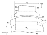
- FIG. 4 is an enlarged plan view showing the configuration around the teeth portion 62 of the electric motor 100 according to the first embodiment.
- the teeth portion 62 has a teeth extending portion 62a and a teeth tip portion 62b.
- the tooth extending portion 62a extends radially inward from the inner peripheral surface 61a of the yoke portion 61.
- the tooth tip portion 62b is arranged radially inside the tooth extending portion 62a.
- the teeth tip portion 62b is a portion of the teeth portion 62 that is wider in the circumferential direction than the teeth extending portion 62a.
- the length W 1 is It is smaller than the length W2.
- the length W 1 may be the length W 2 or less, and the length W 1 may be the same as the length W 2 . That is, the length W 1 and the length W 2 may satisfy the following equation (2). W 1 ⁇ W 2 (2)
- the stator core 60 further has a coil 64 and an insulating portion 65 arranged in the slot portion 63.
- the coil 64 is, for example, a magnet wire.
- the winding method of the coil 64 is, for example, a centralized winding in which the coil 64 is directly wound around the teeth portion 62 via the insulating portion 65.
- the number of turns and the wire diameter of the coil 64 are determined based on the characteristics (rotational speed, torque, etc.) required for the motor 100, the voltage specifications, and the cross-sectional area of the slot portion 63.
- a rotating magnetic field that rotates the rotor 1 is generated by energizing the coil 64 with a current having a frequency synchronized with the command rotation speed.
- the insulating portion 65 is, for example, an insulating film.
- FIG. 5 is a flowchart showing a manufacturing process of the rotor 1.
- the method for manufacturing the rotor 1 described below is an example, and other manufacturing methods may be used.
- step ST1 a first structure having a first rotor core 10, a plurality of second rotor cores 20, and a plurality of permanent magnets 30, that is, an intermediate structure shown in FIG. 6 (C) described later. 80 is formed.
- the intermediate structure 80 is a structure formed in the middle of the manufacturing process of the rotor 1. The details of the manufacturing process for forming the intermediate structure 80 will be described later.
- the resin portion 41 is formed by filling the resin between the adjacent second rotor cores 20 among the plurality of second rotor cores 20.
- the resin is formed between the two adjacent second rotor cores 20. Will be filled. This makes it possible to prevent a gap from being generated between the permanent magnet 30 and the first rotor core 10 and between the permanent magnet 30 and the second rotor core 20.
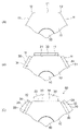
- FIGS. 6A to 6C are schematic views showing a manufacturing process of the intermediate structure 80.
- a molding die which is a die for forming the resin portion 41 shown in FIG. 2, is used.
- the process order of the intermediate structure 80 is not limited to the order shown in FIGS. 6 (A), (B) and (C), and may be any other order.
- the first rotor core 10 to which the shaft 50 is connected is arranged in the molding die.
- each permanent magnet 30 of the plurality of permanent magnets 30 is formed on the radial outward surface 11 of the first rotor core 10 arranged in the molding die. 31 is brought into contact with each other.
- the first surface 31 of the permanent magnet 30 abuts on the radial outward surface 11 of the first rotor core 10, and the second surface of the permanent magnet 30. 32 is in contact with the radial inward surface 22 of the second rotor core 20.
- no gap is generated between the permanent magnet 30 and the first rotor core 10 and between the permanent magnet 30 and the second rotor core 20. Therefore, it is possible to prevent the amount of the interlinkage magnetic flux from being reduced.
- the resin portion 41 fills the space between the two second rotor cores 20 adjacent to the circumferential direction R of the plurality of second rotor cores 20.
- the plurality of second rotor cores 20 are fixed to the first rotor core 10.
- the magnetic resistance between the two second rotor cores 20 is increased by filling the space between the two second rotor cores 20 adjacent to the circumferential direction R, the magnetic resistance between the two second rotor cores 20 increases. Leakage magnetic flux between two adjacent magnetic poles is suppressed.
- the first surface 31 of the permanent magnet 30 and the radial outward surface 11 of the first rotor core 10 are parallel to each other, and the second surface 32 of the permanent magnet 30 is formed. And the radial inward surfaces 22 of the second rotor core 20 are parallel to each other. This makes it possible to prevent a gap from being generated between the permanent magnet 30 and the first rotor core 10 and between the permanent magnet 30 and the second rotor core 20.
- the first surface 31 of the permanent magnet 30 and the radial outward surface 11 of the first rotor core 10 are flat surfaces
- the radial inward surface 22 of the second rotor core 20 is a flat surface.
- the permanent magnet 30 is a rectangular parallelepiped.
- the permanent magnet 30 abuts on the radial inward surface 22 of the first rotor core 20 and the first surface 31 that abuts on the radial outward surface 11 of the first rotor core 10.
- the second surface 32 is a flat surface. Therefore, the simple shape can prevent a gap from being generated between the permanent magnet 30 and the first rotor core 10 and between the permanent magnet 30 and the second rotor core 20. Further, since the permanent magnet 30 is a rectangular parallelepiped, the structure of the mold for molding the permanent magnet 30 can be simplified.
- the permanent magnet 30 is a sintered magnet. Since the magnetic force of the sintered magnet is larger than the magnetic force of the bonded magnet, the amount of magnetic flux of the interlinkage magnetic flux can be increased. Here, the dimensional accuracy of the sintered magnet is worse than the dimensional accuracy of the bonded magnet.
- the first surface 31 of the permanent magnet 30 abuts on the radial outward surface 11 of the first rotor core 10, and the second surface of the permanent magnet 30 is in contact with the surface 11.
- the radial inward surface 22 of the second rotor core 20 abuts on 32.
- the permanent magnet 30 is a sintered magnet, no gap is generated between the permanent magnet 30 and the rotor core (that is, the first rotor core 10 and the second rotor core 20). It is possible to prevent a decrease in the amount of the interlinkage magnetic flux.
- the permanent magnet 30 is a neodymium rare earth magnet.
- the magnetic force of the rotor 1 can be increased.
- neodymium rare earth magnets are more likely to react with oxygen than other magnets, and therefore are more likely to rust.
- the permanent magnet 30 since no gap is generated between the permanent magnet 30 and the first rotor core 10 and between the permanent magnet 30 and the second rotor core 20, the permanent magnet 30 is oxygenated. It is hard to react with. Therefore, even if the permanent magnet 30 is a neodymium rare earth magnet, the permanent magnet 30 can be made hard to rust.
- the angle ⁇ indicating the angle range about the axis C of the resin portion 41 existing between the two magnetic poles P adjacent to the circumferential direction R is the teeth portion of the stator core 60.
- the above-mentioned equation (1) represented by the number T of 62 and the number N of the magnetic poles P of the rotor 1 is satisfied.
- the length of the peripheral direction R of the permanent magnet 30 is sufficiently secured while firmly fixing the plurality of second rotor cores 20 and the plurality of permanent magnets 30 to the first rotor core 10.
- the magnetic force of the rotor 1 can be sufficiently secured.
- FIG. 7 is a plan view showing the configuration of the rotor 1a according to the first modification of the first embodiment.
- components that are the same as or correspond to the components shown in FIG. 2 are designated by the same reference numerals as those shown in FIG.
- the rotor 1a according to the first modification of the first embodiment relates to the first embodiment in terms of the shape of the first rotor core 10a, the shape of the second rotor core 20a, and the arrangement of the permanent magnets 30a. It is different from the rotor 1. Except for these points, the first modification of the first embodiment is the same as that of the first embodiment. Therefore, in the following description, FIG. 1 will be referred to.
- the rotor 1a includes a first rotor core 10a, a plurality of second rotor cores 20a, a plurality of permanent magnets 30a, a resin portion 41, and a shaft 50. is doing.
- the first rotor core 10a has a surface 11a facing outward in the radial direction.
- the central portion of the radial outward facing surface 11a in the circumferential direction R is located radially inward from the end portion of the surface 11a in the circumferential direction R.
- the second rotor core 20a has a radial inward surface 22a.
- the central portion of the radial inward facing surface 22a in the circumferential direction R is located radially inward from the end portion of the surface 22a in the circumferential direction R.
- Two permanent magnets 30a are arranged between the radial outward surface 11a of the first rotor core 10a and the radial inward surface 22a of the second rotor core 20a. As a result, the magnetic force of the rotor 1a according to the first modification of the first embodiment can be made larger than the magnetic force of the rotor 1 according to the first embodiment.
- the two permanent magnets 30a are arranged so as to form a convex V shape inward in the radial direction.
- the permanent magnet 30a has a first surface 31a and a second surface 32a.
- the first surface 31a is in contact with the radial outward surface 11a of the first rotor core 10a.
- the second surface 32a is in contact with the radial inward surface 22a of the second rotor core 20a.
- the rotor 1a has two permanent magnets 30a between the radial outward surface 11a of the first rotor core 10a and the radial inward surface 22a of the second rotor core 20a. Have been placed.
- the magnetic force of the rotor 1a according to the first modification of the first embodiment can be made larger than the magnetic force of the rotor 1 according to the first embodiment.
- FIG. 8 is a plan view showing the configuration of the rotor 1b according to the second modification of the first embodiment.
- components that are the same as or correspond to the components shown in FIG. 2 are designated by the same reference numerals as those shown in FIG.
- the rotor 1b according to the second modification of the first embodiment is the same as the first embodiment in terms of the shape of the first rotor core 10b, the shape of the second rotor core 20b, and the shape of the permanent magnet 30b. It is different from the rotor 1. Except for these points, the second modification of the first embodiment is the same as that of the first embodiment. Therefore, in the following description, FIG. 1 will be referred to.
- the rotor 1b includes a first rotor core 10b, a plurality of second rotor cores 20b, a plurality of permanent magnets 30b, a resin portion 41, and a shaft 50. is doing.
- the first surface 31b of the permanent magnet 30b is in contact with the radial outward surface 11b of the first rotor core 10b.
- the first surface 31b of the permanent magnet 30b and the first radial outward surface 11b of the first rotor core 10b are curved surfaces having the same shape and are in close contact with each other.
- the second surface 32b is in contact with the radial inward surface 22b of the second rotor core 20b.
- the second surface 32b of the permanent magnet 30b and the radially inward surface 22b of the second rotor core 20b are curved surfaces having the same shape and are in close contact with each other.
- the first surface 31b of the permanent magnet 30b is a semi-cylindrical convex surface as the first convex surface
- the radial outward surface 11b of the first rotor core 10b is the first concave surface. It is a semi-cylindrical concave surface as.
- the second surface 32b of the permanent magnet 30b is a semi-cylindrical concave surface as a second concave surface
- the radial inward surface 22b of the second rotor core 20b is a semicircle as a second convex surface. It is a columnar convex surface.
- the length of the circumferential direction R of the permanent magnet 30b is the permanent magnet of the first embodiment. It is longer than the length of the circumferential direction R of 30. Therefore, the magnetic force of the rotor 1b according to the second modification of the first embodiment can be made larger than the magnetic force of the rotor 1 according to the first embodiment.
- both the first surface 31b and the second surface 32b of the permanent magnet 30b are curved surfaces.
- the length of the permanent magnet 30b in the circumferential direction R becomes longer than the length of the permanent magnet 30 of the first embodiment in the circumferential direction R. Therefore, the magnetic force of the rotor 1b according to the second modification of the first embodiment can be made larger than the magnetic force of the rotor 1 according to the first embodiment.
- FIG. 9 is a plan view showing the configuration of the rotor 2 according to the second embodiment.
- components that are the same as or correspond to the components shown in FIG. 2 are designated by the same reference numerals as those shown in FIG.
- the rotor 2 according to the second embodiment is different from the rotor 1 according to the first embodiment in the shape of the second rotor core 220. Except for these points, the second embodiment is the same as the first embodiment. Therefore, in the following description, FIG. 2 will be referred to.
- the rotor 2 has a first rotor core 10, a plurality of second rotor cores 220, a plurality of permanent magnets 30, and a resin portion 241.
- the second rotor core 220 includes a plurality of side surfaces 223 connecting a radial outward surface 21, a radial inward surface 22, and a radial outward surface 21 and a radial inward surface 22. Have.
- L is a straight line extending in a direction orthogonal to the magnetic pole center line M and orthogonal to the shaft 50. Further, when the angle formed by the straight line L and the side surface 223 on the magnetic pole center line M side is ⁇ , the angle ⁇ satisfies the following equation (2). ⁇ ⁇ 90 ° (2)
- the amount of the resin portion 241 filling the space between the two second rotor cores 220 adjacent to the circumferential direction R is larger than the amount of the resin portion 41 of the first embodiment. ..
- the resin portion 241 is also arranged radially outside the edge 22s of the circumferential direction R on the surface 22 facing inward in the radial direction. Further has. As a result, the resin portion 241 can more firmly fix the second rotor core 20 to the first rotor core 10. Therefore, it is possible to prevent the second rotor core 20 from being displaced outward in the radial direction due to the centrifugal force during the rotation of the electric motor 100.
- the angle ⁇ on the magnetic pole center line M side among the angles formed by the straight line L extending in the direction orthogonal to the magnetic pole center line M and orthogonal to the shaft 50 and the side surface 223 is 90. Less than degree.
- the resin portion 241 can more firmly fix the second rotor core 20 to the first rotor core 10. Therefore, it is possible to prevent the second rotor core 20 from being displaced outward in the radial direction due to the centrifugal force during the rotation of the electric motor 100.
- FIG. 10 is a plan view showing the configuration of the rotor 3 according to the third embodiment.
- components that are the same as or correspond to the components shown in FIG. 1 are designated by the same reference numerals as those shown in FIG.
- the rotor 3 according to the third embodiment is different from the rotor 1 according to the first embodiment in the configuration of the first rotor core 310.
- the rotor 3 according to the third embodiment is the same as the rotor 1 according to the first embodiment. Therefore, in the following description, FIG. 1 will be referred to.
- the rotor 3 includes a first rotor core 310, a plurality of second rotor cores 20, a plurality of permanent magnets 30, and a resin portion 41. have.
- the first rotor core 310 has a plurality of split core portions 370 arranged in the circumferential direction R.
- the first rotor core 310 is divided at the protrusion 12. That is, the first rotor core 310 is divided at a portion between two permanent magnets 30 adjacent to each other in the circumferential direction R. Therefore, in the third embodiment, the number of the plurality of divided iron core portions 370 corresponds to the number of magnetic poles of the rotor 3 (that is, the number of permanent magnets 30). Specifically, the number of the plurality of divided iron core portions 370 is the same as the number of magnetic poles of the rotor 3.
- Each of the divided core portions 370 among the plurality of divided core portions 370 has a surface 311 facing outward in the radial direction.
- the first surface 31 of the permanent magnet 30 is in contact with the radial outward surface 311 of the split iron core portion 370.
- no gap is generated between the permanent magnet 30 and the split iron core portion 370. Therefore, it is possible to prevent the amount of the interlinkage magnetic flux from being reduced.
- the plurality of divided iron core portions 370 have a plurality of electromagnetic steel sheets laminated in the z-axis direction.
- the machined area at the time of punching of the electrical steel sheet at the time of manufacturing the first rotor core 310 is the same as the flat area of the divided core portion 370 when viewed in the z-axis direction.
- the processed area of the electrical steel sheet 15 at the time of punching is the same as the flat area of the annular first rotor core 10. Therefore, in the third embodiment, the machined area of the electrical steel sheet 15 at the time of punching is narrower than the area of the electrical steel sheet 15 at the time of punching in the first embodiment. Therefore, in the third embodiment, the yield at the time of manufacturing the first rotor core 310 can be improved.
- the first surface 31 of the permanent magnet 30 abuts on the radial outward surface 311 of the first rotor core 310, and the second surface of the permanent magnet 30. 32 is in contact with the radial inward surface 22a of the second rotor core 20a.
- no gap is generated between the permanent magnet 30 and the first rotor core 310, and between the permanent magnet 30 and the second rotor core 20. Therefore, it is possible to prevent the amount of the interlinkage magnetic flux from being reduced.
- the first rotor core 310 has a plurality of split core portions 370. Thereby, the yield at the time of manufacturing the first rotor core 310 can be improved.
- FIG. 11 is a plan view showing the configuration of the rotor 3a according to the first modification of the third embodiment.
- components that are the same as or correspond to the components shown in FIG. 10 are designated by the same reference numerals as those shown in FIG.
- the rotor 3a according to the first modification of the third embodiment is different from the rotor 3 according to the third embodiment in the shape of the first rotor core 310a.
- the first rotor core 310a has a plurality of split core portions 370a arranged in the circumferential direction R.
- Each of the divided core portions 370a of the plurality of divided core portions 370a is fitted to the convex portion 371 as the first fitting portion and the convex portion 371 of the other divided core portions 370a adjacent to the circumferential direction R. It has a recess 372 as a fitting portion.
- the two adjacent split core portions 370a are firmly fixed. To. Therefore, the rigidity of the first rotor core 310a can be improved.
- one of the two adjacent split core portions 370a of the plurality of split core portions 370a has the convex portion 371, and the other of the two split core portions 370a.
- the two adjacent split iron core portions 370a are firmly fixed. Therefore, the rigidity of the first rotor core 310a can be improved.
- FIG. 12 is a cross-sectional view showing the configuration of the rotor 4 according to the fourth embodiment.
- the rotor 4 according to the fourth embodiment further includes second resin portions 442 and 443 that cover the axial end faces of the first rotor core 10, the second rotor core 20, and the permanent magnet 30, respectively. This is different from the rotor 1 according to the first embodiment.
- the rotor 4 according to the fourth embodiment is the same as the rotor 1 according to the first embodiment. Therefore, in the following description, FIG. 2 will be referred to.
- the rotor 4 includes a first rotor core 10, a plurality of second rotor cores 20, a plurality of permanent magnets 30, a first resin portion 441, and a shaft 50. And a plurality of second resin portions 442 and 443.
- the first resin portion 441 fills the space between the two second rotor cores 20 (see FIG. 2) adjacent to the circumferential direction R of the plurality of second rotor cores 20.
- the second resin portion 442 is arranged so as to cover one end face 10e, 20e, 30e in the axial direction of the first rotor core 10, the second rotor core 20, and the permanent magnet 30, respectively.
- the second resin portion 443 is arranged so as to cover the other end faces 10f, 20f, and 30f in the axial direction of the first rotor core 10, the second rotor core 20, and the permanent magnet 30, respectively.
- the second resin portions 442 and 443 cover the axial end faces 30e and 30f of the permanent magnet 30, so that the permanent magnet 30 is not exposed to air. The generation of rust in the permanent magnet 30 can be suppressed, and the good magnetic characteristics of the permanent magnet 30 can be maintained.
- the second resin portions 442 and 443 and the first resin portion 441 are integrally formed.
- the plurality of first resin portions 441 arranged in the circumferential direction R are connected to each other via the second resin portions 442 and 443, so that the rigidity of the rotor 4 can be improved.
- the rotor 4 can be realized even if the second resin portions 442 and 443 are not integrally formed with the first resin portion 441. Further, the rotor 4 may have only the second resin portion of any one of the plurality of second resin portions 442 and 443.
- the rotor 4 covers the axial end faces of the first rotor core 10, the second rotor core 20, and the permanent magnet 30 in the axial direction. It further has second resin portions 442 and 443 arranged in. Thereby, the plurality of second rotor cores 20 and the plurality of permanent magnets 30 can be more firmly fixed to the first rotor core 10.
- the second resin portions 442 and 443 cover the axial end faces 30e and 30f of the permanent magnet 30, respectively.
- the permanent magnet 30 is not exposed to the air. Therefore, the generation of rust in the permanent magnet 30 can be suppressed, and the good magnetic characteristics of the permanent magnet 30 can be maintained.
- the second resin portion 442 is connected to the first resin portion 441.
- the plurality of first resin portions 441 arranged in the circumferential direction R are connected to each other via the second resin portions 442 and 443, so that the rigidity of the rotor 4 can be improved.
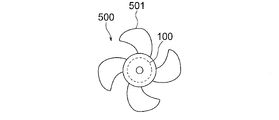
- FIG. 13 is a diagram showing the configuration of the blower 500 according to the fifth embodiment.
- the blower 500 has an electric motor 100 and a fan 501 driven by the electric motor 100.
- the fan 501 is attached to the shaft of the motor 100.
- the fan 501 rotates and an air flow is generated.
- the blower 500 is used, for example, as an outdoor blower for the outdoor unit 620 of the air conditioner 600 shown in FIG. 14 described later.
- the fan 501 is, for example, a propeller fan.
- the blower 500 has the electric motor 100 described in the first embodiment. As described above, in the electric motor 100 according to the first embodiment, it is possible to prevent a decrease in the magnetic flux amount of the interlinkage magnetic flux, so that it is possible to prevent a decrease in the output torque of the electric motor 100. Therefore, it is possible to prevent the output of the blower 500 from decreasing.
- FIG. 14 is a diagram showing the configuration of the air conditioner 600 according to the sixth embodiment.
- the air conditioner 600 has an indoor unit 610, an outdoor unit 620, and a refrigerant pipe 630.
- the indoor unit 610 and the outdoor unit 620 are connected by a refrigerant pipe 630 to form a refrigerant circuit in which the refrigerant circulates.
- the air conditioner 600 can perform an operation such as a cooling operation in which cold air is blown from the indoor unit 610 or a heating operation in which warm air is blown from the indoor unit 610.
- the indoor unit 610 has an indoor blower 611 and a housing 612 for accommodating the indoor blower 611.
- the indoor blower 611 has an electric motor 611a and a fan 611b driven by the electric motor 611a.
- the fan 611b is attached to the shaft of the motor 611a. When the shaft of the electric motor 611a rotates, the fan 611b rotates and an air flow is generated.
- the fan 611b is, for example, a cross-flow fan.
- the outdoor unit 620 has a blower 500 as an outdoor blower, a compressor 621, and a housing 622 for accommodating the blower 500 and the compressor 621.
- the compressor 621 has a compression mechanism unit 621a for compressing the refrigerant and an electric motor 621b for driving the compression mechanism unit 621a.
- the compression mechanism portion 621a and the electric motor 621b are connected to each other by a rotating shaft 621c.
- the electric motor 621b of the compressor 621 the electric motor 100 according to the first embodiment may be used.
- the heat released when the refrigerant compressed by the compressor 621 is condensed by the condenser (not shown) is released to the outside by the blower of the blower 500.
- the blower 500 according to the fifth embodiment is not limited to the outdoor blower of the outdoor unit 620, and may be used as the above-mentioned indoor blower 611. Further, the blower 500 is not limited to the air conditioner 600, and may be provided in other devices.
- the outdoor unit 620 further has a four-way valve (not shown) for switching the flow direction of the refrigerant.
- the four-way valve of the outdoor unit 620 causes the high-temperature and high-pressure refrigerant gas sent out from the compressor 621 to flow through the heat exchanger of the outdoor unit 620 during the cooling operation and through the heat exchanger of the indoor unit 610 during the heating operation.
- the air conditioner 600 has a blower 500.
- the blower 500 since the blower 500 has the electric motor 100 described in the first embodiment, it is possible to prevent the output of the blower 500 from decreasing. Therefore, it is possible to prevent the output of the air conditioner 600 from decreasing.
Landscapes
- Engineering & Computer Science (AREA)
- Power Engineering (AREA)
- Mechanical Engineering (AREA)
- General Engineering & Computer Science (AREA)
- Manufacturing & Machinery (AREA)
- Chemical & Material Sciences (AREA)
- Combustion & Propulsion (AREA)
- Physics & Mathematics (AREA)
- Thermal Sciences (AREA)
- Permanent Field Magnets Of Synchronous Machinery (AREA)
- Iron Core Of Rotating Electric Machines (AREA)
Priority Applications (4)
| Application Number | Priority Date | Filing Date | Title |
|---|---|---|---|
| US18/027,479 US20230378829A1 (en) | 2020-11-19 | 2020-11-19 | Rotor, motor, blower, air conditioner, and manufacturing method of rotor |
| JP2022563329A JP7403685B2 (ja) | 2020-11-19 | 2020-11-19 | 回転子、電動機、送風機、空気調和装置、及び回転子の製造方法 |
| CN202080107040.XA CN116458034A (zh) | 2020-11-19 | 2020-11-19 | 转子、电动机、送风机、空调装置以及转子的制造方法 |
| PCT/JP2020/043191 WO2022107273A1 (ja) | 2020-11-19 | 2020-11-19 | 回転子、電動機、送風機、空気調和装置、及び回転子の製造方法 |
Applications Claiming Priority (1)
| Application Number | Priority Date | Filing Date | Title |
|---|---|---|---|
| PCT/JP2020/043191 WO2022107273A1 (ja) | 2020-11-19 | 2020-11-19 | 回転子、電動機、送風機、空気調和装置、及び回転子の製造方法 |
Publications (1)
| Publication Number | Publication Date |
|---|---|
| WO2022107273A1 true WO2022107273A1 (ja) | 2022-05-27 |
Family
ID=81708591
Family Applications (1)
| Application Number | Title | Priority Date | Filing Date |
|---|---|---|---|
| PCT/JP2020/043191 Ceased WO2022107273A1 (ja) | 2020-11-19 | 2020-11-19 | 回転子、電動機、送風機、空気調和装置、及び回転子の製造方法 |
Country Status (4)
| Country | Link |
|---|---|
| US (1) | US20230378829A1 (https=) |
| JP (1) | JP7403685B2 (https=) |
| CN (1) | CN116458034A (https=) |
| WO (1) | WO2022107273A1 (https=) |
Citations (9)
| Publication number | Priority date | Publication date | Assignee | Title |
|---|---|---|---|---|
| US4393320A (en) * | 1981-09-02 | 1983-07-12 | Carrier Corporation | Permanent magnet rotor |
| JP2002354729A (ja) * | 2001-05-25 | 2002-12-06 | Hitachi Ltd | 永久磁石式回転電機およびそれを用いた空気調和機 |
| JP2007060860A (ja) * | 2005-08-26 | 2007-03-08 | Honda Motor Co Ltd | 永久磁石式回転子 |
| JP2013524757A (ja) * | 2010-03-30 | 2013-06-17 | ボルボ テクノロジー コーポレイション | 埋込型永久磁石を備えた電気機械の回転子及び電気機械 |
| JP2016111787A (ja) * | 2014-12-04 | 2016-06-20 | 株式会社ジェイテクト | 埋込磁石型ロータ、および埋込磁石型ロータの製造方法 |
| WO2018043026A1 (ja) * | 2016-08-29 | 2018-03-08 | パナソニックIpマネジメント株式会社 | 表面磁石型モータ |
| WO2018180692A1 (ja) * | 2017-03-30 | 2018-10-04 | 日本電産株式会社 | ロータ、及びモータ |
| WO2020183523A1 (ja) * | 2019-03-08 | 2020-09-17 | 三菱電機株式会社 | モータ、ファン、および空気調和機 |
| JP2020156295A (ja) * | 2019-03-22 | 2020-09-24 | 株式会社デンソー | 回転電機の回転子及びその製造方法 |
Family Cites Families (19)
| Publication number | Priority date | Publication date | Assignee | Title |
|---|---|---|---|---|
| JP3752946B2 (ja) | 2000-02-24 | 2006-03-08 | いすゞ自動車株式会社 | 回転機のロータの製作方法 |
| JP2002171702A (ja) | 2000-12-05 | 2002-06-14 | Isuzu Motors Ltd | 回転機のロータ |
| JP4719183B2 (ja) | 2007-05-31 | 2011-07-06 | トヨタ自動車株式会社 | 回転電機 |
| JP5521820B2 (ja) | 2009-09-07 | 2014-06-18 | 株式会社安川電機 | 回転電機およびその製造方法 |
| DE102011107803B4 (de) * | 2010-07-21 | 2025-02-27 | Denso Corporation | Motor |
| JP2012165576A (ja) | 2011-02-08 | 2012-08-30 | Yaskawa Electric Corp | 回転電機および回転電機の製造方法 |
| JP2013176210A (ja) | 2012-02-24 | 2013-09-05 | Toyota Motor Corp | 回転電機用ロータ及びその製造方法 |
| JP2017005854A (ja) * | 2015-06-10 | 2017-01-05 | 日本電産テクノモータ株式会社 | ロータ、モータ、およびロータの製造方法 |
| JP6629133B2 (ja) * | 2016-04-26 | 2020-01-15 | 日立オートモティブシステムズエンジニアリング株式会社 | 電動機 |
| CN109417321A (zh) * | 2016-07-15 | 2019-03-01 | 三菱电机株式会社 | 交替极型转子、电动机、空调机以及交替极型转子的制造方法 |
| WO2018062447A1 (ja) * | 2016-09-30 | 2018-04-05 | 日本電産株式会社 | ロータ、及びモータ |
| CN110622394B (zh) * | 2017-05-25 | 2022-01-11 | 三菱电机株式会社 | 定子、电动机、压缩机及空调装置 |
| WO2019016893A1 (ja) * | 2017-07-19 | 2019-01-24 | 三菱電機株式会社 | 回転電機 |
| ES2948863T3 (es) * | 2018-03-12 | 2023-09-20 | Mitsubishi Electric Corp | Motor eléctrico, compresor, ventilador y aparato de refrigeración y aire acondicionado |
| DE112019001628T5 (de) * | 2018-03-27 | 2020-12-10 | Denso Corporation | Motor |
| WO2019189313A1 (ja) * | 2018-03-30 | 2019-10-03 | 日本電産株式会社 | ロータ、モータおよび電動パワーステアリング装置 |
| CN111903040B (zh) * | 2018-03-30 | 2022-11-25 | 日本电产株式会社 | 转子、马达以及电动助力转向装置 |
| WO2020208924A1 (ja) * | 2019-04-11 | 2020-10-15 | 三菱電機株式会社 | 永久磁石型回転電機および永久磁石型回転電機の製造方法 |
| JP7363296B2 (ja) * | 2019-09-30 | 2023-10-18 | ニデック株式会社 | ホルダ、ロータ、モータ、およびロータの製造方法 |
-
2020
- 2020-11-19 US US18/027,479 patent/US20230378829A1/en not_active Abandoned
- 2020-11-19 CN CN202080107040.XA patent/CN116458034A/zh active Pending
- 2020-11-19 WO PCT/JP2020/043191 patent/WO2022107273A1/ja not_active Ceased
- 2020-11-19 JP JP2022563329A patent/JP7403685B2/ja active Active
Patent Citations (9)
| Publication number | Priority date | Publication date | Assignee | Title |
|---|---|---|---|---|
| US4393320A (en) * | 1981-09-02 | 1983-07-12 | Carrier Corporation | Permanent magnet rotor |
| JP2002354729A (ja) * | 2001-05-25 | 2002-12-06 | Hitachi Ltd | 永久磁石式回転電機およびそれを用いた空気調和機 |
| JP2007060860A (ja) * | 2005-08-26 | 2007-03-08 | Honda Motor Co Ltd | 永久磁石式回転子 |
| JP2013524757A (ja) * | 2010-03-30 | 2013-06-17 | ボルボ テクノロジー コーポレイション | 埋込型永久磁石を備えた電気機械の回転子及び電気機械 |
| JP2016111787A (ja) * | 2014-12-04 | 2016-06-20 | 株式会社ジェイテクト | 埋込磁石型ロータ、および埋込磁石型ロータの製造方法 |
| WO2018043026A1 (ja) * | 2016-08-29 | 2018-03-08 | パナソニックIpマネジメント株式会社 | 表面磁石型モータ |
| WO2018180692A1 (ja) * | 2017-03-30 | 2018-10-04 | 日本電産株式会社 | ロータ、及びモータ |
| WO2020183523A1 (ja) * | 2019-03-08 | 2020-09-17 | 三菱電機株式会社 | モータ、ファン、および空気調和機 |
| JP2020156295A (ja) * | 2019-03-22 | 2020-09-24 | 株式会社デンソー | 回転電機の回転子及びその製造方法 |
Also Published As
| Publication number | Publication date |
|---|---|
| US20230378829A1 (en) | 2023-11-23 |
| JP7403685B2 (ja) | 2023-12-22 |
| JPWO2022107273A1 (https=) | 2022-05-27 |
| CN116458034A (zh) | 2023-07-18 |
Similar Documents
| Publication | Publication Date | Title |
|---|---|---|
| US9318927B2 (en) | Amorphous stator, and electric motor using same | |
| US10931155B2 (en) | Rotor, electric motor, compressor, air conditioner, and method for manufacturing electric motor | |
| EP2372871A2 (en) | Permanent magnet motor | |
| WO2018189881A1 (ja) | ロータ、電動機および空気調和装置 | |
| JP7486629B2 (ja) | 回転子、電動機、送風機、空気調和装置、及び回転子の製造方法 | |
| JP7150181B2 (ja) | モータ、圧縮機、及び空気調和機 | |
| WO2018029818A1 (ja) | 電動機、圧縮機、冷凍空調装置および電動機の製造方法 | |
| WO2018066084A1 (ja) | 電動機および空気調和装置 | |
| WO2019073509A1 (ja) | 固定子、電動機、圧縮機、空気調和装置および固定子の製造方法 | |
| WO2020129123A1 (ja) | 回転子、電動機、送風機、及び空気調和機、並びに回転子の製造方法 | |
| US20250211043A1 (en) | Motor, blower, and air conditioner | |
| JPWO2018016026A1 (ja) | モータ及び空気調和機 | |
| JP7442688B2 (ja) | 回転子、電動機、送風機及び空気調和装置 | |
| US11462956B2 (en) | Electric motor, compressor, air conditioner, and manufacturing method of electric motor | |
| US12009698B2 (en) | Rotor, electric motor, fan, and air conditioner | |
| JP7403685B2 (ja) | 回転子、電動機、送風機、空気調和装置、及び回転子の製造方法 | |
| JP7098047B2 (ja) | モータ、ファン、および空気調和機 | |
| WO2018011850A1 (ja) | ロータ、電動機、送風機、圧縮機および空気調和装置 | |
| JP7559044B2 (ja) | 電動機、ファン、及び空気調和機 | |
| JP2023076591A (ja) | コンシクエントポール型ロータ、電動機、ファン、及び空気調和機 | |
| JP7063916B2 (ja) | ロータ、電動機、圧縮機、空気調和機、及びロータの製造方法 | |
| CN115298929A (zh) | 转子、电动机、压缩机、制冷循环装置及空气调节装置 | |
| US20250038594A1 (en) | Rotor, electric motor, blower, and air conditioner | |
| JPWO2020044420A1 (ja) | ステータ、モータ、ファン、及び空気調和機並びにステータの製造方法 | |
| JP2025060197A (ja) | 回転電機、圧縮機、送風機、冷凍機 |
Legal Events
| Date | Code | Title | Description |
|---|---|---|---|
| 121 | Ep: the epo has been informed by wipo that ep was designated in this application |
Ref document number: 20962437 Country of ref document: EP Kind code of ref document: A1 |
|
| ENP | Entry into the national phase |
Ref document number: 2022563329 Country of ref document: JP Kind code of ref document: A |
|
| WWE | Wipo information: entry into national phase |
Ref document number: 202080107040.X Country of ref document: CN |
|
| NENP | Non-entry into the national phase |
Ref country code: DE |
|
| 122 | Ep: pct application non-entry in european phase |
Ref document number: 20962437 Country of ref document: EP Kind code of ref document: A1 |