WO2022102667A1 - 蒸発加湿器 - Google Patents
蒸発加湿器 Download PDFInfo
- Publication number
- WO2022102667A1 WO2022102667A1 PCT/JP2021/041388 JP2021041388W WO2022102667A1 WO 2022102667 A1 WO2022102667 A1 WO 2022102667A1 JP 2021041388 W JP2021041388 W JP 2021041388W WO 2022102667 A1 WO2022102667 A1 WO 2022102667A1
- Authority
- WO
- WIPO (PCT)
- Prior art keywords
- water
- temperature
- storage
- evaporation humidifier
- tank
- Prior art date
- Legal status (The legal status is an assumption and is not a legal conclusion. Google has not performed a legal analysis and makes no representation as to the accuracy of the status listed.)
- Ceased
Links
Images


Classifications
-
- F—MECHANICAL ENGINEERING; LIGHTING; HEATING; WEAPONS; BLASTING
- F24—HEATING; RANGES; VENTILATING
- F24F—AIR-CONDITIONING; AIR-HUMIDIFICATION; VENTILATION; USE OF AIR CURRENTS FOR SCREENING
- F24F6/00—Air-humidification, e.g. cooling by humidification
- F24F6/02—Air-humidification, e.g. cooling by humidification by evaporation of water in the air
-
- F—MECHANICAL ENGINEERING; LIGHTING; HEATING; WEAPONS; BLASTING
- F24—HEATING; RANGES; VENTILATING
- F24F—AIR-CONDITIONING; AIR-HUMIDIFICATION; VENTILATION; USE OF AIR CURRENTS FOR SCREENING
- F24F6/00—Air-humidification, e.g. cooling by humidification
- F24F6/12—Air-humidification, e.g. cooling by humidification by forming water dispersions in the air
- F24F6/14—Air-humidification, e.g. cooling by humidification by forming water dispersions in the air using nozzles
-
- F—MECHANICAL ENGINEERING; LIGHTING; HEATING; WEAPONS; BLASTING
- F25—REFRIGERATION OR COOLING; COMBINED HEATING AND REFRIGERATION SYSTEMS; HEAT PUMP SYSTEMS; MANUFACTURE OR STORAGE OF ICE; LIQUEFACTION SOLIDIFICATION OF GASES
- F25D—REFRIGERATORS; COLD ROOMS; ICE-BOXES; COOLING OR FREEZING APPARATUS NOT OTHERWISE PROVIDED FOR
- F25D17/00—Arrangements for circulating cooling fluids; Arrangements for circulating gas, e.g. air, within refrigerated spaces
- F25D17/04—Arrangements for circulating cooling fluids; Arrangements for circulating gas, e.g. air, within refrigerated spaces for circulating air, e.g. by convection
- F25D17/042—Air treating means within refrigerated spaces
-
- F—MECHANICAL ENGINEERING; LIGHTING; HEATING; WEAPONS; BLASTING
- F24—HEATING; RANGES; VENTILATING
- F24F—AIR-CONDITIONING; AIR-HUMIDIFICATION; VENTILATION; USE OF AIR CURRENTS FOR SCREENING
- F24F6/00—Air-humidification, e.g. cooling by humidification
- F24F2006/008—Air-humidifier with water reservoir
-
- F—MECHANICAL ENGINEERING; LIGHTING; HEATING; WEAPONS; BLASTING
- F24—HEATING; RANGES; VENTILATING
- F24F—AIR-CONDITIONING; AIR-HUMIDIFICATION; VENTILATION; USE OF AIR CURRENTS FOR SCREENING
- F24F6/00—Air-humidification, e.g. cooling by humidification
- F24F6/12—Air-humidification, e.g. cooling by humidification by forming water dispersions in the air
- F24F6/14—Air-humidification, e.g. cooling by humidification by forming water dispersions in the air using nozzles
- F24F2006/143—Air-humidification, e.g. cooling by humidification by forming water dispersions in the air using nozzles using pressurised air for spraying
-
- F—MECHANICAL ENGINEERING; LIGHTING; HEATING; WEAPONS; BLASTING
- F25—REFRIGERATION OR COOLING; COMBINED HEATING AND REFRIGERATION SYSTEMS; HEAT PUMP SYSTEMS; MANUFACTURE OR STORAGE OF ICE; LIQUEFACTION SOLIDIFICATION OF GASES
- F25D—REFRIGERATORS; COLD ROOMS; ICE-BOXES; COOLING OR FREEZING APPARATUS NOT OTHERWISE PROVIDED FOR
- F25D2317/00—Details or arrangements for circulating cooling fluids; Details or arrangements for circulating gas, e.g. air, within refrigerated spaces, not provided for in other groups of this subclass
- F25D2317/04—Treating air flowing to refrigeration compartments
- F25D2317/041—Treating air flowing to refrigeration compartments by purification
- F25D2317/0413—Treating air flowing to refrigeration compartments by purification by humidification
Definitions
- a constant temperature and high humidity storage (hereinafter, may be referred to as "storage"). Is used. Generally, the lower the temperature of food, the easier it is to maintain its freshness. Therefore, the freshness of food is ensured by keeping the temperature in the constant temperature and high humidity storage at low temperature and high humidity.
- Moisture accounts for 70% to 80% of meat and seafood, and 80% to 90% or more of fruits and vegetables.
- the temperature of the storage is lowered and the food is cooled to below freezing point, the water freezes, the volume expands, and large ice crystals form in the extracellular fluid of the food. This destroys the cell membrane of the food and freezes the food in that state. After thawing, the drip will flow out.
- the inside of the refrigerator dries due to frosting on the evaporator, defrosting, and drainage of defrosted water to the outside during refrigeration. Drying impairs the quality of fruits and vegetables and / or flowers in particular. Even in the aging of livestock meat by refrigeration, drying causes deterioration of livestock meat quality.
- Patent Document 1 a cold temperature / humidity changing unit including an icebreaker heat exchanger is arranged between the first blower mechanism and the second blower mechanism adjacent to the first blower mechanism and the second blower mechanism.
- the evaporator for the storage is disclosed. Since this cold temperature / humidity changing part has ice supplied from the icebreaker part, the basic airflow comes into contact with the ice and becomes an airflow of 0 ° C.
- the humidifying device includes water spray humidification, ultrasonic water humidification, heater steam humidification, and humidification by blowing air to a water-containing material.
- the bubble humidifier is generally used for medical purposes for the purpose of supplying inhaled oxygen into water as bubbles during oxygen inhalation to humidify the discharged gas.
- Patent Document 2 describes an evaporator in which a bubble generator is provided in a water tank and humidified air generated from the water surface is supplied to an adjacent environmental test room by a duct.
- Patent Document 3 describes a humidifier that generates bubbles by turning the water in the water tank into hot water with a heating device, and mixes the humidified air generated from the water surface with the blower by the blower mechanism and supplies the humidifier to the outside. Has been done.
- the crushed ice below the freezing point produced by the ice maker is heated to 0 ° C. and the ice surface is covered with melted water.
- the surface melt water evaporates, steam at 0 ° C. is generated, and the air is blown into the storage.
- the evaporator described in Patent Document 1 has a temperature of 60 Hz in order to maintain a constant temperature and saturation humidity after the temperature reaches 0 ° C. and a relative humidity of 100%.
- a phase 100V, 493W ice maker consumes 60kg to 70kg of crushed ice a day.
- the icebreaker that passes through the evaporator has an extremely short falling distance and time. For this reason, most of the falling ice crushed ice is discharged to the outside of the evaporator through the drain, so that the amount of power consumed for producing the crushed ice with the ice maker is large, and most of it is wasted. In addition, most of the water used in ice machines is wasted. There is a demand for a device that reduces these wastes.
- the present invention is an evaporative humidifier for storage, which reduces power consumption and water consumption, does not contaminate the inside and / or the surroundings, has less temperature unevenness inside the storage, and keeps the inside of the storage high humidity. It is an object of the present invention to provide a novel evaporative humidifier capable of humidifying.
- the conventional bubble humidifier and / or the humidifier disclosed in Patent Document 2 generate a bumpy and / or shear noise when bubbles collapse on the water surface.
- the humidifying capacity becomes low when the water temperature is low.
- simply changing the bubble humidifier to a fine bubble with miniaturized bubbles will result in humidification in a closed space, so the discharged air (oxygen) Even if the amount is maximum, it does not exceed the intake amount, and there is a problem that the discharge amount is insufficient.
- a constant temperature and high humidity storage is a state in which the temperature inside the refrigerator is kept constant and the air inside the refrigerator contains the saturated water vapor amount at the temperature inside the refrigerator or the water vapor amount close to it, and the relative humidity is 80% to 100%. It is a storage where foods and the like are stored.
- the evaporation humidifier of the present invention An evaporative humidifier installed in a constant temperature storage A water storage tank provided in the internal space of the housing of the evaporation humidifier, and To control the temperature of the water so that the temperature of at least one of the water supplied to the water tank and the water stored in the water tank is included in the water storage target temperature range corresponding to the internal temperature target temperature range of the constant temperature storage.
- Water storage temperature controller and It is provided with a blower mechanism configured to generate an airflow and bring the airflow into contact with water stored in the water tank.
- the temperature is adjusted so as to be included in the target temperature range of the water storage. It is possible to generate water vapor at a temperature as contained in. Air containing the water vapor in a high humidity state is introduced into the storage, and the storage temperature can be controlled so as to be included in the target temperature range in the storage and can be maintained at high humidity.
- the main evaporation humidifier itself may be used.
- the supersaturated water vapor comes into contact with the supplied water and / or the stored water.
- a part of the supersaturated steam condenses and the temperature of the feed water and / or the stored water rises slightly. Since the temperature of the air near the water surface rises in response to the temperature rise of the supplied water and / or the stored water, the relative humidity of the air decreases slightly, the amount of evaporation from the water increases, and the vicinity of the water again. The water vapor in the air layer becomes almost saturated.
- the evaporation humidifier having the above configuration is provided with a stirring device for stirring the water stored in the water storage tank.
- the evaporative humidifier having the above configuration, when the airflow generated by the ventilation mechanism is brought into contact with the water stored in the water tank for a long time, the portion near the surface of the water stored is frozen and the ice gradually grows. The amount of evaporation from the water storage to the atmosphere inside the refrigerator is reduced. However, by stirring the water stored in the water storage tank by the stirring device, freezing of the stored water and, by extension, a decrease in the amount of evaporation can be suppressed or prevented.
- the stirring device may be configured to mechanically agitate the stored water, or may be configured to generate a water flow in the water storage tank by inflowing or circulating the water into the stored water.
- the stirrer may be operated or driven intermittently to save its energy consumption.
- a heater heating device may be provided in the water storage tank in order to suppress or prevent freezing of the portion near the surface of the water storage when the storage is sufficiently colder than 0 ° C.
- the evaporation humidifier having the above configuration is provided with a water supply device for supplying shower-shaped or mist-shaped water to the water storage tank.
- a part of the water is brought into contact with the air flow generated by the blowing mechanism by bringing the shower-like or mist-like water or water droplets supplied from the water supply device to the water tank into contact with the air flow generated by the ventilation mechanism. Can be vaporized into water vapor.
- the heat of vaporization cools the surrounding water droplets to, for example, near 0 ° C, and is generated from there.
- the temperature of water vapor is also close to 0 ° C.
- the water storage temperature is close to that of the water storage tank, and the generated water vapor temperature is also close to the water storage temperature. Therefore, the size of the water droplet may be controlled according to the target temperature in the refrigerator.
- the air flow containing the generated water vapor is effective to adjust the stored water temperature by the air flow containing the generated water vapor in order to maintain the temperature inside the refrigerator at the temperature included in the target temperature range inside the refrigerator. If the temperature of the airflow is lower than the lower limit temperature of the target temperature range in the refrigerator, the temperature of the supply water is raised, and if the temperature of the airflow is higher than the upper limit temperature of the target temperature range in the refrigerator, the temperature of the supply water is lowered. The temperature of the supply water may be controlled.
- the evaporation humidifier having the above configuration includes a guide member that guides the air flow generated by the blower mechanism in the direction opposite to the water supply direction to the water tank by the water supply device.
- the time for reaching the stored water of the supply water can be extended (for example, the falling speed of the water droplets can be reduced), and the contact time of the water droplets with the wind can be extended.
- the amount of evaporation of the supplied water can be increased, and the humidity inside the refrigerator can be controlled in a short time by the target humidity or the humidity included in the target humidity range.
- the amount of water used can be reduced.
- the direction opposite to the water supply direction means that the angle between the water velocity vector and the airflow velocity vector is 150 ° to 180 °.
- the air flow may be guided upward and brought into contact with the water droplets.
- a blow valve and / or a second blower mechanism for adjusting the direction of the airflow in the direction opposite to the water supply direction may be installed in a space at least partially surrounded by the guide member.
- a hydrophilic layer having hydrophilicity is provided on the inner surface of the water storage tank.
- the airflow generated by the ventilation mechanism is brought into contact with the inner surface in a state where the water is wet and spread on the inner surface of the water storage layer in this way, it is compared with the case where the hydrophilic layer is not provided on the inner surface of the water storage tank.
- the amount of water vapor generated is increased.
- the water temperature of the water storage layer is adjusted by the water storage temperature controller, and the water vapor at the target temperature inside the storage tank can be obtained by adjusting the surface temperature inside the water storage tank.
- the hydrophilic layer is realized, for example, by applying a hydrophilic agent such as titanium oxide to the inner surface of the water storage layer.
- the water supply device supplies shower-like or mist-like water to the water tank while the operation of the blower mechanism is stopped.
- the operation of the ventilation mechanism is started or restarted to generate an air flow, and the hydrophilic layer is formed. It is preferable to bring it into contact with the attached water.
- the water supply device may be intermittently supplied with mist-like or shower-like water to the water tank while continuously operating the ventilation mechanism.
- water vapor derived from water droplets can be transpired into the air flow during the period when the water supply is stopped.
- the latent heat of vaporization is 7 times or more larger than the latent heat of solidification. Since the size of the water droplets sprayed in the form of a shower or mist is extremely small, the temperature of the water droplets drops by the amount of heat of vaporization when a part of the water droplets evaporates, and the water droplets freeze to become hoarfrost.
- the hoarfrost is adsorbed and held on the inner surface and / or the water storage surface of the water tank in which the hydrophilic layer is provided or formed, and then thawed by the water storage at a temperature within the water storage target temperature range. Further, by stopping the operation of the ventilation mechanism and thus the air flow during the water supply period, the ingress of fog and / or hoarfrost into the refrigerator can be suppressed or prevented.
- the temperature of the water droplets can drop to 0 ° C due to the latent heat of vaporization, so there is no need for cooling, and the water storage temperature controller can directly use tap water in addition to the stored water.
- the water stored in the water tank contains an antifreeze agent.
- the evaporation humidifier having the above configuration, it is possible to maintain the water storage in the water tank in a liquid phase state, and the evaporation rate can be improved more than the sublimation of ice.
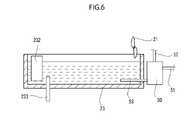
- the evaporation humidifier having the above configuration has a fine bubble generator for generating mixed water containing fine bubbles, and the fine bubble generator provides the mixed water to the water storage tank.
- bubble-sized bubble humidification air is sent into the air ejection hole provided in the water tank by an air pump to generate bubbles in the water. Bubbles in the water take in water vapor from the surroundings and become air in a high humidity state. In addition, when bubbles come out to the surface of the water, the bubbles burst and emit minute water droplets near the surface of the water. The scattered minute water droplets are vaporized in a short time by blowing air to the water surface to increase the relative humidity of the air blown on the water surface, and by sending high humidity air to the inside of the refrigerator, the humidity inside the refrigerator can be raised in a short time. can.
- the method of generating fine bubbles includes an ejector method, a swirling flow method and / or a pressure melting method.
- the ejector and / or swirl flow is naturally aspirated.
- Humidification speed is slow because mere blow humidification to the water surface is not forced humidification such as steam humidification, ultrasonic humidification and / or spray humidification.
- Fine bubbles are created in a small closed space called a fine bubble generator, but in this combination method, the water vapor mixed air is discharged from the water surface of the water tank to the larger storage space by the ventilation mechanism, so the amount of air blown by the discharge amount of fine bubbles. Is not restricted.
- the fine bubbles have a small diameter and a large number, the total contact area of gas and liquid in the bubbles is very large. Therefore, high-humidity bubbles are formed by the vaporization of water from the surrounding water to the air inside the bubbles, and the formed bubbles are released into the water and / or the water surface. In particular, after the air dissolution in water reaches saturation, the bubbles do not disappear in the water and the bubbles rise to the water surface, and the high humidity air is released to the water surface.
- the bubble diameter of fine bubbles is small, the buoyancy is small and the floating time to the water surface is long due to the viscous resistance of water. Therefore, when comparing the case where fine bubbles are formed and the case where bubbles having a normal bubble diameter are formed, more water is evaporated in the bubbles. Therefore, when the fine bubbles are formed, the air generated from the water surface is humidified to high humidity. Further, since each bubble is negatively charged, it repels each other and rises without being bonded. When the temperature inside the refrigerator and / or the water temperature is low, the amount of saturated water vapor in the air is small, so that the relative humidity inside the refrigerator can rise sufficiently rapidly even with the discharge amount of fine bubbles.
- the surface tension of the water surface is weakened by a large number of micro bubbles, and when the bubbles burst, ultrasonic waves are emitted to supply kinetic energy to the water molecules near the water surface, thereby vaporizing the water molecules.
- the water vapor released by setting the water temperature of the water storage tank as the water storage target temperature is the water vapor of the same temperature as the water temperature of the water storage tank, and the specific heat of the water vapor is about 3 times as large as that of the air, especially when the temperature inside the refrigerator is high.
- the moist air at the target temperature inside the refrigerator has a large heat capacity, which contributes to the stabilization of the temperature inside the constant temperature storage. Further, even if the internal temperature and / or the water temperature is around 0 ° C., freezing can be prevented by the water flow due to the water supply from the fine bubble-containing water discharge pipe.
- a new evaporation humidifier which is an evaporation humidifier for storage and whose power consumption and water consumption are reduced.
- shower-like or mist-like water is intermittently supplied or sprayed from the water supply device (sprayer) to the water tank, and the airflow generated by the blower mechanism is brought into contact with the water during the water supply suspension period.
- the inside of the refrigerator is suppressed or prevented from being contaminated by water droplets by alternately switching spraying and airflow generation and performing intermittent operation of the form.
- the generation of sound during water supply can be suppressed or prevented due to the spraying of minute water droplets.
- FIG. 2 is a schematic configuration side plan sectional view showing an evaporation humidifier of the storage cabinet shown in FIG.
- FIG. 1 is a diagram showing a schematic configuration of a constant temperature and high humidity storage according to an embodiment of the present invention.
- the internal temperature / humidity sensor 11 and the evaporation humidifier 20 are provided in the internal space of the constant temperature / high humidity storage 10 (hereinafter, may be referred to as “storage”). Have been placed.
- the internal temperature / humidity sensor 11 is a sensor for measuring the internal temperature (atmospheric temperature of the internal space) and the internal humidity (atmospheric humidity of the internal space) of the storage 10. Further, in the internal space of the storage 10, foods such as meat, fish and vegetables are stored as the storage S.
- FIG. 2 shows a block diagram including the control device 27.
- the evaporation humidifier 20 of the present embodiment is provided with a first blower mechanism 21 and a second blower mechanism 22, and is between the first blower mechanism 21 and the second blower mechanism 22. It is provided with a water storage tank 23 arranged in the lower part of the housing of the evaporation humidifier 20.
- Each of the first blower mechanism 21 and the second blower mechanism 22 is rotationally driven by being connected to a rotary drive device such as an electric motor and an output shaft of the rotary drive device, for example, when the blower mechanism is an axial flow fan. It is composed of a shaft and blades attached so as to project in a direction perpendicular to the axis direction of the rotation axis. In addition to the axial fan, other methods such as a centrifugal fan may be used.
- an internal temperature controller 24 is arranged on the side of the second ventilation mechanism 22 of the water storage tank 23, and the water storage tank 23 and the internal temperature controller 24 are connected by a guide cylinder 25 (guide member). There is. Further, a stirrer 26 is arranged in the water storage tank 23. Further, in the water storage tank 23, a water supply pipe 231 for supplying water W into the water storage tank 23 and a water storage temperature control for maintaining the temperature of the water W at a temperature included in the water storage target temperature range. A vessel 232 is arranged.
- the temperature inside the refrigerator can be adjusted to the target temperature range by adjusting the temperature of the stored water and / or the supply water according to the temperature inside the refrigerator, the temperature inside the refrigerator can be adjusted even if the evaporative humidifier itself is a temperature controller inside the refrigerator.
- the conditioner 24 is not an indispensable component and may be omitted as appropriate depending on the purpose, but the arrangement of the temperature controller 24 in the refrigerator provides an advantageous effect as described later.
- the water W is stored in the water storage tank 23 by the water supply pipe 231 and the water W is held at the water storage target temperature by the water storage temperature controller 232.
- the water storage target temperature range is set to, for example, a temperature range 2 ° C to 5 ° C higher than the internal temperature target temperature range.
- Water vapor is generated from the water stored in contact with the air flow in the water storage tank 23, and is introduced into the internal temperature controller 24 through the guide cylinder 25.
- the temperature of the water vapor is cooled to the target temperature by the control of the internal temperature controller 24 by the control device 27, the relative humidity rises, and the air containing the water vapor in the saturated state is the first as shown by the arrow in the figure. 2
- the temperature inside the storage 10 can be set to the target temperature and can be maintained at high humidity. Therefore, the stored material S such as food stored in the storage 10 can be controlled at a predetermined target temperature and high humidity, and its quality can be maintained.
- the supersaturated steam is blown to the water surface of the water tank 23 and comes into contact with it, and condenses and condenses the water W of the water tank 23. Raise the temperature slightly.
- the relative humidity slightly decreases, the amount of evaporation from the water surface increases, and the water vapor becomes saturated again. Therefore, the relative humidity in the storage 10 is maintained at about the saturated humidity at the temperature.
- the relative humidity of the internal space of the storage 10 becomes oversaturated by generating an airflow by the operation of the first ventilation mechanism 21 and bringing the airflow into contact with the water W (water storage) of the water storage tank 23, the oversaturated state.
- the water W evaporates and diffuses as water vapor into the internal atmosphere of the storage storage 10. ..
- the temperature of the water stored in the water tank 23 is stabilized, and the temperature inside the storage 10 can be stabilized by constantly supplying water vapor at a temperature included in the target water storage temperature range. Become.
- the evaporation humidifier 20 is used in which the cold air having the target temperature and the saturated humidity supplied into the storage 10 is blown to the water W stored in the water storage tank 23 by the fan 21. Therefore, it is possible to reduce the amount of water consumption and the power consumption as compared with the evaporator using a conventional ice maker.
- the stirrer 26 is arranged in the water tank 23, even if the airflow generated by the first blower mechanism 21 is brought into contact with the water W in the water tank 23 for a long time, it is near the water surface. Is suppressed or prevented from freezing. Therefore, the reduction in the amount of evaporation of water W due to freezing of the portion near the water surface can be suppressed. Therefore, it is possible to control the temperature inside the refrigerator and the humidity inside the refrigerator only with ordinary tap water without using an antifreeze agent.
- hydraulic stirring such as a water flow generator that injects water in water to generate a water flow can also be used.
- a heater can also be used. Intermittent operation is desirable for stirring to save energy consumption.
- an antifreeze agent it is not excluded to add an antifreeze agent to the water W stored in the water storage tank 23.
- the water W in the water storage tank 23 can be maintained in a liquid phase state, and the evaporation rate is higher than the sublimation from ice. Is planned to rise.
- the antifreeze agent is a salt such as sodium chloride and / or calcium chloride when the water temperature is around 0 ° C., and an alcohol when the water temperature is ⁇ 5 ° C. or lower.
- a hydrophilic layer may be formed on the inner surface of the water tank 23 (for example, at least a portion of the inner surface of the water tank higher than the water storage level).
- water can be generated by adsorbing and holding water on the inner surface of the water tank in which the hydrophilic layer is formed and bringing the air flow into contact with the water to generate water vapor derived from the water.
- a known hydrophilic agent such as firing a titanium oxide layer is blended on the surface of the ceramic plate.
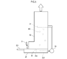
- FIG. 3 shows a schematic configuration diagram of a constant temperature and high humidity storage according to another embodiment of the present invention.
- the guide cylinder 25 (guide member) is used in whole (or partially) instead of the water supply pipe 231 arranged in the water tank 23. It differs from the first embodiment in that the water supply device 31 arranged above the water tank 23 is used in the enclosed or defined guide space, but other configurations and the like are used. It is almost the same as the first embodiment.
- shower-like or mist-like water is discharged or sprayed into the water tank 23 by the water supply device 31, and an air flow is generated by the first blower mechanism 21 between the water tank 23 and the water supply device 31.
- the amount of water vapor generated from the water is increased. Since the airflow generated by the operation of the first blower mechanism 21 flows along the guide space defined by the guide cylinder 25, the airflow is sent between the water storage tank 23 and the water supply device 31.
- the temperature of water vapor generated from water droplets generates latent heat of vaporization by lowering the temperature of surrounding water droplets. Therefore, when the water vapor diameter is small, the water vapor temperature becomes close to 0 ° C. when the water droplet water is cooled by the latent heat of vaporization, and the temperature of the water vapor generated from the water vapor drops also becomes close to 0 ° C. On the other hand, when the water droplet diameter is large, it is close to the water storage temperature of the water storage tank, and the generated water vapor temperature is also close to the water storage temperature. Therefore, the water droplet diameter is determined according to the target temperature.
- the case where the water drop diameter is small means, for example, the case where the water drop diameter is 0.5 mm to 1 mm, and the case where the water drop diameter is large means, for example, the case where the water drop diameter is 1 mm to 3 mm.
- the water droplet diameter may be measured using an intermittent irradiation laser and an ultra-high speed video camera. It is also possible to back-calculate from the airflow velocity table and / or the approximate expression of the airflow velocity and the terminal velocity so that the airborne residence time of the water droplet can be sufficiently secured.
- the airflow velocity can be obtained by measuring the moving velocity of a small piece of paper.
- water droplets obtained by blowing cold air having a target temperature and a saturated humidity to be supplied into the storage 10 into water discharged from the water supply device 31 in a shower shape by the first blowing mechanism 21 are used.
- Cold air containing water droplets is blown into the storage 10. Therefore, cold air having a target temperature and saturated humidity can be supplied to the storage 10, and the amount of water consumption and power consumption can be reduced as compared with an evaporator using a conventional ice maker.
- the airflow generated by the first blower mechanism 21 is sent out between the water storage tank 23 and the water supply device 31 through the guide space defined by the guide cylinder 25.
- the airflow will be sent in the direction opposite to the falling direction of the water droplets. Therefore, it is possible to reduce the falling speed of the water droplet and prolong the contact time between the water droplet and the air flow as compared with the state without the reverse ventilation.
- the amount of evaporation from water droplets can be increased, and the humidity inside the refrigerator can be controlled so as to be included in the target humidity range in a shorter time. Furthermore, the amount of water used can be reduced.
- the water droplets fall in the vertical direction or downward, and the airflow generated by the first blower mechanism 21 heads upward, so that the contact time between the water droplets and the airflow is extended. Therefore, the amount of evaporation derived from water droplets can be further increased, and the humidity inside the refrigerator can be controlled to be included in the target humidity range in a shorter time. Furthermore, the amount of water used can be reduced.
- Table 2 shows the diameter and terminal velocity of water droplets as they freely fall in the air.
- the terminal velocity means the speed at which the falling speed is kept constant by air resistance when the water droplet naturally falls in the air.
- the water droplet diameter of 1.0 mm to 3.0 mm in Table 2 is an approximate measured value by an experiment of the Department of Environmental Engineering, Kinki University, and the velocity of a water droplet diameter of 0.5 mm is a calculated value by an approximate formula.
- the water supply device 31 has a shower-like water. Is preferable to supply.
- the generated water droplets are exposed to the wind, a part of them is vaporized and frozen by the cold heat, and the water droplets become sherbet-like. Therefore, it is desirable that the sherbet-like water droplets are drained to a drain (not shown) without returning to the water tank 23.
- a stirrer and / or a heater can be used, and an antifreeze agent can also be used.
- the first blower mechanism 21 is used as a device for forming the blower facing the vertically falling water droplets, but another blower that functions in cooperation with the first blower mechanism 21.
- a mechanism can also be arranged.
- a hydrophilic layer may be formed on the inner surface of the water tank 23.
- water is adsorbed and held on the inner surface of the water tank 23 in which the hydrophilic layer is formed, and the airflow is brought into contact with the water to increase the amount of water vapor generated from the water.
- mist-like water may be sprayed from the water supply device 31 onto the water storage tank 23.
- the latent heat of vaporization is 7 times or more larger than the latent heat of solidification.
- the sprayed water droplets have an extremely small diameter. Therefore, it freezes by the amount of latent heat of vaporization that evaporates by the difference from saturation and becomes hoarfrost.
- the hoarfrost is adsorbed and held on the inner surface of the water tank 23 in the hydrophilic layer, thawed by a water storage temperature controller 232 arranged at the lower part of the water tank 23, for example, and controlled to a temperature included in the target temperature range.
- the water droplet temperature becomes 0 ° C. due to the latent heat of vaporization, so that there is no need for cooling, and the water storage temperature controller 232 may be omitted and tap water may be used as it is.
- shower-like or mist-like water may be intermittently sprayed toward the inner surface of the water tank 23 while continuously blowing air onto the inner surface of the water tank 23 in which the hydrophilic layer is formed. Intermittent spraying allows the fog to evaporate into the airflow during the spray stop period.
- the sprayed water droplet diameter means a size included in the range of, for example, 10 ⁇ m to 100 ⁇ m.
- the water droplet diameter was measured by an intermittent irradiation laser and an ultra-high speed video camera.
- the evaporation humidifier 20 described in the second embodiment is used as an open storage (open showcase).
- FIG. 4 shows the open storage 40.
- the outer shape of the storage 40 is composed of a U-shaped housing 41 bent at about 90 degrees. Although the description is omitted in the lower part of the housing 41, it is generally composed of a case for arranging stored items such as food.
- a cold air duct 42 is arranged in the housing 41, and an evaporation humidifier 20 is arranged in the internal space of the cold air duct 42.
- the evaporative humidifier 20 basically takes the same mode as the evaporative humidifier 20 of the second embodiment, but instead of the water supply device 31, it pumps from the water tank 23. Water W is pumped out by 33, and shower-like or mist-like water is discharged or supplied by the water supply device 31. At this time, an air flow is sent from the first air blowing mechanism 21 to the cold air duct 42, and when this air collides with the shower-shaped water W, it becomes a water droplet WS.
- the water vapor temperature generated from the water droplet WS generates vaporization latent heat by lowering the ambient water droplet water temperature. Therefore, when the water droplet diameter is small, the water vapor temperature is 0 because the water droplet water is cooled by the vaporization latent heat. It will be close to ° C, and the water vapor temperature generated from it will also be close to 0 ° C. On the other hand, when the water droplet diameter is large, it is close to the water storage temperature of the water storage tank, and the generated water vapor temperature is also close to the water storage temperature.
- the water storage temperature and the water droplet diameter are determined according to the target temperature.
- the humidity inside the refrigerator becomes close to 50% in spring and / or autumn due to water vapor leaking to the outside of the refrigerator, and it becomes drier in winter and requires a large amount of humidification, but it is higher than the target temperature.
- the humidity inside the refrigerator can be raised to saturated humidity.
- By controlling with a humidity sensor it is possible to prevent excess water from flowing out into the refrigerator.
- the cold air having the target temperature and the saturated humidity supplied into the storage 40 is blown to the water discharged from the water supply device 31 in the form of a shower or mist by the first ventilation mechanism 21.
- the cold air containing the water droplets is exhausted from the exhaust port 42A through the cold air duct 42 and applied to the stored items arranged at the lower part, and the stored items are controlled at a predetermined internal target temperature and saturated humidity. , Its quality can be maintained. Therefore, when used at around 0 ° C., the amount of water consumption and the power consumption can be reduced as compared with an evaporator using a conventional ice maker.
- the use of an antifreeze agent cannot be used for an open showcase due to the diffusion of vaporized ethanol and / or an aerosol into the room, but in the present embodiment, the antifreeze agent is particularly used. Since it is possible to maintain the quality of the stored material without having to carry it, the evaporation humidifier of the present invention can be applied to the open type storage as described above.
- the storage in the present embodiment has a saturated humidity, drying can be prevented, and at 0 ° C., the degrading enzyme activity decreases, so that the storage of meat and / or vegetables can be stored at 10 ° C. as shown in Table 1. Since the ATP decomposition temperature of fish is the slowest, it is ideal for storing fish, and at -25 ° C, it is lower than the coagulation temperature of salt water, -23 ° C, so the enzyme activity decreases, making it ideal for storing frozen products.
- the temperature at 40 ° C. is the temperature at which the growth of food poisoning bacteria stops, and is also the temperature limit for fish collagen alteration. It can also be used as a pre-dinner food storage at 40 ° C. Further, at 50 ° C to 55 ° C, the temperature at which food poisoning bacteria are killed is the limit temperature at which the protein does not deteriorate in a short time, and the temperature is close to the gelatinization temperature of starch, so that the protein does not age. Therefore, it can also be used for low temperature cooking and / or storage of gelatinized starch.
- a bubble generator (composed of a fine bubble generator or the like) for generating bubbles in the water storage may be provided.
- Bubbles in the water take in water vapor from the surroundings and become air in a high humidity state.
- the bubbles burst and emit minute water droplets near the water surface.
- the scattered minute water droplets are vaporized in a short time by bringing the airflow into contact with the water, increasing the relative humidity of the air blown on the water surface, and sending the high humidity airflow into the refrigerator raises the humidity inside the refrigerator in a short time. Can be made to.
- Constant temperature and high humidity storage 11
- Internal temperature and humidity sensor 20
- Evaporation humidifier 21 1st blower mechanism 22
- 2nd blower mechanism 23
- Water storage tank 231 Water supply pipe 232
- Water storage temperature controller 24
- Internal temperature controller 25
- Guide tube 26 Stirrer 27
- Control device 31
- Water supply device 50
- Micro bubble generator 51
- Water supply pipe 52
- Intake pipe 53
- Micro bubble-containing water discharge pipe 54 Drain pipe S Storage material W Water WS Water droplets.
Landscapes
- Engineering & Computer Science (AREA)
- Chemical & Material Sciences (AREA)
- General Engineering & Computer Science (AREA)
- Combustion & Propulsion (AREA)
- Mechanical Engineering (AREA)
- Physics & Mathematics (AREA)
- Thermal Sciences (AREA)
- Dispersion Chemistry (AREA)
- Cold Air Circulating Systems And Constructional Details In Refrigerators (AREA)
- Electrodes For Cathode-Ray Tubes (AREA)
- Physical Vapour Deposition (AREA)
- Air-Conditioning For Vehicles (AREA)
- Sorption Type Refrigeration Machines (AREA)
- Air Humidification (AREA)
- Warehouses Or Storage Devices (AREA)
Priority Applications (4)
| Application Number | Priority Date | Filing Date | Title |
|---|---|---|---|
| US18/034,512 US12529486B2 (en) | 2020-11-10 | 2021-11-10 | Evaporation heater |
| AU2021378561A AU2021378561B2 (en) | 2020-11-10 | 2021-11-10 | Evaporation heater |
| JP2022561967A JP7531932B2 (ja) | 2020-11-10 | 2021-11-10 | 蒸発加湿器 |
| EP21891913.2A EP4215852A4 (en) | 2020-11-10 | 2021-11-10 | EVAPORATIVE HEATER |
Applications Claiming Priority (2)
| Application Number | Priority Date | Filing Date | Title |
|---|---|---|---|
| JP2020187444 | 2020-11-10 | ||
| JP2020-187444 | 2020-11-10 |
Publications (1)
| Publication Number | Publication Date |
|---|---|
| WO2022102667A1 true WO2022102667A1 (ja) | 2022-05-19 |
Family
ID=81601212
Family Applications (1)
| Application Number | Title | Priority Date | Filing Date |
|---|---|---|---|
| PCT/JP2021/041388 Ceased WO2022102667A1 (ja) | 2020-11-10 | 2021-11-10 | 蒸発加湿器 |
Country Status (6)
| Country | Link |
|---|---|
| US (1) | US12529486B2 (https=) |
| EP (1) | EP4215852A4 (https=) |
| JP (1) | JP7531932B2 (https=) |
| AU (1) | AU2021378561B2 (https=) |
| TW (1) | TWI807477B (https=) |
| WO (1) | WO2022102667A1 (https=) |
Cited By (1)
| Publication number | Priority date | Publication date | Assignee | Title |
|---|---|---|---|---|
| CN117674541A (zh) * | 2023-10-30 | 2024-03-08 | 湖南科瑞变流电气股份有限公司 | 一种智能控温的整流柜及其工作方法 |
Families Citing this family (3)
| Publication number | Priority date | Publication date | Assignee | Title |
|---|---|---|---|---|
| WO2022102674A1 (ja) * | 2020-11-10 | 2022-05-19 | 株式会社Zero Food | 蒸発器 |
| CN115808040B (zh) * | 2022-11-11 | 2025-11-04 | 珠海格力电器股份有限公司 | 加湿装置及制冷设备 |
| CN120176200A (zh) * | 2025-05-16 | 2025-06-20 | 深圳市美晶科技有限公司 | 一种具有风冷加湿蒸发器的存储装置 |
Citations (15)
| Publication number | Priority date | Publication date | Assignee | Title |
|---|---|---|---|---|
| JPS58193069A (ja) * | 1982-05-07 | 1983-11-10 | 大和田 寛 | 冷蔵庫 |
| JPS60118474U (ja) * | 1984-01-20 | 1985-08-10 | サンデン株式会社 | 冷蔵シヨ−ケ−スの加湿構造 |
| JPS60118473U (ja) * | 1984-01-20 | 1985-08-10 | サンデン株式会社 | 冷蔵シヨ−ケ−スの加湿構造 |
| JPH01174875A (ja) * | 1987-12-25 | 1989-07-11 | Nippon Denso Co Ltd | 熱交換装置 |
| JPH0153264B2 (https=) | 1981-05-01 | 1989-11-13 | Mitsui Toatsu Chemicals | |
| JPH0532929U (ja) | 1991-09-27 | 1993-04-30 | 三洋電機株式会社 | 加湿器 |
| JPH06265254A (ja) * | 1993-03-12 | 1994-09-20 | Chubu Electric Power Co Inc | 高鮮度冷蔵システム |
| JPH0842960A (ja) * | 1994-06-02 | 1996-02-16 | Lg Electronics Inc | 冷蔵庫用野菜貯蔵室加湿装置 |
| JP2004003778A (ja) * | 2002-06-03 | 2004-01-08 | Matsushita Refrig Co Ltd | 保鮮庫 |
| JP2007285565A (ja) * | 2006-04-14 | 2007-11-01 | Tiger Vacuum Bottle Co Ltd | 加湿装置 |
| JP2007303708A (ja) * | 2006-05-10 | 2007-11-22 | Daiwa Industries Ltd | 高湿度冷蔵庫 |
| JP2014031905A (ja) * | 2012-08-01 | 2014-02-20 | Toshiba Corp | 家電機器 |
| KR20160096896A (ko) * | 2015-02-06 | 2016-08-17 | 주식회사 대유위니아 | 냉장고의 밀폐룸 |
| JP2017009274A (ja) * | 2015-06-17 | 2017-01-12 | 伸興テクノ株式会社 | 鮮度保持装置及びそれを備えたコンテナ |
| JP2021063805A (ja) | 2019-10-14 | 2021-04-22 | ヴェチュ インダストリテヒニク ゲーエムベーハー | 空調用試験室及び空調方法 |
Family Cites Families (11)
| Publication number | Priority date | Publication date | Assignee | Title |
|---|---|---|---|---|
| JPS60128241U (ja) * | 1984-02-07 | 1985-08-28 | 三菱重工業株式会社 | オゾナイザ付加湿器 |
| TW394368U (en) * | 1999-10-22 | 2000-06-11 | Tsai Guo Lung | Isothermal cold and hot atomized humidifier |
| JP2002253400A (ja) | 2001-03-05 | 2002-09-10 | Matsushita Refrig Co Ltd | 保鮮庫 |
| JP2005214593A (ja) | 2004-02-02 | 2005-08-11 | Yae Kogyo:Kk | 鮮度保持装置及び冷却加湿器 |
| FR2875717B1 (fr) * | 2004-09-28 | 2006-12-29 | Lionel Marc Laurent Nicolai | Dispositif de brumisation a decontamination maximale |
| JP2006317129A (ja) | 2005-05-16 | 2006-11-24 | Yae Kogyo:Kk | 高湿度保冷庫及び冷却加湿器 |
| JP2016521841A (ja) * | 2013-06-13 | 2016-07-25 | エム.エフ.クレバー ソリューションズ エルティーディーM.F.Clever Solutions Ltd | Hvacシステムのための加湿ユニット |
| AU2016203593B1 (en) * | 2015-06-02 | 2016-11-10 | Roger Foote | Medical humidifier |
| JP6947371B2 (ja) | 2016-01-14 | 2021-10-13 | 株式会社あい・あいエナジーアソシエイツ | 冷却コンテナ |
| JP6453264B2 (ja) | 2016-03-15 | 2019-01-16 | 有限会社エヌ・エヌ・エフ | 温度管理装置及び温度管理方法 |
| DE102017212412A1 (de) * | 2017-07-19 | 2019-01-24 | Weiss Umwelttechnik Gmbh | Befeuchter und Verfahren zur Konditionierung von Luft |
-
2021
- 2021-11-10 US US18/034,512 patent/US12529486B2/en active Active
- 2021-11-10 AU AU2021378561A patent/AU2021378561B2/en active Active
- 2021-11-10 JP JP2022561967A patent/JP7531932B2/ja active Active
- 2021-11-10 WO PCT/JP2021/041388 patent/WO2022102667A1/ja not_active Ceased
- 2021-11-10 EP EP21891913.2A patent/EP4215852A4/en active Pending
- 2021-11-10 TW TW110141929A patent/TWI807477B/zh active
Patent Citations (15)
| Publication number | Priority date | Publication date | Assignee | Title |
|---|---|---|---|---|
| JPH0153264B2 (https=) | 1981-05-01 | 1989-11-13 | Mitsui Toatsu Chemicals | |
| JPS58193069A (ja) * | 1982-05-07 | 1983-11-10 | 大和田 寛 | 冷蔵庫 |
| JPS60118474U (ja) * | 1984-01-20 | 1985-08-10 | サンデン株式会社 | 冷蔵シヨ−ケ−スの加湿構造 |
| JPS60118473U (ja) * | 1984-01-20 | 1985-08-10 | サンデン株式会社 | 冷蔵シヨ−ケ−スの加湿構造 |
| JPH01174875A (ja) * | 1987-12-25 | 1989-07-11 | Nippon Denso Co Ltd | 熱交換装置 |
| JPH0532929U (ja) | 1991-09-27 | 1993-04-30 | 三洋電機株式会社 | 加湿器 |
| JPH06265254A (ja) * | 1993-03-12 | 1994-09-20 | Chubu Electric Power Co Inc | 高鮮度冷蔵システム |
| JPH0842960A (ja) * | 1994-06-02 | 1996-02-16 | Lg Electronics Inc | 冷蔵庫用野菜貯蔵室加湿装置 |
| JP2004003778A (ja) * | 2002-06-03 | 2004-01-08 | Matsushita Refrig Co Ltd | 保鮮庫 |
| JP2007285565A (ja) * | 2006-04-14 | 2007-11-01 | Tiger Vacuum Bottle Co Ltd | 加湿装置 |
| JP2007303708A (ja) * | 2006-05-10 | 2007-11-22 | Daiwa Industries Ltd | 高湿度冷蔵庫 |
| JP2014031905A (ja) * | 2012-08-01 | 2014-02-20 | Toshiba Corp | 家電機器 |
| KR20160096896A (ko) * | 2015-02-06 | 2016-08-17 | 주식회사 대유위니아 | 냉장고의 밀폐룸 |
| JP2017009274A (ja) * | 2015-06-17 | 2017-01-12 | 伸興テクノ株式会社 | 鮮度保持装置及びそれを備えたコンテナ |
| JP2021063805A (ja) | 2019-10-14 | 2021-04-22 | ヴェチュ インダストリテヒニク ゲーエムベーハー | 空調用試験室及び空調方法 |
Non-Patent Citations (1)
| Title |
|---|
| See also references of EP4215852A4 |
Cited By (1)
| Publication number | Priority date | Publication date | Assignee | Title |
|---|---|---|---|---|
| CN117674541A (zh) * | 2023-10-30 | 2024-03-08 | 湖南科瑞变流电气股份有限公司 | 一种智能控温的整流柜及其工作方法 |
Also Published As
| Publication number | Publication date |
|---|---|
| AU2021378561A9 (en) | 2025-03-20 |
| EP4215852A1 (en) | 2023-07-26 |
| TWI807477B (zh) | 2023-07-01 |
| EP4215852A4 (en) | 2024-10-09 |
| AU2021378561A1 (en) | 2023-05-25 |
| AU2021378561B2 (en) | 2026-02-05 |
| TW202234000A (zh) | 2022-09-01 |
| US20240019138A1 (en) | 2024-01-18 |
| JP7531932B2 (ja) | 2024-08-13 |
| US12529486B2 (en) | 2026-01-20 |
| JPWO2022102667A1 (https=) | 2022-05-19 |
Similar Documents
| Publication | Publication Date | Title |
|---|---|---|
| WO2022102667A1 (ja) | 蒸発加湿器 | |
| JP4052352B2 (ja) | 収納庫および冷蔵庫 | |
| JP5891420B2 (ja) | 冷蔵庫 | |
| JP4725444B2 (ja) | 冷蔵庫 | |
| JP4196127B2 (ja) | 冷蔵庫 | |
| CN106152670B (zh) | 冷藏冷冻装置 | |
| JP2004125179A (ja) | 冷蔵庫及び超音波加湿器 | |
| JPH06257933A (ja) | 冷蔵庫 | |
| GB2460973A (en) | Humidity Control Within a Refrigerator by Condensing and Atomizing Storage Compartment Moisture | |
| JP2005337694A (ja) | 冷蔵庫 | |
| JP2007046888A (ja) | 冷蔵庫 | |
| JP2006145080A (ja) | 冷蔵庫 | |
| JP2006090582A (ja) | 冷蔵庫 | |
| JP7571412B2 (ja) | 加湿装置 | |
| JP5315603B2 (ja) | 冷蔵庫 | |
| JP2007240055A (ja) | 冷蔵庫 | |
| JPH10502440A (ja) | 容器内空気調整ユニットにおける改善 | |
| CN109855363B (zh) | 加湿组件、其控制方法以及冰箱 | |
| JP2009243782A (ja) | 冷蔵庫 | |
| JP6872688B2 (ja) | 冷蔵庫 | |
| JP4844326B2 (ja) | 冷蔵庫 | |
| JP2008089202A (ja) | 冷蔵庫 | |
| JP5347260B2 (ja) | 冷蔵庫 | |
| JP4471394B2 (ja) | 空気調和装置 | |
| JPH1165680A (ja) | 湿度制御方法 |
Legal Events
| Date | Code | Title | Description |
|---|---|---|---|
| 121 | Ep: the epo has been informed by wipo that ep was designated in this application |
Ref document number: 21891913 Country of ref document: EP Kind code of ref document: A1 |
|
| ENP | Entry into the national phase |
Ref document number: 2022561967 Country of ref document: JP Kind code of ref document: A |
|
| ENP | Entry into the national phase |
Ref document number: 2021891913 Country of ref document: EP Effective date: 20230418 |
|
| WWE | Wipo information: entry into national phase |
Ref document number: 18034512 Country of ref document: US |
|
| REG | Reference to national code |
Ref country code: BR Ref legal event code: B01A Ref document number: 112023008901 Country of ref document: BR |
|
| ENP | Entry into the national phase |
Ref document number: 2021378561 Country of ref document: AU Date of ref document: 20211110 Kind code of ref document: A |
|
| ENP | Entry into the national phase |
Ref document number: 112023008901 Country of ref document: BR Kind code of ref document: A2 Effective date: 20230509 |
|
| NENP | Non-entry into the national phase |
Ref country code: DE |
|
| WWG | Wipo information: grant in national office |
Ref document number: 18034512 Country of ref document: US |