WO2022102323A1 - 船舶監視システム、船舶監視方法、情報処理装置、及びプログラム - Google Patents
船舶監視システム、船舶監視方法、情報処理装置、及びプログラム Download PDFInfo
- Publication number
- WO2022102323A1 WO2022102323A1 PCT/JP2021/037789 JP2021037789W WO2022102323A1 WO 2022102323 A1 WO2022102323 A1 WO 2022102323A1 JP 2021037789 W JP2021037789 W JP 2021037789W WO 2022102323 A1 WO2022102323 A1 WO 2022102323A1
- Authority
- WO
- WIPO (PCT)
- Prior art keywords
- ship
- vessel
- risk
- risk range
- rear end
- Prior art date
- Legal status (The legal status is an assumption and is not a legal conclusion. Google has not performed a legal analysis and makes no representation as to the accuracy of the status listed.)
- Ceased
Links
Images











Classifications
-
- B—PERFORMING OPERATIONS; TRANSPORTING
- B63—SHIPS OR OTHER WATERBORNE VESSELS; RELATED EQUIPMENT
- B63B—SHIPS OR OTHER WATERBORNE VESSELS; EQUIPMENT FOR SHIPPING
- B63B43/00—Improving safety of vessels, e.g. damage control, not otherwise provided for
- B63B43/18—Improving safety of vessels, e.g. damage control, not otherwise provided for preventing collision or grounding; reducing collision damage
-
- G—PHYSICS
- G01—MEASURING; TESTING
- G01C—MEASURING DISTANCES, LEVELS OR BEARINGS; SURVEYING; NAVIGATION; GYROSCOPIC INSTRUMENTS; PHOTOGRAMMETRY OR VIDEOGRAMMETRY
- G01C21/00—Navigation; Navigational instruments not provided for in groups G01C1/00 - G01C19/00
- G01C21/20—Instruments for performing navigational calculations
- G01C21/203—Instruments for performing navigational calculations specially adapted for water-borne vessels
-
- G—PHYSICS
- G01—MEASURING; TESTING
- G01S—RADIO DIRECTION-FINDING; RADIO NAVIGATION; DETERMINING DISTANCE OR VELOCITY BY USE OF RADIO WAVES; LOCATING OR PRESENCE-DETECTING BY USE OF THE REFLECTION OR RERADIATION OF RADIO WAVES; ANALOGOUS ARRANGEMENTS USING OTHER WAVES
- G01S13/00—Systems using the reflection or reradiation of radio waves, e.g. radar systems; Analogous systems using reflection or reradiation of waves whose nature or wavelength is irrelevant or unspecified
- G01S13/02—Systems using reflection of radio waves, e.g. primary radar systems; Analogous systems
- G01S13/50—Systems of measurement based on relative movement of target
- G01S13/58—Velocity or trajectory determination systems; Sense-of-movement determination systems
- G01S13/583—Velocity or trajectory determination systems; Sense-of-movement determination systems using transmission of continuous unmodulated waves, amplitude-, frequency-, or phase-modulated waves and based upon the Doppler effect resulting from movement of targets
- G01S13/584—Velocity or trajectory determination systems; Sense-of-movement determination systems using transmission of continuous unmodulated waves, amplitude-, frequency-, or phase-modulated waves and based upon the Doppler effect resulting from movement of targets adapted for simultaneous range and velocity measurements
-
- G—PHYSICS
- G01—MEASURING; TESTING
- G01S—RADIO DIRECTION-FINDING; RADIO NAVIGATION; DETERMINING DISTANCE OR VELOCITY BY USE OF RADIO WAVES; LOCATING OR PRESENCE-DETECTING BY USE OF THE REFLECTION OR RERADIATION OF RADIO WAVES; ANALOGOUS ARRANGEMENTS USING OTHER WAVES
- G01S13/00—Systems using the reflection or reradiation of radio waves, e.g. radar systems; Analogous systems using reflection or reradiation of waves whose nature or wavelength is irrelevant or unspecified
- G01S13/88—Radar or analogous systems specially adapted for specific applications
- G01S13/93—Radar or analogous systems specially adapted for specific applications for anti-collision purposes
- G01S13/937—Radar or analogous systems specially adapted for specific applications for anti-collision purposes of marine craft
-
- G—PHYSICS
- G01—MEASURING; TESTING
- G01S—RADIO DIRECTION-FINDING; RADIO NAVIGATION; DETERMINING DISTANCE OR VELOCITY BY USE OF RADIO WAVES; LOCATING OR PRESENCE-DETECTING BY USE OF THE REFLECTION OR RERADIATION OF RADIO WAVES; ANALOGOUS ARRANGEMENTS USING OTHER WAVES
- G01S19/00—Satellite radio beacon positioning systems; Determining position, velocity or attitude using signals transmitted by such systems
- G01S19/38—Determining a navigation solution using signals transmitted by a satellite radio beacon positioning system
- G01S19/39—Determining a navigation solution using signals transmitted by a satellite radio beacon positioning system the satellite radio beacon positioning system transmitting time-stamped messages, e.g. GPS [Global Positioning System], GLONASS [Global Orbiting Navigation Satellite System] or GALILEO
- G01S19/42—Determining position
-
- G—PHYSICS
- G06—COMPUTING OR CALCULATING; COUNTING
- G06Q—INFORMATION AND COMMUNICATION TECHNOLOGY [ICT] SPECIALLY ADAPTED FOR ADMINISTRATIVE, COMMERCIAL, FINANCIAL, MANAGERIAL OR SUPERVISORY PURPOSES; SYSTEMS OR METHODS SPECIALLY ADAPTED FOR ADMINISTRATIVE, COMMERCIAL, FINANCIAL, MANAGERIAL OR SUPERVISORY PURPOSES, NOT OTHERWISE PROVIDED FOR
- G06Q10/00—Administration; Management
- G06Q10/04—Forecasting or optimisation specially adapted for administrative or management purposes, e.g. linear programming or "cutting stock problem"
- G06Q10/047—Optimisation of routes or paths, e.g. travelling salesman problem
-
- G—PHYSICS
- G06—COMPUTING OR CALCULATING; COUNTING
- G06Q—INFORMATION AND COMMUNICATION TECHNOLOGY [ICT] SPECIALLY ADAPTED FOR ADMINISTRATIVE, COMMERCIAL, FINANCIAL, MANAGERIAL OR SUPERVISORY PURPOSES; SYSTEMS OR METHODS SPECIALLY ADAPTED FOR ADMINISTRATIVE, COMMERCIAL, FINANCIAL, MANAGERIAL OR SUPERVISORY PURPOSES, NOT OTHERWISE PROVIDED FOR
- G06Q10/00—Administration; Management
- G06Q10/06—Resources, workflows, human or project management; Enterprise or organisation planning; Enterprise or organisation modelling
- G06Q10/063—Operations research, analysis or management
- G06Q10/0635—Risk analysis of enterprise or organisation activities
-
- G—PHYSICS
- G06—COMPUTING OR CALCULATING; COUNTING
- G06Q—INFORMATION AND COMMUNICATION TECHNOLOGY [ICT] SPECIALLY ADAPTED FOR ADMINISTRATIVE, COMMERCIAL, FINANCIAL, MANAGERIAL OR SUPERVISORY PURPOSES; SYSTEMS OR METHODS SPECIALLY ADAPTED FOR ADMINISTRATIVE, COMMERCIAL, FINANCIAL, MANAGERIAL OR SUPERVISORY PURPOSES, NOT OTHERWISE PROVIDED FOR
- G06Q50/00—Information and communication technology [ICT] specially adapted for implementation of business processes of specific business sectors, e.g. utilities or tourism
- G06Q50/40—Business processes related to the transportation industry
-
- G—PHYSICS
- G08—SIGNALLING
- G08G—TRAFFIC CONTROL SYSTEMS
- G08G3/00—Traffic control systems for marine craft
- G08G3/02—Anti-collision systems
-
- B—PERFORMING OPERATIONS; TRANSPORTING
- B63—SHIPS OR OTHER WATERBORNE VESSELS; RELATED EQUIPMENT
- B63B—SHIPS OR OTHER WATERBORNE VESSELS; EQUIPMENT FOR SHIPPING
- B63B49/00—Arrangements of nautical instruments or navigational aids
Definitions
- the present invention relates to a ship monitoring system, a ship monitoring method, an information processing device, and a program.
- Non-Patent Document 1 discloses a method for displaying OZT (Obstacle Zone by Target). In this method, a circular OZT having a predetermined safety separation distance as a radius is displayed on the predicted course of another ship.
- the present invention has been made in view of the above problems, and a main object thereof is a ship monitoring system and ship monitoring capable of visualizing the risk of collision or approach in the width direction orthogonal to the course direction of another ship. To provide methods, information processing equipment, and programs.
- the ship monitoring system determines the position and speed of the first ship and the first data generation unit that generates the first ship data representing the position and speed of the first ship.
- the first ship data and the first ship when it is assumed that the second data generation unit that generates the second ship data to be represented and the first ship change course in an arbitrary direction and cross the predicted course of the second ship. 2
- the first ship and the second ship in the predicted course of the second ship collide with each other based on the position of the first ship and the position of the second ship at each time point predicted from the ship data.
- a display unit for displaying a polygonal OZT having a point as at least a vertex is provided.
- the first data generation unit generates the first ship data representing the position and speed of the first ship
- the second data generation unit generates the position of the second ship.
- the second vessel data representing the speed, and the first vessel data and the second vessel data when it is assumed that the first vessel changes course in an arbitrary direction and crosses the predicted course of the second vessel.
- the risk of collision between the first vessel and the second vessel in the predicted course of the second vessel based on the position of the first vessel and the position of the second vessel at each time point predicted from Many that specify the risk range in which the represented risk value is equal to or greater than the threshold value, and have at least the representative point of the first vessel at the position corresponding to the rear end and the front end of the risk range and the rear end of the risk range as the apex.
- the square OZT is displayed on the display unit.
- the information processing apparatus of another aspect of the present invention represents the position and speed of the first ship when it is assumed that the first ship changes course in an arbitrary direction and crosses the predicted course of the second ship.
- the predicted course of the second ship based on the position of the first ship and the position of the second ship at each time point predicted from the one ship data and the second ship data representing the position and speed of the second ship.
- the risk range specifying unit that specifies the risk range in which the risk value indicating the risk of collision between the first ship and the second ship is equal to or greater than the threshold, the rear and front ends of the risk range, and the risk range.
- a display control unit for displaying a polygonal OZT having at least the representative point of the first ship at a position corresponding to the rear end on the display unit is provided.
- the first ship changes course in an arbitrary direction and crosses the predicted course of the second ship, and the first ship represents the position and speed of the first ship.
- the predicted course of the second vessel based on the position of the first vessel and the position of the second vessel at each time point predicted from the data and the second vessel data representing the position and speed of the second vessel.
- the computer is made to display the polygonal OZT having the representative point of the first ship at the corresponding position as at least the apex on the display unit.
- FIG. 1 is a block diagram showing a configuration example of the ship monitoring system 100 according to the embodiment.
- the ship monitoring method according to the embodiment is realized in the ship monitoring system 100.
- the ship monitoring system 100 is a system for monitoring ships mounted on the ship and existing in the surroundings.
- the ship equipped with the ship monitoring system 100 is an example of the first ship, and is referred to as "own ship” in the following description. Further, the ship existing around the own ship is an example of the second ship, and is referred to as “another ship” in the following description.
- speed is a vector quantity representing speed and direction (so-called ship speed vector), and "speed” is a scalar quantity.
- the ship monitoring system 100 includes an information processing device 1, a display unit 2, a radar 3, an AIS4, a GNSS receiver 5, a gyro compass 6, an ECDIS7, and an alarm unit 8. These devices are connected to a network N such as a LAN, and can communicate with each other via a network.
- a network N such as a LAN
- the information processing device 1 is a computer including a CPU, RAM, ROM, non-volatile memory, an input / output interface, and the like.
- the CPU of the information processing apparatus 1 executes information processing according to a program loaded from the ROM or the non-volatile memory into the RAM.
- the program may be supplied via an information storage medium such as an optical disk or a memory card, or may be supplied via a communication network such as the Internet or a LAN.
- the display unit 2 is, for example, a display device with a touch sensor.
- the touch sensor detects the position indicated on the screen by a finger or the like. Not limited to the touch sensor, the indicated position may be input by a trackball or the like.
- Radar 3 emits radio waves around its own ship, receives the reflected waves, and generates echo data based on the received signals. Further, the radar 3 identifies the target from the echo data and generates target tracking data (TT data) indicating the position and speed of the target.
- TT data target tracking data
- AIS Automatic Identification System 4 receives AIS data from other ships or land controls existing around its own ship. Not limited to AIS, VDES (VHFDataExchangeSystem) may be used.
- the AIS data includes the positions and speeds of other ships.
- the GNSS receiver 5 detects the position of its own ship based on the radio waves received from the GNSS (Global Navigation Satellite System).
- the gyro compass 6 detects the direction of the ship. Not limited to the gyro compass, a GPS compass or a magnetic compass may be used.
- ECDIS Electronic Chart Display and Information System 7 acquires the position of its own ship from the GNSS receiver 5 and displays the position of its own ship on the electronic chart.
- the ECDIS 7 also displays the planned route of the ship on the electronic chart.
- a GNSS plotter may be used.
- the alarm unit 8 issues an alarm when there is a risk that the own ship will collide with another ship.
- the alarm unit 8 may be, for example, an alarm by display, or an alarm by sound or light.
- the display alarm may be given by the display unit 2. That is, the display unit 2 may also serve as the alarm unit 8.
- the information processing device 1 is an independent device, but the information processing device 1 is not limited to this, and may be integrated with other devices such as ECDIS 7. That is, the functional unit of the information processing device 1 may be realized by another device such as ECDIS 7.
- the display unit 2 is also an independent device, but the present invention is not limited to this, and the display unit of another device such as ECDIS 7 may be used as the display unit 2 for displaying the image generated by the information processing device 1. ..
- the set of the GNSS receiver 5 and the ECDIS 7 is an example of the first data generation unit, and generates the own ship data representing the position and speed of the own ship. Specifically, the GNSS receiver 5 detects the position of the own ship, and the ECDIS 7 detects the speed of the own ship from the time change of the position of the own ship.
- the speed of the own ship may be detected based on the direction of the own ship detected by the gyro compass 6 and the speed of the own ship detected by the speedometer (not shown).
- the radar 3 or AIS4 is an example of the second data generation unit, and generates data of another ship representing the position and speed of another ship.
- the TT data generated by the radar 3 corresponds to the data of another ship.
- the AIS data generated by AIS4 also corresponds to the data of other ships.
- FIG. 2 is a diagram showing an example of another ship management database built in the memory of the information processing device 1.
- Other ship data generated by radar 3 or AIS4 is registered in the other ship management database.
- the other ship management database includes fields such as "other ship identifier”, "position”, “speed”, and "direction”.
- the positions and directions of other ships detected by the radar 3 are converted to the same coordinate system as GNSS.
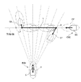
- FIG. 3 is a diagram showing a display example of a conventional OZT.
- OZT (Obstacle Zone by Target) is a zone in which the navigation of the own ship may be obstructed by another ship, and is displayed on the predicted course of the other ship.
- a plurality of circular OZTs are displayed in a row in a range where the risk of collision is high in the predicted course of another ship, so that the user can grasp the risk of collision or approach in the course direction.
- Cheap since the width of the OZT is constant in the width direction orthogonal to the course direction, it is difficult for the user to grasp the risk of collision or approach in the width direction.
- Fig. 3 shows the situation where the own ship joins the sea area where many other ships are navigating. According to this, when the own ship takes the route A, it seems that there is sufficient space, but in reality, other ships approach both the left and right sides, and the operator feels nervous. On the other hand, when the own ship takes Route B, it seems that there is not enough space at first glance because there are symbols of other ships on the way, but in reality, other ships are more than in the case of Route A. The ship operator is less likely to feel nervous because he does not approach.
- FIG. 4 is a diagram showing a configuration example of the information processing apparatus 1 according to the embodiment, which realizes the ship monitoring method according to the embodiment.
- the information processing apparatus 1 includes a risk range specifying unit 11, a display control unit 12, and a size data holding unit 13.
- the risk range specifying unit 11 and the display control unit 12 are realized by the CPU of the information processing device 1 executing information processing according to a program.
- the size data holding unit 13 is built in the memory of the information processing device 1.
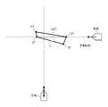
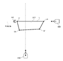
- the risk range specifying unit 11 determines the position and other of the own ship at each time point predicted from the own ship data and the other ship data when it is assumed that the own ship changes course in an arbitrary direction and crosses the predicted course of the other ship. Based on the position of the ship, the risk range L in which the risk value of the collision between the own ship and the other ship is equal to or higher than the threshold value is specified in the predicted course of the other ship (see FIG. 8A).
- the display control unit 12 is located at the rear end LR and the front end LF of the risk range L specified by the risk range specifying unit 11, the representative point SF of the own ship at the position corresponding to the rear end LR, and the position corresponding to the front end LF.
- a rectangular OZT having the representative point SR of the own ship as the apex is displayed on the display unit 2 (see FIG. 8B).
- the size data includes the lengths L1 and L2 of the ship area S occupied by the own ship and the lengths PL1 and PL2 of the warning area P set around the own ship.
- the ship area S occupied by the own ship is an area representing the physical size of the own ship.
- the ship area S of the own ship is represented by a line segment from the front end to the rear end of the own ship.
- the length L1 is the length from the reference position RP of the own ship to the front end of the own ship
- the length L2 is the length from the reference position RP of the own ship to the rear end of the own ship.
- the reference position RP of the own ship corresponds to the antenna position of the GNSS receiver 5 (see FIG. 1).
- the risk value is set to 1 which is the maximum in the ship area S of the own ship.
- the warning area P set around the own ship is set in front of and behind the own ship.
- the warning area P of the own ship is represented by a line segment extending forward from the front end of the own ship and a line segment extending rearward from the rear end of the own ship.
- the length PL1 is the length from the front end of the own ship to the front end of the warning area P
- the length PL2 is the length from the rear end of the own ship to the rear end of the warning area P.
- the caution area P does not have to be set behind the own ship. That is, the length PL2 may be 0. Further, the caution area P may not be set in front of the own ship. That is, the length PL1 may be 0.
- the caution area P is set according to the area where the operator feels that the invasion of another ship is psychologically unfavorable, although physical contact with another ship does not occur.
- the alert area P can be likened to a personal space where a person feels uncomfortable when approached by another person.
- the risk value is set to 1 in the caution area P as well as the ship area S.
- the risk value may be set so that the risk value gradually decreases as the distance from the own ship increases in the caution area P.
- the ship area S and the warning area P of the own ship are represented by line segments in the front-rear direction, but the limitation is not limited to this, and the length in the width direction is also added to the ship area S and the warning area S of the own ship.
- the region P may be represented by a rectangular region, a line segment cross type in which a line segment in the front-back direction and a line segment in the width direction intersect, or an ellipse, an oval, or an oval shape. It may be represented by a bumper type.
- the ship area occupied by the other ship and the caution area set around the other ship are set.
- the length in the front-rear direction of the other ship for example, the length of the ship included in the AIS data may be used, or a predetermined length according to the ship type included in the AIS data may be used. Not limited to this, the length in the front-rear direction of another ship may be estimated from, for example, the echo data of the radar 3.
- the reference position of the other ship is, for example, a predetermined position such as the center of the ship area of the other ship.
- FIG. 7 is a diagram showing an example of a specific processing procedure executed by the risk range specifying unit 11.
- the information processing apparatus 1 functions as the risk range specifying unit 11 by executing the process shown in the figure according to the program.
- 8A and 8B are diagrams showing a calculation example and a display example of OZT.
- the risk range specifying unit 11 acquires the own ship data (S11), and calculates the predicted position of the own ship at each time point based on the acquired own ship data (S12).
- the calculation of the predicted position of the own ship is performed under the assumption that the own ship will change its course in any direction at the current position while maintaining the speed. That is, while the magnitude of the own ship speed vector is constant, the direction of the own ship speed vector changes to an arbitrary direction at the reference time point, and thereafter, it sails in a certain direction from the own ship position at the reference time point. Is assumed to continue. Therefore, the predicted position of the ship at each time point exists on a concentric circle centered on the position of the ship at the reference time. The radius of the circle is expressed by the product of the elapsed time from the reference time and the magnitude of the own ship speed vector.
- the predicted position of the ship at each time point is represented by multiple discrete concentric circles calculated for each of the multiple discrete time points. Not limited to this, the predicted position of the own ship at each time point may be expressed by a circular formula including the elapsed time from the reference time point (details will be described later).
- the predicted position of the own ship is calculated on the assumption that the speed of the own ship is constant, but the predicted position of the own ship is not limited to this, and the speed of the own ship changes with time. It may be treated as a variable. That is, if the predicted position of the own ship is obtained according to the elapsed time from the reference time, the speed of the own ship does not have to be constant. For example, the speed of the ship may gradually increase or decrease over time.
- the risk range specifying unit 11 acquires the data of the other ship (S13), and calculates the predicted position of the other ship at each time point based on the acquired data of the other ship (S14).
- the calculation of the predicted position of another ship is performed under the assumption that the other ship will maintain the speed from the current position and navigate. That is, it is assumed that the magnitude and direction of the speed vector of the other ship are constant and the navigation is continued from the position of the other ship at the reference time. Therefore, the predicted position of the other ship at each time point exists on a straight line extending the speed vector of the other ship passing through the position of the other ship at the reference time point.
- the predicted position of another ship at each time point is represented by a plurality of discrete points arranged on a straight line calculated for each of the multiple discrete time points.
- the predicted position of the other ship at each time point may be expressed by a linear function passing through the position of the other ship at the reference time point (details will be described later).
- the predicted position of the other ship is calculated on the assumption that the speed of the other ship is constant, but the predicted position is not limited to this, and at least one of the speed and the direction of the other ship is time. It may be treated as a variable that changes according to. That is, the speed of the other ship does not have to be constant as long as the predicted position of the other ship is obtained according to the elapsed time from the reference time. For example, the speed of another vessel may gradually increase or decrease over time. Further, the other ship may change the course in a predetermined direction or may turn at a predetermined ROT (Rate of Turn).
- ROT Rate of Turn
- the risk range specifying unit 11 calculates the separation distance between the predicted position of the own ship and the predicted position of another ship at each time point (S15).
- the separation distance is expressed by the distance between the point representing the predicted position of the own ship and the point representing the predicted position of another ship.
- the risk range specifying unit 11 can use the circle representing the predicted position of the own ship at a certain point in time to display another ship at the same point. Select the position closest to the predicted position of and calculate the separation distance.
- the risk range specifying unit 11 acquires size data from the size data holding unit 13 (S16), and calculates a risk value indicating the risk of collision between the own ship and another ship based on the separation distance and the size data. (S17).
- the risk range specifying unit 11 sets the ship area S and the warning area P of the ship using the size data of the ship (see FIGS. 5 and 6), and sets the ship area S or the ship area S of the ship. It is determined whether or not the caution area P includes a point representing the predicted position of another ship.
- the ship of the own ship is the distance L1 or less from the reference position RP of the own ship to the front end of the ship area S. It is determined that the area S includes the predicted position of another ship. Further, when the separation distance is larger than the distance L1 and is equal to or less than the distance L1 + PL1 from the reference position RP of the own ship to the front end of the warning area P, the warning area P of the own ship includes the predicted position of another ship. It is judged.
- the separation distance of the own ship is equal to or less than the distance L2 from the reference position RP of the own ship to the rear end of the ship area S. It is determined that the ship area S includes the predicted position of another ship. Further, when the separation distance is larger than the distance L2 and the distance from the reference position RP of the own ship to the rear end of the warning area P is L2 + PL2 or less, the predicted position of the other ship is included in the warning area P of the own ship. Is determined.
- Whether the predicted position of the own ship is in front of or behind the predicted course of another ship can be determined by the positive and negative signs of the separation distance.
- the separation distance between the point representing the predicted position of the own ship and the point representing the predicted position of the other ship is obtained, but as shown in FIGS. 10 and 11, the ship area BS or the caution area BP of the other ship is obtained.
- the distance between the point representing the predicted position of the own ship and the front end or the rear end of the ship area BS or the caution area BP of another ship may be obtained.
- the risk range specifying unit 11 sets the risk value to 1 when the point indicating the predicted position of another ship is included in the ship area S or the caution area P of the own ship, and sets the risk value to 1 when it is not included.
- the minimum value is 0 (see FIG. 6A).
- the threshold value is set between 0 and 1, and the risk value is equal to or higher than the threshold value when a point representing the predicted position of another ship is included in the ship area S or the caution area P of the own ship.
- the risk value may be set so as to gradually decrease as the distance from the own ship increases (see FIG. 6 (b)).
- the risk value becomes equal to or higher than the threshold value when a point representing the predicted position of the ship is included and the ship area S of the own ship is approached to some extent.
- the calculation by the risk range specifying unit 11 may be performed as follows. Here, a case where the position where the front end of the ship area of the own ship and the rear end of the ship area of another ship abut is calculated will be described as an example.
- Vo be the velocity vector of the own ship.
- Lof the length from the reference position of the own ship to the front end.
- the position of the front end of the ship area of the ship after the lapse of time t is the origin (0,0). It is represented by the circumference of the radius Vot + Lof centered on.
- V t be the velocity vector of the own ship.
- L tb The length from the reference position of another ship to the rear end.
- the position CP of the rear end of the ship area of the other ship after the lapse of time t is expressed by the following formula 1.
- V tx is the x component of V t
- V ty is the y component of V t .
- the risk range specifying unit 11 identifies the risk range L in which the risk value calculated in S17 is equal to or higher than the threshold value (S18), and is at a position corresponding to the rear end LR, the front end LF, and the rear end LR of the risk range L.
- the representative point SF of the own ship and the representative point SR of the own ship at the position corresponding to the front end LF are specified (S19).
- the front-back direction of the risk range L corresponds to the front-back direction of another ship.
- the risk value becomes equal to or higher than the threshold value when the ship area S or the warning area P of the own ship includes a point indicating the predicted position of another ship, and therefore, as shown in FIG. 8A.
- the rear end LR of the risk range L is a position where the front end of the warning area P of the own ship comes into contact with a point representing the position of another ship.
- the front end LF of the risk range L is a position where the rear end of the warning area P of the own ship comes into contact with a point representing the position of another ship.
- the representative point SF of the own ship at the position corresponding to the rear end LR of the risk range L is the front end of the ship area S of the own ship.
- the position of the own ship corresponding to the rear end LR of the risk range L is the position of the own ship when the front end of the warning area P of the own ship is located at the rear end LR of the risk range L.
- the representative point SF of the own ship is not limited to the front end of the ship area S of the own ship, but is the reference position RP (see FIG. 5), the rear end of the ship area S of the own ship, the rear end of the warning area P of the own ship, etc. May be.
- the representative point SF of the own ship at the position corresponding to the front end LF of the risk range L is the rear end of the ship area S of the own ship.
- the position of the own ship corresponding to the front end LF of the risk range L is the position of the own ship when the rear end of the warning area P of the own ship is located at the front end LF of the risk range L.
- the representative point SF of the own ship is not limited to the rear end of the ship area S of the own ship, but is the reference position RP (see FIG. 5), the front end of the ship area S of the own ship, the front end of the warning area P of the own ship, and the like. There may be.
- the risk range specifying unit 11 is the representative point SF of the own ship at the position corresponding to the rear end LR and the front end LF of the risk range L, the rear end LR, and the representative point SR of the own ship at the position corresponding to the front end LF.
- the position is output to the display control unit 12 as the apex of the OZT, and the process is terminated. If there are a plurality of other ships, the processes S13 to S19 are executed for each of the plurality of other ships.
- the display control unit 12 has the rear end LR and the front end LF of the risk range L specified by the risk range specifying unit 11, the representative point SF of the own ship at the position corresponding to the rear end LR, and the front end.
- the rectangular OZT having the representative point SR of the own ship at the position corresponding to the LF as the apex is displayed on the screen of the display unit 2.
- the corners of the OZT may be rounded.
- the OZT does not have a fixed width, but has a shape that overhangs to the side where the own ship approaches at each of the front part and the rear part of the risk range L.
- the OZT overhangs to the predicted position side of the own ship at the rear of the risk range L. ..
- the OZT overhangs to the predicted position side of the own ship at the front part of the risk range L.
- the risk range specifying unit 11 may determine whether or not the ship area S or the caution range P of the own ship overlaps with the ship area BS of another ship, as shown in FIG.
- the rear end LR of the risk range L is a position where the front end of the warning area P of the own ship comes into contact with the rear end of the ship area BS of another ship.
- the front end LF of the risk range L is a position where the rear end of the warning area P of the own ship comes into contact with the front end of the ship area BS of another ship.
- the risk range specifying unit 11 may determine whether or not the ship area S or the warning range P of the own ship overlaps with the ship area BS or the warning range BP of another ship.
- the rear end LR of the risk range L is a position where the front end of the warning area P of the own ship comes into contact with the rear end of the warning area BP of another ship.
- the front end LF of the risk range L is a position where the rear end of the warning area P of the own ship comes into contact with the front end of the warning area BP of another ship.
- the risk range specifying unit 11 does not set the warning area P of the own ship, and whether or not the ship area S of the own ship overlaps with the point indicating the position of another ship, the ship area BS, or the warning range BP. May be determined. Further, the risk range specifying unit 11 does not set the ship area S and the warning area P of the own ship, and the point indicating the position of the own ship represents the position of another ship, the ship area BS, or the warning range BP. It may be determined whether or not it overlaps with.
- the matching relationship between the own ship and another ship is not limited to the above example, and as shown in FIG. 12, for example, in both the front end LF and the rear end LR of the risk range L, the front end of the warning area P of the own ship. May be in contact with the rear end of the ship area BS (or warning area BP) of another ship.
- the representative point SF of the own ship at the position corresponding to the front end LF of the risk range L is the front end of the ship area S of the own ship, the reference position, the rear end of the ship area S of the own ship, or the warning of the own ship.
- the rear end of the region P and the like is the representative point SF of the own ship at the position corresponding to the front end LF of the risk range L.
- the rear end LR of the risk range L is the rear end of the warning area P of the own ship.
- the position is in contact with the front end of the ship area BS (or warning area BP) of another ship, and the front end LF of the risk range L is such that the front end of the warning area P of the own ship is the ship area BS (or warning area BP) of another ship. It may be in a position where it abuts on the rear end.
- the representative point SF of the own ship at the position corresponding to the rear end LR of the risk range L is the rear end of the ship area S of the own ship, the reference position, the front end of the ship area S of the own ship, or the own ship. It is the front end of the caution area P and the like.
- the representative point SF of the own ship at the position corresponding to the front end LF of the risk range L is the front end of the ship area S of the own ship, the reference position, the rear end of the ship area S of the own ship, or the warning area of the own ship. For example, the rear end of P.
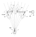
- FIG. 14 shows a display example when the quadrangular OZT according to the present embodiment is displayed in the same situation as the conventional example of FIG.
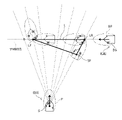
- 15A and 15B are diagrams showing a calculation example and a display example of OZT according to the first modification.
- the risk range specifying unit 11 determines the rear end LR and the front end LF of the risk range L, and the representative point SF of the own ship at the position corresponding to the rear end LR. It is output to the display control unit 12 as the position of the apex of the OZT.
- the display control unit 12 determines the rear end LR and the front end LF of the risk range L specified by the risk range specifying unit 11, and the representative point SF of the own ship at the position corresponding to the rear end LR.
- the triangular OZT as the apex is displayed on the screen of the display unit 2.
- the corners of the OZT may be rounded.
- the representative point SR (see FIGS. 8A and 8B) of the own ship at the position corresponding to the front end LF of the risk range L is not included in the apex of the OZT.
- the rear end LR of the risk range L is a position where the front end of the warning area P of the own ship comes into contact with the rear end of the ship area BS of another ship.
- the front end LF of the risk range L is a position where the rear end of the ship area S of the own ship comes into contact with the front end of the warning area BP of another ship.
- the figure shows an example in which the warning zone P is not set behind the own ship or another ship.
- the positions of the rear end LR and the front end LF of the risk range L are not limited to this, and may be determined in various ways as described above.
- the representative point SF of the own ship at the position corresponding to the rear end LR of the risk range L is the reference position RP of the own ship (see FIG. 5).
- the representative point SF of the own ship may be the front end or the rear end of the ship area S of the own ship.
- the front end LF of the risk range L is at a position where the rear end of the ship area S of the own ship comes into contact with the front end of the warning area BP of another ship, so that the front end of the risk range L is in front of the risk range L. , It becomes a matchmaking relationship that the own ship crosses the front of the other ship.
- the rear end LR of the risk range L is a position where the front end of the warning area P of the own ship comes into contact with the rear end of the ship area BS of another ship, so that the own ship is behind the risk range L. It will be a matchmaking relationship that crosses the rear of other ships.
- the OZT gradually narrows in width toward the front end LF of the risk range L, and has a sharp shape toward the front of the risk range L, that is, a shape pointing to the front of the risk range L. There is.
- the user sees the OZT, he / she can grasp not only the risk of collision but also the matchmaking relationship between the own ship and another ship before and after the OZT.
- the own ship advances to the sharp side of the OZT, that is, the front side of the OZT, it can be grasped that the own ship has a matchmaking relationship across the front of the other ship.
- the blunt side of the OZT the side having the side extending toward the own ship
- the own ship becomes a matchmaking relationship across the rear of the other ship. be able to.
- the display control unit 12 may display the index MK in association with the front end LF of the risk range L.
- the index MK has a shape pointing to the front of the risk range L.
- the index MK has, for example, a mountain shape, and the direction is indicated by the direction of the convex portion.
- the index MK may have a shape such as an arrow shape or a boomerang shape.
- the index MK is associated with the front end LF of the risk range L by being displayed in the vicinity of the front end LF of the risk range L. Specifically, the index MK is arranged in front of the OZT on the predicted course of another ship and points in the course direction. Not limited to this, the index MK may be connected to the front end LF of the risk range L, or may be connected via a leader wire.
- index MK By displaying such an index MK, it becomes easier for the user to grasp the traveling direction of another ship. In addition, by displaying the index MK, it becomes easier for the user to understand that when the own ship advances to the front side of the OZT, the own ship crosses the front of the other ship.
- 16A and 16B are diagrams showing calculation examples and display examples of other OZTs. As shown in FIG. 16A, when the ship speed of another ship is high, the front end of the warning area P of the own ship is behind the ship area BS of the other ship in both the front end LF and the rear end LR of the risk range L. It may hit the edge.
- the risk range specifying unit 11 is the representative point SF of the own ship at the position corresponding to the rear end LR and the front end LF of the risk range L, the rear end LR, and the representative of the own ship at the position corresponding to the front end LF.
- the point SR is output to the display control unit 12 as the position of the apex of the OZT.
- the display control unit 12 is at the rear end LR and the front end LF of the risk range L, the representative point SF of the own ship at the position corresponding to the rear end LR, and the self at the position corresponding to the front end LF.
- the rectangular OZT having the representative point SR of the ship as the apex is displayed on the screen of the display unit 2.
- the display control unit 12 may display the index MK in association with the front end LF of the risk range L. By displaying such an index MK, it becomes easier for the user to grasp the traveling direction of another ship.
- FIG. 17 is a diagram showing a display example of OZT according to the second modification.
- the figure shows an example in which OZT1 representing the risk of collision between the own ship and the other ship 1 and OZT2 representing the risk of collision between the own ship and the other ship 2 partially overlap.
- the display control unit 12 makes the display mode such as shading, color, texture, etc. different from each other in the overlapping portion OL of the OZT1 and 2 and the other portion. For example, the display control unit 12 displays the overlapping portion OL darker than the other portions. By creating each of OZT1 and 2 in a semi-transparent manner and displaying them in an overlapping manner, the overlapping portion OL is displayed darker than the other portions.
- the overlapping part OL in which the own ship can collide with the plurality of other ships 1 and 2 is displayed separately from the other parts, so that the risk of collision is higher. It becomes easy for the user to grasp the zone.
- 18A to 18C are diagrams showing calculation examples and display examples of other OZTs.
- the collision range L1 (see FIG. 18A) where the ship area S of the own ship and the ship area BS of the other ship overlap, and the warning area P of the own ship and the warning area BP of the other ship overlap.
- the approach range L2 (see FIG. 18B) is specified as the risk range.
- the rear end L1R of the collision range L1 is a position where the front end of the ship area S of the own ship comes into contact with the rear end of the ship area BS of another ship.
- the front end L1F of the collision range L1 is a position where the rear end of the ship area S of the own ship comes into contact with the front end of the ship area BS of another ship.
- the representative point S1F of the own ship at the position corresponding to the rear end L1R of the collision range L1 and the representative point S1R of the own ship at the position corresponding to the front end L1F of the collision range L1 are the reference position RP of the own ship. (See FIG. 5).
- the rear end L2R of the approach range L2 is a position where the front end of the warning area P of the own ship comes into contact with the rear end of the warning area BP of another ship.
- the front end L2F of the approach range L2 is a position where the rear end of the warning area P of the own ship comes into contact with the front end of the warning area BP of another ship.
- the representative point S2F of the own ship at the position corresponding to the rear end L2R of the approach range L2 and the representative point S1R of the own ship at the position corresponding to the front end L1F of the collision range L1 are the reference position RP of the own ship. (See FIG. 5).
- the display control unit 12 has a quadrangular OZT1 having vertices at each point L1R, L1F, S1F, S1R related to the collision range L1 and a quadrangular OZT2 having vertices at each point L2R, L2F, S2F, S2R related to the approach range L2. Is displayed on the screen of the display unit 2.
- OZT1 related to the collision range L1 is a zone where there is a high possibility that a collision between the own ship and another ship will occur in the future.
- OZT2 related to the approach range L2 is a zone in which the possibility of collision is not as high as that of OZT1, but the possibility that the own ship and another ship will approach each other in the future is high.
- OZT1 is included in OZT2.
- the display control unit 12 makes the display modes such as shading, color, and texture different from each other between the OZT1 related to the collision range L1 and the OZT2 related to the approach range L2. For example, the display control unit 12 displays OZT1 darker than OZT2. By creating each of OZT1 and 2 in a semi-transparent manner and displaying them in an overlapping manner, OZT1 is displayed darker than OZT2.
- 1 information processing device 2 display unit, 3 radar, 4 AIS, 5 GNSS receiver, 6 gyro compass, 7 ECDIS, 8 alarm unit, 11 risk range identification unit, 12 display control unit, 13 size data retention unit, 100 ship Monitoring system
Landscapes
- Engineering & Computer Science (AREA)
- Radar, Positioning & Navigation (AREA)
- Remote Sensing (AREA)
- Physics & Mathematics (AREA)
- General Physics & Mathematics (AREA)
- Business, Economics & Management (AREA)
- Ocean & Marine Engineering (AREA)
- Human Resources & Organizations (AREA)
- Economics (AREA)
- Strategic Management (AREA)
- Computer Networks & Wireless Communication (AREA)
- Health & Medical Sciences (AREA)
- Mechanical Engineering (AREA)
- Combustion & Propulsion (AREA)
- Chemical & Material Sciences (AREA)
- Tourism & Hospitality (AREA)
- Theoretical Computer Science (AREA)
- Marketing (AREA)
- General Business, Economics & Management (AREA)
- Electromagnetism (AREA)
- Public Health (AREA)
- Entrepreneurship & Innovation (AREA)
- Operations Research (AREA)
- Primary Health Care (AREA)
- Development Economics (AREA)
- Game Theory and Decision Science (AREA)
- General Health & Medical Sciences (AREA)
- Quality & Reliability (AREA)
- Automation & Control Theory (AREA)
- Educational Administration (AREA)
- Traffic Control Systems (AREA)
Priority Applications (5)
| Application Number | Priority Date | Filing Date | Title |
|---|---|---|---|
| JP2022561344A JP7724234B2 (ja) | 2020-11-12 | 2021-10-12 | 船舶監視システム、船舶監視方法、情報処理装置、及びプログラム |
| KR1020237011966A KR20230106587A (ko) | 2020-11-12 | 2021-10-12 | 선박 감시 시스템, 선박 감시 방법, 정보 처리 장치, 및 프로그램 |
| EP21891570.0A EP4246493A4 (en) | 2020-11-12 | 2021-10-12 | Vessel monitoring system, vessel monitoring method, information processing device, and program |
| CN202180073646.0A CN116508087B (zh) | 2020-11-12 | 2021-10-12 | 船舶监视系统、船舶监视方法、信息处理装置以及计算机程序产品 |
| US18/196,440 US12304599B2 (en) | 2020-11-12 | 2023-05-12 | Ship monitoring system, ship monitoring method, and information processing device |
Applications Claiming Priority (2)
| Application Number | Priority Date | Filing Date | Title |
|---|---|---|---|
| JP2020188726 | 2020-11-12 | ||
| JP2020-188726 | 2020-11-12 |
Related Child Applications (1)
| Application Number | Title | Priority Date | Filing Date |
|---|---|---|---|
| US18/196,440 Continuation-In-Part US12304599B2 (en) | 2020-11-12 | 2023-05-12 | Ship monitoring system, ship monitoring method, and information processing device |
Publications (1)
| Publication Number | Publication Date |
|---|---|
| WO2022102323A1 true WO2022102323A1 (ja) | 2022-05-19 |
Family
ID=81601872
Family Applications (1)
| Application Number | Title | Priority Date | Filing Date |
|---|---|---|---|
| PCT/JP2021/037789 Ceased WO2022102323A1 (ja) | 2020-11-12 | 2021-10-12 | 船舶監視システム、船舶監視方法、情報処理装置、及びプログラム |
Country Status (6)
| Country | Link |
|---|---|
| US (1) | US12304599B2 (https=) |
| EP (1) | EP4246493A4 (https=) |
| JP (1) | JP7724234B2 (https=) |
| KR (1) | KR20230106587A (https=) |
| CN (1) | CN116508087B (https=) |
| WO (1) | WO2022102323A1 (https=) |
Cited By (2)
| Publication number | Priority date | Publication date | Assignee | Title |
|---|---|---|---|---|
| WO2024262223A1 (ja) * | 2023-06-21 | 2024-12-26 | 古野電気株式会社 | 航行支援装置、航行支援方法、及びプログラム |
| US12391346B2 (en) | 2022-06-09 | 2025-08-19 | Furuno Electric Co., Ltd. | Obstruction zone generation device and method |
Families Citing this family (2)
| Publication number | Priority date | Publication date | Assignee | Title |
|---|---|---|---|---|
| WO2022249632A1 (ja) * | 2021-05-26 | 2022-12-01 | 古野電気株式会社 | 船舶監視装置、船舶監視方法、及びプログラム |
| CN117355881A (zh) * | 2021-06-15 | 2024-01-05 | 古野电气株式会社 | 船舶监视系统、船舶监视方法、信息处理装置以及程序 |
Citations (4)
| Publication number | Priority date | Publication date | Assignee | Title |
|---|---|---|---|---|
| JPH07129872A (ja) * | 1993-11-01 | 1995-05-19 | Unyusho Senpaku Gijutsu Kenkyusho | 船舶衝突予防航行支援装置 |
| JPH07246998A (ja) * | 1994-03-08 | 1995-09-26 | Tokimec Inc | 船舶用航行支援装置 |
| JP2000128073A (ja) * | 1998-10-27 | 2000-05-09 | Japan Radio Co Ltd | 自動衝突予防援助装置 |
| JP2016049903A (ja) * | 2014-09-01 | 2016-04-11 | 東洋建設株式会社 | 航法支援装置 |
Family Cites Families (15)
| Publication number | Priority date | Publication date | Assignee | Title |
|---|---|---|---|---|
| JP3395105B2 (ja) * | 1997-03-14 | 2003-04-07 | 三井造船株式会社 | 船舶の危険行動評価装置 |
| US6408248B1 (en) * | 2000-07-11 | 2002-06-18 | Northrop Grumman Corporation | Apparatus and method for providing accurate boundaries of predicted areas of danger for collision avoidance |
| JP4925525B2 (ja) * | 2001-08-03 | 2012-04-25 | 古野電気株式会社 | 他船表示装置 |
| JP6953108B2 (ja) * | 2015-09-08 | 2021-10-27 | 古野電気株式会社 | 情報表示装置及び情報表示方法 |
| KR101800002B1 (ko) * | 2016-06-29 | 2017-11-21 | 한국해양과학기술원 | 방사형 그래프를 이용한 선박의 충돌 위험도 표시방법 |
| JP6618562B2 (ja) * | 2018-03-22 | 2019-12-11 | 東京計器株式会社 | 船舶用航行支援装置 |
| CN108281043B (zh) * | 2018-03-23 | 2021-04-27 | 上海海事大学 | 一种船舶碰撞风险预警系统及预警方法 |
| CN108847054A (zh) * | 2018-06-15 | 2018-11-20 | 武汉理工大学 | 基于无人机的船舶碰撞预警系统 |
| JP7080320B2 (ja) * | 2018-06-27 | 2022-06-03 | 古野電気株式会社 | 衝突警報装置及び衝突警報方法 |
| JP6715899B2 (ja) * | 2018-09-05 | 2020-07-01 | 三菱電機株式会社 | 衝突回避装置 |
| CN109697892B (zh) * | 2019-02-22 | 2021-04-27 | 湖北大学 | 一种时空感知的船舶碰撞风险智能预警方法 |
| CN111186549B (zh) * | 2020-01-15 | 2021-08-17 | 大连海事大学 | 一种具有船舶避碰功能的航向自动舵控制系统 |
| JP7259172B2 (ja) * | 2020-03-16 | 2023-04-18 | 三井E&S造船株式会社 | 航路生成装置 |
| US11433885B1 (en) * | 2020-08-20 | 2022-09-06 | Zoox, Inc. | Collision detection for vehicles |
| US11794732B2 (en) * | 2020-11-05 | 2023-10-24 | Zoox, Inc. | Allocation of safety system resources based on probability of intersection |
-
2021
- 2021-10-12 WO PCT/JP2021/037789 patent/WO2022102323A1/ja not_active Ceased
- 2021-10-12 KR KR1020237011966A patent/KR20230106587A/ko active Pending
- 2021-10-12 EP EP21891570.0A patent/EP4246493A4/en active Pending
- 2021-10-12 JP JP2022561344A patent/JP7724234B2/ja active Active
- 2021-10-12 CN CN202180073646.0A patent/CN116508087B/zh active Active
-
2023
- 2023-05-12 US US18/196,440 patent/US12304599B2/en active Active
Patent Citations (4)
| Publication number | Priority date | Publication date | Assignee | Title |
|---|---|---|---|---|
| JPH07129872A (ja) * | 1993-11-01 | 1995-05-19 | Unyusho Senpaku Gijutsu Kenkyusho | 船舶衝突予防航行支援装置 |
| JPH07246998A (ja) * | 1994-03-08 | 1995-09-26 | Tokimec Inc | 船舶用航行支援装置 |
| JP2000128073A (ja) * | 1998-10-27 | 2000-05-09 | Japan Radio Co Ltd | 自動衝突予防援助装置 |
| JP2016049903A (ja) * | 2014-09-01 | 2016-04-11 | 東洋建設株式会社 | 航法支援装置 |
Non-Patent Citations (2)
| Title |
|---|
| IMAZU, HAYAMAFUKUTO, JUNJINUMANO, MASAYOSHI: "Obstacle Zone by Targets and Its Display", THE JOURNAL OF JAPAN INSTITUTE OF NAVIGATION, vol. 107, 2002, pages 191 - 197 |
| See also references of EP4246493A4 |
Cited By (2)
| Publication number | Priority date | Publication date | Assignee | Title |
|---|---|---|---|---|
| US12391346B2 (en) | 2022-06-09 | 2025-08-19 | Furuno Electric Co., Ltd. | Obstruction zone generation device and method |
| WO2024262223A1 (ja) * | 2023-06-21 | 2024-12-26 | 古野電気株式会社 | 航行支援装置、航行支援方法、及びプログラム |
Also Published As
| Publication number | Publication date |
|---|---|
| JP7724234B2 (ja) | 2025-08-15 |
| KR20230106587A (ko) | 2023-07-13 |
| EP4246493A4 (en) | 2024-10-16 |
| CN116508087B (zh) | 2026-04-24 |
| US12304599B2 (en) | 2025-05-20 |
| EP4246493A1 (en) | 2023-09-20 |
| US20230278681A1 (en) | 2023-09-07 |
| JPWO2022102323A1 (https=) | 2022-05-19 |
| CN116508087A (zh) | 2023-07-28 |
Similar Documents
| Publication | Publication Date | Title |
|---|---|---|
| WO2022102323A1 (ja) | 船舶監視システム、船舶監視方法、情報処理装置、及びプログラム | |
| US20170052029A1 (en) | Ship display device | |
| EP1307869B1 (en) | Method and apparatus for providing accurate boundaries of predicted areas of danger for collision avoidance | |
| JP7754843B2 (ja) | 船舶監視システム、船舶監視方法、情報処理装置、及びプログラム | |
| US12542061B2 (en) | Ship monitoring device, ship monitoring method and a non-transitory computer-readable medium | |
| JP7724231B2 (ja) | 船舶監視システム、船舶監視方法、情報処理装置、及びプログラム | |
| US20240096221A1 (en) | Ship monitoring device, ship monitoring method and a non-transitory computer-readable medium | |
| US20240135635A1 (en) | Image generating device, ship information displaying method and a non-transitory computer-readable medium | |
| US12340697B2 (en) | Ship monitoring system, ship monitoring method, and information processing device | |
| JPH11125675A (ja) | 自動衝突予防援助装置 | |
| JP7842085B2 (ja) | 船舶監視システム、船舶監視方法、情報処理装置、及びプログラム | |
| JP7636957B2 (ja) | 操船支援システム、操船支援方法、情報処理装置、及びプログラム | |
| US20240109626A1 (en) | Ship monitoring system, ship monitoring method, and information processor | |
| WO2022234712A1 (ja) | 船舶監視システム、船舶監視方法、情報処理装置、及びプログラム | |
| WO2022239402A1 (ja) | 船舶監視システム、船舶監視方法、情報処理装置、及びプログラム | |
| JP7664079B2 (ja) | 船舶監視システム、船舶監視方法、情報処理装置、及びプログラム | |
| WO2022239401A1 (ja) | 船舶監視システム、船舶監視方法、情報処理装置、及びプログラム | |
| WO2022091677A1 (ja) | 船舶監視システム、船舶監視方法、情報処理装置、及びプログラム |
Legal Events
| Date | Code | Title | Description |
|---|---|---|---|
| 121 | Ep: the epo has been informed by wipo that ep was designated in this application |
Ref document number: 21891570 Country of ref document: EP Kind code of ref document: A1 |
|
| ENP | Entry into the national phase |
Ref document number: 2022561344 Country of ref document: JP Kind code of ref document: A |
|
| WWE | Wipo information: entry into national phase |
Ref document number: 202180073646.0 Country of ref document: CN |
|
| NENP | Non-entry into the national phase |
Ref country code: DE |
|
| ENP | Entry into the national phase |
Ref document number: 2021891570 Country of ref document: EP Effective date: 20230612 |