WO2022102077A1 - 冷凍サイクル装置 - Google Patents
冷凍サイクル装置 Download PDFInfo
- Publication number
- WO2022102077A1 WO2022102077A1 PCT/JP2020/042432 JP2020042432W WO2022102077A1 WO 2022102077 A1 WO2022102077 A1 WO 2022102077A1 JP 2020042432 W JP2020042432 W JP 2020042432W WO 2022102077 A1 WO2022102077 A1 WO 2022102077A1
- Authority
- WO
- WIPO (PCT)
- Prior art keywords
- refrigerant
- indoor
- outdoor
- heat exchanger
- flow path
- Prior art date
Links
- 238000005057 refrigeration Methods 0.000 title claims abstract description 31
- 239000003507 refrigerant Substances 0.000 claims abstract description 170
- 238000001816 cooling Methods 0.000 claims abstract description 50
- 238000010438 heat treatment Methods 0.000 claims abstract description 50
- 239000007788 liquid Substances 0.000 claims abstract description 42
- 238000009835 boiling Methods 0.000 claims description 5
- 238000011144 upstream manufacturing Methods 0.000 claims description 2
- 238000004378 air conditioning Methods 0.000 description 13
- 238000010586 diagram Methods 0.000 description 10
- 230000000694 effects Effects 0.000 description 5
- 230000006866 deterioration Effects 0.000 description 3
- 238000009434 installation Methods 0.000 description 3
- 238000004519 manufacturing process Methods 0.000 description 3
- 238000000034 method Methods 0.000 description 3
- 230000007423 decrease Effects 0.000 description 2
- 230000001788 irregular Effects 0.000 description 2
- 229910052751 metal Inorganic materials 0.000 description 2
- 239000002184 metal Substances 0.000 description 2
- RYGMFSIKBFXOCR-UHFFFAOYSA-N Copper Chemical compound [Cu] RYGMFSIKBFXOCR-UHFFFAOYSA-N 0.000 description 1
- 229910052782 aluminium Inorganic materials 0.000 description 1
- XAGFODPZIPBFFR-UHFFFAOYSA-N aluminium Chemical compound [Al] XAGFODPZIPBFFR-UHFFFAOYSA-N 0.000 description 1
- 230000005494 condensation Effects 0.000 description 1
- 238000009833 condensation Methods 0.000 description 1
- 229910052802 copper Inorganic materials 0.000 description 1
- 239000010949 copper Substances 0.000 description 1
- 230000007812 deficiency Effects 0.000 description 1
- 238000009826 distribution Methods 0.000 description 1
- 238000009429 electrical wiring Methods 0.000 description 1
- 238000001704 evaporation Methods 0.000 description 1
- 230000008020 evaporation Effects 0.000 description 1
- 230000001771 impaired effect Effects 0.000 description 1
- 238000013021 overheating Methods 0.000 description 1
- 239000013526 supercooled liquid Substances 0.000 description 1
- 238000004781 supercooling Methods 0.000 description 1
- 238000010792 warming Methods 0.000 description 1
Images


Classifications
-
- F—MECHANICAL ENGINEERING; LIGHTING; HEATING; WEAPONS; BLASTING
- F25—REFRIGERATION OR COOLING; COMBINED HEATING AND REFRIGERATION SYSTEMS; HEAT PUMP SYSTEMS; MANUFACTURE OR STORAGE OF ICE; LIQUEFACTION SOLIDIFICATION OF GASES
- F25B—REFRIGERATION MACHINES, PLANTS OR SYSTEMS; COMBINED HEATING AND REFRIGERATION SYSTEMS; HEAT PUMP SYSTEMS
- F25B13/00—Compression machines, plants or systems, with reversible cycle
-
- F—MECHANICAL ENGINEERING; LIGHTING; HEATING; WEAPONS; BLASTING
- F25—REFRIGERATION OR COOLING; COMBINED HEATING AND REFRIGERATION SYSTEMS; HEAT PUMP SYSTEMS; MANUFACTURE OR STORAGE OF ICE; LIQUEFACTION SOLIDIFICATION OF GASES
- F25B—REFRIGERATION MACHINES, PLANTS OR SYSTEMS; COMBINED HEATING AND REFRIGERATION SYSTEMS; HEAT PUMP SYSTEMS
- F25B41/00—Fluid-circulation arrangements
- F25B41/20—Disposition of valves, e.g. of on-off valves or flow control valves
-
- F—MECHANICAL ENGINEERING; LIGHTING; HEATING; WEAPONS; BLASTING
- F25—REFRIGERATION OR COOLING; COMBINED HEATING AND REFRIGERATION SYSTEMS; HEAT PUMP SYSTEMS; MANUFACTURE OR STORAGE OF ICE; LIQUEFACTION SOLIDIFICATION OF GASES
- F25B—REFRIGERATION MACHINES, PLANTS OR SYSTEMS; COMBINED HEATING AND REFRIGERATION SYSTEMS; HEAT PUMP SYSTEMS
- F25B2313/00—Compression machines, plants or systems with reversible cycle not otherwise provided for
- F25B2313/023—Compression machines, plants or systems with reversible cycle not otherwise provided for using multiple indoor units
- F25B2313/0233—Compression machines, plants or systems with reversible cycle not otherwise provided for using multiple indoor units in parallel arrangements
-
- F—MECHANICAL ENGINEERING; LIGHTING; HEATING; WEAPONS; BLASTING
- F25—REFRIGERATION OR COOLING; COMBINED HEATING AND REFRIGERATION SYSTEMS; HEAT PUMP SYSTEMS; MANUFACTURE OR STORAGE OF ICE; LIQUEFACTION SOLIDIFICATION OF GASES
- F25B—REFRIGERATION MACHINES, PLANTS OR SYSTEMS; COMBINED HEATING AND REFRIGERATION SYSTEMS; HEAT PUMP SYSTEMS
- F25B2313/00—Compression machines, plants or systems with reversible cycle not otherwise provided for
- F25B2313/027—Compression machines, plants or systems with reversible cycle not otherwise provided for characterised by the reversing means
- F25B2313/0272—Compression machines, plants or systems with reversible cycle not otherwise provided for characterised by the reversing means using bridge circuits of one-way valves
-
- F—MECHANICAL ENGINEERING; LIGHTING; HEATING; WEAPONS; BLASTING
- F25—REFRIGERATION OR COOLING; COMBINED HEATING AND REFRIGERATION SYSTEMS; HEAT PUMP SYSTEMS; MANUFACTURE OR STORAGE OF ICE; LIQUEFACTION SOLIDIFICATION OF GASES
- F25B—REFRIGERATION MACHINES, PLANTS OR SYSTEMS; COMBINED HEATING AND REFRIGERATION SYSTEMS; HEAT PUMP SYSTEMS
- F25B2313/00—Compression machines, plants or systems with reversible cycle not otherwise provided for
- F25B2313/027—Compression machines, plants or systems with reversible cycle not otherwise provided for characterised by the reversing means
- F25B2313/02741—Compression machines, plants or systems with reversible cycle not otherwise provided for characterised by the reversing means using one four-way valve
Definitions
- the present invention relates to a refrigerating cycle device that performs air conditioning, and more particularly to a refrigerating cycle device configured to be able to switch between cooling operation and heating operation.
- the non-azeotropic mixed refrigerant has a characteristic that the saturation temperature changes in the condensation process and the evaporation process. Therefore, in a heat exchanger that exchanges heat between air and a refrigerant, the flow of air and the refrigerant so that the inlet side of the air and the outlet side of the refrigerant exchange heat, and the inlet side of the refrigerant and the outlet side of the air exchange heat. Design the direction. That is, the entire heat exchanger is designed to have a countercurrent flow that makes it easy to secure a temperature difference between the air and the refrigerant.
- the condensed high-pressure refrigerant flows through the liquid pipe between the outdoor heat exchanger and the indoor heat exchanger in both the cooling operation and the heating operation. .
- the expansion valve on the indoor side must be completely closed, and when heating operation is selected, the expansion valve on the outdoor side must be completely closed. The problem of worsening sex arises.
- the present invention has been made to solve the above-mentioned problems, and is configured such that at least one of the outdoor heat exchanger and the indoor heat exchanger is countercurrent in both cooling and heating. At the same time, a refrigeration cycle device capable of reducing the required amount of refrigerant is obtained.
- the refrigeration cycle apparatus is An outdoor unit equipped with a compressor, a four-way valve that switches between cooling operation and heating operation, an outdoor heat exchanger, and an outdoor expansion valve.
- An indoor unit with an indoor heat exchanger and an indoor expansion valve A refrigeration cycle device including a gas pipe and a liquid pipe that form a refrigerant circuit in which a non-azeotropic mixed refrigerant is sealed by connecting an outdoor unit and an indoor unit.
- the flow of the non-azeotropic mixed refrigerant housed in the outdoor unit and flowing through the outdoor heat exchanger using a plurality of flow path opening / closing means is configured to be in the same direction in both the cooling operation and the heating operation, and the outdoor heat exchange is performed.
- the first bridge circuit in which the flow path opening / closing means installed in the flow path connecting the outlet side of the vessel and the liquid pipe is an outdoor expansion valve
- the flow of the non-azeotropic mixed refrigerant flowing through the indoor heat exchanger using a plurality of flow path opening / closing means is configured to be in the same direction in both the cooling operation and the heating operation, and is configured to be in the same direction as the outlet side of the indoor heat exchanger.
- the second bridge circuit in which the flow path opening / closing means installed in the flow path connecting the liquid pipe is an indoor expansion valve. Equipped with at least one.
- the outdoor heat exchanger and the indoor heat exchanger can be opposed to each other for both cooling and heating by the first bridge circuit and the second bridge circuit, so that the non-co-boiling mixed refrigerant can be used. Even if is applied, the air and the refrigerant can efficiently exchange heat by ensuring a sufficient temperature difference from the inlet to the outlet of the heat exchanger, and the performance of the refrigeration cycle apparatus is improved.
- the refrigerant flowing through the liquid pipe is in a low-pressure two-phase state in both the cooling operation and the heating operation, and there is no operating state in which the liquid pipe is filled with the liquid refrigerant. Therefore, the amount of refrigerant sealed in the refrigerant circuit should be reduced. Can be done.
- FIG. 1 It is a refrigerant circuit block diagram of the refrigerating cycle apparatus which concerns on Embodiment 1.
- FIG. 2 It is a schematic diagram which shows the relationship between the refrigerant flow path and the air flow direction of the outdoor heat exchanger which concerns on Embodiment 1.
- FIG. It is a graph which shows an example of the temperature change from the inflow into the condenser and the outflow of a refrigerant and air. It is a graph which shows an example of the temperature change from the inflow to outflow of a refrigerant and an air into an evaporator.
- It is a refrigerant circuit block diagram of the refrigerating cycle apparatus which concerns on Embodiment 2.
- FIG. 2 It is a refrigerant circuit block diagram of the refrigerating cycle apparatus which concerns on Embodiment 2.
- FIG. 1 It is sectional drawing which shows the flow path structure from the indoor heat exchanger outlet to the liquid pipe of the indoor bridge circuit which concerns on Embodiment 2.
- FIG. It is a refrigerant circuit block diagram of the refrigerating cycle apparatus which concerns on Embodiment 3.
- FIG. It is a refrigerant circuit block diagram of the refrigerating cycle apparatus which concerns on Embodiment 4.
- FIG. 1 is a refrigerant circuit block diagram of the refrigerating cycle apparatus which concerns on Embodiment 4.
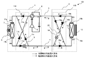
- FIG. 1 is a refrigerant circuit configuration diagram of the refrigeration cycle device according to the first embodiment of the present invention.
- the outdoor unit 1 and the indoor unit 2 are connected by a gas pipe 3 and a liquid pipe 4 to form one refrigerant circuit.
- R407C which is a mixed refrigerant of three types of HFC refrigerants having different boiling points
- the enclosed refrigerant is not limited to this, and may be, for example, a mixed refrigerant of R1234yf and R32, which are HFO refrigerants.
- an HC refrigerant such as R290 or a mixed refrigerant containing a natural refrigerant such as CO2 as one of the components may be adopted.
- the outdoor unit 1 contains a compressor 5, a four-way valve 6, an outdoor heat exchanger 7, an outdoor blower 8, and an outdoor bridge circuit 10 whose operating capacity can be adjusted.
- An outdoor inlet header 17a and an outdoor outlet header 17b are installed in front of and behind the outdoor heat exchanger 7, and the other end of each header is connected to the outdoor bridge circuit 10.
- the outdoor blower 8 provided attached to the outdoor heat exchanger 7 adjusts the amount of heat exchange between the refrigerant and the outdoor air by changing the amount of air blown to the outdoor heat exchanger 7.
- the outdoor bridge circuit 10 is provided with four entrances and exits, one end of the outdoor inlet header 17a and one end of the outdoor outlet header 17b, one end of the four-way valve 6 and the connection end of the liquid pipe 4, and three check valves. It is composed of valves 11a, 11b, 11c and an outdoor expansion valve 9.
- the outdoor expansion valve 9 is configured so that the valve body can be moved by a pulse motor or the like, and the opening degree can be continuously adjusted from a completely closed state to a fully open state.
- the outdoor bridge circuit 10 has a refrigerant flow path so that the refrigerant flows toward the indoor inlet header 17a regardless of whether the cooling operation is such that the refrigerant flows in from the four-way valve 6 or the heating operation in which the refrigerant flows from the liquid pipe 4. Is configured.
- the indoor unit 2 contains an indoor heat exchanger 12, an indoor blower 13 for adjusting the amount of heat exchange between the refrigerant flowing through the indoor heat exchanger 12 and the indoor air, and an indoor bridge circuit 15. Further, an indoor inlet header 18a and an indoor outlet header 18b are installed at both ends of the indoor heat exchanger 12, and the other end side of each header is connected to the indoor bridge circuit 15.
- the indoor bridge circuit 15 includes three check valves 16a, 16b, 16c and an indoor expansion valve 14. Like the outdoor expansion valve 9, the indoor expansion valve 14 can continuously adjust the opening degree from a completely closed state to a fully open state.
- the refrigerant flow path is such that the refrigerant flow path flows from the indoor inlet header 18a side to the indoor heat exchanger 12 in both the cooling operation in which the refrigerant flows in from the liquid pipe 4 and the heating operation in which the refrigerant flows in from the gas pipe 3. It is configured.
- FIG. 2 is a schematic diagram showing the relationship between the refrigerant flow path of the outdoor heat exchanger 7 and the air flow direction.
- the outdoor heat exchanger 7 is composed of a plurality of heat transfer tubes 19 and a plurality of laminated fins 20.
- the heat transfer tube 19 is a copper circular tube, and in the present embodiment, it is arranged in 6 stages in the vertical direction and 4 rows in the air flow direction.
- the fins 20 are thin aluminum plates having a thickness of about 0.1 mm, and are laminated at intervals of 1 to 2 mm.
- the refrigerant flowing into the outdoor heat exchanger 7 is branched into three at the outdoor inlet header 17a, flows into the outdoor heat exchanger 7, travels in the row direction while reciprocating in the stacking direction of the fins 20, and merges at the outdoor outlet header 17b. do.
- the flow of outdoor air generated by the outdoor blower 8 (not shown) is from right to left on the paper surface, the air and the refrigerant become so-called countercurrents in which heat exchange occurs between the inlet side and the outlet side, respectively.
- This configuration is the same for the indoor heat exchanger 12, and is configured such that the refrigerant inlet and the air outlet and the refrigerant outlet and the air inlet are in thermal contact. Subsequently, the refrigerant control during the cooling operation and the heating operation will be described.
- the four-way valve 6 shown in FIG. 1 has an internal flow path set in the solid line direction.
- the refrigerant discharged from the compressor 5 flows into the outdoor bridge circuit 10 via the four-way valve 6.
- the refrigerant flowing into the outdoor bridge circuit 10 passes through the check valve 11a and flows into the indoor heat exchanger 12 from the inlet header 17a side.
- the check valve 11b is closed due to the high pressure on the outlet side.
- the refrigerant radiated to the outdoor air by the indoor heat exchanger 12 and condensed and liquefied passes through the outdoor outlet header 17b, flows into the outdoor bridge circuit 10 again, is depressurized by the outdoor expansion valve 9, and becomes a low-pressure two-phase refrigerant.
- the opening degree of the outdoor expansion valve is controlled so that the temperature of the discharged gas refrigerant of the compressor 5 becomes a target value, for example.
- the low-pressure two-phase state refrigerant that has flowed out of the outdoor unit 1 flows into the indoor unit 2 through the liquid pipe 4.
- the refrigerant flows into the indoor bridge circuit 15, passes through the check valve 16c, and flows into the indoor heat exchanger 12 from the indoor inlet header 18a side.
- the indoor expansion valve 14 is closed so that the refrigerant does not flow.
- the refrigerant that has flowed into the indoor heat exchanger 12 is heated by the indoor air and evaporates, becomes a low-pressure gas refrigerant, and flows out from the indoor outlet header 18b.
- the refrigerant flowing out of the indoor heat exchanger 12 flows into the indoor bridge circuit 15 again, passes through the check valve 16b, and flows out of the indoor unit 2.
- the refrigerant flowing out of the indoor unit 2 flows through the gas pipe 3 and returns to the outdoor unit 1 again, and is sucked into the compressor 5 via the four-way valve 6. In this way, the non-azeotropic refrigerant enclosed in the refrigeration cycle apparatus 100 circulates in the refrigerant circuit to perform cooling operation.
- the refrigerant condensed in the outdoor heat exchanger 7 is depressurized by the outdoor expansion valve 9, so that the refrigerant flowing through the liquid pipe 4 is a low-pressure two-phase refrigerant.
- the low-pressure two-phase refrigerant has a relatively low temperature, and when it comes into contact with the outdoor air, the moisture in the air may condense. Since the density is smaller than that of the above, the amount of the refrigerant enclosed in the refrigerant circuit can be reduced.
- FIG. 3 is a graph showing an example of a temperature change from the inflow of the refrigerant and air into the condenser to the outflow
- FIG. 4 is a graph showing the temperature change from the inflow of the refrigerant and air into the evaporator to the outflow. It is a graph which shows an example.
- the vertical axis represents temperature
- the horizontal axis represents the relative position of the path from the heat exchanger inlet to the outlet of each of the refrigerant and air. Since the condenser and the evaporator shown in FIGS.
- the refrigerant flows from the left end A to the right end B on the horizontal axis, and the air flows from the right end B to the left end A. .. Further, the section C on the horizontal axis indicates that the refrigerant is in a gas-liquid two-phase state.
- FIG. 3 shows the temperature changes of the refrigerant and air inside the outdoor heat exchanger 7 that operates as a condenser during the cooling operation in this embodiment.
- the refrigerant flowing through the outdoor heat exchanger 7 flows in in a high temperature gas state of about 70 ° C., is cooled by air, and liquefaction starts at around 50 ° C. Since the refrigerant is a non-azeotropic mixed refrigerant, the temperature gradually decreases even in the section C in the two-phase state, and the temperature further decreases even after the complete liquefaction.
- the refrigerant is cooled to a temperature close to the air inlet temperature of 35 ° C.
- the air that has become sufficiently hot on the air outlet side exchanges heat with the high temperature gas refrigerant on the refrigerant inlet side, and the supercooled liquid refrigerant on the refrigerant outlet side and the air inlet side. Since heat is exchanged with the outdoor air, a sufficient temperature difference with the air is secured even after the refrigerant changes from the gas-liquid two-phase state to the liquid single-phase state, and heat exchange can be performed with high efficiency.
- FIG. 4 shows the temperature change of the indoor heat exchanger 12, which serves as an evaporator during the cooling operation, in this embodiment.
- the refrigerant flowing into the indoor heat exchanger 12 is in a low-pressure two-phase state of about 10 ° C. at the refrigerant inlet A, gradually rises in temperature while exchanging heat with the indoor air, and flows out of the section C indicating the two-phase state. do. After that, heat is further exchanged with the indoor air, and the refrigerant outlet B flows out in a low pressure gas state having a predetermined degree of superheat.
- the air has a temperature of about 27 ° C., which is the room temperature at the air inlet B, and is cooled by the refrigerant to become low temperature air of about 15 ° C. at the air outlet A. Cooling operation is performed when this low temperature air is blown into the room.
- the four-way valve 6 shown in FIG. 1 has an internal flow path set in the direction of the broken line.
- the refrigerant discharged from the compressor 5 flows out of the outdoor unit 1 via the four-way valve 6.
- the refrigerant flowing out of the outdoor unit 1 flows into the indoor unit 2 via the gas pipe 3, and first flows into the indoor bridge circuit 15.
- the refrigerant passes through the check valve 16a, flows out of the indoor bridge circuit, and flows into the indoor heat exchanger 12 from the indoor inlet header 18a side.
- the check valve 16b is closed due to the high pressure on the outlet side.
- the refrigerant dissipates heat to the indoor air to be condensed and liquefied, and flows out of the indoor heat exchanger 12 from the indoor outlet header 18b.
- the refrigerant flowing out of the indoor heat exchanger 12 flows into the indoor bridge circuit 15 again, is depressurized by the indoor expansion valve 14, and becomes a low-pressure two-phase state.
- the low-pressure two-phase refrigerant flows out of the indoor unit 2 and flows into the outdoor unit 1 via the liquid pipe 4.
- the refrigerant passes through the check valve 11c provided in the outdoor bridge circuit 10 and flows into the outdoor heat exchanger 7 from the outdoor inlet header 17a side.
- the refrigerant is heated by the outdoor air to be in a low pressure gas state, and flows into the outdoor bridge circuit 10 again via the outdoor outlet header 17b.
- the outdoor expansion valve 9 is closed, and the refrigerant flows out of the outdoor bridge circuit 10 through the check valve 11b.
- the refrigerant is subsequently sucked into the compressor 5 again via the four-way valve 6.
- the refrigerant flowing through the outdoor heat exchanger 7 and the indoor heat exchanger 12 flows countercurrent with air in both the cooling operation and the heating operation. To form.
- the air and the refrigerant can efficiently exchange heat by ensuring a sufficient temperature difference from the inlet to the outlet of the heat exchanger, and the performance of the refrigeration cycle apparatus is improved. This effect is remarkable when a non-azeotropic mixed refrigerant is used.
- the bridge circuit is housed in both the outdoor unit 1 and the indoor unit 2.
- the heat exchange efficiency on the side provided with the bridge circuit is improved and the refrigeration cycle is provided. The effect of improving the performance of the device can be obtained.
- the refrigerant flowing through the liquid pipe 4 is in a low pressure two-phase state in both the cooling operation and the heating operation, and the liquid pipe 4 is filled with the liquid refrigerant. Therefore, the amount of refrigerant sealed in the refrigerant circuit can be reduced.
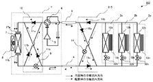
- FIG. 5 is a refrigerant circuit configuration diagram of the refrigerating cycle device 101 according to the second embodiment of the present invention.
- the check valve 11d is installed in the flow path in which the outdoor expansion valve 9 of the outdoor bridge circuit 110 is arranged.
- a check valve 16d and a rectifier 20 are installed on the upstream side of the indoor expansion valve 14 in the flow path in which the indoor expansion valve 14 of the indoor bridge circuit 115 is arranged.
- the check valve 11d is a flow path provided with an outdoor expansion valve 9 so that the refrigerant flowing from the liquid pipe 4 to the outdoor unit 1 during the heating operation does not flow to the outlet side of the indoor heat exchanger 12. Is mechanically shut off. As a result, the refrigerant circuit during the heating operation is formed without completely closing the outdoor expansion valve 9 during the heating operation.
- the operation of completely closing the expansion valve often involves an operation in which the valve body and the valve seat collide with each other many times, wear of the expansion valve is promoted especially under operating conditions in which cooling and heating are alternately repeated.
- the number of times of controlling the opening degree of the outdoor expansion valve 9 is reduced, and the aged deterioration of the outdoor expansion valve 9 can be suppressed.
- the check valve 16d mechanically blocks the flow of the refrigerant from the liquid pipe 4 to the outlet side of the indoor heat exchanger 12 during the cooling operation, whereby the outdoor expansion valve is used during the cooling operation. It is no longer necessary to completely close the 14. As a result, the number of times the opening degree of the indoor expansion valve 14 is controlled is reduced, and the aged deterioration of the indoor expansion valve 14 can be suppressed.
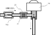
- FIG. 6 is a cross-sectional view showing a flow path configuration including an indoor expansion valve 14 in the indoor bridge circuit 115.
- the rectifier 20 includes a rectifying unit 21 made of a metal mesh or foamed metal inside.
- the rectifier 20 is homogeneous in the rectifying unit 21 even in a situation where bubbles flow discontinuously at the inlet of the expansion valve 14, such as when the refrigerating cycle device 100 has an unstable refrigerant distribution immediately after the start of heating operation. Convert to a bubble flow.
- irregular vibration or refrigerant flow noise does not occur in the indoor expansion valve 14, and the comfort of the indoor environment is not impaired by the noise from the refrigeration cycle device.
- the same effect as that of the refrigerating cycle device 100 according to the first embodiment can be obtained. Further, since the check valve 11d and the check valve 16d are provided, the number of times the opening degree of the outdoor expansion valve 9 and the indoor expansion valve 14 is controlled is reduced, and the aged deterioration of the expansion valve can be suppressed. Further, since the rectifier 20 is provided, it is possible to provide a comfortable air-conditioning environment without generating a refrigerant flow noise or irregular vibration in the room.
- FIG. 7 is a refrigerant circuit configuration diagram of the refrigerating cycle device 102 according to the third embodiment of the present invention.
- the refrigerating cycle device 102 is independently deployed with respect to the refrigerating cycle device 100 according to the first embodiment, in which the indoor bridge circuit 215 is not built in the indoor unit 2. Further, the indoor units 2a, 2b, and 2c are connected in parallel to the indoor bridge circuit 215, respectively, and the on-off valves 22a, 22b, which can shut off the flow of the refrigerant to the refrigerant inlet side of the indoor heat exchangers 12a, 12b, 12c, It is equipped with 22c.
- the refrigeration cycle device 102 is an air conditioner for multiple rooms, and the indoor units 2a, 2b, and 2c control the air temperature of each of the installed rooms. At this time, if each of the indoor units 2a, 2b, and 2c is provided with the indoor bridge circuit 15 as in the first embodiment or the second embodiment, the air conditioning capacity cannot be adjusted for each room during the cooling operation. .. Therefore, if there is an imbalance in the air conditioning load between the rooms, excess or deficiency of the air conditioning capacity will occur.
- the refrigeration cycle device 102 includes on-off valves 22a, 22b, and 22c for each indoor unit, the on-off valve is temporarily turned on when the air conditioning capacity of a specific room becomes excessive during cooling operation or heating operation. By closing it, it is possible to prevent the room from exerting its air-conditioning capacity. As a result, even when a plurality of indoor units are connected, the air conditioning capacity can be controlled independently for each indoor unit, and a comfortable air conditioning environment can be provided.
- the refrigeration cycle device 102 is configured to connect a plurality of indoor units to one indoor bridge circuit 215, the number of parts such as check valves constituting the bridge circuit is reduced, and the manufacturing cost is reduced. Will be done.
- the refrigerating cycle device 102 even when a plurality of indoor units are connected as an air conditioner for multiple rooms, the refrigerating cycle device 100 according to the first embodiment is used.
- a similar effect can be achieved. That is, the outdoor heat exchanger 7 and the indoor heat exchangers 12a, 12b, and 12c can be countercurrent for both cooling and heating, and the refrigerant flowing through the liquid pipe 4 can be a two-phase refrigerant having a low density for both cooling and heating.
- the air conditioning capacity can be adjusted for each indoor unit, a comfortable air conditioning environment can be provided even when the air conditioning load is unbalanced between the rooms.
- the refrigerant circuit is configured by one indoor bridge circuit 215 for the plurality of indoor units 2a, 2b, and 2c, the number of parts such as the check valve constituting the refrigerant circuit is reduced, and the manufacturing cost is reduced. Can be reduced.
- FIG. 8 is a refrigerant circuit configuration diagram of the refrigerating cycle device 103 according to the fourth embodiment of the present invention.
- the refrigeration cycle device 103 has an expansion means built in the indoor bridge circuit 315 as a mechanical fixed throttle 31 such as a capillary tube.
- the outdoor expansion valve 9 is not built in the outdoor bridge circuit 10, but is arranged between one end of the outdoor bridge circuit 10 and the liquid pipe 4.
- the fixed throttle 31 arranged in series with the flow path of the check valve 16d flows to the extent that the high-pressure liquid refrigerant flowing out of the indoor heat exchanger 12 is depressurized to a gas-liquid two-phase state during the heating operation. Designed for resistance.
- the refrigerant in the gas-liquid two-phase state in the fixed throttle 31 flows into the outdoor unit 1 via the liquid pipe 4.
- the refrigerant that has flowed into the outdoor unit 1 flows into the outdoor bridge circuit 310 after being further depressurized by the outdoor expansion valve 9.
- the opening degree of the outdoor expansion valve 9 is controlled so that the discharge gas temperature of the compressor 5, for example, becomes a target value. That is, in the refrigerating cycle device 103 according to the fourth embodiment, first, the refrigerant flowing through the liquid pipe 4 is depressurized to a two-phase state by the fixed throttle 31 arranged in the outdoor bridge circuit 315, and further appropriately by the outdoor expansion valve 9. Reduce the pressure to the maximum.
- the indoor bridge circuit 315 is composed only of the check valves 16a, 16b, 16c, 16d and the fixed throttle 31, it does not require a power supply and a signal for opening degree control. Therefore, since it is not necessary to connect the electric wiring to the indoor bridge circuit 315, the restrictions on the installation location are reduced and the installation work is simplified.
- the refrigerant flow rate can be controlled if only the outdoor unit 1 is equipped with the expansion valve control device, and the cost of parts such as electric circuits is reduced. can do.
- the refrigerating cycle apparatus 103 according to the fourth embodiment can exert the same effect as the refrigerating cycle apparatus 100 according to the first embodiment. That is, the outdoor heat exchanger 7 and the indoor heat exchanger 12 can be countercurrent for both cooling and heating, and the refrigerant flowing through the liquid pipe 4 can be a two-phase refrigerant having a low density for both cooling and heating.
- the indoor bridge circuit 315 is composed of only mechanical parts, electrical wiring becomes unnecessary and the installation work cost can be reduced.
- the refrigerant flow rate is adjusted by controlling the opening degree of the outdoor expansion valve 9 in both the cooling operation and the heating operation, it is not necessary to provide an expansion valve drive circuit on the indoor side, and the cost of electric parts can be reduced.
- the configuration shown in the above-described embodiment shows an example of the content of the present invention, can be combined with another known technique, and is configured without departing from the gist of the present invention. It is also possible to omit or change a part of.
Landscapes
- Engineering & Computer Science (AREA)
- Physics & Mathematics (AREA)
- Mechanical Engineering (AREA)
- Thermal Sciences (AREA)
- General Engineering & Computer Science (AREA)
- Compression-Type Refrigeration Machines With Reversible Cycles (AREA)
Abstract
冷房の場合も暖房の場合も空気と冷媒が対向流となるように冷媒流路を構成するとともに、液管に低圧二相冷媒が流通するようにすることで必要冷媒量を低減できる冷凍サイクル装置を得る。圧縮機5、冷房運転と暖房運転を切り替える四方弁6、室外熱交換器7、室外膨張弁9を備えた室外ユニット1と、室内熱交換器12、室内膨張弁14を備えた室内ユニット2と、室外ユニット1と室内ユニット2とを接続するガス管3及び液管4と、複数の流路開閉手段11を用いて室外熱交換器7を流通する冷媒の流れが冷房運転、暖房運転の双方で同一方向となるように構成された第1のブリッジ回路10と、複数の流路開閉手段16を用いて室内熱交換器12を流通する冷媒の流れが冷房運転、記暖房運転の双方で同一方向になるように構成された第2のブリッジ回路15とのうち、少なくともいずれか一方を備えた。
Description
本発明は、空気調和を行う冷凍サイクル装置に係り、特に、冷房運転と暖房運転とを切替可能に構成された冷凍サイクル装置に関する。
現在の空気調和を行う冷凍サイクル装置の多くは、冷媒の流れ方向を切り替えることで、冷房運転と暖房運転とを選択できるように構成されている。
また近年、冷凍サイクル装置に封入される冷媒の地球温暖化係数(Global Warming Performance、GWP)を低減するため、沸点が異なる複数の冷媒を混合した非共沸混合冷媒の適用が検討されている。
非共沸混合冷媒は、凝縮過程および蒸発過程で飽和温度が変化する特性を有している。そのため、空気と冷媒とを熱交換させる熱交換器においては、空気の入口側と冷媒の出口側が熱交換するように、また、冷媒入口側と空気出口側が熱交換するように空気と冷媒の流れ方向を設計する。すなわち、熱交換器全体で空気と冷媒との温度差を確保しやすい対向流となるように設計する。
しかし、冷房運転と暖房運転で冷媒の流れ方向を切り替える冷凍サイクル装置においては、冷房又は暖房いずれかの流れ方向を選択した場合に冷媒と空気が並行流となり、熱交換器の性能が低下してしまう。
このような問題を回避するため、複数の逆止弁を用いたブリッジ回路を採用することで、冷房と暖房で熱交換器の冷媒入口と冷媒出口が反転しないようにし、冷房でも暖房でも冷媒と空気が対向流とする方法が知られている(例えば、特許文献1)。
しかしながら、先行技術文献のように構成された冷凍サイクル装置では、室外熱交換器と室内熱交換器との間の液管に、冷房運転においても暖房運転においても凝縮液化した高圧冷媒が流通するため、必要冷媒量が増大するという問題が生じる。
また、冷房運転が選択されたときは室内側の膨張弁を、暖房運転が選択されたときは室外側の膨張弁を完全に閉止する必要があるため、膨張弁の開閉動作が頻繁となり、耐久性が悪化するという問題が生じる。
また、冷房運転が選択されたときは室内側の膨張弁を、暖房運転が選択されたときは室外側の膨張弁を完全に閉止する必要があるため、膨張弁の開閉動作が頻繁となり、耐久性が悪化するという問題が生じる。
この発明は、上記のような課題を解決するためになされたもので、冷房の場合も暖房の場合も室外熱交換器、室内熱交換器の少なくともいずれか一方が対向流となるように構成するとともに、必要冷媒量を低減できる冷凍サイクル装置を得るものである。
上記の目的を達成するため、この発明に係る冷凍サイクル装置は、
圧縮機、冷房運転と暖房運転を切り替える四方弁、室外熱交換器、室外膨張弁を備えた室外ユニットと、
室内熱交換器、室内膨張弁を備えた室内ユニットと、
室外ユニットと室内ユニットとを接続することで非共沸混合冷媒が封入される冷媒回路を形成するガス管及び液管と、を備えた冷凍サイクル装置であって、
室外ユニットに収容され、複数の流路開閉手段を用いて室外熱交換器を流通する非共沸混合冷媒の流れが冷房運転、暖房運転の双方で同一方向となるように構成され、室外熱交換器の出口側と液管とを接続する流路に設置された流路開閉手段が室外膨張弁である第1のブリッジ回路と、
複数の流路開閉手段を用いて室内熱交換器を流通する非共沸混合冷媒の流れが冷房運転、記暖房運転の双方で同一方向になるように構成され、室内熱交換器の出口側と液管とを接続する流路に設置された流路開閉手段が室内膨張弁である第2のブリッジ回路とのうち、
少なくともいずれか一方を備えた。
本開示に係る冷凍サイクル装置は、第1のブリッジ回路及び第2のブリッジ回路によって冷房暖房の双方で室外熱交換器および室内熱交換器を対向流にすることができるので、非共沸混合冷媒が適用されても、空気と冷媒は熱交換器の入口から出口まで十分に温度差が確保されることで効率的に熱交換を行うことができ、冷凍サイクル装置の性能が向上する。
液管を流通する冷媒は、冷房運転の場合も暖房運転の場合も低圧二相状態となり、液管が液冷媒で満たされる運転状態がなくなるので、冷媒回路内に封入する冷媒量を低減することができる。
以下に、本開示の実施の形態に係る冷凍サイクル装置を図面に基づいて詳細に説明する。なお、以下の図面において同一または相当する部分には同一の符号を付し、その説明は繰返さないこととする。
実施の形態1.
<冷凍サイクル装置の構成>
図1は、本発明の実施の形態1に係る冷凍サイクル装置の冷媒回路構成図である。図1に示すように、冷凍サイクル装置100は、室外ユニット1と室内ユニット2が、ガス管3、液管4によって接続されてひとつの冷媒回路を形成している。この冷媒回路には、沸点が異なる3種類のHFC冷媒の混合冷媒であるR407Cが封入されている。封入される冷媒はこれに限定されるものではなく、例えばHFO冷媒であるR1234yfとR32との混合冷媒であってもよい。また、R290等のHC冷媒、あるいはCO2等の自然冷媒を成分の1つとする混合冷媒を採用してもよい。
<冷凍サイクル装置の構成>
図1は、本発明の実施の形態1に係る冷凍サイクル装置の冷媒回路構成図である。図1に示すように、冷凍サイクル装置100は、室外ユニット1と室内ユニット2が、ガス管3、液管4によって接続されてひとつの冷媒回路を形成している。この冷媒回路には、沸点が異なる3種類のHFC冷媒の混合冷媒であるR407Cが封入されている。封入される冷媒はこれに限定されるものではなく、例えばHFO冷媒であるR1234yfとR32との混合冷媒であってもよい。また、R290等のHC冷媒、あるいはCO2等の自然冷媒を成分の1つとする混合冷媒を採用してもよい。
室外ユニット1には、運転容量を調整可能な圧縮機5、四方弁6、室外熱交換器7、室外送風機8、室外ブリッジ回路10が内蔵されている。室外熱交換器7の前後には室外入口ヘッダ17aと室外出口ヘッダ17bが設置され、それぞれのヘッダの他端側が室外ブリッジ回路10に接続されている。室外熱交換器7に付随して設けられた室外送風機8は、室外熱交換器7への送風量を変化させることで、冷媒と室外空気との熱交換量を調整する。
室外ブリッジ回路10は、前述した室外入口ヘッダ17aの一端と室外出口ヘッダ17bの一端、さらに四方弁6の一端と液管4との接続端と、併せて4つの出入口を備え、3つの逆止弁11a、11b、11cと室外膨張弁9で構成されている。室外膨張弁9は、パルスモータ等で弁体が移動可能に構成され、完全に閉止した状態から全開まで連続的に開度調節可能となっている。室外ブリッジ回路10は、四方弁6から冷媒が流入する冷房運転の場合でも、液管4から冷媒が流入する暖房運転の場合でも、室内入口ヘッダ17aに向かって冷媒が流出するように冷媒流路が構成されている。
室内ユニット2には、室内熱交換器12と、室内熱交換器12を流通する冷媒と室内空気との熱交換量を調整するための室内送風機13、室内ブリッジ回路15が内蔵されている。また、室内熱交換器12の両端には室内入口ヘッダ18aと室内出口ヘッダ18bが設置されており、それぞれのヘッダの他端側は室内ブリッジ回路15に接続されている。
室内ブリッジ回路15は、3つの逆止弁16a、16b、16cと室内膨張弁14を備えている。室内膨張弁14は、室外膨張弁9と同様に、完全に閉止した状態から全開まで連続的に開度調節可能となっている。室内ブリッジ回路15は、冷媒が液管4から流入する冷房運転の場合でもガス管3から流入する暖房運転の場合でも室内入口ヘッダ18a側から室内熱交換器12を流通するように冷媒流路が構成されている。
図2は、室外熱交換器7の冷媒流通経路と空気の流れ方向との関係を示す模式図である。室外熱交換器7は、複数の伝熱管19と複数枚積層されたフィン20で構成されている。伝熱管19は銅製の円管であり、本実施の形態では鉛直方向に6段、空気流れ方向に4列の配列となっている。フィン20は厚さ0.1mm程度のアルミニウム製の薄板であり、1~2mmの間隔を空けて積層されている。
室外熱交換器7に流入する冷媒は、室外入口ヘッダ17aで3分岐されて室外熱交換器7に流入し、フィン20の積層方向に往復しながら列方向に進行し、室外出口ヘッダ17bで合流する。一方、図示していない室外送風機8によって生成される室外空気の流れは、紙面の右から左であるので、空気と冷媒はそれぞれの入口側と出口側が熱交換を行う、いわゆる対向流となっている。この構成は、室内熱交換器12でも同様であり、冷媒入口と空気出口、冷媒出口と空気入口が熱的に接触するように構成されている。続いて、冷房運転時及び暖房運転時の冷媒制御について説明する。
<冷房運転>
冷房運転時、図1に図示された四方弁6は、実線方向に内部流路が設定される。圧縮機5を吐出した冷媒は、四方弁6を経由して室外ブリッジ回路10に流入する。室外ブリッジ回路10に流入した冷媒は逆止弁11aを通過し、入口ヘッダ17a側から室内熱交換器12に流入する。このとき逆止弁11bは、出口側が高圧となることにより閉止する。室内熱交換器12で室外空気に放熱し、凝縮液化した冷媒は、室外出口ヘッダ17bを通過して再び室外ブリッジ回路10に流入し、室外膨張弁9で減圧されて低圧二相冷媒となる。室外膨張弁の開度は、例えば圧縮機5の吐出ガス冷媒の温度が目標値になるように制御される。
冷房運転時、図1に図示された四方弁6は、実線方向に内部流路が設定される。圧縮機5を吐出した冷媒は、四方弁6を経由して室外ブリッジ回路10に流入する。室外ブリッジ回路10に流入した冷媒は逆止弁11aを通過し、入口ヘッダ17a側から室内熱交換器12に流入する。このとき逆止弁11bは、出口側が高圧となることにより閉止する。室内熱交換器12で室外空気に放熱し、凝縮液化した冷媒は、室外出口ヘッダ17bを通過して再び室外ブリッジ回路10に流入し、室外膨張弁9で減圧されて低圧二相冷媒となる。室外膨張弁の開度は、例えば圧縮機5の吐出ガス冷媒の温度が目標値になるように制御される。
室外ユニット1を流出した低圧二相状態の冷媒は、液管4を通って室内ユニット2に流入する。室内ユニット2では、冷媒は室内ブリッジ回路15に流入し、逆止弁16cを通過して室内入口ヘッダ18a側から室内熱交換器12に流入する。このとき、室内膨張弁14は冷媒が流通しないように閉止されている。
室内熱交換器12に流入した冷媒は、室内空気によって加熱されて蒸発し、低圧ガス冷媒となって室内出口ヘッダ18bから流出する。室内熱交換器12を流出した冷媒は、再び室内ブリッジ回路15に流入し、逆止弁16bを通過して室内ユニット2を流出する。
室内ユニット2を流出した冷媒は、ガス管3を流通して再び室外ユニット1に戻り、四方弁6を経由して圧縮機5に吸入される。このように、冷凍サイクル装置100に封入された非共沸冷媒は、冷媒回路内を循環して冷房運転を行う。
上記で説明したように、冷房運転では、室外熱交換器7で凝縮した冷媒は室外膨張弁9によって減圧されるので、液管4を流通する冷媒は低圧二相冷媒である。低圧二相冷媒は比較的低温であり、室外空気に触れると空気中の水分が結露する可能性があるため、十分に断熱する必要がある一方で、室外熱交換器7で凝縮した高圧液冷媒よりも密度が小さいので、冷媒回路に封入される冷媒量を低減することができる。
図3は、冷媒と空気が凝縮器に流入してから流出するまでの温度変化の一例を示すグラフであり、図4は、冷媒と空気が蒸発器に流入してから流出するまでの温度変化の一例を示すグラフである。図3および図4において、縦軸は温度であり、横軸は冷媒と空気それぞれの熱交換器入口から出口に至る経路の相対位置を表している。図3および図4に示す凝縮器及び蒸発器は対向流で構成されているので、横軸の左端Aから右端Bに向けて冷媒が流通し、空気は右端Bから左端Aに向かって流通する。また、横軸の区間Cは、冷媒が気液二相状態となっていることを示している。
図3は、この実施の形態において、冷房運転時に凝縮器として動作する室外熱交換器7内部の冷媒と空気の温度変化を示している。室外熱交換器7に流通する冷媒は、70℃程度の高温ガス状態で流入し、空気によって冷却されて50℃付近で液化が始まる。冷媒は非共沸混合冷媒であるために、二相状態である区間Cにおいても徐々に温度が低下し、完全に液化した後もさらに温度が低下する。冷媒は、室外熱交換器7の出口側では空気入口温度である35℃に近い温度まで冷却されて過冷却度を確保した後、室外熱交換器7を流出する。一方、空気は、熱交換途中で相変化を生じないので、35℃で室外熱交換器7に流入した後、冷媒からの加熱によって単調に温度上昇する。
このように、対向流で構成された凝縮器では、空気出口側の十分高温となった空気が冷媒入口側の高温ガス冷媒と熱交換し、冷媒出口側の過冷却液冷媒と空気入口側の室外空気と熱交換するので、冷媒が気液二相状態から液単相状態になった後も空気との温度差が十分に確保され、高い効率で熱交換を行うことができる。
図4は、この実施の形態において、冷房運転時に蒸発器となる室内熱交換器12の温度変化を示している。室内熱交換器12に流入する冷媒は、冷媒入口Aでは10℃程度の低圧二相状態であり、室内の空気と熱交換を行いながら徐々に温度上昇し、二相状態を示す区間Cを流出する。その後、さらに室内空気と熱交換を行い、所定の過熱度を有する低圧ガス状態で冷媒出口Bを流出する。
一方で空気は、空気入口Bでは室温である27℃程度の温度であり、冷媒によって冷却されて空気出口Aでは15℃程度の低温空気となる。この低温空気が室内に送風されること冷房運転が行われる。
このように、対向流で構成された蒸発器では、非共沸混合冷媒の特性上、最も低温である冷媒入口と空気出口が熱交換するので、効率的に空気を冷却でき、また、冷媒出口側ではまだ高温である室内空気と冷媒が熱交換するので十分な過熱度が得られる。
<暖房運転>
暖房運転時、図1に図示された四方弁6は、破線方向に内部流路が設定される。圧縮機5を吐出した冷媒は、四方弁6を経由して室外ユニット1を流出する。室外ユニット1を流出した冷媒は、ガス管3を経由して室内ユニット2に流入し、まず室内ブリッジ回路15に流入する。室内ブリッジ回路15では、冷媒は逆止弁16aを通過して室内ブリッジ回路を流出し、室内入口ヘッダ18a側から室内熱交換器12に流入する。このとき、逆止弁16bは、出口側が高圧となることにより閉止される。
暖房運転時、図1に図示された四方弁6は、破線方向に内部流路が設定される。圧縮機5を吐出した冷媒は、四方弁6を経由して室外ユニット1を流出する。室外ユニット1を流出した冷媒は、ガス管3を経由して室内ユニット2に流入し、まず室内ブリッジ回路15に流入する。室内ブリッジ回路15では、冷媒は逆止弁16aを通過して室内ブリッジ回路を流出し、室内入口ヘッダ18a側から室内熱交換器12に流入する。このとき、逆止弁16bは、出口側が高圧となることにより閉止される。
室内熱交換器12では、冷媒は室内空気に放熱して凝縮液化し、室内出口ヘッダ18bから室内熱交換器12を流出する。室内熱交換器12を流出した冷媒は、再び室内ブリッジ回路15に流入し、室内膨張弁14で減圧されて低圧二相状態となる。
低圧二相状態となった冷媒は、室内ユニット2を流出し、液管4を経由して室外ユニット1に流入する。室外ユニット1では、冷媒は室外ブリッジ回路10に備えられた逆止弁11cを通過して室外入口ヘッダ17a側から室外熱交換器7に流入する。
室外熱交換器7では、冷媒は室外空気に加熱されて低圧ガス状態となり、室外出口ヘッダ17bを経由して再び室外ブリッジ回路10に流入する。このとき、室外膨張弁9は閉止されており、冷媒は逆止弁11bを通って室外ブリッジ回路10を流出する。冷媒は続いて四方弁6を経由して再び圧縮機5に吸入される。
以上のように、この実施の形態1の冷凍サイクル装置100によれば、室外熱交換器7および室内熱交換器12を流通する冷媒は、冷房運転の場合も暖房運転の場合も空気と対向流を形成する。これにより、空気と冷媒は熱交換器の入口から出口まで十分に温度差が確保されることで効率的に熱交換を行うことができ、冷凍サイクル装置の性能が向上する。この効果は、非共沸混合冷媒を用いた場合に顕著に発揮される。
なお、この実施の形態では室外ユニット1、室内ユニット2の双方にブリッジ回路を収容しているが、何れか一方に備えた場合でもブリッジ回路を備えた側の熱交換効率が向上し、冷凍サイクル装置の性能向上効果が得られる。
さらに、この実施の形態の冷凍サイクル装置によれば、液管4を流通する冷媒は、冷房運転の場合も暖房運転の場合も低圧二相状態となり、液管4が液冷媒で満たされる運転状態がなくなるので、冷媒回路内に封入する冷媒量を低減することができる。
実施の形態2.
図5は、本発明の実施の形態2に係る冷凍サイクル装置101の冷媒回路構成図である。実施の形態1に係る冷凍サイクル装置100に対して、冷凍サイクル装置101は、室外ブリッジ回路110の室外膨張弁9が配置された流路に逆止弁11dが設置されている。また、室内ブリッジ回路115の室内膨張弁14が配置された流路には、逆止弁16dと、室内膨張弁14の上流側に整流器20が設置されている。
図5は、本発明の実施の形態2に係る冷凍サイクル装置101の冷媒回路構成図である。実施の形態1に係る冷凍サイクル装置100に対して、冷凍サイクル装置101は、室外ブリッジ回路110の室外膨張弁9が配置された流路に逆止弁11dが設置されている。また、室内ブリッジ回路115の室内膨張弁14が配置された流路には、逆止弁16dと、室内膨張弁14の上流側に整流器20が設置されている。
室外ブリッジ回路110において、逆止弁11dは、暖房運転時に液管4から室外ユニット1に流入する冷媒が室内熱交換器12の出口側へ流通しないように、室外膨張弁9を備えた流路を機械的に遮断する。これにより、暖房運転時に室外膨張弁9を完全に閉止することなく暖房運転時の冷媒回路が形成される。
膨張弁の完全閉止動作は、弁体と弁座が何度も衝突する動作を伴うケースが多いので、特に冷房と暖房を交互に繰り返すような運転条件では膨張弁の摩耗を促進してしまう。この実施の形態によれば、室外膨張弁9の開度制御回数が減少し、室外膨張弁9の経年劣化を抑制することができる。
室内ブリッジ回路115についても同様であり、逆止弁16dが、冷房運転時に液管4から室内熱交換器12の出口側への冷媒流通を機械的に阻止することにより、冷房運転時に室外膨張弁14を完全に閉止する必要がなくなる。これにより、室内膨張弁14の開度制御回数が低減され、室内膨張弁14の経年劣化を抑制することができる。
図6は、室内ブリッジ回路115における室内膨張弁14を備えた流路構成を示す断面図である。整流器20は、内部に金属メッシュあるいは発泡金属で構成された整流部21を備えている。整流器20は、冷凍サイクル装置100が暖房運転開始直後で冷媒分布が安定していない場合など、膨張弁14の入口に不連続に気泡が流通するような状況であっても、整流部21で均質な気泡流に変換する。これにより、室内膨張弁14に不規則な振動あるいは冷媒流動音が生じることがなく、冷凍サイクル装置からの騒音によって室内環境の快適性が損なわれることが無い。
以上のように、実施の形態2に係る冷凍サイクル装置101によれば、実施の形態1に係る冷凍サイクル装置100と同様の効果を奏することができる。さらに、逆止弁11d及び逆弁16dを備えたので、室外膨張弁9及び室内膨張弁14の開度制御回数が低減され、膨張弁の経年劣化を抑制することができる。また、整流器20を備えたので、室内に冷媒流動音や不規則な振動を発生させることがなく、快適な空調環境を提供できる。
実施の形態3.
図7は、本発明の実施の形態3に係る冷凍サイクル装置102の冷媒回路構成図である。実施の形態1に係る冷凍サイクル装置100に対して、冷凍サイクル装置102は、室内ブリッジ回路215が室内ユニット2に内蔵されず、独立して配備されている。また、室内ユニット2a、2b、2cは、室内ブリッジ回路215にそれぞれ並列に接続されており、室内熱交換器12a、12b、12cの冷媒入口側に冷媒の流通を遮断できる開閉弁22a、22b、22cを備えている。
図7は、本発明の実施の形態3に係る冷凍サイクル装置102の冷媒回路構成図である。実施の形態1に係る冷凍サイクル装置100に対して、冷凍サイクル装置102は、室内ブリッジ回路215が室内ユニット2に内蔵されず、独立して配備されている。また、室内ユニット2a、2b、2cは、室内ブリッジ回路215にそれぞれ並列に接続されており、室内熱交換器12a、12b、12cの冷媒入口側に冷媒の流通を遮断できる開閉弁22a、22b、22cを備えている。
冷凍サイクル装置102は多室用の空気調和装置であり、室内ユニット2a、2b、2cは設置されたそれぞれの部屋の空気温度制御を行う。このとき、実施の形態1あるいは実施の形態2のように、各室内ユニット2a、2b、2cがそれぞれ室内ブリッジ回路15を備えてしまうと、冷房運転時に空調能力を部屋毎に調整することができない。そのため、部屋間で空調負荷にアンバランスがある場合には空調能力の過不足を生じてしまう。
冷凍サイクル装置102は、室内ユニット毎に開閉弁22a、22b、22cを備えているため、冷房運転中あるいは暖房運転中に特定の部屋の空調能力が過剰となった場合、一時的に開閉弁を閉止することでその部屋の空調能力を発揮しないようにすることができる。これにより、室内ユニットが複数接続された場合であっても、室内ユニット毎に独立に空調能力制御が可能となり、快適な空調環境を提供できる。
また、冷凍サイクル装置102は、1台の室内ブリッジ回路215に複数の室内ユニットが接続される構成となっているので、ブリッジ回路を構成する逆止弁等の部品点数が減り、製造コストが低減される。
以上のように、実施の形態3に係る冷凍サイクル装置102によれば、多室用の空気調和装置として複数の室内ユニットが接続された場合においても、実施の形態1に係る冷凍サイクル装置100と同様の効果を奏することができる。すなわち、室外熱交換器7および室内熱交換器12a、12b、12cを冷房暖房ともに対向流とするとともに、液管4を流通する冷媒を冷房暖房ともに密度の小さい二相冷媒にすることができる。さらに、室内ユニット毎に空調能力を調整できるので、部屋間で空調負荷にアンバランスがある場合においても快適な空調環境を提供できる。
また、複数の室内ユニット2a、2b、2cに対して室内ブリッジ回路215を1台で冷媒回路を構成しているので、冷媒回路を構成する逆止弁等の部品点数が削減され、製造コストを低減することができる。
実施の形態4.
図8は、本発明の実施の形態4に係る冷凍サイクル装置103の冷媒回路構成図である。実施の形態1に係る冷凍サイクル装置100に対して、冷凍サイクル装置103は、室内ブリッジ回路315に内蔵される膨張手段を、キャピラリチューブのような機械式の固定絞り31としたものである。また、室外膨張弁9は、室外ブリッジ回路10に内蔵されず、室外ブリッジ回路10の一端と液管4との間に配置されている。
図8は、本発明の実施の形態4に係る冷凍サイクル装置103の冷媒回路構成図である。実施の形態1に係る冷凍サイクル装置100に対して、冷凍サイクル装置103は、室内ブリッジ回路315に内蔵される膨張手段を、キャピラリチューブのような機械式の固定絞り31としたものである。また、室外膨張弁9は、室外ブリッジ回路10に内蔵されず、室外ブリッジ回路10の一端と液管4との間に配置されている。
室内ブリッジ回路315において、逆止弁16dの流路に直列に配置された固定絞り31は、暖房運転時に室内熱交換器12を流出した高圧液冷媒を気液二相状態まで減圧する程度の流動抵抗に設計されている。暖房運転時、固定絞り31で気液二相状態となった冷媒は、液管4を経由して室外ユニット1に流入する。
室外ユニット1に流入した冷媒は、室外膨張弁9によってさらに減圧された後に室外ブリッジ回路310に流入する。このとき、室外膨張弁9の開度は、例えば圧縮機5の吐出ガス温度が目標値になるように制御される。すなわち、この実施の形態4に係る冷凍サイクル装置103は、まず室外ブリッジ回路315に配置された固定絞り31で液管4を流通する冷媒を二相状態まで減圧し、さらに室外膨張弁9によって適切な圧力まで減圧する。
室内ブリッジ回路315は、逆止弁16a、16b、16c、16dと固定絞り31だけで構成されるので、開度制御のための電源および信号を必要としない。そのため、室内ブリッジ回路315に電気配線を接続する必要が無いので、設置場所の制約が小さくなるとともに、設置工事作業が簡略化される。
また、冷房運転でも暖房運転でも室外膨張弁9で開度制御を行うので、室外ユニット1だけが膨張弁の制御装置を備えれば冷媒流量制御が可能であり、電気回路等の部品コストを削減することができる。
以上のように、実施の形態4に係る冷凍サイクル装置103は、実施の形態1に係る冷凍サイクル装置100と同様の効果を奏することができる。すなわち、室外熱交換器7および室内熱交換器12を冷房暖房ともに対向流とするとともに、液管4を流通する冷媒を冷房暖房ともに密度の小さい二相冷媒にすることができる。
また、室内ブリッジ回路315を機械部品だけで構成したので、電気配線が不要となり、設置工事コストを低減することができる。
また、冷房運転でも暖房運転でも室外膨張弁9の開度制御で冷媒流量調整を行うので、室内側に膨張弁駆動回路を備える必要が無く、電気部品コストを低減することができる
また、以上の実施の形態に示した構成は、本発明の内容の一例を示すものであり、別の公知の技術と組み合わせることも可能であるし、本発明の要旨を逸脱しない範囲で、構成の一部を省略、変更することも可能である。
1:室外ユニット、 2、2a、2b、2c:室内ユニット、 3:ガス管、 4:液管、 5:圧縮機、 6:四方弁、 7:室外熱交換器、 8:室外送風機、 9:室外膨張弁、10、110、310:室外ブリッジ回路、 11a、11b、11c、11d:室外逆止弁、 12、12a、12b、12c:室内熱交換器、 13、13a、13b、13c 室内送風機、 14:室内膨張弁、 15、115、215、315:室内ブリッジ回路、 16a、16b、16c、16d:室内逆止弁、 17a:室外入口ヘッダ、17b:室外出口ヘッダ、 18a:室内入口ヘッダ、 18b:室内出口ヘッダ、 20:整流器、 21:整流部、 22a、22b、22c:開閉弁、 31:固定絞り、 100、101、102、103:冷凍サイクル装置
Claims (7)
- 圧縮機、冷房運転と暖房運転を切り替える四方弁、室外熱交換器、室外膨張弁を備えた室外ユニットと、
室内熱交換器、室内膨張弁を備えた室内ユニットと、
前記室外ユニットと前記室内ユニットとを接続することで冷媒が封入される冷媒回路を形成するガス管及び液管と、を備えた冷凍サイクル装置であって、
前記室外ユニットに収容され、複数の流路開閉手段を用いて前記室外熱交換器を流通する前記冷媒の流れが前記冷房運転、前記暖房運転の双方で同一方向となるように構成され、前記室外熱交換器の出口側と前記液管とを接続する流路に設置された前記流路開閉手段が前記室外膨張弁である第1のブリッジ回路と、
複数の流路開閉手段を用いて前記室内熱交換器を流通する前記冷媒の流れが前記冷房運転、前記暖房運転の双方で同一方向になるように構成され、前記室内熱交換器の出口側と前記液管とを接続する流路に設置された前記流路開閉手段が前記室内膨張弁である第2のブリッジ回路とのうち、
少なくともいずれか一方を備えた冷凍サイクル装置。 - 前記第1のブリッジ回路は、前記室外膨張弁と直列に配置されて前記暖房運転時に前記冷媒の流通を阻止する第1の逆止弁を備えている請求項1に記載の冷凍サイクル装置。
- 前記第2のブリッジ回路は、前記室内膨張弁と直列に配置されて前記冷房運転時に前記冷媒の流通を阻止する第2の逆止弁を備えている請求項1に記載の冷凍サイクル装置。
- 前記第2のブリッジ回路は、前記室内膨張弁の上流側に前記冷媒の流動状態を均質にする整流手段を備えている請求項1~3に記載の冷凍サイクル装置。
- 圧縮機、冷房運転と暖房運転を切り替える四方弁、室外熱交換器、室外膨張弁を備えた室外ユニットと、
室内熱交換器、電磁弁を備えた複数の室内ユニットと、
前記室外ユニットに収容され、複数の流路開閉手段を用いて前記室外熱交換器を流通する前記冷媒の流れが前記冷房運転、前記暖房運転の双方で同一方向となるように構成され、前記室外熱交換器の出口側と前記液管とを接続する流路に設置された前記流路開閉手段が前記室外膨張弁である第1のブリッジ回路と、
前記複数の室内ユニットが並列に接続され、複数の流路開閉手段を用いて前記複数の室内ユニットを流通する前記冷媒の流れが前記冷房運転、前記暖房運転の双方で同一方向になるように構成され、前記複数の室内ユニットの出口側と前記液管とを接続する流路に室内膨張弁を備えた第2のブリッジ回路と、
前記室外ユニットと前記第2のブリッジ回路とを接続することで冷媒が封入される冷媒回路を形成するガス管及び液管と、
を備えた冷凍サイクル装置。 - 圧縮機、冷房運転と暖房運転を切り替える四方弁、室外熱交換器、室外膨張弁を備えた室外ユニットと、
室内熱交換器を備えた室内ユニットと、
前記室外ユニットと前記室内ユニットとを接続することで冷媒が封入される冷媒回路を形成するガス管及び液管と、を備えた冷凍サイクル装置であって、
前記室外ユニットに収容され、複数の流路開閉手段を用いて前記室外熱交換器を流通する前記冷媒の流れが前記冷房運転、前記暖房運転の双方で同一方向となるように構成された第1のブリッジ回路と、
複数の流路開閉手段を用いて前記室内ユニットを流通する前記冷媒の流れが前記冷房運転、前記暖房運転の双方で同一方向になるように構成され、前記室内ユニットの出口側と前記液管とを接続する流路に設置された前記流路開閉手段と直列に固定絞りを備えた第2のブリッジ回路と、
を備えた冷凍サイクル装置。 - 前記冷媒は、沸点が異なる2種類以上の冷媒からなる非共沸混合冷媒である請求項1~6に記載の冷凍サイクル装置。
Priority Applications (5)
| Application Number | Priority Date | Filing Date | Title |
|---|---|---|---|
| JP2022561802A JP7433470B2 (ja) | 2020-11-13 | 2020-11-13 | 冷凍サイクル装置 |
| EP20961605.1A EP4246057A4 (en) | 2020-11-13 | 2020-11-13 | REFRIGERATION CYCLE DEVICE |
| CN202080106920.5A CN116438413A (zh) | 2020-11-13 | 2020-11-13 | 制冷循环装置 |
| PCT/JP2020/042432 WO2022102077A1 (ja) | 2020-11-13 | 2020-11-13 | 冷凍サイクル装置 |
| US18/044,844 US20230358446A1 (en) | 2020-11-13 | 2020-11-13 | Refrigeration cycle device |
Applications Claiming Priority (1)
| Application Number | Priority Date | Filing Date | Title |
|---|---|---|---|
| PCT/JP2020/042432 WO2022102077A1 (ja) | 2020-11-13 | 2020-11-13 | 冷凍サイクル装置 |
Publications (1)
| Publication Number | Publication Date |
|---|---|
| WO2022102077A1 true WO2022102077A1 (ja) | 2022-05-19 |
Family
ID=81600929
Family Applications (1)
| Application Number | Title | Priority Date | Filing Date |
|---|---|---|---|
| PCT/JP2020/042432 WO2022102077A1 (ja) | 2020-11-13 | 2020-11-13 | 冷凍サイクル装置 |
Country Status (5)
| Country | Link |
|---|---|
| US (1) | US20230358446A1 (ja) |
| EP (1) | EP4246057A4 (ja) |
| JP (1) | JP7433470B2 (ja) |
| CN (1) | CN116438413A (ja) |
| WO (1) | WO2022102077A1 (ja) |
Citations (15)
| Publication number | Priority date | Publication date | Assignee | Title |
|---|---|---|---|---|
| JPS4329014Y1 (ja) * | 1964-01-06 | 1968-11-28 | ||
| JPH0367863U (ja) * | 1989-10-20 | 1991-07-03 | ||
| JPH03170753A (ja) * | 1989-11-30 | 1991-07-24 | Mitsubishi Electric Corp | 空気調和機 |
| JPH06257874A (ja) * | 1993-03-02 | 1994-09-16 | Mitsubishi Heavy Ind Ltd | ヒートポンプ式空気調和機 |
| JPH0798166A (ja) * | 1993-09-29 | 1995-04-11 | Toshiba Corp | 空気調和装置 |
| JPH07190528A (ja) * | 1993-12-24 | 1995-07-28 | Matsushita Electric Ind Co Ltd | ヒートポンプ式空気調和機 |
| JPH08334274A (ja) * | 1995-06-09 | 1996-12-17 | Matsushita Electric Ind Co Ltd | 空気調和機 |
| JPH09126574A (ja) * | 1995-10-30 | 1997-05-16 | Daikin Ind Ltd | 逆止弁ブリッジ冷媒回路 |
| JPH09178283A (ja) | 1995-12-22 | 1997-07-11 | Matsushita Electric Ind Co Ltd | 空気調和機および多室型空気調和機とその運転制御方法 |
| JPH09280680A (ja) * | 1996-04-09 | 1997-10-31 | Daikin Ind Ltd | 冷媒回路 |
| JPH1073334A (ja) * | 1996-08-28 | 1998-03-17 | Sanyo Electric Co Ltd | 冷凍装置 |
| JPH10318619A (ja) * | 1997-05-20 | 1998-12-04 | Mitsubishi Electric Corp | 冷凍サイクル装置 |
| JP2000274856A (ja) * | 1999-03-24 | 2000-10-06 | Mitsubishi Electric Corp | 空気調和機 |
| JP2003314930A (ja) * | 2002-04-19 | 2003-11-06 | Daikin Ind Ltd | 多室型空気調和機 |
| JP2006098020A (ja) * | 2004-09-30 | 2006-04-13 | Mitsubishi Heavy Ind Ltd | 空気調和機およびストレーナー |
Family Cites Families (2)
| Publication number | Priority date | Publication date | Assignee | Title |
|---|---|---|---|---|
| JP6336066B2 (ja) * | 2014-07-02 | 2018-06-06 | 三菱電機株式会社 | 空気調和装置 |
| US11820933B2 (en) * | 2017-12-18 | 2023-11-21 | Daikin Industries, Ltd. | Refrigeration cycle apparatus |
-
2020
- 2020-11-13 US US18/044,844 patent/US20230358446A1/en active Pending
- 2020-11-13 EP EP20961605.1A patent/EP4246057A4/en active Pending
- 2020-11-13 CN CN202080106920.5A patent/CN116438413A/zh active Pending
- 2020-11-13 WO PCT/JP2020/042432 patent/WO2022102077A1/ja unknown
- 2020-11-13 JP JP2022561802A patent/JP7433470B2/ja active Active
Patent Citations (15)
| Publication number | Priority date | Publication date | Assignee | Title |
|---|---|---|---|---|
| JPS4329014Y1 (ja) * | 1964-01-06 | 1968-11-28 | ||
| JPH0367863U (ja) * | 1989-10-20 | 1991-07-03 | ||
| JPH03170753A (ja) * | 1989-11-30 | 1991-07-24 | Mitsubishi Electric Corp | 空気調和機 |
| JPH06257874A (ja) * | 1993-03-02 | 1994-09-16 | Mitsubishi Heavy Ind Ltd | ヒートポンプ式空気調和機 |
| JPH0798166A (ja) * | 1993-09-29 | 1995-04-11 | Toshiba Corp | 空気調和装置 |
| JPH07190528A (ja) * | 1993-12-24 | 1995-07-28 | Matsushita Electric Ind Co Ltd | ヒートポンプ式空気調和機 |
| JPH08334274A (ja) * | 1995-06-09 | 1996-12-17 | Matsushita Electric Ind Co Ltd | 空気調和機 |
| JPH09126574A (ja) * | 1995-10-30 | 1997-05-16 | Daikin Ind Ltd | 逆止弁ブリッジ冷媒回路 |
| JPH09178283A (ja) | 1995-12-22 | 1997-07-11 | Matsushita Electric Ind Co Ltd | 空気調和機および多室型空気調和機とその運転制御方法 |
| JPH09280680A (ja) * | 1996-04-09 | 1997-10-31 | Daikin Ind Ltd | 冷媒回路 |
| JPH1073334A (ja) * | 1996-08-28 | 1998-03-17 | Sanyo Electric Co Ltd | 冷凍装置 |
| JPH10318619A (ja) * | 1997-05-20 | 1998-12-04 | Mitsubishi Electric Corp | 冷凍サイクル装置 |
| JP2000274856A (ja) * | 1999-03-24 | 2000-10-06 | Mitsubishi Electric Corp | 空気調和機 |
| JP2003314930A (ja) * | 2002-04-19 | 2003-11-06 | Daikin Ind Ltd | 多室型空気調和機 |
| JP2006098020A (ja) * | 2004-09-30 | 2006-04-13 | Mitsubishi Heavy Ind Ltd | 空気調和機およびストレーナー |
Non-Patent Citations (1)
| Title |
|---|
| See also references of EP4246057A4 |
Also Published As
| Publication number | Publication date |
|---|---|
| JP7433470B2 (ja) | 2024-02-19 |
| JPWO2022102077A1 (ja) | 2022-05-19 |
| US20230358446A1 (en) | 2023-11-09 |
| CN116438413A (zh) | 2023-07-14 |
| EP4246057A4 (en) | 2023-12-27 |
| EP4246057A1 (en) | 2023-09-20 |
Similar Documents
| Publication | Publication Date | Title |
|---|---|---|
| WO2018047330A1 (ja) | 空気調和装置 | |
| KR100758902B1 (ko) | 멀티 공기조화 시스템 및 그 제어방법 | |
| US6550273B2 (en) | Air conditioner using flammable refrigerant | |
| JP2006071174A (ja) | 冷凍装置 | |
| WO2021065913A1 (ja) | 蒸発器、およびそれを備えた冷凍サイクル装置 | |
| WO2016208042A1 (ja) | 空気調和装置 | |
| GB2579476A (en) | Heat exchange unit and refrigeration cycle device | |
| JP6576603B1 (ja) | 空気調和装置 | |
| JP2008039233A (ja) | 冷凍装置 | |
| JP6758506B2 (ja) | 空気調和装置 | |
| JP6832939B2 (ja) | 冷凍サイクル装置 | |
| JP7099046B2 (ja) | 輸送用冷凍装置 | |
| WO2022102077A1 (ja) | 冷凍サイクル装置 | |
| JP2012237518A (ja) | 空気調和機 | |
| CN113272598B (zh) | 空调机 | |
| JP6925508B2 (ja) | 熱交換器、冷凍サイクル装置および空気調和装置 | |
| JP6494916B2 (ja) | 熱交換器およびそれを用いた空気調和機 | |
| KR102509997B1 (ko) | 실외 유닛 | |
| WO2021106084A1 (ja) | 冷凍サイクル装置 | |
| JP2021055958A (ja) | 冷凍装置 | |
| JP2020201007A (ja) | 冷媒サイクルシステム | |
| KR20050043089A (ko) | 히트 펌프 | |
| JP6413692B2 (ja) | 空気調和装置 | |
| WO2022003754A1 (ja) | 冷凍サイクル装置 | |
| US20240027104A1 (en) | Refrigeration cycle apparatus |
Legal Events
| Date | Code | Title | Description |
|---|---|---|---|
| 121 | Ep: the epo has been informed by wipo that ep was designated in this application |
Ref document number: 20961605 Country of ref document: EP Kind code of ref document: A1 |
|
| ENP | Entry into the national phase |
Ref document number: 2022561802 Country of ref document: JP Kind code of ref document: A |
|
| NENP | Non-entry into the national phase |
Ref country code: DE |
|
| ENP | Entry into the national phase |
Ref document number: 2020961605 Country of ref document: EP Effective date: 20230613 |