WO2022097207A1 - 鉄道システム、運行管理装置、運行管理方法、および運行管理プログラム - Google Patents
鉄道システム、運行管理装置、運行管理方法、および運行管理プログラム Download PDFInfo
- Publication number
- WO2022097207A1 WO2022097207A1 PCT/JP2020/041225 JP2020041225W WO2022097207A1 WO 2022097207 A1 WO2022097207 A1 WO 2022097207A1 JP 2020041225 W JP2020041225 W JP 2020041225W WO 2022097207 A1 WO2022097207 A1 WO 2022097207A1
- Authority
- WO
- WIPO (PCT)
- Prior art keywords
- train
- arrival
- target
- next station
- station
- Prior art date
- Legal status (The legal status is an assumption and is not a legal conclusion. Google has not performed a legal analysis and makes no representation as to the accuracy of the status listed.)
- Ceased
Links
Images



Classifications
-
- G—PHYSICS
- G06—COMPUTING OR CALCULATING; COUNTING
- G06Q—INFORMATION AND COMMUNICATION TECHNOLOGY [ICT] SPECIALLY ADAPTED FOR ADMINISTRATIVE, COMMERCIAL, FINANCIAL, MANAGERIAL OR SUPERVISORY PURPOSES; SYSTEMS OR METHODS SPECIALLY ADAPTED FOR ADMINISTRATIVE, COMMERCIAL, FINANCIAL, MANAGERIAL OR SUPERVISORY PURPOSES, NOT OTHERWISE PROVIDED FOR
- G06Q50/00—Information and communication technology [ICT] specially adapted for implementation of business processes of specific business sectors, e.g. utilities or tourism
- G06Q50/40—Business processes related to the transportation industry
-
- B—PERFORMING OPERATIONS; TRANSPORTING
- B61—RAILWAYS
- B61L—GUIDING RAILWAY TRAFFIC; ENSURING THE SAFETY OF RAILWAY TRAFFIC
- B61L27/00—Central railway traffic control systems; Trackside control; Communication systems specially adapted therefor
- B61L27/10—Operations, e.g. scheduling or time tables
- B61L27/14—Following schedules
-
- B—PERFORMING OPERATIONS; TRANSPORTING
- B60—VEHICLES IN GENERAL
- B60L—PROPULSION OF ELECTRICALLY-PROPELLED VEHICLES; SUPPLYING ELECTRIC POWER FOR AUXILIARY EQUIPMENT OF ELECTRICALLY-PROPELLED VEHICLES; ELECTRODYNAMIC BRAKE SYSTEMS FOR VEHICLES IN GENERAL; MAGNETIC SUSPENSION OR LEVITATION FOR VEHICLES; MONITORING OPERATING VARIABLES OF ELECTRICALLY-PROPELLED VEHICLES; ELECTRIC SAFETY DEVICES FOR ELECTRICALLY-PROPELLED VEHICLES
- B60L15/00—Methods, circuits, or devices for controlling the traction-motor speed of electrically-propelled vehicles
- B60L15/40—Adaptation of control equipment on vehicle for remote actuation from a stationary place
-
- B—PERFORMING OPERATIONS; TRANSPORTING
- B61—RAILWAYS
- B61L—GUIDING RAILWAY TRAFFIC; ENSURING THE SAFETY OF RAILWAY TRAFFIC
- B61L27/00—Central railway traffic control systems; Trackside control; Communication systems specially adapted therefor
- B61L27/04—Automatic systems, e.g. controlled by train; Change-over to manual control
-
- B—PERFORMING OPERATIONS; TRANSPORTING
- B61—RAILWAYS
- B61L—GUIDING RAILWAY TRAFFIC; ENSURING THE SAFETY OF RAILWAY TRAFFIC
- B61L27/00—Central railway traffic control systems; Trackside control; Communication systems specially adapted therefor
- B61L27/10—Operations, e.g. scheduling or time tables
- B61L27/16—Trackside optimisation of vehicle or train operation
-
- B—PERFORMING OPERATIONS; TRANSPORTING
- B60—VEHICLES IN GENERAL
- B60L—PROPULSION OF ELECTRICALLY-PROPELLED VEHICLES; SUPPLYING ELECTRIC POWER FOR AUXILIARY EQUIPMENT OF ELECTRICALLY-PROPELLED VEHICLES; ELECTRODYNAMIC BRAKE SYSTEMS FOR VEHICLES IN GENERAL; MAGNETIC SUSPENSION OR LEVITATION FOR VEHICLES; MONITORING OPERATING VARIABLES OF ELECTRICALLY-PROPELLED VEHICLES; ELECTRIC SAFETY DEVICES FOR ELECTRICALLY-PROPELLED VEHICLES
- B60L2200/00—Type of vehicles
- B60L2200/26—Rail vehicles
-
- Y—GENERAL TAGGING OF NEW TECHNOLOGICAL DEVELOPMENTS; GENERAL TAGGING OF CROSS-SECTIONAL TECHNOLOGIES SPANNING OVER SEVERAL SECTIONS OF THE IPC; TECHNICAL SUBJECTS COVERED BY FORMER USPC CROSS-REFERENCE ART COLLECTIONS [XRACs] AND DIGESTS
- Y02—TECHNOLOGIES OR APPLICATIONS FOR MITIGATION OR ADAPTATION AGAINST CLIMATE CHANGE
- Y02T—CLIMATE CHANGE MITIGATION TECHNOLOGIES RELATED TO TRANSPORTATION
- Y02T90/00—Enabling technologies or technologies with a potential or indirect contribution to GHG emissions mitigation
- Y02T90/10—Technologies relating to charging of electric vehicles
- Y02T90/16—Information or communication technologies improving the operation of electric vehicles
Definitions
- This disclosure relates to a railway system equipped with an operation management device for managing train operation, an operation management device, an operation management method, and an operation management program.
- Patent Document 1 predicts the departure time from the next station of the preceding train when the departure delay from the next station occurs in the preceding train stopped at the next station, which is the station where the following train stops next.
- a predictive control technique for controlling the speed of the following train is disclosed so that the following train can be prevented from stopping between stations and can reach the next station in the shortest time from the time when the course in the hall is opened.
- the present disclosure has been made in view of the above, and obtains a railway system capable of suppressing the delay in arrival of the following train at the next station even when the arrival delay of the preceding train to the next station occurs. With the goal.
- the railway system of the present disclosure includes a plurality of trains and an operation management device.
- the operation management device manages the operation of the target train with at least one of the plurality of trains as the target train.
- the operation management device includes a calculation unit and a communication unit.
- the calculation unit calculates the target arrival time of the target train to the next station when the arrival delay of the preceding train, which is the train running in front of the target train, occurs among multiple trains, and the preceding train.
- the target arrival time of the target train to the next station is calculated.
- the communication unit transmits the information of the arrival target time calculated by the calculation unit to the target train.
- the delay of arrival of the following train to the next station can be suppressed.
- the figure which shows an example of the structure of the on-board device which the train which concerns on Embodiment 1 has.
- Diagram showing another example A flowchart showing an example of processing by the processing unit of the operation management device according to the first embodiment.
- the figure which shows an example of the structure of the on-board device which the train which concerns on Embodiment 2 has.
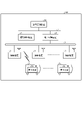
- FIG. 1 is a diagram showing an example of the configuration of the railway system according to the first embodiment.
- the railway system 100 according to the first embodiment includes a plurality of trains 2 1 to 2 m , a plurality of radio devices 3, a ground control device 4, an interlocking control device 5, and an operation management device 10.
- m is an integer of 2 or more.
- the railway system 100 is applied to, for example, a high-density line section in which the train interval in the operation schedule is about several minutes, but the application target of the railway system 100 is not limited to the high-density line section.
- the railway system 100 also called CBTC (Communications Based Train Control), is a signal for operating and controlling a plurality of trains 2 1 to 2 m by using communication between a plurality of trains 2 1 to 2 m and ground equipment. Includes security technology.
- CBTC Communication Based Train Control
- the plurality of wireless devices 3 and the ground control device 4 are connected to each other so as to be able to communicate with each other via the network 6.
- the ground control device 4, the interlocking control device 5, and the operation management device 10 are communicably connected to each other via the network 7.
- Networks 6 and 7 are intranets, but may be the Internet, or intranets and non-Internet networks.
- the wireless device 3 relays information transmitted and received between the on-board device 50 mounted on the train 2 and the ground control device 4.
- the radio device 3 receives the radio signal transmitted from the on-board device 50 of the train 2 and transmits the train state information included in the radio signal to the ground control device 4.
- the train state information includes, for example, position information indicating the position of the train 2 and speed information indicating the speed of the train 2.
- the wireless device 3 acquires the train control information to the on-board device 50 of the train 2 existing within the wireless communication range of the wireless device 3 from the ground control device 4, the wireless device 3 obtains a wireless signal including the acquired train control information. It is transmitted to the on-board device 50.
- the train control information is information for security purposes, and includes, for example, route information and stop position information of train 2.
- the route information includes information for determining the route on which the train 2 travels.
- the stop position information includes information indicating the stop limit position where the train 2 should stop, and the train 2 can travel in the route to the stop limit position.
- the stop limit position is set at the end of the route if there are no preceding trains or other obstacles in the route. If the departure course or the in-field course is not a progress indication, the stop limit position is set to a position in front of the course.
- the ground control device 4 acquires train status information from the radio device 3, and based on the acquired train status information, acquires position information indicating the current position of each train 2. Further, the ground control device 4 generates train control information for each train 2 as described later. The ground control device 4 outputs train information including train status information and train control information of each train 2 to the operation management device 10.
- the interlocking control device 5 receives the course control information output from the operation management device 10.
- the interlocking control device 5 controls a turning machine (not shown) to form a course of each train 2 based on the received course control information, or generates signal information of each train 2 and generates each train.
- the signal information of 2 is output to the ground control device 4.
- Such signal information includes information indicating a progress indication indicating a signal that gives permission to proceed to the course.
- the interlocking control device 5 generates signal information including information indicating a stop indication indicating a signal that does not give permission to proceed to the route for the route for which the route control information is not received from the operation management device 10. Output to the ground control device 4.
- the ground control device 4 generates the above-mentioned train control information for each train 2 based on the signal information transmitted from the interlocking control device 5.
- the ground control device 4 generates route information indicating a route on which the train 2 can travel, based on the train state information and signal information of the train 2. Further, the ground control device 4 generates stop position information based on the preceding train and other obstacles existing in the route, and adds the generated stop position information to the route information and the signal information to add train control information. Can be generated.
- the operation management device 10 acquires train information of each train 2 from the ground control device 4. Based on the acquired train information of each train 2 and the stored timetable information, the operation management device 10 makes each train 2 travel in the course according to the timetable information at the time according to the timetable information. Generates the course control information of train 2.
- the course control information includes, for example, train 2 information and course information.
- the operation management device 10 outputs the generated course control information of each train 2 to the interlocking control device 5.
- the operation management device 10 determines whether or not each train 2 has a delay in arriving at the next station based on the acquired position information of each train 2 and the stored timetable information. Then, the operation management device 10 sets the train 2 determined that the arrival delay to the next station has occurred as the preceding train, and the train following the preceding train as the target train for the arrival time adjustment. In the following, the train following the preceding train that has a delay in arriving at the next station will be referred to as the target train or the following train.
- the operation management device 10 determines that a delay in arrival at the next station of the preceding train has occurred, it considers that a certain delay has occurred in the preceding train, and the target train is irrespective of the degree of delay of the preceding train.
- the target arrival time at the next station is calculated as the first target arrival time.
- the constant delay is a predetermined delay and is preset.
- the operation management device 10 transmits the first arrival target time information, which is the calculated first arrival target time information, to the target train.
- the first arrival target time information transmitted from the operation management device 10 is received by the on-board device 50 of the target train via the ground control device 4 and the radio device 3.
- the on-board device 50 of the target train acquires the first arrival target time information from the operation management device 10
- the on-board device 50 automatically operates the target train based on the acquired first arrival target time information.
- the target train can travel so as not to get too close to the preceding train by traveling according to the first arrival target time, and it is possible to suppress the stoppage between stations.
- the operation management device 10 determines whether or not the preceding train has arrived at the next station.
- the operation management device 10 determines that the preceding train has arrived at the next station, the operation management device 10 recalculates the arrival target time of the target train to the next station as the second arrival target time.
- the second arrival target time is calculated so that the delay of the following train is reduced based on the degree of delay of the preceding train.
- the operation management device 10 transmits the second arrival target time information, which is the calculated second arrival target time information, to the target train.
- the second arrival target time information transmitted from the operation management device 10 is received by the on-board device 50 of the target train via the ground control device 4 and the radio device 3.
- the on-board device 50 of the target train acquires the second arrival target time information from the operation management device 10
- the on-board device 50 automatically operates the target train based on the acquired second arrival target time information.
- the target train travels according to the second arrival target time.
- the operation management device 10 in the railway system 100 calculates the arrival target time when a delay occurs to the next station of the preceding train and transmits it to the target train which is the following train, and the preceding train goes to the next station. When it arrives, it recalculates the arrival target time and sends it to the target train, which is the following train.
- the operation management device 10 can prevent the following trains from stopping between stations by calculating the arrival target time in a state where the degree of delay of the preceding train in which the arrival delay to the next station has occurred cannot be grasped. Then, when the preceding train arrives at the next station and the degree of delay of the preceding train can be grasped, the operation management device 10 recalculates the arrival target time. As a result, the railway system 100 can suppress the delay in arrival of the following train at the next station while preventing the target train from stopping between stations.
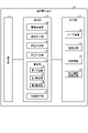
- FIG. 2 is a diagram showing an example of the configuration of the operation management device according to the first embodiment.
- the operation management device 10 includes a communication unit 11, a storage unit 12, and a processing unit 13.
- the communication unit 11 is communicably connected to the network 7 and transmits / receives information to / from the ground control device 4, the interlocking control device 5, or the train 2.
- the communication unit 11 may be further connected to the network 6 and may be configured to transmit / receive information to / from the train 2 via the wireless device 3 without the intervention of the ground control device 4. Further, the communication unit 11 may be configured to transmit / receive information to / from the train 2 via a mobile communication network (not shown).
- the storage unit 12 stores timetable information 30, route information 31, train information 32, minimum headway information 33, and the like.
- the timetable information 30 includes, for example, travel route information and stop station time information for each train ID (Identifier).
- the train ID is identification information uniquely assigned to each train 2.
- the travel route information is information indicating the travel route of the train 2.
- the stop station time information includes information indicating the arrival time of the train 2 at each station and information indicating the departure time of the train 2 from each station.
- the route information 31 includes, for example, information such as a traveling direction and a position of a unit route for each route ID.
- the route ID is identification information uniquely assigned to each unit route.
- a unit route is the smallest unit of a route including one or more blocks, and a plurality of unit routes are combined to form a traveling route of train 2.
- the block divides the orbit and is also called a section.
- the traveling direction is the traveling direction of the train 2 in the unit route, and either up or down is set.
- the train information 32 includes train status information and train control information of each train 2.
- the train state information includes information indicating the traveling position of the train 2 and information indicating the traveling speed of the train 2.
- the minimum headway information 33 includes information indicating the minimum headway at each station. The minimum headway is the minimum departure / arrival time between the preceding train and the following train, which allows the following train to travel without being decelerated by the brake check pattern.
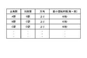
- FIG. 3 is a diagram showing an example of the minimum headway information according to the first embodiment.
- the minimum headway information shown in FIG. 3 includes a "departure station”, a "arrival station”, a “direction”, and a “minimum headway”, and these informations are associated with each other.
- Departure station is information indicating the departure station where train 2 departs.
- the "arrival station” is information indicating an arrival station, which is the station where the train 2 departs from the departure station and then arrives next.
- the "direction” is the traveling direction of the train 2, and is information on going up or down.
- the "minimum headway” is the minimum departure / arrival time between the preceding train and the following train, which allows the following train to travel without being decelerated by the brake check pattern.
- the brake check pattern is used due to the approach of the following train to the preceding train or the unconfigured course of the following train, for example, when the train 2 exceeds the indicated speed or the speed limit, or when the train 2 exceeds the indicated speed or the speed limit. It is used to activate the brake to decelerate or stop the train 2 when the train 2 is about to be exceeded.
- Such a brake check pattern is also referred to as a speed check pattern.
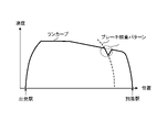
- FIG. 4 is a diagram for explaining a brake verification pattern in the railway system according to the first embodiment.
- a run curve showing a change in the speed of the train 2 from the departure station to the arrival station and a brake check pattern set for the train 2 are shown.
- the on-board device 50 of the train 2 traveling on the run curve shown in FIG. 4 is set to the train 2 when the departure delay to the next station of the preceding train occurs and the stop position information is received from the ground control device 4.
- the permissible speed is calculated based on the brake check pattern and the position of the train 2, and the speed of the train 2 is controlled based on the permissible speed while comparing with the speed of the train 2.
- the speed of the train 2 is decelerated according to the brake check pattern in front of the arrival station.
- the processing unit 13 shown in FIG. 2 includes an information acquisition unit 20, a course control unit 21, a delay determination unit 22, a departure / arrival determination unit 23, a calculation unit 24, and an acceleration instruction unit 25.
- the information acquisition unit 20 acquires train information of each train 2 via the ground control device 4, and stores the acquired train information of each train 2 in the storage unit 12.
- the course control unit 21 makes each train 2 travel the course according to the timetable information at the time according to the timetable information. Generates the course control information of train 2.
- the operation management device 10 outputs the generated course control information of each train 2 to the interlocking control device 5.
- the delay determination unit 22 determines whether or not each train 2 has a delay in arriving at the next station based on the train information of each train 2 stored in the storage unit 12. Then, the delay determination unit 22 sets the train 2 that has determined that the arrival delay at the next station has occurred as the preceding train. For example, the delay determination unit 22 determines that the arrival delay of the preceding train to the next station has occurred when the arrival delay time of the preceding train to the next station is equal to or longer than a predetermined time.
- the departure / arrival determination unit 23 determines whether or not the preceding train, which has been determined by the delay determination unit 22 to have a delay in arrival at the next station, has arrived at the next station, based on the train information stored in the storage unit 12. do. Further, the departure / arrival determination unit 23 determines whether or not the preceding train, which is determined by the delay determination unit 22 to have a delay in arrival at the next station, departs from the next station.
- the calculation unit 24 arrives at the next station of the target train, which is a succeeding train following the preceding train determined by the delay determination unit 22 based on the train information stored in the storage unit 12. Is calculated.
- the calculation unit 24 is targeted regardless of whether the target train is stopped at the previous station, which is a station before the next station, or the target train is traveling from the previous station to the next station.
- the target arrival time at the next station of the train can be calculated.
- the calculation unit 24 includes a first calculation unit 26, a second calculation unit 27, and a third calculation unit 28.
- the first calculation unit 26 sets the arrival target time of the target train, which is the following train following the preceding train, to the next station. 1 Calculated as the target arrival time.
- the preceding train may be described as the preceding train 2A, and the following train may be described as the following train 2B.
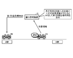
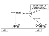
- FIG. 5 is a diagram for explaining the calculation of the first arrival target time by the first calculation unit of the operation management device according to the first embodiment.
- the preceding train 2A has a delay in arriving at the next station, B station, but the succeeding train 2B is stopped at the previous station, A station.
- the degree of delay in arrival of the preceding train 2A at station B is unknown in the operation management device 10.
- the first calculation unit 26 considers that when the preceding train 2A and the following train 2B are in the state shown in FIG. 5, a certain delay time occurs for the preceding train 2A to arrive at the B station, and the preceding train 2A
- the first arrival target time of the following train 2B is calculated regardless of the degree of arrival delay at station B.
- the “constant delay time” is set to a delay time so that the following train 2B does not get too close to the preceding train 2A regardless of the degree of arrival delay of the preceding train 2A.
- Constant delay time is the maximum or average value of the latest train 2 delay time, the maximum or average train 2 delay time that occurs frequently in the same time zone or between the same stations, or the same time zone and between the same stations. It is the maximum value or the average value of the delay time of the train 2 that frequently occurs in.
- the “constant delay time” may be, for example, a delay time predicted from the statistical results of the delay time of the past train 2 in the same time zone and between the same stations.
- the first calculation unit 26 causes the following train 2B to execute the running on the slowest run curve among the plurality of run curves.
- the time can also be calculated as the first arrival target time.
- the information of the first arrival target time calculated by the first calculation unit 26 is transmitted from the communication unit 11 of the operation management device 10 to the following train 2B. ..
- the on-board device 50 of the following train 2B receives the information of the first arrival target time from the operation management device 10, the on-board device 50 performs a run curve according to the first arrival target time based on the received information of the first arrival target time. decide.
- the run curve is a speed curve that regulates the change in running speed from the previous station to the next station.
- the on-board device 50 has a function of automatically operating the train 2
- the on-board device 50 of the following train 2B runs the target train on the determined run curve.
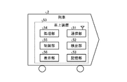
- FIG. 6 is a diagram showing an example of the configuration of the on-board device included in the train according to the first embodiment.
- the on-board device 50 includes a communication unit 51, a detection unit 52, a storage unit 53, a processing unit 54, a control unit 55, and a display unit 56.
- the communication unit 51 is wirelessly connected to the wireless device 3 so as to be able to communicate with the wireless device 3, and transmits / receives information to / from the ground control device 4 or the operation management device 10. For example, the communication unit 51 receives train control information from the ground control device 4 via the wireless device 3, or information on the arrival target time of the train 2 from the operation management device 10 via the ground control device 4 and the wireless device 3. Or receive.
- the detection unit 52 detects the position and speed of the train 2.
- the detection unit 52 detects the position and speed of the train 2 based on the wheel rotation speed detected by the rotation detector (not shown) provided in the train 2, but the GPS (Global) (Global) (not shown) provided in the train 2 detects the position and speed of the train 2.
- Positioning System It is also possible to detect the position and speed of train 2 based on the position information output from the receiver.
- the detection unit 52 outputs train status information to the communication unit 51 based on the result of detecting the position and speed of the train 2.
- the train state information includes, for example, a train ID, position information indicating the position of the train 2, speed information indicating the speed of the train 2, and driving direction information indicating the traveling direction of the train 2.
- the communication unit 51 transmits the train state information output from the detection unit 52 to the ground control device 4 via the wireless device 3.
- the storage unit 53 stores run curve information including information on a plurality of run curves having different characteristics for each station.
- FIG. 7 is a diagram showing an example of run curve information according to the first embodiment.
- the run curve information shown in FIG. 7 includes "departure station”, “arrival station”, “direction”, “running time”, “run curve ID”, “mode”, and “run curve”, and these information are associated with each other. Has been done.
- the "departure station”, “arrival station”, and “direction” shown in FIG. 7 are the same as the "departure station", "arrival station”, and "direction” shown in FIG.
- the "Running time” is the running time of train 2 from the departure station to the arrival station when train 2 runs from the departure station to the arrival station according to the run curve, and the unit is seconds.
- the "run curve ID” is identification information unique to each run curve.
- the "mode” is a traveling mode defined by a run curve, and in the example shown in FIG. 7, there are a normal mode, a recovery mode, a first low speed mode, a second low speed mode, ..., And an nth low speed mode. n is an integer of 3 or more. The number of low-speed modes is not limited to 3 or more, and may be 2 or less.
- the normal mode is a run curve used when there is no delay in the starting train.
- the recovery mode is a run curve used when there is a delay in the starting train, and the running time is shorter than the running time when running in the run curve in the normal mode used when there is no delay in the starting train. Is the run curve that is defined.
- the n-th low-speed mode is a run curve used when there is a delay in the starting train, and is longer than the running time when traveling in the run curve of the normal mode. It is a run curve that regulates running at the running time.
- the running time in the second low speed mode is longer than the running time in the first low speed mode.
- the running time in the nth low speed mode is longer than the running time in the second low speed mode.
- Run curve includes run curve information.
- the run curve information is, for example, information related to each position from the departure station to the arrival station and the speed.
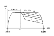
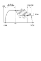
- FIG. 8 is a diagram showing an example of a plurality of run curves according to the first embodiment.
- the vertical axis shows the speed of the train 2
- the horizontal axis shows the position between the departure station and the arrival station.
- the departure station indicates the station where the train 2 departs
- the arrival station indicates the station where the train 2 departing from the departure station arrives next.
- the run curves C1, C2, C3 1 , C3 2 , ..., C3 n are speed curves that regulate the change in the traveling speed of the train 2 from the departure station to the arrival station.
- the run curve C1 is a run curve in the normal mode
- the run curve C2 is a run curve in the recovery mode
- the run curves C3 1 , C3 2 , ..., C3 n are run curves in the low speed mode.
- run curve C when each of the run curves C1, C2, C3 1 , C3 2 , ..., C3 n is shown without distinction, it may be described as run curve C.
- the run curve C1 is an example of a first run curve
- a plurality of run curves C3 1 , C3 2 , ..., C3 n is an example of a plurality of second run curves
- a run curve C2 is an example of a third run curve. ..
- the processing unit 54 of the on-board device 50 has a plurality of run curves C stored in the storage unit 53 based on the arrival target time information received by the communication unit 51. Among them, the run curve corresponding to the arrival target time received by the communication unit 51 is selected.
- the processing unit 54 is the communication unit among the plurality of run curves C1, C2, C3 1 , C3 2 , ..., C3 n shown in FIG. 8 based on the information of the arrival target time received by the communication unit 51. Select the run curve according to the first arrival target time received at 51.
- the processing unit 54 selects a run curve according to the first arrival target time based on the first arrival target time and the travel time of the run curve C. Further, when the train 2 is traveling between the A station and the B station, the processing unit 54 determines the first arrival target time, the distance of the train 2 to the B station, and the traveling time of each run curve C. Based on, the run curve according to the first arrival target time is selected.
- the processing unit 54 sets the run curve according to the first arrival target time.
- the run curve C3 n which is the slowest run curve, is selected.
- the processing unit 54 arrives at the arrival station at the arrival target time calculated by the operation management device 10 based on the arrival target time information received by the communication unit 51. Generate a run curve that defines the speed of train 2 to arrive.
- the on-board device 50 may be configured to be able to execute only one of the operation mode of the selection mode and the generation mode.
- control unit 55 controls the traveling speed of the train 2 based on the run curve selected or generated by the processing unit 54. As a result, the control unit 55 can run the train 2 at a speed according to the run curve.
- control unit 55 can display the run curve selected or generated by the processing unit 54 on the display unit 56.
- the driver of the train 2 can drive the train 2 at a speed according to the run curve by operating the train 2 according to the run curve displayed on the display unit 56.
- the on-board device 50 may be configured to be capable of executing only one of the control modes, the automatic driving mode and the manual driving mode.
- the second calculation unit 27 calculates the arrival target time of the following train 2B to the next station as the second arrival target time when the preceding train 2A arrives at the next station for each succeeding train 2B.
- the calculation of the second arrival target time by the second calculation unit 27 is performed when the following train 2B is stopped at the previous station or is traveling between the previous station and the next station.
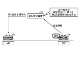
- FIG. 9 is a diagram for explaining the calculation of the second arrival target time by the second calculation unit of the operation management device according to the first embodiment.
- the degree of delay of the preceding train 2A can be known.
- the second arrival target time is calculated so that the delay is reduced.
- the second calculation unit 27 calculates the second arrival target time using the following equation (1) based on the timetable information 30, the train information 32, and the minimum headway information 33 stored in the storage unit 12. do.
- T2 is the second arrival target time
- t1 is the arrival time at the next station of the preceding train 2A
- t2 is the next station of the preceding train 2A.
- t3 is the minimum driving time interval.
- the second calculation unit 27 calculates, for example, the scheduled stop time at the next station of the preceding train 2A based on the stop station time information included in the timetable information 30.
- T2 t1 + t2 + t3 ... (1)
- the processing unit 54 selects a run curve according to the second arrival target time based on the second arrival target time and the travel time of the run curve C. Further, when the train 2 is traveling between the A station and the B station, the processing unit 54 determines the second arrival target time, the distance of the train 2 to the B station, and the traveling time of each run curve C. Based on, the run curve according to the second arrival target time is selected.
- the processing unit 54 manages the operation of the plurality of run curves C stored in the storage unit 53 based on the information of the second arrival target time received by the communication unit 51.
- the run curve corresponding to the second arrival target time calculated by the device 10 is selected.
- the processing unit 54 arrives at the arrival station at the second arrival target time based on the information of the second arrival target time received by the communication unit 51. Generate a run curve that defines the speed of train 2.
- control unit 55 controls the traveling speed of the train 2 based on the run curve selected or generated by the processing unit 54. As a result, the control unit 55 can run the train 2 at a speed according to the run curve according to the second arrival target time instead of the run curve corresponding to the first arrival target time.
- control unit 55 can display the run curve selected or generated by the processing unit 54 on the display unit 56.
- the driver of the train 2 replaces the run curve according to the first arrival target time with the speed according to the run curve according to the second arrival target time. Train 2 can be run at.
- the third calculation unit 28 calculates the arrival target time of the following train 2B to the next station as the third arrival target time when the preceding train 2A departs from the next station.
- the calculation of the third arrival target time by the third calculation unit 28 is performed when the following train 2B is stopped at the previous station or is traveling between the previous station and the next station.
- FIG. 10 is a diagram for explaining the calculation of the third arrival target time by the third calculation unit of the operation management device according to the first embodiment.
- the preceding train 2A departs from station B while the succeeding train 2B is traveling between stations A and B.
- the third calculation unit 28 calculates the third arrival target time so that the arrival delay of the following train 2B is reduced or eliminated.
- the third calculation unit 28 calculates the approachable time, which is the time when the following train 2B is predicted to be able to enter the B station, as the third arrival target time based on the train information 32, the minimum headway information 33, and the like. do.
- the processing unit 54 of the on-board device 50 in the following train 2B is based on the received information on the third arrival target time. Determine the run curve according to the third arrival target time.
- the processing unit 54 manages the operation of the plurality of run curves C stored in the storage unit 53 based on the information of the third arrival target time received by the communication unit 51.
- a run curve corresponding to the third arrival target time calculated by the device 10 is selected. For example, when the train 2 departs from station A, the processing unit 54 selects a run curve according to the third arrival target time based on the third arrival target time and the travel time of the run curve C. Further, when the train 2 is traveling between the A station and the B station, the processing unit 54 determines the third arrival target time, the distance of the train 2 to the B station, and the traveling time of each run curve C. Based on, the run curve according to the third arrival target time is selected.
- the processing unit 54 arrives at the arrival station at the third arrival target time based on the information of the third arrival target time received by the communication unit 51. Generate a run curve that defines the speed of train 2.
- control unit 55 controls the traveling speed of the train 2 based on the run curve selected or generated by the processing unit 54. As a result, the control unit 55 can run the train 2 at a speed according to the run curve according to the third arrival target time instead of the run curve corresponding to the second arrival target time.
- control unit 55 can display the run curve selected or generated by the processing unit 54 on the display unit 56.
- the driver of the train 2 replaces the run curve according to the second arrival target time with the speed according to the run curve according to the third arrival target time. Train 2 can be run at.
- the acceleration instruction unit 25 indicates that the preceding train 2A is at station B immediately before the following train 2B departs from station A or when the following train 2B is traveling between stations A and B.
- the full acceleration instruction can be transmitted to the communication unit 11 to the on-board device 50 of the following train 2B.
- the acceleration instruction unit 25 transmits a full acceleration instruction to the following train 2B at the timing when the following train 2B can enter the platform of the B station after the preceding train 2A departs from the B station. Let me.
- the processing unit 54 of the on-board device 50 in the following train 2B selects the fastest run curve among the plurality of run curves stored in the storage unit 53. select.
- the processing unit 54 selects the run curve C2, which is the fastest run curve among the run curves C1, C2, C3 1 , C3 2 , ..., C3 n .
- the control unit 55 controls the traveling speed of the train 2 based on the run curve C2 selected by the processing unit 54.
- the following train 2B can increase the speed and enter the station without decelerating due to the brake check pattern.
- the operation management device 10 can contribute to the delay recovery of the following train 2B.
- the operation management device 10 selectively transmits either one of the third arrival target time information and the full acceleration instruction to the on-board device 50.
- the operation management device 10 transmits either the third arrival target time information or the full acceleration instruction to the on-board device 50 according to the type of the train 2.
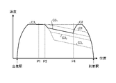
- FIG. 11 is shown by the processing unit of the on-board device based on each of the first arrival target time, the second arrival target time, and the third arrival target time calculated by the processing unit of the operation management device according to the first embodiment. It is a figure which shows an example of the selected run curve.
- the operation management device 10 transmits the information of the first arrival target time to the on-board device 50 of the following train 2B stopped at the station A.
- the processing unit 54 of the on-board device 50 in the following train 2B selects the run curve C3 n in the nth low speed mode, which is the slowest run curve according to the first arrival target time.
- the control unit 55 of the following train 2B causes the following train 2B to travel at a speed according to the run curve C3 n .
- the operation management device 10 determines that the preceding train 2A has arrived at the B station while the following train 2B departing from the A station is traveling at a speed according to the run curve C3 n , the on-board device of the following train 2B Information on the second arrival target time is transmitted from the operation management device 10 to 50.
- the information on the second arrival target time is transmitted to the on-board device 50 of the following train 2B while the following train 2B is at the position P1.
- the processing unit 54 of the on-board device 50 in the following train 2B selects the run curve C3 1 in the first low speed mode, which has a shorter running time than the run curve C3 n in the nth low speed mode, as the run curve according to the second arrival target time. ..
- the control unit 55 of the following train 2B causes the following train 2B to travel at a speed according to the run curve C31.
- the sections from the departure station to the position P2 are common sections for the plurality of run curves C1, C2, C3 1 , C3 2 , ..., C3 n , and the common speeds in the common sections of the curves. It has characteristics. Therefore, when the preceding train 2A arrives at the B station while the following train 2B is at the position P1 before the position P2, the run curve selected by the processing unit 54 changes from the run curve C3 n to the run curve C3 1 . Although it switches, the speed at the position P1 does not change between the run curve C3 n and the run curve C3 1 .
- the processing unit 54 can easily select the run curve. For example, the processing unit 54 subtracts the time taken for the following train 2B to move from the station A to the position P1 from the running time of each run curve, so that the arrival time when the train 2 is run on each run curve can be obtained. It can be easily calculated, and the run curve can be easily selected.
- the position P2 is an example of a specific position.
- the operation management device 10 can determine the degree of delay of the preceding train 2A when the preceding train 2A arrives at station B, the on-board device of the following train 2B sets the second arrival target time according to the degree of delay of the preceding train 2A. Send to 50.
- the delay of the following train 2B is increased when the operation management device 10 is traveling on the run curve C3 n of the nth low speed mode, which is the slowest at the first arrival target time, the delay of the following train 2B is increased.
- the following train 2B can be run so as to recover.
- the operation management device 10 determines that the preceding train 2A departs from the B station when the following train 2B is at the position P4 after the preceding train 2A arrives at the B station, the operation management device 10 Information on the third arrival target time or a full acceleration instruction is transmitted from to the on-board device 50 of the following train 2B.
- the processing unit 54 of the on-board device 50 in the following train 2B selects the run curve C2 in the recovery mode in which the running time is shorter than the run curve C1 in the normal mode as the run curve in response to the third arrival target time or the full acceleration instruction. As a result, the on-board device 50 can drive the following train 2B so that the delay of the following train 2B is further recovered.
- the on-board device 50 can travel on the run curve C2 in the recovery mode, which has a shorter running time than the run curve C1 in the normal mode, the delay is further increased as compared with the case where there is no run curve C2 in the recovery mode. You can drive to recover.
- FIG. 11 shows an example in which the arrival delay of the preceding train 2A to the B station occurs before the succeeding train 2B departs from the A station.
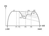
- FIG. 12 is shown by the processing unit of the on-board device based on each of the first arrival target time, the second arrival target time, and the third arrival target time calculated by the processing unit of the operation management device according to the first embodiment. It is a figure which shows the other example of a selected run curve.
- the processing unit 54 of the on-board device 50 in the following train 2B has a plurality of run curves C1, C2, C3 1 , C3 2 , ... -Select the run curve C2 in the normal mode from among C3 n .
- the calculation unit 24 of the operation management device 10 can calculate the arrival target time of the following train 2B to the B station even when the arrival delay of the preceding train 2A to the B station has not occurred.
- the calculation unit 24 calculates the arrival target time of the following train 2B to the B station based on, for example, the timetable information 30 and the train information 32 stored in the storage unit 12.
- the arrival target time is transmitted from the communication unit 11 to the on-board device 50 of the following train 2B.
- the processing unit 54 of the on-board device 50 in the following train 2B selects the run curve C2 in the normal mode based on the arrival target time transmitted from the operation management device 10.
- the operation management device 10 determines that the arrival delay of the preceding train 2A to the B station has occurred while the following train 2B departs from the A station and is on the line at the position P1. If this is the case, information on the first arrival target time is transmitted from the operation management device 10 to the on-board device 50 of the following train 2B. Then, the processing unit 54 of the on-board device 50 in the following train 2B selects the run curve C3 n of the nth low speed mode, which is the slowest run curve according to the first arrival target time.
- the plurality of run curves C1, C2, C3 1 , C3 2 , ..., C3 n have common speed characteristics in the section from the departure station to the position P2 as shown in FIG. There is. Therefore, if the arrival delay of the preceding train 2A to the B station occurs while the following train 2B is in the position P1 before the position P2, the run curve selected by the processing unit 54 is the run curve from the run curve C1. It switches to C3 n , but the velocity at position P1 does not change between run curve C1 and run curve C3 n .
- the processing unit 54 can easily select the run curve. ..
- the processing unit 54 subtracts the time taken for the following train 2B to move from the station A to the position P1 from the running time of each run curve, so that the arrival time when the train 2 is run on each run curve can be obtained. It can be easily calculated, and the run curve can be easily selected.
- the operation management device 10 determines that the preceding train 2A has arrived at the B station while the following train 2B is at the position P3 after the arrival delay of the preceding train 2A to the B station occurs.
- Information on the second arrival target time is transmitted from the operation management device 10 to the on-board device 50 of the following train 2B.
- the processing unit 54 of the on-board device 50 in the following train 2B selects the run curve C3 1 in the first low speed mode, which has a shorter running time than the run curve C3 n in the nth low speed mode, as the run curve according to the second arrival target time. ..
- the operation management device 10 can determine the degree of delay of the preceding train 2A when the preceding train 2A arrives at station B, the second arrival target time according to the degree of delay of the preceding train 2A is set to the vehicle of the following train 2B. It is transmitted to the upper device 50. As a result, even if the delay of the following train 2B is increased when the operation management device 10 is traveling on the run curve C3 n of the nth low speed mode, which is the slowest at the first arrival target time, the delay of the following train 2B is increased. The following train 2B can be run so as to recover.
- the operation management device 10 determines that the preceding train 2A departs from the B station when the following train 2B is at the position P4 after the preceding train 2A arrives at the B station, the operation management device 10 Information on the third arrival target time or a full acceleration instruction is transmitted from to the on-board device 50 of the following train 2B.
- the processing unit 54 of the on-board device 50 in the following train 2B selects the run curve C2 in the recovery mode in which the running time is shorter than the run curve C1 in the normal mode as the run curve in response to the third arrival target time or the full acceleration instruction. As a result, the following train 2B can be driven so that the delay of the following train 2B is further recovered.
- the on-board device 50 can travel on the run curve C2 in the recovery mode, which has a shorter running time than the run curve C1 in the normal mode, the delay is further increased as compared with the case where there is no run curve C2 in the recovery mode. You can drive to recover.
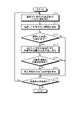
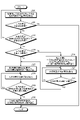
- FIG. 13 is a flowchart showing an example of processing by the processing unit of the operation management device according to the first embodiment.
- the processing unit 13 executes the processing shown in FIG. 13 at a predetermined cycle.
- the processing unit 13 of the operation management device 10 selects one unselected train 2 from the plurality of trains 2 (step S10), and acquires the position information of the selected train 2 (step). S11).
- step S12 determines whether or not the train selected in step S10 has a delay.
- step S12: Yes the processing unit 13 determines the succeeding train 2B of the selected train 2 as the target train for the arrival time adjustment (step S13). ). Then, the processing unit 13 determines whether or not the arrival target time of the target train determined in step S13 is in the calculation process (step S14).
- step S14 When the processing unit 13 determines that the arrival target time of the target train is not in the calculation process (step S14: No), the processing unit 13 starts the calculation process of the arrival target time of the target train (step S15).
- a calculation process is a process of steps S20 to S30 shown in FIG. 14, and will be described in detail later.
- the processing unit 13 is in the process of calculating the arrival target time for the target train, when the processing of step S15 is completed, when it is determined that the train selected in step S10 has not been delayed (step S12: No), or. If it is determined that there is (step S14: Yes), it is determined in step S10 whether or not there is an unselected train 2 (step S16). When the processing unit 13 determines that there is an unselected train 2 (step S16: Yes), the processing unit 13 shifts the processing to step S10. When the processing unit 13 determines that there is no unselected train 2 (step S16: No), the processing unit 13 ends the processing shown in FIG.
- FIG. 14 is a flowchart showing an example of calculation processing of the arrival target time by the processing unit of the operation management device according to the first embodiment.
- the processing unit 13 acquires the position information of the preceding train 2A, which is the train 2 preceding the target train (step S20).
- the processing unit 13 determines whether or not the preceding train 2A has departed from the next station (step S21). When the processing unit 13 determines that the preceding train 2A has not departed from the next station (step S21: No), the processing unit 13 determines whether or not the target train has departed immediately before or from the previous station. (Step S22). When the processing unit 13 determines that the target train is neither immediately before departure nor the target train has already departed (step S22: No), the processing unit 13 shifts the processing to step S20.
- the processing unit 13 determines whether or not the preceding train 2A has arrived at the next station. (Step S23).
- the processing unit 13 determines that the preceding train 2A has not arrived at the next station (step S23: No)
- the processing unit 13 considers that the preceding train 2A has a certain delay in arrival at the next station and proceeds to the next station of the target train.
- the arrival target time is calculated as the first arrival target time, and the calculated information on the first arrival target time is transmitted to the target train to the communication unit 11 (step S24).
- step S26 When the processing unit 13 determines that the preceding train 2A has arrived at the next station (step S26: Yes), or when it determines that the preceding train 2A has arrived at the next station (step S23: Yes).
- the arrival target time of the target train to the next station is calculated as the second arrival target time, and the calculated information on the second arrival target time is transmitted to the communication unit 11 (step S27).
- the processing unit 13 acquires the position information of the preceding train 2A (step S28), and determines whether or not the preceding train 2A departs from the next station and the target train can enter the next station (step). S29). When the processing unit 13 determines that the preceding train 2A has not departed from the next station or the target train cannot enter the next station (step S29: No), the processing unit 13 shifts the processing to step S28.
- step S29: Yes the processing unit 13 arrives at the third arrival target time of the target train to the next station. It is calculated as a target time, and information on the third arrival target time is transmitted to the communication unit 11 (step S30).
- step S30 the processing unit 13 ends the processing shown in FIG.
- FIG. 15 is a diagram showing an example of the hardware configuration of the operation management device according to the first embodiment.
- the operation management device 10 includes a computer including a processor 101, a memory 102, a communication device 103, and a bus 104.
- the processor 101, the memory 102, and the communication device 103 can send and receive information to and from each other by, for example, the bus 104.
- the storage unit 12 is realized by the memory 102.
- the communication unit 11 is realized by the communication device 103.
- the processor 101 executes the function of the processing unit 13 by reading and executing the program stored in the memory 102.
- the processor 101 is, for example, an example of a processing circuit, and includes one or more of a CPU (Central Processing Unit), a DSP (Digital Signal Processor), and a system LSI (Large Scale Integration).
- the memory 102 includes one or more of RAM (Random Access Memory), ROM (Read Only Memory), flash memory, EPROM (Erasable Programmable Read Only Memory), and EEPROM (registered trademark) (Electrically Erasable Programmable Read Only Memory). include. Further, the memory 102 includes a recording medium in which a computer-readable program is recorded. Such recording media include one or more of non-volatile or volatile semiconductor memories, magnetic disks, flexible memories, optical discs, compact disks, and DVDs (Digital Versatile Discs).
- the operation management device 10 may include integrated circuits such as an ASIC (Application Specific Integrated Circuit) and an FPGA (Field Programmable Gate Array).
- the operation management device 10 may be composed of two or more devices. When the operation management device 10 is composed of two or more devices, each of the two or more devices has, for example, the hardware configuration shown in FIG. Communication between two or more devices is performed via the communication device 103. Further, the operation management device 10 may be composed of two or more server devices. For example, the operation management device 10 may be composed of a processing server and a data server.
- the railway system 100 includes a plurality of trains 2 and an operation management device 10.
- the operation management device 10 manages the operation of the target train with at least one of the plurality of trains 2 as the target train.
- the operation management device 10 includes a calculation unit 24 and a communication unit 11.
- the calculation unit 24 recalculates the target arrival time of the target train to the next station when the arrival delay of the preceding train 2A, which is the train traveling in front of the target train, occurs among the plurality of trains 2. Then, when the preceding train 2A arrives at the next station, the target arrival time of the target train at the next station is calculated.
- the communication unit 11 transmits the information of the arrival target time calculated by the calculation unit 24 to the target train.
- the operation management device 10 suppresses the following train 2B from stopping between stations by calculating the arrival target time in a state where the delay degree of the preceding train 2A in which the arrival delay to the next station has occurred cannot be grasped. can do. Then, when the preceding train 2A arrives at the next station and the degree of delay of the preceding train 2A can be grasped, the operation management device 10 recalculates the arrival target time. As a result, the railway system 100 can suppress the arrival delay of the following train 2B to the next station while preventing the target train from stopping between the stations, and the arrival delay of the preceding train 2A to the next station occurs. Even in this case, the delay in arrival of the following train 2B at the next station can be suppressed.
- the calculation unit 24 calculates the target arrival time of the target train to the next station when the preceding train 2A departs from the next station. As a result, the railway system 100 can contribute to the delay recovery of the following train 2B.
- the calculation unit 24 determines in advance the arrival time of the preceding train 2A at the next station, the scheduled stop time at the next station of the preceding train 2A, and the next station.
- the target arrival time is calculated based on the departure / arrival time interval of train 2.
- the railway system 100 can suppress the delay in arrival of the following train 2B at the next station.
- the calculation unit 24 determines in advance that the arrival delay of the preceding train 2A to the next station is irrespective of the degree of the arrival delay of the preceding train 2A to the next station.
- the target arrival time is calculated assuming that it is a specified delay.
- the calculation unit 24 calculates the arrival target time while the target train is running.
- the railway system 100 can suppress the delay in arrival of the following train at the next station even when the arrival delay of the preceding train 2A to the next station occurs while the target train is running.
- the calculation unit 24 calculates the arrival target time when the arrival delay of the preceding train 2A to the next station occurs while the target train is stopped at the station in front of the next station.
- the railway system 100 can suppress the delay in arrival of the following train 2B to the next station even when the target train is stopped at the previous station and the arrival delay of the preceding train 2A to the next station occurs.
- each of the plurality of trains 2 includes a communication unit 51 and a processing unit 54.
- the communication unit 51 receives the arrival target time from the operation management device 10.
- the processing unit 54 determines a run curve that regulates the change in traveling speed from the previous station, which is the station immediately before the next station, to the next station, and determines the run curve according to the arrival target time received by the communication unit 51. ..
- each train 2 of the railway system 100 can travel using a run curve according to the arrival target time, and the railway system 100 can be a subsequent train even if the arrival delay of the preceding train 2A to the next station occurs. It is possible to suppress the delay in arrival at the next station of 2B.
- each of the plurality of trains 2 is provided with a storage unit 53 that stores information on a plurality of run curves that specify the traveling speeds from the previous station to the next station.
- the processing unit 54 determines one of the plurality of run curves as a run curve according to the arrival target time based on the arrival target time received by the communication unit 51. As a result, in the railway system 100, the run curve can be easily determined.
- the plurality of run curves C1, C2, C3 1 , C3 2 , ..., C3 n have a common curve from the departure station, which is the previous station, to the position P2, which is a specific position.
- the speed switching in the train 2 can be suppressed, and further, the run curve can be easily selected in the processing unit 54.
- the plurality of run curves are used when there is a delay in arrival at the next station of the preceding train 2A and a run curve C1 used when there is a delay in arrival at the next station of the preceding train 2A.
- a run curve C1 used when there is a delay in arrival at the next station of the preceding train 2A includes a plurality of run curves C3 1 , C3 2 , ..., C3 n with long minutes and a run curve C2 with a shorter running time than the run curve C1 used when there is a delay in arrival at the next station of the preceding train 2A. ..
- the run curve C1 is an example of the first run curve
- the run curves C3 1 , C3 2 , ..., C3 n are examples of the second run curve
- the run curve C2 is an example of the third run curve.
- the railway system 100 can accurately suppress the arrival delay of the following train 2B to the next station while preventing the target train from stopping between stations, and the arrival delay of the preceding train 2A to the next station is delayed. Even if it occurs, the delay in arrival of the following train 2B to the next station can be accurately suppressed.
- Embodiment 2 The railway system according to the second embodiment is different from the railway system according to the first embodiment in that the run curve information stored in the storage unit of the on-board device is different.
- the components having the same functions as those of the first embodiment are designated by the same reference numerals and the description thereof will be omitted, and the differences from the railway system 100 of the first embodiment will be mainly described.
- FIG. 16 is a diagram showing an example of the configuration of the railway system according to the second embodiment.
- the railway system 100A according to the second embodiment is different from the railway system 100 in that it includes a plurality of trains 2C 1 to 2 cm instead of the plurality of trains 2 1 to 2 m .
- the plurality of trains 2C 1 to 2 cm are different from the plurality of trains 2 1 to 2 m in that the on-board device 50A is provided in place of the on-board device 50.
- train 2C when each of trains 2C 1 to 2 cm is shown without distinction, it is referred to as train 2C.
- FIG. 17 is a diagram showing an example of the configuration of the on-board device included in the train according to the second embodiment.
- the on-board device 50A differs from the on-board device 50 in that it includes a storage unit 53A that stores information on a plurality of run curves different from the information on the plurality of run curves stored in the storage unit 53.
- FIG. 18 is a diagram showing an example of a plurality of run curves according to the second embodiment.
- FIG. 19 is a diagram showing another example of the plurality of run curves according to the second embodiment.
- the run curve C1 in the normal mode the run curve C2 in the recovery mode
- the run curves C3 1 , C3 2 , ..., C3 n in the low speed mode are shown.
- the run curve of is stored in the storage unit 53A.
- the low-speed mode run curves C3 1 , C3 2 , ..., C3 n shown in FIG. 18 have lower maximum speeds than the low-speed mode run curves C3 1 , C3 2 , ..., C3 n shown in FIG. It is suppressed.
- Trains 2 1 to 2 m and 2C 1 to 2 C m consume more power as the speed increases, even when traveling the same distance. Therefore, the train 2C 1 to 2 cm can reduce the power consumption when traveling in the low speed mode as compared with the train 2 1 to 2 m .
- the run curves C3 1 , C3 2 , ..., C3 n in the low speed mode shown in FIG. 18 have a constant velocity section which is a section in which the same speed continues from the departure station following a common acceleration section.
- the lengths of the speed sections are different from each other.
- the run time and minute of the run curves C3 1 , C3 2 , ..., C3 n in the low speed mode differ depending on the length of the constant velocity section.
- the run curves for various traveling times are prepared by adjusting the length of the constant velocity section in the run curve in the low speed mode.
- the normal mode run curve C1 and the low speed mode run curve C3 1 , C3 2 , ..., C3 n shown in FIG. 18 have different speeds in the constant velocity section, but the section where full acceleration is performed from the departure station to the position P10.
- the acceleration section is also included as the recommended section for switching the first run curve. Therefore, when switching from any of the low-speed run curves C3 1 , C3 2 , ..., C3 n to the normal mode run curve C1 on trains 2C 1 to 2 cm , the arrival target time is updated to the first run curve switching recommended section. If possible, acceleration / deceleration due to switching of the run curve does not occur.
- the lengths of the constant velocity sections are different from those of the low-speed mode run curves C3 1 , C3 2 , ..., C3 n shown in FIG. 18, it is recommended to switch the section from the departure station to the position P11. It has both as a section. Therefore, when switching from one of the low-speed run curves C3 1 , C3 2 , ..., C3 n to the other run curve on trains 2C 1 to 2 cm , the arrival target is the second run curve switching recommended section. If the time can be updated, acceleration / deceleration due to the change of the run curve does not occur, so that the increase in power consumption due to the acceleration / deceleration due to the change of the run curve does not occur.
- the processing unit 54 of the on-board device 50A calculates the second arrival target time using the minimum headway included in the minimum headway information 33, as in the processing unit 54 of the on-board device 50.
- the headway changes depending on the station approach speed.
- the following train 2B can enter the next station, but if the approach speed of the following train 2B to the next station is extremely low, it takes time to arrive at the next station. It takes too much and the minimum headway is greatly extended. Multiple run curves include those with a large minimum headway and those with a small minimum headway.
- the calculation unit 24 of the operation management device 10 calculates the arrival target time, as shown in FIG. 3, the minimum headway set only one for each station is used. Therefore, there may be a large difference between the minimum headway used when calculating the arrival target time and the minimum headway of the selected run curve, and highly accurate operation may not be realized. Therefore, in the on-board device 50A, a plurality of run curves C1, C2, C3 1 , C3 2 , ..., C3 n shown in FIG. 19 are stored in the storage unit so that a large difference does not appear in the minimum headway for each run curve. It can also be stored in 53A.
- the sections from the departure station to the position P20 have the same speed characteristics, and such sections are recommended run curve switching sections. Set. If the arrival target time can be updated in the recommended run curve switching section in the operation management device 10, acceleration / deceleration due to the run curve switching does not occur in the trains 2A 1 to 2 Am.
- the station approach section which is the approach section to arrive at the station, so that the approach speed to the arrival station does not change significantly.
- the speed characteristics have been adjusted.
- the speed of the train 2 in the station approach section is the station approach speed of the run curve where the minimum operation time interval indicating the departure / arrival interval is the smallest.
- the run curves C1, C2, C3 1 , C3 2 , ..., C3n shown in FIG. 19 are shown in FIGS. Compared to the run curves C1, C2, C3 1 , C3 2 , ..., C3 n , the difference in the minimum operating time interval between the two can be reduced.
- the speed in the station approach section in the run curve having a long running time is a constant speed.
- the run curves C1, C2, C3 1 , C3 2 , ..., C3 n may have the same speed in the station approach section. In this case, in the railway system 100A, the difference in the minimum headways between the two can be eliminated.
- the number of run curves C1, C2, C3 1 , C3 2 , ..., C3 n is the minimum operation time in which the speed indicates the departure / arrival interval to the arrival station in the approach section to the next station. It is set within a predetermined range with the station approach speed of the run curve where the distance is the smallest as near the center. As a result, in the railway system 100A, a large difference does not occur in the minimum headway of the run curve selected by the train 2C, and it is possible to support highly accurate operation.
- the configuration shown in the above embodiments is an example, and can be combined with another known technique, can be combined with each other, and does not deviate from the gist. It is also possible to omit or change a part of the configuration.
Landscapes
- Engineering & Computer Science (AREA)
- Mechanical Engineering (AREA)
- Business, Economics & Management (AREA)
- Tourism & Hospitality (AREA)
- Primary Health Care (AREA)
- General Business, Economics & Management (AREA)
- Economics (AREA)
- General Health & Medical Sciences (AREA)
- Human Resources & Organizations (AREA)
- Marketing (AREA)
- Theoretical Computer Science (AREA)
- Strategic Management (AREA)
- Physics & Mathematics (AREA)
- Health & Medical Sciences (AREA)
- General Physics & Mathematics (AREA)
- Power Engineering (AREA)
- Transportation (AREA)
- Train Traffic Observation, Control, And Security (AREA)
- Operations Research (AREA)
- Electric Propulsion And Braking For Vehicles (AREA)
- Management, Administration, Business Operations System, And Electronic Commerce (AREA)
Abstract
Description
図1は、実施の形態1にかかる鉄道システムの構成の一例を示す図である。実施の形態1にかかる鉄道システム100は、複数の列車21~2mと、複数の無線装置3と、地上制御装置4と、連動制御装置5と、運行管理装置10とを備える。mは、2以上の整数である。かかる鉄道システム100は、例えば、運行ダイヤにおける列車の間隔が数分程度であるような高密度線区に適用されるが、鉄道システム100の適用対象は、高密度線区に限定されない。
T2=t1+t2+t3 ・・・(1)
実施の形態2にかかる鉄道システムは、車上装置の記憶部に記憶されるランカーブ情報が実施の形態1にかかる鉄道システムと異なる。以下においては、実施の形態1と同様の機能を有する構成要素については同一符号を付して説明を省略し、実施の形態1の鉄道システム100と異なる点を中心に説明する。
Claims (15)
- 複数の列車と、
前記複数の列車のうち少なくとも1つの列車を対象列車として前記対象列車の運行を管理する運行管理装置と、を備え、
前記運行管理装置は、
前記複数の列車のうち前記対象列車の前を走行する列車である先行列車の次駅への到着遅延が発生した場合に、前記対象列車の前記次駅への到着目標時刻を算出し、前記先行列車が前記次駅に到着した場合に、前記対象列車の前記次駅への到着目標時刻を算出する算出部と、
前記算出部によって算出された前記到着目標時刻の情報を前記対象列車へ送信する通信部と、を備える
ことを特徴とする鉄道システム。 - 前記算出部は、
前記先行列車が前記次駅を出発した場合に、前記対象列車の前記次駅への到着目標時刻を算出する
ことを特徴とする請求項1に記載の鉄道システム。 - 前記算出部は、
前記先行列車が前記次駅に到着した場合に、前記先行列車の前記次駅への到着時刻、前記先行列車の前記次駅での停車予定時間、および前記次駅に予め定められた列車の発着時隔に基づいて、前記到着目標時刻を算出する
ことを特徴とする請求項1または2に記載の鉄道システム。 - 前記算出部は、
前記先行列車の前記次駅への到着遅延が発生した場合に、前記到着遅延の度合いと無関係に前記到着遅延が予め定められた遅延であるものとみなして前記到着目標時刻を算出する
ことを特徴とする請求項1から3のいずれか1つに記載の鉄道システム。 - 前記算出部は、
前記到着目標時刻の算出を前記対象列車の走行中に行う
ことを特徴とする請求項1から4のいずれか1つに記載の鉄道システム。 - 前記算出部は、
前記先行列車の次駅への到着遅延が発生した場合における前記到着目標時刻の算出を前記対象列車が前記次駅の前の駅に停車中に行う
ことを特徴とする請求項1から4のいずれか1つに記載の鉄道システム。 - 前記複数の列車の各々は、
前記運行管理装置から前記到着目標時刻を受信する通信部と、
前記次駅の1つ前の駅である前駅から前記次駅までの走行速度の変化を規定するランカーブであって前記通信部で受信された前記到着目標時刻に応じたランカーブを決定する処理部と、を備える
ことを特徴とする請求項1から6のいずれか1つに記載の鉄道システム。 - 前記複数の列車の各々は、
前記前駅から前記次駅までの走行速度を各々規定する複数のランカーブの情報を記憶する記憶部を備え、
前記処理部は、
前記通信部で受信された前記到着目標時刻に基づいて、前記複数のランカーブのうち1つのランカーブを前記到着目標時刻に応じたランカーブとして決定する
ことを特徴とする請求項7に記載の鉄道システム。 - 前記複数のランカーブは、
前記前駅から特定の位置までの速度特性が共通である
ことを特徴とする請求項8に記載の鉄道システム。 - 前記複数のランカーブは、
前記前駅から互いに共通の加速区間に続いて同一速度が継続する区間である等速区間を有し、前記等速区間は互いに長さが異なる
ことを特徴とする請求項8または9に記載の鉄道システム。 - 前記複数のランカーブは、
前記次駅への進入区間において、速度が、前記次駅への発着間隔を示す最小運転時隔が最も小さくなるランカーブの駅進入速度を中心付近とする予め定められた範囲内に設定される
ことを特徴とする請求項8または9に記載の鉄道システム。 - 前記複数のランカーブは、
前記先行列車の前記次駅への到着遅延がない場合に用いられる第1ランカーブと、
前記先行列車の前記次駅への到着遅延がある場合に用いられ、前記第1ランカーブよりも走行時分が長い複数の第2ランカーブと、
前記先行列車の前記次駅への到着遅延がある場合に用いられる前記第1ランカーブよりも走行時分が短い第3ランカーブと、を含む
ことを特徴とする請求項9から11のいずれか1つに記載の鉄道システム。 - 複数の列車のうち少なくとも1つの列車を対象列車として前記対象列車の運行を管理する運行管理装置であって、
前記複数の列車のうち前記対象列車の前を走行する列車である先行列車の次駅への到着遅延が発生した場合に、前記対象列車の前記次駅への到着目標時刻を算出し、前記先行列車が前記次駅に到着した場合に、前記対象列車の前記次駅への到着目標時刻を算出する算出部と、
前記算出部によって算出された前記到着目標時刻の情報を前記対象列車へ送信する通信部と、を備える
ことを特徴とする運行管理装置。 - 複数の列車のうち少なくとも1つの列車を対象列車とし前記複数の列車のうち前記対象列車の前を走行する列車である先行列車の次駅への到着遅延が発生した場合に、前記対象列車の前記次駅への到着目標時刻を算出する第1のステップと、
前記先行列車が前記次駅に到着した場合に、前記対象列車の前記次駅への到着目標時刻を算出する第2のステップと、
算出された前記到着目標時刻の情報を前記対象列車へ送信する第3のステップと、を含む
ことを特徴とする運行管理方法。 - 複数の列車のうち少なくとも1つの列車を対象列車とし前記複数の列車のうち前記対象列車の前を走行する列車である先行列車の次駅への到着遅延が発生した場合に、前記対象列車の前記次駅への到着目標時刻を算出する第1のステップと、
前記先行列車が前記次駅に到着した場合に、前記対象列車の前記次駅への到着目標時刻を算出する第2のステップと、
算出された前記到着目標時刻の情報を前記対象列車へ送信する第3のステップと、をコンピュータに実行させる
ことを特徴とする運行管理プログラム。
Priority Applications (4)
| Application Number | Priority Date | Filing Date | Title |
|---|---|---|---|
| JP2021519689A JP6980152B1 (ja) | 2020-11-04 | 2020-11-04 | 鉄道システム、運行管理装置、運行管理方法、および運行管理プログラム |
| PCT/JP2020/041225 WO2022097207A1 (ja) | 2020-11-04 | 2020-11-04 | 鉄道システム、運行管理装置、運行管理方法、および運行管理プログラム |
| CN202080106588.2A CN116547188B (zh) | 2020-11-04 | 2020-11-04 | 铁路系统、运行管理装置、运行管理方法 |
| US18/246,342 US11814090B2 (en) | 2020-11-04 | 2020-11-04 | Railroad system, operation management device, operation management method, and non-transitory storage medium to store operation management program |
Applications Claiming Priority (1)
| Application Number | Priority Date | Filing Date | Title |
|---|---|---|---|
| PCT/JP2020/041225 WO2022097207A1 (ja) | 2020-11-04 | 2020-11-04 | 鉄道システム、運行管理装置、運行管理方法、および運行管理プログラム |
Publications (1)
| Publication Number | Publication Date |
|---|---|
| WO2022097207A1 true WO2022097207A1 (ja) | 2022-05-12 |
Family
ID=78870837
Family Applications (1)
| Application Number | Title | Priority Date | Filing Date |
|---|---|---|---|
| PCT/JP2020/041225 Ceased WO2022097207A1 (ja) | 2020-11-04 | 2020-11-04 | 鉄道システム、運行管理装置、運行管理方法、および運行管理プログラム |
Country Status (4)
| Country | Link |
|---|---|
| US (1) | US11814090B2 (ja) |
| JP (1) | JP6980152B1 (ja) |
| CN (1) | CN116547188B (ja) |
| WO (1) | WO2022097207A1 (ja) |
Families Citing this family (1)
| Publication number | Priority date | Publication date | Assignee | Title |
|---|---|---|---|---|
| US20240359716A1 (en) * | 2021-11-11 | 2024-10-31 | Mitsubishi Electric Corporation | Automatic train operation assistance device, automatic train operation assistance system, and automatic train operation assistance method |
Citations (4)
| Publication number | Priority date | Publication date | Assignee | Title |
|---|---|---|---|---|
| JPH09104347A (ja) * | 1995-10-13 | 1997-04-22 | Hitachi Ltd | 列車制御システム |
| WO2016084197A1 (ja) * | 2014-11-27 | 2016-06-02 | 三菱電機株式会社 | 列車運転間隔制御システム及び列車運転間隔制御装置 |
| JP2017158330A (ja) * | 2016-03-02 | 2017-09-07 | 公益財団法人鉄道総合技術研究所 | プログラム及び予測制御運転曲線作成装置 |
| JP2018135018A (ja) * | 2017-02-22 | 2018-08-30 | 東芝インフラシステムズ株式会社 | 運行制御システム |
Family Cites Families (18)
| Publication number | Priority date | Publication date | Assignee | Title |
|---|---|---|---|---|
| JPH05124514A (ja) | 1991-11-05 | 1993-05-21 | Toshiba Corp | 車両運行管理制御装置 |
| JP3574233B2 (ja) | 1995-09-18 | 2004-10-06 | 東海旅客鉄道株式会社 | 列車運転時隔制御方法及び装置 |
| JP2005335505A (ja) | 2004-05-26 | 2005-12-08 | Mitsubishi Heavy Ind Ltd | 車両運行方法、中央運行管理装置、分散運行管理装置、及び新交通システム |
| JP6096596B2 (ja) * | 2013-05-30 | 2017-03-15 | 三菱重工業株式会社 | 運行管理装置、運行管理方法、車両、車両交通システム及びプログラム |
| JP5972829B2 (ja) * | 2013-05-30 | 2016-08-17 | 三菱重工業株式会社 | 運行管理装置、運行管理方法、車両、車両交通システム及びプログラム |
| US10407085B2 (en) * | 2014-04-21 | 2019-09-10 | Mitsubishi Electric Corporation | Train travel prediction device and train travel prediction method |
| AU2015254431B2 (en) | 2014-04-28 | 2018-06-14 | Hitachi, Ltd. | Driving assistance system |
| CN106828540B (zh) * | 2017-01-22 | 2019-06-18 | 北京交通大学 | 基于列车运行等级的列车运行控制方法 |
| JP7080019B2 (ja) | 2017-06-02 | 2022-06-03 | 株式会社日立製作所 | 列車運行制御装置 |
| KR102368602B1 (ko) * | 2017-06-30 | 2022-03-02 | 현대자동차주식회사 | 차량 및 그를 위한 정보 제공 방법 |
| JP7066365B2 (ja) * | 2017-10-16 | 2022-05-13 | 株式会社日立製作所 | ダイヤ作成装置および自動列車制御システム |
| JP7057199B2 (ja) * | 2018-04-16 | 2022-04-19 | 株式会社日立製作所 | ダイヤ分析支援装置及び方法 |
| JP7139169B2 (ja) | 2018-07-05 | 2022-09-20 | 東日本旅客鉄道株式会社 | 列車自動運転システムおよび自動運転装置 |
| CN109146758B (zh) * | 2018-08-29 | 2021-06-18 | 山东交通职业学院 | 一种基于客流的列车运行延误调整方法及系统 |
| JP7021055B2 (ja) | 2018-11-20 | 2022-02-16 | 株式会社東芝 | 情報処理装置、その方法及びコンピュータプログラム |
| CN109858154A (zh) * | 2019-01-31 | 2019-06-07 | 广州地铁设计研究院股份有限公司 | 一种基于多目标优化的列车节能运行方法 |
| JP7399627B2 (ja) * | 2019-04-25 | 2023-12-18 | 株式会社日立製作所 | ダイヤ作成装置、ダイヤ作成方法、及び自動車両制御システム |
| CN111422223B (zh) * | 2020-06-09 | 2020-09-08 | 北京和利时系统工程有限公司 | 一种高速铁路列车的速度自动控制方法和装置 |
-
2020
- 2020-11-04 WO PCT/JP2020/041225 patent/WO2022097207A1/ja not_active Ceased
- 2020-11-04 US US18/246,342 patent/US11814090B2/en active Active
- 2020-11-04 CN CN202080106588.2A patent/CN116547188B/zh active Active
- 2020-11-04 JP JP2021519689A patent/JP6980152B1/ja active Active
Patent Citations (4)
| Publication number | Priority date | Publication date | Assignee | Title |
|---|---|---|---|---|
| JPH09104347A (ja) * | 1995-10-13 | 1997-04-22 | Hitachi Ltd | 列車制御システム |
| WO2016084197A1 (ja) * | 2014-11-27 | 2016-06-02 | 三菱電機株式会社 | 列車運転間隔制御システム及び列車運転間隔制御装置 |
| JP2017158330A (ja) * | 2016-03-02 | 2017-09-07 | 公益財団法人鉄道総合技術研究所 | プログラム及び予測制御運転曲線作成装置 |
| JP2018135018A (ja) * | 2017-02-22 | 2018-08-30 | 東芝インフラシステムズ株式会社 | 運行制御システム |
Also Published As
| Publication number | Publication date |
|---|---|
| JPWO2022097207A1 (ja) | 2022-05-12 |
| CN116547188B (zh) | 2024-01-30 |
| US20230311964A1 (en) | 2023-10-05 |
| CN116547188A (zh) | 2023-08-04 |
| US11814090B2 (en) | 2023-11-14 |
| JP6980152B1 (ja) | 2021-12-15 |
Similar Documents
| Publication | Publication Date | Title |
|---|---|---|
| JP5944229B2 (ja) | 列車制御装置 | |
| JP5271772B2 (ja) | 列車運行制御方法および車上制御装置 | |
| JP5171712B2 (ja) | 踏切制御装置 | |
| RU2008109009A (ru) | Способ и устройство для оптимизации движения поезда с использованием сигнальной информации | |
| JP5619632B2 (ja) | 移動体制御システム | |
| US20190375441A1 (en) | Controller, system and method for vehicle control | |
| KR102542081B1 (ko) | 철도 인프라 및 차량 운행조건에 대한 정보를 이용한 열차 제어 시스템 및 이를 이용한 열차 제어 방법 | |
| CN104969135A (zh) | 轨道交通网络中的车辆控制系统 | |
| CN115230783A (zh) | 一种列车安全包络确定方法及装置 | |
| JP6980152B1 (ja) | 鉄道システム、運行管理装置、運行管理方法、および運行管理プログラム | |
| WO2015146587A1 (ja) | 列車制御装置および制御方法 | |
| JPH0976914A (ja) | 列車運行制御方法及び装置 | |
| JP2005231447A (ja) | 列車運転支援装置 | |
| JP7285647B2 (ja) | 列車運行管理装置および列車運行管理方法 | |
| US20170210405A1 (en) | Train control device | |
| JP2019013112A (ja) | 列車制御システム及び方法 | |
| US20210311497A1 (en) | Operation management apparatus, operation management method, and traffic system | |
| JP7595499B2 (ja) | 鉄道システム、通過時刻調整装置、通過時刻調整方法、および通過時刻調整プログラム | |
| JP2005280542A (ja) | Atc/o装置 | |
| HK40092519B (zh) | 铁路系统、运行管理装置、运行管理方法 | |
| HK40092519A (zh) | 铁路系统、运行管理装置、运行管理方法 | |
| JP7466494B2 (ja) | 列車制御システム及び列車制御装置 | |
| JP2002053044A (ja) | 自動運転車両の運行制御システム、運行管理装置及び自動運転車両 | |
| JP2018192880A (ja) | 進路制御装置、列車制御システム、進路制御方法、および進路制御プログラム | |
| KR20100127518A (ko) | 자동운행 차량 시스템에서의 차량의 분산 동적 경로제어 |
Legal Events
| Date | Code | Title | Description |
|---|---|---|---|
| ENP | Entry into the national phase |
Ref document number: 2021519689 Country of ref document: JP Kind code of ref document: A |
|
| 121 | Ep: the epo has been informed by wipo that ep was designated in this application |
Ref document number: 20960761 Country of ref document: EP Kind code of ref document: A1 |
|
| WWE | Wipo information: entry into national phase |
Ref document number: 202327018121 Country of ref document: IN |
|
| WWE | Wipo information: entry into national phase |
Ref document number: 202080106588.2 Country of ref document: CN |
|
| NENP | Non-entry into the national phase |
Ref country code: DE |
|
| 122 | Ep: pct application non-entry in european phase |
Ref document number: 20960761 Country of ref document: EP Kind code of ref document: A1 |