WO2022090757A1 - 電気デバイス用正極材料並びにこれを用いた電気デバイス用正極および電気デバイス - Google Patents
電気デバイス用正極材料並びにこれを用いた電気デバイス用正極および電気デバイス Download PDFInfo
- Publication number
- WO2022090757A1 WO2022090757A1 PCT/IB2020/000884 IB2020000884W WO2022090757A1 WO 2022090757 A1 WO2022090757 A1 WO 2022090757A1 IB 2020000884 W IB2020000884 W IB 2020000884W WO 2022090757 A1 WO2022090757 A1 WO 2022090757A1
- Authority
- WO
- WIPO (PCT)
- Prior art keywords
- positive electrode
- solid electrolyte
- active material
- electrode active
- sulfur
- Prior art date
- Legal status (The legal status is an assumption and is not a legal conclusion. Google has not performed a legal analysis and makes no representation as to the accuracy of the status listed.)
- Ceased
Links
Images





Classifications
-
- H—ELECTRICITY
- H01—ELECTRIC ELEMENTS
- H01M—PROCESSES OR MEANS, e.g. BATTERIES, FOR THE DIRECT CONVERSION OF CHEMICAL ENERGY INTO ELECTRICAL ENERGY
- H01M4/00—Electrodes
- H01M4/02—Electrodes composed of, or comprising, active material
- H01M4/36—Selection of substances as active materials, active masses, active liquids
- H01M4/38—Selection of substances as active materials, active masses, active liquids of elements or alloys
-
- H—ELECTRICITY
- H01—ELECTRIC ELEMENTS
- H01M—PROCESSES OR MEANS, e.g. BATTERIES, FOR THE DIRECT CONVERSION OF CHEMICAL ENERGY INTO ELECTRICAL ENERGY
- H01M10/00—Secondary cells; Manufacture thereof
- H01M10/05—Accumulators with non-aqueous electrolyte
- H01M10/052—Li-accumulators
-
- H—ELECTRICITY
- H01—ELECTRIC ELEMENTS
- H01M—PROCESSES OR MEANS, e.g. BATTERIES, FOR THE DIRECT CONVERSION OF CHEMICAL ENERGY INTO ELECTRICAL ENERGY
- H01M10/00—Secondary cells; Manufacture thereof
- H01M10/05—Accumulators with non-aqueous electrolyte
- H01M10/052—Li-accumulators
- H01M10/0525—Rocking-chair batteries, i.e. batteries with lithium insertion or intercalation in both electrodes; Lithium-ion batteries
-
- H—ELECTRICITY
- H01—ELECTRIC ELEMENTS
- H01M—PROCESSES OR MEANS, e.g. BATTERIES, FOR THE DIRECT CONVERSION OF CHEMICAL ENERGY INTO ELECTRICAL ENERGY
- H01M10/00—Secondary cells; Manufacture thereof
- H01M10/05—Accumulators with non-aqueous electrolyte
- H01M10/056—Accumulators with non-aqueous electrolyte characterised by the materials used as electrolytes, e.g. mixed inorganic/organic electrolytes
- H01M10/0561—Accumulators with non-aqueous electrolyte characterised by the materials used as electrolytes, e.g. mixed inorganic/organic electrolytes the electrolyte being constituted of inorganic materials only
- H01M10/0562—Solid materials
-
- H—ELECTRICITY
- H01—ELECTRIC ELEMENTS
- H01M—PROCESSES OR MEANS, e.g. BATTERIES, FOR THE DIRECT CONVERSION OF CHEMICAL ENERGY INTO ELECTRICAL ENERGY
- H01M4/00—Electrodes
- H01M4/02—Electrodes composed of, or comprising, active material
- H01M4/13—Electrodes for accumulators with non-aqueous electrolyte, e.g. for lithium-accumulators; Processes of manufacture thereof
-
- H—ELECTRICITY
- H01—ELECTRIC ELEMENTS
- H01M—PROCESSES OR MEANS, e.g. BATTERIES, FOR THE DIRECT CONVERSION OF CHEMICAL ENERGY INTO ELECTRICAL ENERGY
- H01M4/00—Electrodes
- H01M4/02—Electrodes composed of, or comprising, active material
- H01M4/62—Selection of inactive substances as ingredients for active masses, e.g. binders, fillers
-
- H—ELECTRICITY
- H01—ELECTRIC ELEMENTS
- H01M—PROCESSES OR MEANS, e.g. BATTERIES, FOR THE DIRECT CONVERSION OF CHEMICAL ENERGY INTO ELECTRICAL ENERGY
- H01M4/00—Electrodes
- H01M4/02—Electrodes composed of, or comprising, active material
- H01M4/62—Selection of inactive substances as ingredients for active masses, e.g. binders, fillers
- H01M4/624—Electric conductive fillers
- H01M4/625—Carbon or graphite
-
- H—ELECTRICITY
- H01—ELECTRIC ELEMENTS
- H01M—PROCESSES OR MEANS, e.g. BATTERIES, FOR THE DIRECT CONVERSION OF CHEMICAL ENERGY INTO ELECTRICAL ENERGY
- H01M4/00—Electrodes
- H01M4/02—Electrodes composed of, or comprising, active material
- H01M2004/021—Physical characteristics, e.g. porosity, surface area
-
- H—ELECTRICITY
- H01—ELECTRIC ELEMENTS
- H01M—PROCESSES OR MEANS, e.g. BATTERIES, FOR THE DIRECT CONVERSION OF CHEMICAL ENERGY INTO ELECTRICAL ENERGY
- H01M2300/00—Electrolytes
- H01M2300/0017—Non-aqueous electrolytes
- H01M2300/0065—Solid electrolytes
- H01M2300/0068—Solid electrolytes inorganic
-
- H—ELECTRICITY
- H01—ELECTRIC ELEMENTS
- H01M—PROCESSES OR MEANS, e.g. BATTERIES, FOR THE DIRECT CONVERSION OF CHEMICAL ENERGY INTO ELECTRICAL ENERGY
- H01M2300/00—Electrolytes
- H01M2300/0017—Non-aqueous electrolytes
- H01M2300/0065—Solid electrolytes
- H01M2300/0068—Solid electrolytes inorganic
- H01M2300/008—Halides
-
- Y—GENERAL TAGGING OF NEW TECHNOLOGICAL DEVELOPMENTS; GENERAL TAGGING OF CROSS-SECTIONAL TECHNOLOGIES SPANNING OVER SEVERAL SECTIONS OF THE IPC; TECHNICAL SUBJECTS COVERED BY FORMER USPC CROSS-REFERENCE ART COLLECTIONS [XRACs] AND DIGESTS
- Y02—TECHNOLOGIES OR APPLICATIONS FOR MITIGATION OR ADAPTATION AGAINST CLIMATE CHANGE
- Y02E—REDUCTION OF GREENHOUSE GAS [GHG] EMISSIONS, RELATED TO ENERGY GENERATION, TRANSMISSION OR DISTRIBUTION
- Y02E60/00—Enabling technologies; Technologies with a potential or indirect contribution to GHG emissions mitigation
- Y02E60/10—Energy storage using batteries
Definitions
- the present invention relates to a positive electrode material for an electric device, and a positive electrode for an electric device and an electric device using the same.
- the lithium secondary battery As a secondary battery for driving a motor, it is required to have extremely high output characteristics and high energy as compared with a consumer lithium secondary battery used for mobile phones, notebook computers, and the like. Therefore, the lithium secondary battery, which has the highest theoretical energy among all realistic batteries, is attracting attention and is currently being rapidly developed.
- the lithium secondary battery currently widely used uses a flammable organic electrolyte as the electrolyte.
- a flammable organic electrolyte as the electrolyte.
- safety measures against liquid leakage, short circuit, overcharge, etc. are required more strictly than other batteries.
- the solid electrolyte is a material composed mainly of an ionic conductor capable of ionic conduction in a solid. Therefore, in the all-solid-state lithium secondary battery, various problems caused by the flammable organic electrolytic solution do not occur in principle unlike the conventional liquid-based lithium secondary battery. Further, in general, when a high potential / large capacity positive electrode material and a large capacity negative electrode material are used, the output density and energy density of the battery can be significantly improved. For example, elemental sulfur ( S8 ) has an extremely large theoretical capacity of about 1670 mAh / g, and has the advantages of low cost and abundant resources.
- metallic lithium which is a negative electrode active material that supplies lithium ions to the positive electrode
- the battery characteristics may deteriorate as a result of the reaction between the metallic lithium and the sulfide solid electrolyte. ..
- Patent Document 1 for the purpose of dealing with such a problem, a composite material containing a conductive agent and an alkali metal sulfide integrated on the surface of the conductive agent is used as a positive electrode material for an all-solid-state battery.
- the technique to be used as is proposed.
- Patent Document 1 by using a positive electrode material having such a configuration, a positive electrode material and a lithium ion battery having a high theoretical capacity and capable of using a negative electrode active material that does not supply lithium ions to the positive electrode are provided.
- an object of the present invention is to provide a means capable of improving the capacity characteristics and the charge / discharge rate characteristics in an electric device using a positive electrode active material containing sulfur.
- the present inventors have made diligent studies to solve the above problems.
- the solid electrolyte and the positive electrode active material containing sulfur are arranged on the inner surface of the pores so as to be in contact with each other. It has been found that the above-mentioned problems can be solved by configuring the above-mentioned structure, and the present invention has been completed.
- One embodiment of the present invention includes a conductive material having pores, a solid electrolyte, and a positive electrode active material containing sulfur, and at least a part of the solid electrolyte and at least a part of the positive electrode active material are in contact with each other. It is a positive electrode material for an electric device, which is arranged on the inner surface of the pores as described above.
- FIG. 1 is a perspective view showing the appearance of a flat laminated all-solid-state lithium-ion secondary battery according to an embodiment of the lithium-ion secondary battery according to the present invention.
- FIG. 2 is a cross-sectional view taken along line 2-2 shown in FIG.
- FIG. 3A is a schematic cross-sectional view of the positive electrode material in the prior art.
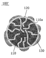
- FIG. 3B is a schematic cross-sectional view of a positive electrode material according to an embodiment of the present invention.
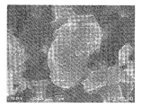
- FIG. 4A is an observation image of the powder particles of the sulfur-containing positive electrode material obtained in Example 1 by a scanning electron microscope (SEM).
- SEM scanning electron microscope
- FIG. 4B is an elemental map of the phosphorus (P) element in the observation image of the cross section of the conductive material by TEM-EDX in the sulfur-containing positive electrode material obtained in Example 1.
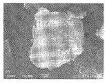
- FIG. 5A is an observation image of the powder particles of the sulfur-containing positive electrode material obtained in Comparative Example 1 by a scanning electron microscope (SEM).
- FIG. 5B is an elemental map of the phosphorus (P) element in the observation image of the cross section of the conductive material by TEM-EDX in the sulfur-containing positive electrode material obtained in Comparative Example 1.
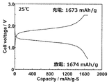
- FIG. 6 is a charge / discharge curve for the test cell (all-solid-state lithium-ion secondary battery) produced in Example 2.
- the present invention will be described by taking as an example a laminated type (internal parallel connection type) all-solid-state lithium secondary battery, which is a form of a secondary battery.
- the solid electrolyte constituting the all-solid-state lithium secondary battery is a material mainly composed of an ionic conductor capable of ionic conduction in a solid.
- the all-solid-state lithium secondary battery has an advantage that various problems caused by the flammable organic electrolytic solution do not occur in principle unlike the conventional liquid-based lithium secondary battery.
- the use of a high-potential, large-capacity positive electrode material and a large-capacity negative electrode material has the advantage that the output density and energy density of the battery can be significantly improved.
- One embodiment of the present invention includes a conductive material having pores, a solid electrolyte, and a positive electrode active material containing sulfur, and at least a part of the solid electrolyte and at least a part of the positive electrode active material are in contact with each other. It is a positive electrode material for an electric device, which is arranged on the inner surface of the pores as described above. According to the positive electrode material for an electric device according to the present embodiment, the capacity characteristics and the charge / discharge rate characteristics of an electric device such as an all-solid-state lithium ion secondary battery are improved despite the use of a positive electrode active material containing sulfur. be able to.
- FIG. 1 is a perspective view showing the appearance of a flat laminated all-solid-state lithium-ion secondary battery according to an embodiment of the lithium-ion secondary battery according to the present invention.
- FIG. 2 is a cross-sectional view taken along line 2-2 shown in FIG. By making it a laminated type, the battery can be made compact and has a high capacity.
- laminated battery hereinafter, also simply referred to as “laminated battery”
- the laminated battery 10a has a rectangular flat shape, and a negative electrode current collector plate 25 and a positive electrode current collector plate 27 for extracting electric power are pulled out from both sides thereof.
- the power generation element 21 is wrapped with a battery exterior material (laminated film 29) of the laminated battery 10a, and the periphery thereof is heat-sealed.
- the power generation element 21 has a negative electrode current collector plate 25 and a positive electrode current collector plate 27 external to the power generation element 21. It is sealed in the state of being pulled out.
- the lithium ion secondary battery according to this embodiment is not limited to a laminated flat battery.
- the wound lithium-ion secondary battery may have a cylindrical shape, or may be formed by deforming such a cylindrical shape into a rectangular flat shape.
- a laminated film may be used for the exterior material, or a conventional cylindrical can (metal can) may be used, and the present invention is not particularly limited.
- the power generation element is housed inside a laminated film containing aluminum. By this form, weight reduction can be achieved.
- the removal of the current collector plates (25, 27) shown in FIG. 1 is not particularly limited.
- the negative electrode current collector plate 25 and the positive electrode current collector plate 27 may be pulled out from the same side, or the negative electrode current collector plate 25 and the positive electrode current collector plate 27 may be divided into a plurality of parts and taken out from each side. It is not limited to what is shown in FIG. 1, such as good.
- the terminal in the winding type lithium ion battery, the terminal may be formed by using, for example, a cylindrical can (metal can) instead of the tab.
- the laminated battery 10a of the present embodiment has a structure in which a flat, substantially rectangular power generation element 21 in which a charge / discharge reaction actually proceeds is sealed inside a laminated film 29 which is a battery exterior material.
- the power generation element 21 has a configuration in which a positive electrode, a solid electrolyte layer 17, and a negative electrode are laminated.
- the positive electrode has a structure in which the positive electrode active material layer 15 containing the positive electrode active material is arranged on both sides of the positive electrode current collector 11 ′′.
- the negative electrode is a negative electrode containing the negative electrode active material on both sides of the negative electrode current collector 11 ′. It has a structure in which the active material layer 13 is arranged.
- one positive electrode active material layer 15 and the negative electrode active material layer 13 adjacent thereto are opposed to each other via the solid electrolyte layer 17.
- the positive electrode, the solid electrolyte layer, and the negative electrode are laminated in this order.
- the adjacent positive electrode, the solid electrolyte layer, and the negative electrode constitute one cell cell layer 19. Therefore, the laminated battery 10a shown in FIG. 1 is It can be said that a plurality of cell cell layers 19 are laminated so as to have a configuration in which they are electrically connected in parallel.
- the negative electrode active material layer 13 is arranged on only one side, but the active material layers are provided on both sides. May be done. That is, instead of using a current collector dedicated to the outermost layer having an active material layer on only one side, a current collector having active material layers on both sides may be used as it is as a current collector for the outermost layer. Further, in some cases, the negative electrode active material layer 13 and the positive electrode active material layer 15 may be used as the negative electrode and the positive electrode, respectively, without using the current collector (11', 11 ").
- the negative electrode current collector 11'and the positive electrode current collector 11' are attached with a negative electrode current collector plate (tab) 25 and a positive electrode current collector plate (tab) 27 that are conductive to each electrode (positive electrode and negative electrode), respectively, and the battery exterior. It has a structure that is led out to the outside of the laminated film 29 so as to be sandwiched between the ends of the laminated film 29, which is a material.
- the positive electrode current collector plate 27 and the negative electrode current collector plate 25 are positive electrodes, if necessary. It may be attached to the positive electrode current collector 11 "and the negative electrode current collector 11'of each electrode by ultrasonic welding, resistance welding, or the like via a lead and a negative electrode lead (not shown).
- the current collector has a function of mediating the movement of electrons from the electrode active material layer.
- the materials that make up the current collector There are no particular restrictions on the materials that make up the current collector.
- a constituent material of the current collector for example, a metal or a resin having conductivity can be adopted.
- examples of the metal include aluminum, nickel, iron, stainless steel, titanium, and copper.
- a clad material of nickel and aluminum, a clad material of copper and aluminum, and the like may be used.
- the foil may be a metal surface coated with aluminum.
- aluminum, stainless steel, copper, and nickel are preferable from the viewpoints of electron conductivity, battery operating potential, adhesion of the negative electrode active material by sputtering to the current collector, and the like.
- examples of the latter resin having conductivity include a resin in which a conductive filler is added to a non-conductive polymer material as needed.
- non-conductive polymer material examples include polyethylene (PE; high density polyethylene (HDPE), low density polyethylene (LDPE), etc.), polypropylene (PP), polyethylene terephthalate (PET), polyether nitrile (PEN), and polyimide.
- PE polyethylene
- HDPE high density polyethylene
- LDPE low density polyethylene
- PP polypropylene
- PET polyethylene terephthalate
- PEN polyether nitrile
- PI Polyimide
- PAI Polypropylene
- PA Polytetrafluoroethylene
- SBR Styrene-butadiene rubber
- PAN Polyacrylonitrile
- PMA Polymethylacrylate
- PMMA Polymethylmethacrylate
- PVC Polyvinyl chloride
- PVdF polyvinylidene fluoride
- PS polystyrene
- Such non-conductive polymer materials may have excellent potential or solvent resistance.
- a conductive filler may be added to the above-mentioned conductive polymer material or non-conductive polymer material as needed.
- a conductive filler is inevitably indispensable in order to impart conductivity to the resin.
- the conductive filler can be used without particular limitation as long as it is a conductive substance.
- materials having excellent conductivity, potential resistance, or lithium ion blocking property include metals and conductive carbon.
- the metal is not particularly limited, and includes at least one metal selected from the group consisting of Ni, Ti, Al, Cu, Pt, Fe, Cr, Sn, Zn, In, and Sb, or at least one of these metals. It preferably contains an alloy or metal oxide.
- the conductive carbon is not particularly limited.
- acetylene black is selected from the group consisting of acetylene black, vulcan (registered trademark), black pearl (registered trademark), carbon nanofiber, Ketjen black (registered trademark), carbon nanotube, carbon nanohorn, carbon nanoballoon, and fullerene. It contains at least one species.
- the amount of the conductive filler added is not particularly limited as long as it can impart sufficient conductivity to the current collector, and is generally 5 to 80% by mass with respect to 100% by mass of the total mass of the current collector. Is.
- the current collector may have a single-layer structure made of a single material, or may have a laminated structure in which layers made of these materials are appropriately combined. From the viewpoint of reducing the weight of the current collector, it is preferable to include a conductive resin layer made of at least a conductive resin. Further, from the viewpoint of blocking the movement of lithium ions between the cells of the cell, a metal layer may be provided on a part of the current collector. Further, if the negative electrode active material layer and the positive electrode active material layer, which will be described later, have conductivity by themselves and can exhibit the current collecting function, a current collector as a member different from these electrode active material layers is used. It doesn't have to be. In such a form, the negative electrode active material layer described later constitutes the negative electrode as it is, and the positive electrode active material layer described later constitutes the positive electrode as it is.
- the negative electrode active material layer 13 contains a negative electrode active material.
- the type of the negative electrode active material is not particularly limited, and examples thereof include a carbon material, a metal oxide, and a metal active material.
- the carbon material include natural graphite, artificial graphite, mesocarbon microbeads (MCMB), highly oriented graphite (HOPG), hard carbon, soft carbon and the like.
- the metal oxide include Nb 2 O 5 and Li 4 Ti 5 O 12 .
- a silicon-based negative electrode active material or a tin-based negative electrode active material may be used.
- silicon and tin belong to Group 14 elements and are known to be negative electrode active materials that can greatly improve the capacity of a non-aqueous electrolyte secondary battery. Since these simple substances can occlude and release a large number of charge carriers (lithium ions, etc.) per unit volume (mass), they are high-capacity negative electrode active materials.
- Si alone as the silicon-based negative electrode active material.
- a silicon oxide such as SiO x (0.3 ⁇ x ⁇ 1.6) disproportionated into two phases, a Si phase and a silicon oxide phase.
- the range of x is more preferably 0.5 ⁇ x ⁇ 1.5, and further preferably 0.7 ⁇ x ⁇ 1.2.
- a silicon-containing alloy silicon-containing alloy-based negative electrode active material
- examples of the negative electrode active material containing a tin element include Sn alone, tin alloys (Cu—Sn alloys, Co—Sn alloys), amorphous tin oxides, tin silicon oxides and the like. Of these, SnB 0.4 P 0.6 O 3.1 is exemplified as the amorphous tin oxide. Further, SnSiO 3 is exemplified as the tin silicon oxide.
- a metal containing lithium may be used as the negative electrode active material.
- a negative electrode active material is not particularly limited as long as it is a lithium-containing active material, and examples thereof include metallic lithium and lithium-containing alloys.
- the lithium-containing alloy include alloys of Li and at least one of In, Al, Si and Sn.
- two or more kinds of negative electrode active materials may be used in combination.
- a negative electrode active material other than the above may be used.
- the negative electrode active material preferably contains metallic lithium, a silicon-based negative electrode active material, or a tin-based negative electrode active material, and particularly preferably contains metallic lithium.
- the shape of the negative electrode active material examples include particulate (spherical and fibrous) and thin film.
- its average particle size (D 50 ) is preferably in the range of, for example, 1 nm to 100 ⁇ m, more preferably in the range of 10 nm to 50 ⁇ m, and further preferably in the range of 100 nm. It is in the range of ⁇ 20 ⁇ m, and particularly preferably in the range of 1 to 20 ⁇ m.
- the value of the average particle size (D 50 ) of the active material can be measured by the laser diffraction / scattering method.
- the content of the negative electrode active material in the negative electrode active material layer is not particularly limited, but is preferably in the range of, for example, 40 to 99% by mass, and preferably in the range of 50 to 90% by mass. More preferred.
- the negative electrode active material layer preferably further contains a solid electrolyte. Since the negative electrode active material layer contains a solid electrolyte, the ionic conductivity of the negative electrode active material layer can be improved.
- the solid electrolyte include a sulfide solid electrolyte and an oxide solid electrolyte, and a sulfide solid electrolyte is preferable.
- Examples of the sulfide solid electrolyte include LiI-Li 2 S-SiS 2 , LiI-Li 2 S-P 2 O 5 , LiI-Li 3 PO 4 -P 2 S 5 , Li 2 S-P 2 S 5 , and Li 2 S-P 2 S 5.
- the sulfide solid electrolyte may have, for example, a Li 3 PS 4 skeleton, a Li 4 P 2 S 7 skeleton, or a Li 4 P 2 S 6 skeleton. ..
- Examples of the sulfide solid electrolyte having a Li 3 PS 4 skeleton include LiI-Li 3 PS 4 , LiI-LiBr-Li 3 PS 4, and Li 3 PS 4 .
- Examples of the sulfide solid electrolyte having a Li 4 P 2 S 7 skeleton include a Li-PS-based solid electrolyte called LPS (for example, Li 7 P 3 S 11 ).
- the sulfide solid electrolyte for example, LGPS represented by Li (4-x) Ge (1-x) P x S 4 (x satisfies 0 ⁇ x ⁇ 1) may be used.
- the sulfide solid electrolyte contained in the active material layer is preferably a sulfide solid electrolyte containing P element, and the sulfide solid electrolyte is a material containing Li 2 SP 2 S 5 as a main component. It is more preferable to have.
- the sulfide solid electrolyte may contain halogen (F, Cl, Br, I).
- the sulfide solid electrolyte comprises Li 6 PS 5 X, where X is Cl, Br or I, preferably Cl.
- the sulfide solid electrolyte may be sulfide glass, crystallized sulfide glass, or a crystalline material obtained by the solid phase method.
- the sulfide glass can be obtained, for example, by performing mechanical milling (ball mill or the like) on the raw material composition.
- the crystallized sulfide glass can be obtained, for example, by heat-treating the sulfide glass at a temperature equal to or higher than the crystallization temperature.
- the ionic conductivity (for example, Li ionic conductivity) of the sulfide solid electrolyte at room temperature (25 ° C.) is preferably 1 ⁇ 10 -5 S / cm or more, for example, 1 ⁇ 10 -4 S / cm. It is more preferably cm or more.
- the value of the ionic conductivity of the solid electrolyte can be measured by the AC impedance method.
- Examples of the oxide solid electrolyte include compounds having a NASICON type structure and the like.
- a compound having a NASION type structure a compound (LAGP) represented by the general formula Li 1 + x Al x Ge 2-x (PO 4 ) 3 (0 ⁇ x ⁇ 2), a general formula Li 1 + x Al x Ti 2
- LAGP a compound represented by the general formula Li 1 + x Al x Ge 2-x (PO 4 ) 3 (0 ⁇ x ⁇ 2)
- a general formula Li 1 + x Al x Ti 2 examples thereof include a compound (LATP) represented by ⁇ x (PO 4 ) 3 (0 ⁇ x ⁇ 2).
- LiLaTIO for example, Li 0.34 La 0.51 TiO 3
- LiPON for example, Li 2.9 PO 3.3 N 0.46
- LiLaZrO for example, LiLaZrO
- the shape of the solid electrolyte examples include a particle shape such as a true spherical shape and an elliptical spherical shape, and a thin film shape.
- its average particle size (D 50 ) is not particularly limited, but is preferably 40 ⁇ m or less, more preferably 20 ⁇ m or less, still more preferably 10 ⁇ m or less.
- the average particle size (D 50 ) is preferably 0.01 ⁇ m or more, and more preferably 0.1 ⁇ m or more.
- the content of the solid electrolyte in the negative electrode active material layer is, for example, preferably in the range of 1 to 60% by mass, and more preferably in the range of 10 to 50% by mass.
- the negative electrode active material layer may further contain at least one of a conductive auxiliary agent and a binder in addition to the negative electrode active material and the solid electrolyte described above.
- the conductive auxiliary agent examples include metals such as aluminum, stainless steel (SUS), silver, gold, copper and titanium, alloys or metal oxides containing these metals; carbon fiber (specifically, vapor-grown carbon fiber). (VGCF), polyacrylonitrile-based carbon fiber, pitch-based carbon fiber, rayon-based carbon fiber, activated carbon fiber, etc.), carbon nanotube (CNT), carbon black (specifically, acetylene black, Ketjen black (registered trademark)) , Furness black, channel black, thermal lamp black, etc.), but is not limited to these. Further, a particulate ceramic material or a resin material coated with the above metal material by plating or the like can also be used as a conductive auxiliary agent.
- metals such as aluminum, stainless steel (SUS), silver, gold, copper and titanium, alloys or metal oxides containing these metals
- carbon fiber specifically, vapor-grown carbon fiber). (VGCF), polyacrylonitrile-based carbon fiber, pitch-based carbon fiber, rayon-based carbon fiber, activate
- these conductive auxiliaries from the viewpoint of electrical stability, it is preferable to contain at least one selected from the group consisting of aluminum, stainless steel, silver, gold, copper, titanium, and carbon, and aluminum, stainless steel. It is more preferable to contain at least one selected from the group consisting of silver, gold, and carbon, and even more preferably to contain at least one carbon. Only one kind of these conductive auxiliary agents may be used alone, or two or more kinds thereof may be used in combination.
- the shape of the conductive auxiliary agent is preferably particulate or fibrous.
- the shape of the particles is not particularly limited, and may be any shape such as powder, sphere, rod, needle, plate, columnar, indefinite, fluffy, and spindle-shaped. It doesn't matter.
- the average particle size (primary particle size) when the conductive auxiliary agent is in the form of particles is not particularly limited, but is preferably 0.01 to 10 ⁇ m from the viewpoint of the electrical characteristics of the battery.
- the "particle diameter of the conductive auxiliary agent” means the maximum distance L among the distances between arbitrary two points on the contour line of the conductive auxiliary agent.
- the particle size of the particles observed in several to several tens of fields using an observation means such as a scanning electron microscope (SEM) or a transmission electron microscope (TEM). The value calculated as the average value of is adopted.
- the content of the conductive auxiliary agent in the negative electrode active material layer is not particularly limited, but is preferably 0 to 10% by mass with respect to the total mass of the negative electrode active material layer. , More preferably 2 to 8% by mass, still more preferably 4 to 7% by mass. Within such a range, it is possible to form a stronger electron conduction path in the negative electrode active material layer, and it is possible to effectively contribute to the improvement of battery characteristics.
- the binder is not particularly limited, and examples thereof include the following materials.
- Fluororesin such as ethylene / tetrafluoroethylene copolymer (ETFE), polychlorotrifluoroethylene (PCTFE), ethylene / chlorotrifluoroethylene copolymer (ECTFE), polyvinylfluorovinyl (PVF), vinylidene fluoride- Hexafluoropropylene-based fluororubber (VDF-HFP-based fluororubber), vinylidene fluoride-hexafluoropropylene-tetrafluoroethylene-based fluororubber (VDF-HFP-TFE-based fluororubber), vinylidene fluoride-pentafluoropropylene-based fluororubber (VDF-PFP-based fluorubber), vinylidene fluoride-pentafluoropropylene-tetrafluoroethylene-based fluororubber (VDF-PFP-TFE-based fluorubber), vinylidene fluoride-p
- the thickness of the negative electrode active material layer varies depending on the configuration of the target secondary battery, but is preferably in the range of 0.1 to 1000 ⁇ m, for example.
- the solid electrolyte layer is a layer interposed between the above-mentioned positive electrode active material layer and the negative electrode active material layer and essentially containing the solid electrolyte.
- the specific form of the solid electrolyte contained in the solid electrolyte layer is not particularly limited, and the solid electrolyte exemplified in the column of the negative electrode active material layer and its preferred form can be similarly adopted. In some cases, a solid electrolyte other than the above-mentioned solid electrolyte may be used in combination.
- the solid electrolyte layer may further contain a binder in addition to the predetermined solid electrolyte described above.
- a binder in addition to the predetermined solid electrolyte described above.
- the binder that can be contained in the solid electrolyte layer the examples and preferred forms described in the column of the negative electrode active material layer can be similarly adopted.
- the thickness of the solid electrolyte layer varies depending on the configuration of the target lithium ion secondary battery, but is preferably 600 ⁇ m or less, more preferably 500 ⁇ m or less, from the viewpoint of improving the volumetric energy density of the battery. , More preferably 400 ⁇ m or less.
- the lower limit of the thickness of the solid electrolyte layer is not particularly limited, but is preferably 1 ⁇ m or more, more preferably 5 ⁇ m or more, and further preferably 10 ⁇ m or more.
- the positive electrode active material layer contains the positive electrode material for an electric device according to one embodiment of the present invention.
- the positive electrode material for an electric device includes a conductive material having pores, a solid electrolyte, and a positive electrode active material containing sulfur.
- the type of the positive electrode active material containing sulfur is not particularly limited, and examples thereof include particles or thin films of an organic sulfur compound or an inorganic sulfur compound in addition to elemental sulfur (S), which can be charged by utilizing the oxidation-reduction reaction of sulfur. Any substance may be used as long as it can release lithium ions at times and can store lithium ions at the time of discharge.
- the organic sulfur compound include a disulfide compound, a sulfur-modified polyacrylonitrile represented by the compound described in International Publication No. 2010/0444437, a sulfur-modified polyisoprene, rubianic acid (dithiooxamide), and polysulfide carbon.
- disulfide compounds sulfur-modified polyacrylonitrile, and rubianic acid are preferable, and sulfur-modified polyacrylonitrile is particularly preferable.
- the disulfide compound a compound having a dithiobiurea derivative, a thiourea group, a thioisocyanate, or a thioamide group is more preferable.
- the sulfur-modified polyacrylonitrile is a modified polyacrylonitrile containing a sulfur atom, which is obtained by mixing sulfur powder and polyacrylonitrile and heating them under an inert gas or under reduced pressure.
- the estimated structure is, for example, Chem. Mater.
- the polyacrylonitrile is ring-closed to form a polycyclic structure, and at least a part of S is bound to C.
- the compounds described in this document have strong peak signals near 1330 cm -1 and 1560 cm -1 in Raman spectra, and peaks near 307 cm -1 , 379 cm -1 , 472 cm -1 , and 929 cm -1 . do.
- inorganic sulfur compounds are preferable because they are excellent in stability.
- S, S-carbon composite, TiS 2 , TiS 3 , TiS 4 , FeS 2 and MoS 2 are preferable, and elemental sulfur (S), TiS 2 and FeS 2 are more preferable, and from the viewpoint of high capacity.
- Elementary sulfur (S) is particularly preferred.
- As the elemental sulfur (S), ⁇ -sulfur, ⁇ -sulfur, or ⁇ -sulfur having an S8 structure can be used.
- the positive electrode material according to this embodiment may further contain a positive electrode active material containing no sulfur in addition to the positive electrode active material containing sulfur.
- the sulfur-free positive electrode active material include layered rock salt type active materials such as LiCoO 2 , LiMnO 2 , LiNiO 2 , LiVO 2 , and Li (Ni-Mn-Co) O 2 , LiMn 2 O 4 , LiNi 0. 5
- spinel-type active materials such as Mn 1.5 O 4
- olivine-type active materials such as LiFePO 4 and LiMnPO 4
- Si-containing active materials such as Li 2 FeSiO 4 and Li 2 MnSiO 4 .
- the oxide active material other than the above include Li 4 Ti 5 O 12 .
- two or more kinds of positive electrode active materials may be used in combination.
- a positive electrode active material other than the above may be used.
- the ratio of the content of the positive electrode active material containing sulfur to 100% by mass of the total amount of the positive electrode active material is preferably 50% by mass or more, more preferably 70% by mass or more, and further preferably 80% by mass.
- the above is more preferably 90% by mass or more, particularly preferably 95% by mass or more, and most preferably 100% by mass.
- the positive electrode material according to this embodiment indispensably contains a solid electrolyte.
- the specific form of the solid electrolyte contained in the positive electrode material according to the present embodiment is not particularly limited, and the solid electrolyte exemplified in the column of the negative electrode active material layer and its preferred form can be similarly adopted. In some cases, a solid electrolyte other than the above-mentioned solid electrolyte may be used in combination.
- the solid electrolyte contained in the positive electrode material according to this embodiment is preferably a sulfide solid electrolyte.
- the solid electrolyte contained in the solid electrolyte layer contains alkali metal atoms.
- the alkali metal that can be contained in the solid electrolyte include Li, Na, and K, and Li is particularly preferable because it has excellent ionic conductivity.
- the solid electrolyte layer contained in the solid electrolyte layer contains alkali metal atoms (eg, Li, Na or K; preferably Li) and phosphorus and / or boron atoms.
- Examples of the sulfide solid electrolyte containing such an alkali metal atom and a phosphorus atom and / or a boron atom include LiI-Li 2 SP 2 O 5 and LiI-Li 3 PO 4 -P 2 S 5 .
- Li 2 SP 2 S 5 LiI-Li 3 PS 4 , LiI-LiBr-Li 3 PS 4, Li 3 PS 4, Li 2 SP 2 S 5 , Li 2 SP 2 S 5 -LiI , Li 2 S-P 2 S 5 -Li 2 O, Li 2 S-P 2 S 5 -Li 2 O-Li I, Li 2 S-SiS 2 -B 2 S 3 -Li I, Li 2 S-SiS 2- P 2 S 5 -LiI, Li 2 SB 2 S 3 , Li 2 S-P 2 S 5 -Z m Sn (where m and n are positive numbers, Z is Ge, Zn, Ga ), Li 2 S-SiS 2 -Li 3 PO 4 , and the like.
- the sulfide solid electrolyte having a Li 4 P 2 S 7 skeleton examples include a Li-PS-based solid electrolyte called LPS (for example, Li 7 P 3 S 11 ). Further, for example, LGPS represented by Li (4-x) Ge (1-x) P x S 4 (x satisfies 0 ⁇ x ⁇ 1) may be used.
- the sulfide solid electrolyte contained in the active material layer is preferably a sulfide solid electrolyte containing a phosphorus atom, and the sulfide solid electrolyte is a material containing Li 2 SP 2 S 5 as a main component. It is more preferable to have.
- the sulfide solid electrolyte may contain halogen (F, Cl, Br, I).
- the sulfide solid electrolyte comprises Li 6 PS 5 X, where X is Cl, Br or I, preferably Cl. Since these solid electrolytes have high ionic conductivity, they can effectively contribute to the manifestation of the effects of the present invention.
- the positive electrode material according to this embodiment indispensably contains a conductive material having pores.
- the specific form of the conductive material contained in the positive electrode material according to this embodiment is not particularly limited as long as it has pores, and conventionally known materials can be appropriately adopted. From the viewpoint of excellent conductivity, easy processing, and easy design of a desired pore distribution, the conductive material having pores is preferably a carbon material.
- Examples of the carbon material having pores include activated carbon, Ketjen black (registered trademark) (highly conductive carbon black), (oil) furnace black, channel black, acetylene black, thermal black, and carbon black such as lamp black. Examples thereof include carbon particles (carbon carriers) made of coke, natural graphite, artificial graphite and the like.
- the main component of the carbon material is preferably carbon.
- the main component is carbon means that carbon atoms are contained as the main component, and is a concept including both carbon atoms and substantially carbon atoms.
- “Substantially composed of carbon atoms” means that impurities of about 2 to 3% by mass or less can be mixed.
- the BET specific surface area of the conductive material having pores is preferably 200 m 2 / g or more, more preferably 500 m 2 / g or more, and more preferably 800 m 2 / g or more. Is more preferable, and 1200 m 2 / g or more is particularly preferable, and 1500 m 2 / g or more is most preferable.
- the pore volume of the conductive material having pores (preferably a carbon material) is preferably 1.0 mL / g or more, more preferably 1.3 mL / g or more, and 1.5 mL / g. It is more preferably g or more.
- the values of the BET specific surface area and the pore volume of the conductive material can be measured by nitrogen adsorption / desorption measurement. This nitrogen adsorption / desorption measurement is carried out using BELSORP mini manufactured by Microtrac Bell Co., Ltd., and is carried out by a multi-point method at a temperature of -196 ° C.
- the BET specific surface area is obtained from the adsorption isotherm in the range of relative pressure of 0.01 ⁇ P / P 0 ⁇ 0.05.
- the pore volume is determined from the volume of adsorption N 2 at a relative pressure of 0.96.
- the average pore diameter of the conductive material is not particularly limited, but is preferably 50 nm or less, and particularly preferably 30 nm or less. If the average pore diameter of the conductive material is within these ranges, sufficient electrons can be transferred to the active material of the positive electrode containing sulfur arranged inside the pores, which is located away from the pore wall. Can be supplied.
- the value of the average pore diameter of the conductive material can be calculated by nitrogen adsorption / desorption measurement in the same manner as in the case of obtaining the values of the BET specific surface area and the pore volume.
- the average particle size (primary particle size) when the conductive material is in the form of particles is not particularly limited, but is preferably 0.05 to 50 ⁇ m, more preferably 0.1 to 20 ⁇ m. , 0.5 to 10 ⁇ m, more preferably.
- the conductive auxiliary agent described above is similarly adopted.
- the positive electrode material according to this embodiment contains a conductive material having pores, a solid electrolyte, and a positive electrode active material containing sulfur, but at least a part of the solid electrolyte and at least a part of the positive electrode activity. It is characterized in that the substances are arranged on the inner surface of the pores of the conductive material so as to be in contact with each other.
- FIG. 3A is a schematic cross-sectional view of the positive electrode material 100'in the prior art.
- FIG. 3B is a schematic cross-sectional view of the positive electrode material 100 according to the embodiment of the present invention.
- the carbon material (for example, activated carbon) 110 which is a conductive material, has a large number of pores 110a.
- Sulfur 120 which is a positive electrode active material, is filled and arranged inside the pores 110a.
- the positive electrode active material (sulfur) 120 is also arranged on the surface of the carbon material (activated carbon) 110.
- the positive electrode material 100' accordinging to the prior art shown in FIG.
- the solid electrolyte 130 is arranged only on the surface of the carbon material (activated carbon) 110. There is. On the other hand, in the positive electrode material 100 according to the embodiment of the present invention shown in FIG. 3B, the solid electrolyte (for example, Li 6 PS 5 Cl, which is a sulfide solid electrolyte) 130 is only on the surface of the carbon material (activated carbon) 110. Instead, it is also arranged on the inner surface of the pores of the carbon material (activated carbon) 110.
- a continuous phase made of the positive electrode active material (sulfur) 120 is filled inside the pores 110a, and the solid electrolyte 130 is arranged as a dispersed phase in the continuous phase.
- the solid electrolyte arranged on the inner surface of the pores and at least a part of the positive electrode active material (sulfur) similarly arranged inside the pores are in contact with each other.
- elemental mapping derived from each material is performed using energy dispersive X-ray spectroscopy (EDX) on an observation image of a cross section of a conductive material using a transmission electron microscope (TEM), and the obtained element map and all elements are used. It is possible to confirm the arrangement form of each material by using the count number of the element derived from each material as an index with respect to the count number (see Examples described later). For example, if the solid electrolyte contains a phosphorus atom and / or a boron atom and the phosphorus atom and / or the boron atom cannot be derived from another material, the above element for phosphorus and / or boron.
- EDX energy dispersive X-ray spectroscopy
- TEM transmission electron microscope
- the value of the ratio is preferably 0.15 or more, more preferably 0.20 or more, still more preferably 0.26 or more, and particularly preferably 0.35 or more.
- the preferable upper limit of the value of the ratio is not particularly limited, but as an example of the preferable upper limit, it is 0.50 or less, and more preferably 0.45 or less.
- the capacity characteristics and the charge / discharge rate characteristics are improved in an electric device such as an all-solid-state lithium ion secondary battery using a positive electrode active material containing sulfur. Is possible. Although the mechanism by which such an excellent effect is obtained by the configuration according to this embodiment has not been completely clarified, the following mechanism has been presumed. That is, in order for the charge / discharge reaction to proceed in the positive electrode active material containing sulfur, it is necessary that charge carriers such as electrons and lithium ions proceed smoothly in and out of the surface of the positive electrode active material.
- the positive electrode active material (sulfur) 120 when the positive electrode active material (sulfur) 120 is held inside the pores 110a of the conductive material such as the carbon material 110 as in the positive electrode material 100'shown in FIG. 3A, it is located deep in the pores 110a. On the surface of the positive electrode active material (sulfur) 120, electrons can flow in and out smoothly to some extent through the conductive material. However, since the solid electrolyte 130 is not arranged inside the pores 110a, charge carriers such as lithium ions smoothly move in and out on the surface of the positive electrode active material (sulfur) 120 located deep inside the pores 110a. do not. As a result, in the positive electrode active material (sulfur) 120 located deep in the pores 110a, the charge / discharge reaction does not proceed sufficiently, and it is considered that problems such as deterioration of capacity characteristics and charge / discharge rate characteristics occur.
- the solid electrolyte 130 is held together with the positive electrode active material (sulfur) 120 on the inner surface of the pores 110a of the conductive material such as the carbon material 110 as in the positive electrode material 100 shown in FIG. 3B, the pores.
- the positive electrode active material (sulfur) 120 located deep in 110a not only the inflow and outflow of electrons through the conductive material but also the inflow and outflow of charge carriers via the solid electrolyte 130 can proceed smoothly.
- the method for producing the positive electrode material according to the present embodiment having the above configuration is not particularly limited, but an example of the production method will be briefly described.
- a solution in which a solid electrolyte is dissolved in an organic solvent is prepared, and a conductive material is dispersed therein to obtain a dispersion liquid.
- heat treatment is performed at a temperature of about 150 to 250 ° C. for about 1 to 5 hours.
- a conductive material in which the pores of the conductive material are impregnated with the solid electrolyte can be obtained.
- the obtained conductive material is mixed with the positive electrode active material in a dry manner, and further heat-treated under the same conditions as described above.
- the positive electrode active material is melted and permeates into the pores of the conductive material, and a composite material in which the positive electrode active material is arranged (filled) together with the solid electrolyte is obtained inside the pores of the conductive material.
- the composite material thus obtained may be used as it is as a positive electrode material, but a solid electrolyte may be further added to the composite material and mixed, and if necessary, treated with an apparatus such as a ball mill to obtain a positive electrode. It is preferable to obtain the material.
- the content of the positive electrode active material in the positive electrode active material layer is not particularly limited, but is preferably in the range of, for example, 35 to 99% by mass, and preferably in the range of 40 to 90% by mass. More preferred. The value of this content shall be calculated based on the mass of only the positive electrode active material excluding the conductive material and the solid electrolyte.
- the positive electrode active material layer may further contain a conductive auxiliary agent (one that does not retain the positive electrode active material or the solid electrolyte inside the pores) and / or a binder, and the specific form and preferable form thereof may be further contained.
- a conductive auxiliary agent one that does not retain the positive electrode active material or the solid electrolyte inside the pores
- the positive electrode active material layer preferably further contains a solid electrolyte, and particularly preferably a sulfide solid electrolyte.
- the specific form and preferable form of the solid electrolyte such as the sulfide solid electrolyte
- those described in the above-mentioned column of the negative electrode active material layer can be similarly adopted.
- the material constituting the current collector plates (25, 27) is not particularly limited, and known highly conductive materials conventionally used as current collector plates for secondary batteries can be used.
- As the constituent material of the current collector plate for example, metal materials such as aluminum, copper, titanium, nickel, stainless steel (SUS), and alloys thereof are preferable. From the viewpoint of light weight, corrosion resistance, and high conductivity, aluminum and copper are more preferable, and aluminum is particularly preferable.
- the same material may be used for the positive electrode current collector plate 27 and the negative electrode current collector plate 25, or different materials may be used.
- the current collector (11', 11 ") and the current collector plate (25, 27) may be electrically connected to each other via a positive electrode lead or a negative electrode lead.
- a material used in a known lithium ion secondary battery can be similarly adopted.
- the portion taken out from the exterior may come into contact with peripheral devices, wiring, etc. and leak electricity. It is preferable to cover the product with a heat-resistant insulating tube or the like so as not to affect the product (for example, automobile parts, particularly electronic devices, etc.).
- Battery exterior material As the battery exterior material, a known metal can case can be used, and a bag-shaped case using a laminated film 29 containing aluminum, which can cover the power generation element as shown in FIGS. 1 and 2, is used. Can be done.
- the laminated film for example, a laminated film having a three-layer structure in which PP, aluminum, and nylon are laminated in this order can be used, but the laminated film is not limited thereto.
- a laminated film is desirable from the viewpoint of high output, excellent cooling performance, and suitable use for batteries for large equipment for EVs and HEVs. Further, since the group pressure applied to the power generation element from the outside can be easily adjusted, a laminated film containing aluminum is more preferable for the exterior body.
- the laminated battery according to this embodiment has a configuration in which a plurality of single battery layers are connected in parallel, so that it has a high capacity and excellent cycle durability. Therefore, the laminated battery according to this embodiment is suitably used as a driving power source for EVs and HEVs.
- the present invention is not limited to the configuration described in the above-described embodiment, and may be appropriately modified based on the description of the claims. It is possible.
- a positive electrode active material layer electrically bonded to one surface of the current collector and an electrical charge to the opposite surface of the current collector are used.
- a bipolar type battery including a bipolar type electrode having a negative electrode active material layer coupled to the above can also be mentioned.
- the secondary battery according to this embodiment does not have to be an all-solid-state type. That is, the solid electrolyte layer may further contain a conventionally known liquid electrolyte (electrolyte solution).
- the amount of the liquid electrolyte (electrolyte solution) that can be contained in the solid electrolyte layer is not particularly limited, but the shape of the solid electrolyte layer formed by the solid electrolyte is maintained and the liquid electrolyte (electrolyte solution) does not leak. Is preferably the amount of.
- the liquid electrolyte (electrolyte solution) that can be used has a form in which a lithium salt is dissolved in an organic solvent.
- organic solvent used include dimethyl carbonate (DMC), diethyl carbonate (DEC), dipropyl carbonate (DPC), ethyl methyl carbonate (EMC), methyl propionate (MP), methyl acetate (MA), and methyl formate.
- the organic solvent is preferably a chain carbonate, more preferably diethyl carbonate (DEC), ethyl methyl carbonate (EMC) and dimethyl carbonate (DMC) from the viewpoint of further improving the quick charge property and the output property. It is at least one selected from the group consisting of, and more preferably selected from ethyl methyl carbonate (EMC) and dimethyl carbonate (DMC).
- Lithium salts include Li (FSO 2 ) 2 N (lithium bis (fluorosulfonyl) imide; LiFSI), Li (C 2 F 5 SO 2 ) 2 N, LiPF 6 , LiBF 4 , LiClO 4 , LiAsF 6 , LiCF 3 SO 3 and the like can be mentioned.
- the lithium salt is preferably Li (FSO 2 ) 2N ( LiFSI) from the viewpoint of battery output and charge / discharge cycle characteristics.
- the liquid electrolyte may further contain additives other than the above-mentioned components.
- additives include, for example, ethylene carbonate, vinylene carbonate, methylvinylene carbonate, dimethylvinylene carbonate, phenylvinylene carbonate, diphenylvinylene carbonate, ethylvinylene carbonate, diethylvinylene carbonate, vinylethylene carbonate, 1,2-.
- An assembled battery is configured by connecting a plurality of batteries. More specifically, it is composed of serialization, parallelization, or both by using at least two or more. By serializing and parallelizing, it becomes possible to freely adjust the capacity and voltage.
- a small assembled battery that can be attached and detached by connecting multiple batteries in series or in parallel. Then, by connecting a plurality of small detachable batteries in series or in parallel, a large capacity and a large capacity suitable for a vehicle drive power source or an auxiliary power source that require a high volume energy density and a high volume output density. It is also possible to form an assembled battery having an output (battery module, battery pack, etc.). How many batteries are connected to make an assembled battery, and how many stages of small assembled batteries are stacked to make a large-capacity assembled battery depends on the battery capacity of the vehicle (electric vehicle) to be mounted. It may be decided according to the output.
- a battery or a combined battery consisting of a plurality of these can be mounted on a vehicle.
- a plug-in hybrid electric vehicle having a long EV mileage and an electric vehicle having a long one-charge mileage can be configured by mounting such a battery.
- hybrid vehicles, fuel cell vehicles, electric vehicles (all four-wheeled vehicles (passenger cars, trucks, commercial vehicles such as buses, light vehicles, etc.)) can be used as batteries or a combination of multiple batteries. This is because it becomes a highly reliable automobile with a long life by using it for two-wheeled vehicles (including motorcycles) and three-wheeled vehicles.
- the application is not limited to automobiles, and can be applied to various power sources of other vehicles, for example, moving objects such as trains, and power supplies for mounting such as uninterruptible power supplies. It is also possible to use it as.
- Example 1 Preparation of solid electrolyte impregnated carbon
- cryoplasma focused ion beam processing device Helios G4 PFIB CXe manufactured by Thermo Scientific Co., Ltd., accelerated voltage: 30 kV
- the powder particles of the contained positive electrode material were exfoliated to a thickness of about 100 nm.
- the stripped observation sample is transported to a TEM device (JEOL, multifunction analysis transmission electron microscope JEM-F200, acceleration voltage: 200 kV) without exposure to the atmosphere to check the microstructure and EDX attached to the TEM.
- JEOL multifunction analysis transmission electron microscope JEM-F200, acceleration voltage: 200 kV
- the element map data of the part corresponding to the inside of the particle was acquired by the device (energy dispersive X-ray spectroscopic analyzer, JEOL Dual SDD, acceleration voltage: 200 kV) (EDX mapping characteristic X-ray measurement energy band: 0 to 5 keV). ). From the obtained element map data, the counts of all the elements contained in the particles and the counts of the elements (phosphorus; P) derived only from the solid electrolyte were obtained. As a result, the ratio of the count number of the element (P) derived only from the solid electrolyte to the count number of all elements was 0.35.
- the solid electrolyte is also arranged inside the pores of the conductive material (carbon) together with the sulfur which is the positive electrode active material.
- the observation image of the powder particles of the sulfur-containing positive electrode material thus obtained by a scanning electron microscope (SEM) is shown in FIG. 4A, and the phosphorus (P) element in the observation image of the cross section of the conductive material by TEM-EDX.
- the elemental map for is shown in FIG. 4B.
- test cell all-solid-state lithium-ion secondary battery
- the battery was manufactured in a glove box having an argon atmosphere with a dew point of ⁇ 68 ° C. or lower.
- a positive electrode active material layer having a diameter of 10 mm and a thickness of about 0.06 mm was formed on one side of the solid electrolyte layer by inserting (also serving as a positive electrode current collector) and pressing at a pressure of 300 MPa for 3 minutes.
- a cylindrical convex punch (which also serves as a negative electrode current collector) on the lower side was extracted, and a lithium foil (manufactured by Niraco, 0.20 mm thick) punched to a diameter of 8 mm and an indium foil punched to a diameter of 9 mm (manufactured by Niraco, 0.20 mm) were punched out as a negative electrode.
- Niraco Co., Ltd., thickness 0.30 mm is layered, and the indium foil is inserted from the underside of the cylindrical tube jig so that it is located on the side of the solid electrolyte layer, and the cylindrical convex punch is inserted again, and the pressure is 75 MPa.
- a lithium-indium negative electrode was formed by pressing for 3 minutes.
- test cell all-solid-state lithium ion battery in which a negative electrode current collector (punch), a lithium-indium negative electrode, a solid electrolyte layer, a positive electrode active material layer, and a positive electrode current collector (punch) are laminated in this order.
- a negative electrode current collector punch
- a lithium-indium negative electrode a lithium-indium negative electrode
- a solid electrolyte layer a positive electrode active material layer
- positive electrode current collector punch
- Example 2 In the preparation of the solid electrolyte-impregnated carbon, an all-solid-state lithium-ion secondary battery was produced by the same method as in Example 1 described above, except that the conditions of the vacuum heat treatment after removing the ethanol under reduced pressure were changed to 230 ° C. for 3 hours. bottom.
- the sulfur-containing positive electrode material prepared in this example TEM-EDX was used, and the ratio of the count number of the element (P) derived only from the solid electrolyte to the count number of all elements was the same as above. Was calculated to be 0.26. From this, it was confirmed that in the sulfur-containing positive electrode material according to the present embodiment, the solid electrolyte is also arranged inside the pores of the conductive material (carbon) together with the sulfur which is the positive electrode active material.
- Example 3 In the thermal impregnation of sulfur, sulfur is added to the solid electrolyte impregnated carbon and mixed sufficiently in a Menou dairy pot, and then the mixed powder is vacuum-sealed in a quartz tube at 1 Pa or less in place of a closed pressure-resistant autoclave container for 3 hours at 170 ° C.
- An all-solid-state lithium-ion secondary battery was produced by the same method as in Example 1 described above, except that the sulfur was melted by heating and the solid electrolyte-impregnated carbon was impregnated with the sulfur.
- the sulfur-containing positive electrode material prepared in this example TEM-EDX was used, and the ratio of the count number of the element (P) derived only from the solid electrolyte to the count number of all elements was the same as above. Was calculated to be 0.20. From this, it was confirmed that in the sulfur-containing positive electrode material according to the present embodiment, the solid electrolyte is also arranged inside the pores of the conductive material (carbon) together with the sulfur which is the positive electrode active material.
- Example 4 An all-solid-state lithium-ion secondary battery was produced by the same method as in Example 1 described above, except that the mixing condition by the planetary ball mill was changed to 3 hours at 540 rpm in the preparation of the sulfur-containing positive electrode material.
- the sulfur-containing positive electrode material prepared in this example TEM-EDX was used, and the ratio of the count number of the element (P) derived only from the solid electrolyte to the count number of all elements was the same as above. Was calculated to be 0.12. From this, it was confirmed that in the sulfur-containing positive electrode material according to the present embodiment, the solid electrolyte is also arranged inside the pores of the conductive material (carbon) together with the sulfur which is the positive electrode active material.
- an all-solid-state lithium-ion secondary battery was produced by the same method as in Example 1 described above.
- test cell The capacity characteristics and charge / discharge rate characteristics of each of the above comparative examples and the test cells prepared in each example were evaluated by the following methods. All of the following measurements were performed using a charge / discharge test device (HJ-SD8 manufactured by Hokuto Denko Co., Ltd.) in a constant temperature and constant temperature bath set at 25 ° C.
- HJ-SD8 manufactured by Hokuto Denko Co., Ltd.
- a test cell is installed in a constant temperature bath, and after the cell temperature becomes constant, discharge is performed at a current density of 0.2 mA / cm 2 to a cell voltage of 0.5 V as cell conditioning, and then the same current density is used.
- the 2.5 V constant current constant voltage charge was set to a cutoff current of 0.01 mA / cm 2 .
- the capacity value (mAh / g) per mass of the positive electrode active material was calculated from the value of the charge / discharge capacity obtained after repeating this conditioning charge / discharge cycle 10 times and the mass of the positive electrode active material contained in the positive electrode. The results are shown in Table 1 below. Further, FIG. 6 shows a charge / discharge curve for the test cell (all-solid-state lithium-ion secondary battery) produced in Example 2.
- the charge rate characteristic is 0 with respect to the charge capacity value obtained by constant current charging at 0.05 C with a cut-off voltage of 2.5 V after full discharge by 0.05 C discharge with a cut-off voltage of 0.5 V.
- the percentage (charge rate maintenance rate) of the charge capacity value obtained by constant current charging at .5C was calculated. The results are shown in Table 1 below.
Landscapes
- Chemical & Material Sciences (AREA)
- Chemical Kinetics & Catalysis (AREA)
- Electrochemistry (AREA)
- General Chemical & Material Sciences (AREA)
- Engineering & Computer Science (AREA)
- Manufacturing & Machinery (AREA)
- Materials Engineering (AREA)
- Physics & Mathematics (AREA)
- Condensed Matter Physics & Semiconductors (AREA)
- General Physics & Mathematics (AREA)
- Inorganic Chemistry (AREA)
- Secondary Cells (AREA)
- Battery Electrode And Active Subsutance (AREA)
Priority Applications (5)
| Application Number | Priority Date | Filing Date | Title |
|---|---|---|---|
| US18/033,541 US20230395788A1 (en) | 2020-10-26 | 2020-10-26 | Positive Electrode Material for Electric Device, Positive Electrode for Electric Device and Electric Device Using Positive Electrode Material for Electric Device |
| EP20959660.0A EP4235856A4 (en) | 2020-10-26 | 2020-10-26 | POSITIVE ELECTRODE MATERIAL FOR ELECTRICAL DEVICES, POSITIVE ELECTRODE FOR ELECTRICAL DEVICES THEREOF AND ELECTRICAL DEVICE |
| PCT/IB2020/000884 WO2022090757A1 (ja) | 2020-10-26 | 2020-10-26 | 電気デバイス用正極材料並びにこれを用いた電気デバイス用正極および電気デバイス |
| JP2022558362A JP7493054B2 (ja) | 2020-10-26 | 2020-10-26 | 電気デバイス用正極材料並びにこれを用いた電気デバイス用正極および電気デバイス |
| CN202080106687.0A CN116472629A (zh) | 2020-10-26 | 2020-10-26 | 电气设备用正极材料以及使用了其的电气设备用正极和电气设备 |
Applications Claiming Priority (1)
| Application Number | Priority Date | Filing Date | Title |
|---|---|---|---|
| PCT/IB2020/000884 WO2022090757A1 (ja) | 2020-10-26 | 2020-10-26 | 電気デバイス用正極材料並びにこれを用いた電気デバイス用正極および電気デバイス |
Publications (1)
| Publication Number | Publication Date |
|---|---|
| WO2022090757A1 true WO2022090757A1 (ja) | 2022-05-05 |
Family
ID=81383087
Family Applications (1)
| Application Number | Title | Priority Date | Filing Date |
|---|---|---|---|
| PCT/IB2020/000884 Ceased WO2022090757A1 (ja) | 2020-10-26 | 2020-10-26 | 電気デバイス用正極材料並びにこれを用いた電気デバイス用正極および電気デバイス |
Country Status (5)
| Country | Link |
|---|---|
| US (1) | US20230395788A1 (https=) |
| EP (1) | EP4235856A4 (https=) |
| JP (1) | JP7493054B2 (https=) |
| CN (1) | CN116472629A (https=) |
| WO (1) | WO2022090757A1 (https=) |
Cited By (1)
| Publication number | Priority date | Publication date | Assignee | Title |
|---|---|---|---|---|
| JP2023064505A (ja) * | 2021-10-26 | 2023-05-11 | 日産自動車株式会社 | 正極材料の製造方法 |
Families Citing this family (1)
| Publication number | Priority date | Publication date | Assignee | Title |
|---|---|---|---|---|
| CN117203783A (zh) * | 2021-04-30 | 2023-12-08 | 日产自动车株式会社 | 电气设备用正极材料以及使用其的电气设备用正极和电气设备 |
Citations (9)
| Publication number | Priority date | Publication date | Assignee | Title |
|---|---|---|---|---|
| WO2010044437A1 (ja) | 2008-10-17 | 2010-04-22 | 独立行政法人産業技術総合研究所 | 硫黄変性ポリアクリロニトリル、その製造方法、及びその用途 |
| JP2012041220A (ja) * | 2010-08-17 | 2012-03-01 | Fukuoka Univ | 硫黄複合化活性炭およびその製造方法 |
| WO2012102037A1 (ja) | 2011-01-27 | 2012-08-02 | 出光興産株式会社 | アルカリ金属硫化物と導電剤の複合材料 |
| JP2015088232A (ja) * | 2013-10-28 | 2015-05-07 | ナガセケムテックス株式会社 | 薄膜硫黄被覆活性炭の製造方法、薄膜硫黄被覆活性炭、正極合材及び全固体型リチウム硫黄電池 |
| JP2016127005A (ja) * | 2014-12-31 | 2016-07-11 | 現代自動車株式会社Hyundai Motor Company | 全固体リチウム電池の陽極及びこれを含む二次電池 |
| JP2019040752A (ja) * | 2017-08-25 | 2019-03-14 | 株式会社サムスン日本研究所 | 全固体型二次電池 |
| WO2019078130A1 (ja) * | 2017-10-19 | 2019-04-25 | 三菱瓦斯化学株式会社 | 全固体電池の製造方法 |
| JP2019179604A (ja) * | 2018-03-30 | 2019-10-17 | 東京電力ホールディングス株式会社 | リチウム硫黄固体電池 |
| JP2019179603A (ja) * | 2018-03-30 | 2019-10-17 | 東京電力ホールディングス株式会社 | リチウム硫黄固体電池、電池用正極シート、電池用負極シート、筒状電池、集電体付き筒状電池、積層電池 |
Family Cites Families (7)
| Publication number | Priority date | Publication date | Assignee | Title |
|---|---|---|---|---|
| JP6475159B2 (ja) * | 2013-04-02 | 2019-02-27 | 出光興産株式会社 | 複合材料 |
| KR101704186B1 (ko) * | 2015-04-16 | 2017-02-07 | 현대자동차주식회사 | 리튬황 전고체 전지 양극 |
| WO2019178533A1 (en) * | 2018-03-16 | 2019-09-19 | University Of Maryland, College Park | All solid-state sodium-sulfur or lithium-sulfur battery prepared using cast-annealing method |
| JP7283657B2 (ja) * | 2019-03-26 | 2023-05-30 | 東京電力ホールディングス株式会社 | 硫黄正極合材およびその製造方法、硫黄正極、リチウム硫黄固体電池 |
| CN117203783A (zh) * | 2021-04-30 | 2023-12-08 | 日产自动车株式会社 | 电气设备用正极材料以及使用其的电气设备用正极和电气设备 |
| EP4398334A4 (en) * | 2021-09-02 | 2025-03-12 | Nissan Motor Co., Ltd. | POSITIVE ELECTRODE MATERIAL FOR AN ELECTRICAL DEVICE AND POSITIVE ELECTRODE FOR AN ELECTRICAL DEVICE AND ELECTRICAL DEVICE THEREOF |
| US20250125337A1 (en) * | 2021-09-02 | 2025-04-17 | Nissan Motor Co., Ltd. | Positive Electrode Material for Electric Device, and Positive Electrode for Electric Device and Electric Device Using Same |
-
2020
- 2020-10-26 US US18/033,541 patent/US20230395788A1/en active Pending
- 2020-10-26 CN CN202080106687.0A patent/CN116472629A/zh active Pending
- 2020-10-26 EP EP20959660.0A patent/EP4235856A4/en active Pending
- 2020-10-26 WO PCT/IB2020/000884 patent/WO2022090757A1/ja not_active Ceased
- 2020-10-26 JP JP2022558362A patent/JP7493054B2/ja active Active
Patent Citations (9)
| Publication number | Priority date | Publication date | Assignee | Title |
|---|---|---|---|---|
| WO2010044437A1 (ja) | 2008-10-17 | 2010-04-22 | 独立行政法人産業技術総合研究所 | 硫黄変性ポリアクリロニトリル、その製造方法、及びその用途 |
| JP2012041220A (ja) * | 2010-08-17 | 2012-03-01 | Fukuoka Univ | 硫黄複合化活性炭およびその製造方法 |
| WO2012102037A1 (ja) | 2011-01-27 | 2012-08-02 | 出光興産株式会社 | アルカリ金属硫化物と導電剤の複合材料 |
| JP2015088232A (ja) * | 2013-10-28 | 2015-05-07 | ナガセケムテックス株式会社 | 薄膜硫黄被覆活性炭の製造方法、薄膜硫黄被覆活性炭、正極合材及び全固体型リチウム硫黄電池 |
| JP2016127005A (ja) * | 2014-12-31 | 2016-07-11 | 現代自動車株式会社Hyundai Motor Company | 全固体リチウム電池の陽極及びこれを含む二次電池 |
| JP2019040752A (ja) * | 2017-08-25 | 2019-03-14 | 株式会社サムスン日本研究所 | 全固体型二次電池 |
| WO2019078130A1 (ja) * | 2017-10-19 | 2019-04-25 | 三菱瓦斯化学株式会社 | 全固体電池の製造方法 |
| JP2019179604A (ja) * | 2018-03-30 | 2019-10-17 | 東京電力ホールディングス株式会社 | リチウム硫黄固体電池 |
| JP2019179603A (ja) * | 2018-03-30 | 2019-10-17 | 東京電力ホールディングス株式会社 | リチウム硫黄固体電池、電池用正極シート、電池用負極シート、筒状電池、集電体付き筒状電池、積層電池 |
Non-Patent Citations (1)
| Title |
|---|
| CHEM. MATER., vol. 23, 2011, pages 5024 - 5028 |
Cited By (1)
| Publication number | Priority date | Publication date | Assignee | Title |
|---|---|---|---|---|
| JP2023064505A (ja) * | 2021-10-26 | 2023-05-11 | 日産自動車株式会社 | 正極材料の製造方法 |
Also Published As
| Publication number | Publication date |
|---|---|
| CN116472629A (zh) | 2023-07-21 |
| EP4235856A1 (en) | 2023-08-30 |
| US20230395788A1 (en) | 2023-12-07 |
| JP7493054B2 (ja) | 2024-05-30 |
| JPWO2022090757A1 (https=) | 2022-05-05 |
| EP4235856A4 (en) | 2024-12-18 |
Similar Documents
| Publication | Publication Date | Title |
|---|---|---|
| JP7304014B2 (ja) | 全固体リチウムイオン二次電池用固体電解質層およびこれを用いた全固体リチウムイオン二次電池 | |
| JP7788265B2 (ja) | 正極材料の製造方法 | |
| JP7662988B2 (ja) | 電気デバイス用正極材料並びにこれを用いた電気デバイス用正極および電気デバイス | |
| JP7206798B2 (ja) | リチウムイオン伝導性固体電解質、およびこれを用いた電気化学デバイス | |
| JP7752042B2 (ja) | 硫化物固体電解質複合体およびこれを用いた電気デバイス | |
| JP7799432B2 (ja) | 正極材料およびこれを用いた二次電池 | |
| JP7493054B2 (ja) | 電気デバイス用正極材料並びにこれを用いた電気デバイス用正極および電気デバイス | |
| JP7615762B2 (ja) | 電気デバイス用正極材料並びにこれを用いた全固体リチウム二次電池 | |
| JP7641719B2 (ja) | 正極活物質層の内部抵抗低減剤、並びにこれを用いた二次電池用電極材料 | |
| US20250210631A1 (en) | Positive Electrode Material and Secondary Battery Using the Same | |
| JP2021170494A (ja) | 二次電池 | |
| JP7788264B2 (ja) | 正極材料およびこれを用いた二次電池 | |
| JP7523533B2 (ja) | 二次電池用正極 | |
| CN116195090B (zh) | 二次电池 | |
| JP2023086518A (ja) | 全固体リチウム二次電池の製造方法 | |
| JP2022090295A (ja) | 二次電池用正極材料およびこれを用いた二次電池 | |
| JP2023001470A (ja) | 電気デバイス用正極材料並びにこれを用いた電気デバイス用正極および電気デバイス | |
| JP7248136B2 (ja) | リチウムイオン二次電池用正極活物質 | |
| JP7799544B2 (ja) | 全固体電池 | |
| JP7594884B2 (ja) | 正極活物質層の内部抵抗低減剤、並びにこれを用いた二次電池用正極材料 | |
| JP7695782B2 (ja) | 二次電池 | |
| JP2023064505A (ja) | 正極材料の製造方法 | |
| JP2024084965A (ja) | 全固体電池 | |
| JP2022082062A (ja) | 二次電池 | |
| WO2021250437A1 (ja) | 二次電池 |
Legal Events
| Date | Code | Title | Description |
|---|---|---|---|
| 121 | Ep: the epo has been informed by wipo that ep was designated in this application |
Ref document number: 20959660 Country of ref document: EP Kind code of ref document: A1 |
|
| ENP | Entry into the national phase |
Ref document number: 2022558362 Country of ref document: JP Kind code of ref document: A |
|
| WWE | Wipo information: entry into national phase |
Ref document number: 18033541 Country of ref document: US |
|
| WWE | Wipo information: entry into national phase |
Ref document number: 202080106687.0 Country of ref document: CN |
|
| NENP | Non-entry into the national phase |
Ref country code: DE |
|
| ENP | Entry into the national phase |
Ref document number: 2020959660 Country of ref document: EP Effective date: 20230526 |