WO2022085529A1 - 複合ワイヤハーネス - Google Patents
複合ワイヤハーネス Download PDFInfo
- Publication number
- WO2022085529A1 WO2022085529A1 PCT/JP2021/037818 JP2021037818W WO2022085529A1 WO 2022085529 A1 WO2022085529 A1 WO 2022085529A1 JP 2021037818 W JP2021037818 W JP 2021037818W WO 2022085529 A1 WO2022085529 A1 WO 2022085529A1
- Authority
- WO
- WIPO (PCT)
- Prior art keywords
- restricting member
- wire harness
- exterior member
- route
- exterior
- Prior art date
- Legal status (The legal status is an assumption and is not a legal conclusion. Google has not performed a legal analysis and makes no representation as to the accuracy of the status listed.)
- Ceased
Links
Images






Classifications
-
- B—PERFORMING OPERATIONS; TRANSPORTING
- B60—VEHICLES IN GENERAL
- B60R—VEHICLES, VEHICLE FITTINGS, OR VEHICLE PARTS, NOT OTHERWISE PROVIDED FOR
- B60R16/00—Electric or fluid circuits specially adapted for vehicles and not otherwise provided for; Arrangement of elements of electric or fluid circuits specially adapted for vehicles and not otherwise provided for
- B60R16/02—Electric or fluid circuits specially adapted for vehicles and not otherwise provided for; Arrangement of elements of electric or fluid circuits specially adapted for vehicles and not otherwise provided for electric constitutive elements
- B60R16/0207—Wire harnesses
-
- B—PERFORMING OPERATIONS; TRANSPORTING
- B60—VEHICLES IN GENERAL
- B60R—VEHICLES, VEHICLE FITTINGS, OR VEHICLE PARTS, NOT OTHERWISE PROVIDED FOR
- B60R16/00—Electric or fluid circuits specially adapted for vehicles and not otherwise provided for; Arrangement of elements of electric or fluid circuits specially adapted for vehicles and not otherwise provided for
- B60R16/02—Electric or fluid circuits specially adapted for vehicles and not otherwise provided for; Arrangement of elements of electric or fluid circuits specially adapted for vehicles and not otherwise provided for electric constitutive elements
-
- B—PERFORMING OPERATIONS; TRANSPORTING
- B60—VEHICLES IN GENERAL
- B60R—VEHICLES, VEHICLE FITTINGS, OR VEHICLE PARTS, NOT OTHERWISE PROVIDED FOR
- B60R16/00—Electric or fluid circuits specially adapted for vehicles and not otherwise provided for; Arrangement of elements of electric or fluid circuits specially adapted for vehicles and not otherwise provided for
- B60R16/02—Electric or fluid circuits specially adapted for vehicles and not otherwise provided for; Arrangement of elements of electric or fluid circuits specially adapted for vehicles and not otherwise provided for electric constitutive elements
- B60R16/0207—Wire harnesses
- B60R16/0215—Protecting, fastening and routing means therefor
-
- H—ELECTRICITY
- H01—ELECTRIC ELEMENTS
- H01B—CABLES; CONDUCTORS; INSULATORS; SELECTION OF MATERIALS FOR THEIR CONDUCTIVE, INSULATING OR DIELECTRIC PROPERTIES
- H01B7/00—Insulated conductors or cables characterised by their form
-
- H—ELECTRICITY
- H02—GENERATION; CONVERSION OR DISTRIBUTION OF ELECTRIC POWER
- H02G—INSTALLATION OF ELECTRIC CABLES OR LINES, OR OF COMBINED OPTICAL AND ELECTRIC CABLES OR LINES
- H02G3/00—Installations of electric cables or lines or protective tubing therefor in or on buildings, equivalent structures or vehicles
- H02G3/02—Details
- H02G3/04—Protective tubing or conduits, e.g. cable ladders or cable troughs
Definitions
- This disclosure relates to a composite wire harness.
- Patent Document 1 discloses a composite wire harness for a vehicle.
- the composite wire harness includes a first wire harness in which a first electric wire is passed through a metal pipe, and a second wire harness in which a second electric wire is passed through a corrugated tube made of synthetic resin.
- the metal pipe covers most of the length direction of the first electric wire, and protects the first electric wire from flying objects, water droplets, and the like. Further, the metal pipe regulates the wiring path of the first electric wire.
- the second wire harness is arranged in parallel with the metal pipe of the first wire harness and is connected to the metal pipe. As a result, the wiring path of the second electric wire of the second wire harness is also regulated by the metal pipe.
- the first electric wire is protected by the metal pipe used for the route regulation of the first electric wire.
- the diameter of the metal pipe is as small as possible in order to reduce the weight and size.
- the purpose is to provide a composite wire harness that makes it possible to improve assembly workability.
- the composite wire harness of the present disclosure includes a first wire harness having a first electric wire and a first exterior member covering the first electric wire, and a second wire harness having a second electric wire and a second exterior member covering the second electric wire.
- the first wire harness includes the first wire harness and the first path restricting member attached to the second wire harness, and the first wire harness is arranged side by side with the second wire harness.
- the 1 route restricting member includes a first main body portion that covers a part of the outer periphery of the first exterior member and the second exterior member, and first end portions and second ends that are both ends in the circumferential direction of the first main body portion.
- first path restricting member It has a first insertion port formed by an end, the first insertion port being an opening extending in the length direction of the first path restricting member and extending over the entire length of the first path restricting member.
- the first path restricting member collectively holds the first wire harness and the second wire harness.
- FIG. 1 is a schematic configuration diagram showing a composite wire harness of the first embodiment.
- FIG. 2 is a plan view of the composite wire harness of the same embodiment.
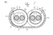
- FIG. 3 is a sectional view taken along line 3-3 in FIG.
- FIG. 4 is a plan view of the composite wire harness of the second embodiment.
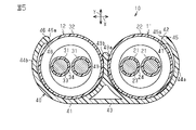
- FIG. 5 is a cross-sectional view taken along the line 5-5 in FIG.
- FIG. 6 is a plan view of the composite wire harness of the third embodiment.
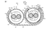
- FIG. 7 is a sectional view taken along line 7-7 in FIG.
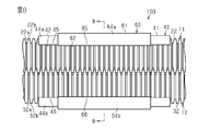
- FIG. 8 is a plan view of the composite wire harness of the fourth embodiment.
- FIG. 9 is a cross-sectional view taken along the line 9-9 in FIG.
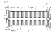
- FIG. 10 is a plan view of the composite wire harness of the fifth embodiment.
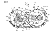
- FIG. 11 is a cross-sectional view taken along the line 11-11 in FIG.
- FIG. 12 is a schematic perspective view of the first route restricting member of the fifth embodiment.
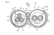
- FIG. 13 is
- the composite wire harness of the present disclosure is [1] A first wire harness having a first electric wire and a first exterior member covering the first electric wire, a second wire harness having a second electric wire and a second exterior member covering the second electric wire, and the above. A first wire harness and a first route restricting member attached to the second wire harness are provided, the first wire harness is arranged side by side with the second wire harness, and the first route restricting member is provided.
- the first main body portion that covers a part of the outer periphery of the first exterior member and the second exterior member, and the first end portion and the second end portion that are both ends in the circumferential direction of the first main body portion.
- the first insertion port has an opening extending in the length direction of the first route restricting member and extends over the entire length of the first route restricting member. The route restricting member collectively holds the first wire harness and the second wire harness.
- the first insertion into the first exterior member and the second exterior member after performing terminal processing such as attaching a connector to the end of each of the first electric wire and the second electric wire in the length direction, the first insertion into the first exterior member and the second exterior member. It is possible to attach the first route restricting member from the mouth. As described above, since the first path restricting member can be retrofitted to the first exterior member and the second exterior member, it is possible to improve the assembling workability of the composite wire harness.
- the first route restricting member collectively holds the first exterior member and the second exterior member, and regulates the routes of the first wire harness and the second wire harness. That is, since the routes of a plurality of wire harnesses can be regulated by one first route restricting member, it is possible to contribute to the reduction of the number of parts of the composite wire harness.
- the first route restricting member is more rigid than the first exterior member and the second exterior member. According to this configuration, the paths of the first wire harness and the second wire harness can be more firmly regulated by the rigid first path restricting member.
- the first path restricting member has a first protruding portion that protrudes from the inner surface of the first end portion and comes into contact with the outer surface of the first exterior member, and the second protruding portion that protrudes from the inner surface of the second end portion. It is provided with a second protrusion that comes into contact with the outer surface of the exterior member.
- the first route restricting member has a partition portion protruding from the first main body portion toward the first insertion port, and the partition portion includes the first exterior member and the second exterior member. It is located between.
- the partition portion divides the portion where the first exterior member is arranged and the portion where the second exterior member is arranged. Therefore, it is possible to improve workability when assembling the first exterior member and the second exterior member to the first route restricting member.
- the tip portion of the partition portion extends in a direction different from that of the first tip portion that covers a part of the outer periphery of the first exterior member and the first tip portion, and is a part of the outer circumference of the second exterior member. It is provided with a second tip portion that covers the surface.
- the tip portion of the partition portion is formed so as to be divided into a first tip portion and a second tip portion.
- the length of the first tip portion and the length of the second tip portion can be set individually. Therefore, the range of the outer circumference of the first exterior member covered by the first tip portion and the range of the outer circumference of the second exterior member covered by the second tip portion can be individually adjusted.
- the partition portion protrudes from the inner surface of the first tip portion toward the first exterior member and from the inner surface of the second tip portion toward the second exterior member. It has a second protrusion.
- the partition portion has a first protrusion that protrudes from the inner surface of the first tip portion toward the first exterior member. As a result, it is possible to prevent the first exterior member from coming off from the first path restricting member by the first protrusion. Further, the partition portion has a second protrusion protruding from the inner surface of the second tip portion toward the second exterior member. As a result, it is possible to prevent the second exterior member from coming off from the first path restricting member by the second protrusion.
- a second path regulating member attached to the outer periphery of the first exterior member is provided, and the second path regulating member includes a second main body portion that covers a part of the outer periphery of the first exterior member, and the second main body portion. It has a second insertion port formed by a third end portion and a fourth end portion which are both ends in the circumferential direction of the main body portion, and the second insertion port is in the length direction of the second path restricting member.
- the second route restricting member is arranged between the outer peripheral surface of the first exterior member and the first route restricting member. ..
- the first exterior member can be more preferably protected from flying objects and the like. As a result, it can contribute to the improvement of the durability of the composite wire harness.
- first route restricting member and the second route restricting member make it possible to more preferably regulate the routes of the first wire harness and the second wire harness. Further, since the first exterior member is double covered by the first path restricting member and the second path regulating member, heat transfer from the outside to the first exterior member can be more preferably suppressed.
- the second insertion port of the second route restricting member is an opening extending in the length direction of the second route restricting member and extends over the entire length of the second route restricting member. This makes it possible to attach the second path restricting member from the second insertion port to the first exterior member after performing terminal processing such as attaching a connector to the end of the first electric wire in the length direction. .. As described above, since the second path restricting member can be retrofitted to the first exterior member, it can contribute to the improvement of the assembly workability of the composite wire harness.
- the second path restricting member is more rigid than the first exterior member. According to this configuration, the path of the first wire harness can be regulated more firmly by the rigid second path restricting member.
- the second route restricting member is longer than the first route restricting member in the length direction of the first wire harness. According to this configuration, for example, when the first wire harness requires a route regulation in a section longer than that of the second wire harness, the first exterior member does not correspond by lengthening the first route restricting member.
- the second route restricting member attached to the above it is possible to regulate only the parts that require route regulation. That is, it is not necessary to extend the first route restricting member to the section where the route regulation is not required in the second wire harness, and as a result, it contributes to the miniaturization of the first route regulating member and eventually to the weight reduction of the composite wire harness. Can contribute.
- the second path restricting member has a third protruding portion that protrudes from the inner surface of at least one of the third end portion and the fourth end portion and comes into contact with the outer surface of the first exterior member. According to this configuration, it is possible to prevent the first exterior member from coming off the second path restricting member through the second insertion slot by the third protrusion. As a result, it is possible to prevent the second path restricting member from being unintentionally disengaged, so that the workability of assembling the composite wire harness can be further improved.
- a third route regulating member attached to the first route regulating member is provided, and the third route regulating member includes a third main body portion that covers the outer periphery of the first route regulating member and the third main body portion. It has a third insertion port formed by a fifth end portion and a sixth end portion which are both ends in the circumferential direction, and the third insertion port is an opening extending in the length direction of the third path restricting member. At the same time, it extends over the entire length of the third route restricting member.
- the third route restricting member is provided on the outside of the first route restricting member, the first exterior member and the second exterior member can be more preferably protected from flying objects and the like. As a result, it can contribute to the improvement of the durability of the composite wire harness.
- first route restricting member and the third route restricting member make it possible to more preferably regulate the routes of the first wire harness and the second wire harness. Further, since the first exterior member and the second exterior member are double covered by the first path regulating member and the third path regulating member, heat is transferred from the outside to the first exterior member and the second exterior member. Can be more preferably suppressed.
- the third insertion port of the third route restricting member is an opening extending in the length direction of the third route restricting member and extends over the entire length of the third route restricting member.
- the third path restricting member can be retrofitted through the third insertion slot, which can contribute to the improvement of the assembly workability of the composite wire harness.
- the third path restricting member is more rigid than the first exterior member and the second exterior member. According to this configuration, the paths of the first wire harness and the second wire harness can be more firmly regulated by the rigid third path restricting member.
- the third route restricting member is shorter than the first route restricting member in the length direction of the first route restricting member. According to this configuration, it is possible to provide the third route restricting member only in the place where the third route restricting member is required in the composite wire harness. Therefore, it is not necessary to extend the third route restricting member to a place where the third route restricting member is not required, and as a result, it contributes to the miniaturization of the third route regulating member and further to the weight reduction of the composite wire harness. ..
- the third path restricting member is made of a metal material. According to this configuration, the third path restricting member made of a metal material can effectively shield the heat transferred from the outside to the first exterior member and the second exterior member.
- the first route restricting member is made of a synthetic resin material. According to this configuration, the first exterior member and the first path restricting member provided between the second exterior member and the third path restricting member are made of a synthetic resin material. Therefore, it is possible to prevent the metal third route restricting member from touching the first exterior member and the second exterior member by the synthetic resin first route restricting member. As a result, it is possible to suppress wear of the first exterior member and the second exterior member due to contact with the metal third path restricting member.
- the third path restricting member is made of a colored synthetic resin material. According to this configuration, it is possible to make the third path restricting member a desired color without applying coating or the like to the surface. For example, when at least one of the first electric wire and the second electric wire is a high-voltage electric wire, the operator can recognize the color of the first path restricting member and that at least one of the first electric wire and the second electric wire is a high-voltage electric wire. Coloring can alert the operator to prevent accidental cutting of composite wire harnesses, including high-voltage power lines.
- the first path restricting member is made of a colored synthetic resin material
- the third path regulating member is made of a synthetic resin material having the same color as the first path regulating member. According to this configuration, it is possible to make the first path regulating member and the third path regulating member a desired color without coating the surface. For example, when at least one of the first electric wire and the second electric wire is a high-voltage electric wire, the operator can recognize the color of the first path restricting member and that at least one of the first electric wire and the second electric wire is a high-voltage electric wire. Coloring can alert the operator to prevent accidental cutting of composite wire harnesses, including high-voltage power lines.
- the second path restricting member is made of a colored synthetic resin material. According to this configuration, it is possible to make the second path restricting member a desired color without applying coating or the like to the surface. For example, when the first electric wire is a high-voltage electric wire, the color of the second path restricting member is changed so that the operator can recognize that the first electric wire is a high-voltage electric wire, so that the first wire harness including the high-voltage electric wire can be used. It is possible to call attention to prevent the operator from accidentally disconnecting.
- the first path restricting member is made of a colored synthetic resin material
- the second path regulating member is made of a synthetic resin material having the same color as the first path regulating member. According to this configuration, it is possible to make the first path regulating member and the second path regulating member a desired color without coating the surface. For example, when the first electric wire is a high-voltage electric wire, the color of the first path regulating member and the second path regulating member is changed to a color that the operator can recognize that the first electric wire is a high-voltage electric wire. It is possible to call attention so that the operator does not accidentally cut the first wire harness including the above.
- the first route restricting member is made of a colored synthetic resin material. According to this configuration, it is possible to make the first path restricting member a desired color without applying coating or the like to the surface. For example, when at least one of the first electric wire and the second electric wire is a high-voltage electric wire, the operator can recognize the color of the first path restricting member and that at least one of the first electric wire and the second electric wire is a high-voltage electric wire. Coloring can alert the operator to prevent accidental cutting of composite wire harnesses, including high-voltage power lines.
- the first route restricting member is made of a metal material. According to this configuration, the first path restricting member made of a metal material can effectively shield the heat transferred from the outside to the first exterior member and the second exterior member.
- the first exterior member has a larger outer shape than the second exterior member.
- the first route restricting member collectively holds the first exterior member and the second exterior member having different outer sizes, and routes the first wire harness and the second wire harness. regulate. That is, even when the outer dimensions of the first exterior member and the second exterior member are different from each other, the routes of a plurality of wire harnesses can be restricted by one first route restricting member. This can contribute to the reduction of the number of parts of the composite wire harness.
- the first wire harness has two first wires
- the second wire harness has three second wires
- the two first wires are DC circuits.
- the three second electric wires are electric wires constituting a three-phase circuit.
- one path is a path between a first wire harness having two first wires constituting a DC circuit and a second wire harness having three second wires constituting a three-phase circuit. It can be regulated by one route regulation member. Thereby, for example, the routes of the first wire harness and the second wire harness used in the four-wheel drive vehicle can be regulated by one first route restricting member. Therefore, it is possible to contribute to the reduction of the number of parts of the composite wire harness.
- the "cylindrical shape" used in the description of the present specification is not limited to the one in which a peripheral wall is continuously formed over the entire circumference in the circumferential direction, but also the one in which a plurality of parts are combined to form a tubular shape, or a C-shape. It also includes those having a notch in a part in the circumferential direction such as a shape.
- “cylindrical” shapes include circles, ellipses, and polygons with sharp or rounded corners.
- the term “annular” refers to any structure that forms a loop, or a continuous shape with no ends, as well as a generally loop shape with a C-shaped gap. May refer to the structure of. It should be noted that the "annular" shape includes, but is not limited to, a circle, an ellipse, and a polygon having sharp or rounded corners.
- the composite wire harness 10 shown in FIG. 1 connects, for example, devices provided in the vehicle V to each other.
- the composite wire harness 10 is arranged in the vehicle V so that, for example, the intermediate portion of the composite wire harness 10 in the length direction passes outside the vehicle interior such as under the floor of the vehicle V.
- the composite wire harness 10 includes a first wire harness 11 and a second wire harness 12 arranged side by side with each other.
- the first wire harness 11 and the second wire harness 12 are arranged so as to be parallel to each other, for example.
- the composite wire harness 10 includes the first path restricting member 40 shown in FIG. 2.
- the first route restricting member 40 collectively holds the first wire harness 11 and the second wire harness 12. In FIG. 1, the illustration of the first route restricting member 40 is omitted.
- the first wire harness 11 electrically connects the first device M1 and the second device M2 provided on the vehicle V to each other.
- the first device M1 is a high-voltage battery arranged at a position near the rear of the vehicle V
- the second device M2 is placed at a position near the front of the vehicle V.
- It is an inverter.
- the first device M1 as a high-voltage battery is, for example, a battery capable of supplying a voltage of 100 volts or more.
- the second device M2 as an inverter is connected to a motor (not shown) for driving wheels, which is a power source for traveling the vehicle.
- the inverter generates AC power from the DC power of the high-voltage battery and supplies the AC power to the motor.
- the first wire harness 11 is a high-voltage wire harness that enables high-voltage exchange between the high-voltage battery and the inverter.
- the second wire harness 12 electrically connects the third device M3 and the fourth device M4 provided in the vehicle V to each other.
- the third device M3 is a low-voltage battery arranged at a position near the rear of the vehicle V
- the fourth device M4 is installed at a place near the front of the vehicle V. It is a relay box.
- the fourth device M4 as a relay box distributes the voltage of the low voltage battery to various devices mounted on the vehicle V.
- the second wire harness 12 is a low-voltage wire harness that can handle the supply current of the low-voltage battery.
- Each of the first wire harness 11 and the second wire harness 12 is formed so as to be bent in a two-dimensional shape or a three-dimensional shape according to the wiring path.
- the first wire harness 11 has a first electric wire 21 and a first exterior member 22.
- a plurality of first electric wires 21 are provided, for example.
- the first exterior member 22 has, for example, a cylindrical shape.
- the first exterior member 22 collectively surrounds, for example, a plurality of first electric wires 21.
- One end of the first electric wire 21 is connected to the first device M1, and the other end of the first electric wire 21 is connected to the second device M2.
- the first electric wire 21 is a high-voltage electric wire that can handle high voltage and large current.
- the first electric wire 21 has a first core wire 23 and a first insulating coating 24 that covers the outer periphery of the first core wire 23.
- the first core wire 23 is made of, for example, a flexible conductor that can be easily bent.
- An example of the flexible conductor is a stranded wire obtained by twisting a plurality of metal strands.
- a metal material such as copper-based or aluminum-based can be used.
- the first insulating coating 24 covers, for example, the outer peripheral surface of the first core wire 23 over the entire circumference.
- the first insulating coating 24 is made of an insulating material such as a synthetic resin.
- the first insulating coating 24 can be formed, for example, by extrusion molding on the first core wire 23.
- the first exterior member 22 has a long tubular shape as a whole.
- a first electric wire 21 is inserted in the internal space of the first exterior member 22.
- the first exterior member 22 protects the first electric wire 21 from, for example, flying objects and water droplets.
- the first exterior member 22 is made of, for example, a corrugated tube made of synthetic resin.
- the first exterior member 22 as a corrugated tube has a bellows shape in which the diameter repeats in the length direction. That is, the first exterior member 22 has recesses 22a and protrusions 22b that are alternately connected in the length direction of the first exterior member 22.
- Each of the concave portion 22a and the convex portion 22b forms, for example, an annular shape that makes one round along the circumferential direction of the first exterior member 22.
- the first exterior member 22 made of a corrugated tube is flexible and can be easily bent.
- a synthetic resin such as polyolefin, polyamide, polyester, or ABS resin can be used.
- the second wire harness 12 has a second electric wire 31 and a second exterior member 32.
- a plurality of second electric wires 31 are provided, for example.
- the second exterior member 32 has, for example, a cylindrical shape.
- the second exterior member 32 collectively surrounds, for example, a plurality of second electric wires 31.
- One end of the second electric wire 31 is connected to the third device M3, and the other end of the second electric wire 31 is connected to the fourth device M4.
- the second electric wire 31 is a low voltage electric wire.
- the second electric wire 31 has a second core wire 33 and a second insulating coating 34 that covers the outer periphery of the second core wire 33.
- the second core wire 33 is made of, for example, a flexible conductor that can be easily bent.
- An example of the flexible conductor is a stranded wire obtained by twisting a plurality of metal strands.
- a metal material such as copper-based or aluminum-based can be used.
- the second insulating coating 34 covers, for example, the outer peripheral surface of the second core wire 33 over the entire circumference.
- the second insulating coating 34 is made of an insulating material such as a synthetic resin.
- the second insulating coating 34 can be formed, for example, by extrusion molding on the second core wire 33.
- the second exterior member 32 has a long tubular shape as a whole.
- a second electric wire 31 is inserted in the internal space of the second exterior member 32.
- the second exterior member 32 protects the second electric wire 31 from, for example, flying objects and water droplets.
- the second exterior member 32 is composed of, for example, a corrugated tube made of synthetic resin.
- the second exterior member 32 as a corrugated tube has a bellows shape in which the diameter repeats in the length direction. That is, the second exterior member 32 has concave portions 32a and convex portions 32b that are alternately connected in the length direction of the second exterior member 32.
- Each of the concave portion 32a and the convex portion 32b forms, for example, an annular shape that makes one round along the circumferential direction of the second exterior member 32.
- the second exterior member 32 made of a corrugated tube is flexible and can be easily bent.
- a synthetic resin such as polyolefin, polyamide, polyester, or ABS resin can be used.
- the first exterior member 22 and the second exterior member 32 are arranged along the X axis.
- the X-axis is perpendicular to the length direction of the first exterior member 22 and the second exterior member 32.
- the direction along the X axis may be referred to as the side-by-side direction X of the first exterior member 22 and the second exterior member 32.
- the first route restricting member 40 collectively holds the first exterior member 22 and the second exterior member 32. Further, the first route restricting member 40 is more rigid than the first exterior member 22 and the second exterior member 32. That is, the first path restricting member 40 has a hardness that is less likely to bend in a direction orthogonal to the length direction of the first wire harness 11 and the second wire harness 12 than the first exterior member 22 and the second exterior member 32. Have. As a result, the first route restricting member 40 regulates the route of the first wire harness 11 and the route of the second wire harness 12.
- the first path restricting member 40 assists the first wire harness 11 and the second wire harness 12 so that the first wire harness 11 and the second wire harness 12 do not bend due to their own weight or the like and do not deviate from the predetermined path. .. Therefore, the first exterior member 22 and the second exterior member 32 are more difficult to bend than the state in which the first route restricting member 40 is not attached.
- the first route restricting member 40 is partially provided in the length direction of the first wire harness 11 and the second wire harness 12.
- the first path restricting member 40 is attached to, for example, a portion extending linearly in the path of the first wire harness 11 and the second wire harness 12.
- the first route restricting member 40 is provided singularly or plurally depending on the routes of the first wire harness 11 and the second wire harness 12.
- the first route restricting member 40 includes a first main body portion 41 that covers a part of the outer periphery of the first exterior member 22 and the second exterior member 32, and a first insertion port 42.
- the first main body portion 41 covers a part of the outer periphery of the first exterior member 22 and the second exterior member 32 arranged in the parallel arrangement direction X.
- the first main body portion 41 extends, for example, linearly along the length direction of the first exterior member 22 and the second exterior member 32.
- the cross-sectional shape of the first main body 41 is, for example, substantially C-shaped.
- the cross-sectional shape of the first route restricting member 40 is, for example, uniform over the entire length of the first route restricting member 40. Further, the thickness of the first main body portion 41 in the radial direction is uniform in the circumferential direction, for example.
- the first main body portion 41 is a covering portion 43, a pair of arm portions 44a and 44b, a first end portion 45 which is a tip portion of the arm portion 44a, and a tip portion of the arm portion 44b. It has a second end 46.
- the covering portion 43 covers, for example, the side of the first exterior member 22 and the second exterior member 32 in the Y-axis direction perpendicular to the parallel direction X.
- the pair of arm portions 44a and 44b extend from both ends of the covering portion 43 in the parallel direction X, respectively.
- the pair of arm portions 44a and 44b collectively sandwich the first exterior member 22 and the second exterior member 32 from both sides in the parallel direction X.
- the arm portions 44a and 44b extend to the side opposite to the side covered by the covering portion 43 in the Y-axis direction. That is, the first end portion 45 of the arm portion 44a and the second end portion 46 of the arm portion 44b are located on opposite sides to the side covered by the covering portion 43 in the Y-axis direction.
- the arm portion 44a covers the side of the first exterior member 22 in the parallel arrangement direction X.
- the arm portion 44b covers the side of the second exterior member 32 in the parallel arrangement direction X.
- the first end portion 45 and the second end portion 46 are both ends in the circumferential direction of the first main body portion 41.
- the first end portion 45 and the second end portion 46 face each other in a state of being separated from each other in the circumferential direction of the first main body portion 41.
- the first insertion slot 42 is formed by the first end portion 45 and the second end portion 46. That is, the gap between the first end portion 45 and the second end portion 46 is configured as the first insertion port 42.
- the first exterior member 22 and the second exterior member 32 are in contact with each other in a state of being sandwiched between the pair of arm portions 44a and 44b.
- the unevenness of the outer peripheral surface of the first exterior member 22 meshes with the unevenness of the outer peripheral surface of the second exterior member 32 at least in the portion held by the first path restricting member 40. That is, the convex portion 22b of the first exterior member 22 is fitted into the concave portion 32a of the second exterior member 32, and the convex portion 32b of the second exterior member 32 is fitted into the concave portion 22a of the first exterior member 22.
- the composite wire harness 10 can be miniaturized in the parallel arrangement direction X by the amount of engagement between the first exterior member 22 and the second exterior member 32. Further, the relative movement of the first exterior member 22 and the second exterior member 32 in the length direction can be regulated by the engagement of the first exterior member 22 and the second exterior member 32.
- the first insertion port 42 is an opening along the length direction of the first path restricting member 40. Further, the first insertion port 42 opens along the Y axis. That is, the first insertion port 42 opens in a direction perpendicular to the parallel direction X. Further, the first insertion port 42 extends over the entire length of the first path restricting member 40.
- the opening width of the first insertion port 42 that is, the shortest distance between the first end portion 45 and the second end portion 46, is the sum of the outer diameter of the first exterior member 22 and the outer diameter of the second exterior member 32. It is smaller than the length obtained by subtracting the meshing portion of the unevenness of the first exterior member 22 and the second exterior member 32 from the length. The first exterior member 22 and the second exterior member 32 are inserted into the first insertion port 42 along the Y-axis direction.
- the first path restricting member 40 has a first protruding portion 47 protruding from the inner surface of the first end portion 45, and a second protruding portion 48 protruding from the inner surface of the second end portion 46.
- the cross-sectional shape of the first protruding portion 47 and the second protruding portion 48 is, for example, a semicircular shape.
- the first protrusion 47 and the second protrusion 48 extend, for example, along the length direction of the first path restricting member 40. Further, the first protruding portion 47 and the second protruding portion 48 extend over the entire length of the first path restricting member 40, for example.
- the first protruding portion 47 protrudes toward the first exterior member 22.
- the first protruding portion 47 is in contact with the outer surface of the first exterior member 22.
- the second protruding portion 48 protrudes toward the second exterior member 32.
- the second protruding portion 48 is in contact with the outer surface of the second exterior member 32.
- the first protruding portion 47 and the second protruding portion 48 press, for example, the first exterior member 22 and the second exterior member 32, respectively.
- the first exterior member 22 and the second exterior member 32 are elastically sandwiched by the first projecting portion 47, the second projecting portion 48, and the first main body portion 41. As a result, the connection of the first route restricting member 40 to the first exterior member 22 and the second exterior member 32 is strengthened. Therefore, the movement of the first route restricting member 40 in the length direction of the first exterior member 22 and the second exterior member 32 is suppressed.
- the opening width of the first insertion port 42 is the original width, that is, the first exterior member 22 and the first. 2 It does not always return to the width when the exterior member 32 is not inserted. Specifically, the elastic deformation that the arm portions 44a and 44b try to return to the original shape is hindered by the first exterior member 22 and the second exterior member 32, so that the opening width of the first insertion port 42 is the original width. It can be slightly wider than.
- the opening width of the first insertion port 42 may return to the original width. That is, the opening width of the first insertion port 42 in a state where the first exterior member 22 and the second exterior member 32 are inserted inside the first path restricting member 40 is the first exterior member 22 and the second exterior member 32.
- the size is based on the rigidity and flexibility of the first path restricting member 40.
- each of the circumferential tip 45a of the first end portion 45 and the circumferential tip 46a of the second end portion 46 is the first path restricting member 40. It is curved when viewed from the length direction. In other words, the cross-sectional shape of the tip 45a of the first end 45 and the tip 46a of the second end 46 is a curved shape.
- the first insertion port 42 is formed by the tip 45a of the first end 45 and the tip 46a of the second end 46.
- the first protruding portion 47 protrudes from the inner surface of the tip 45a of the first end portion 45.
- the second protruding portion 48 protrudes from the inner surface of the tip 46a of the second end portion 46.
- the material of the first path restricting member 40 for example, a synthetic resin such as polypropylene, polyamide, or polyacetal can be used.
- the first path restricting member 40 can be molded by a well-known method such as extrusion molding or injection molding.
- the first path restricting member 40 is harder than the first exterior member 22 and the second exterior member 32, but the constituent material of the first route regulating member 40 is the configuration of the first exterior member 22. It does not have to be a material that is harder than the material and the constituent material of the second exterior member 32. That is, the constituent material of the first route restricting member 40 may be a hard material or a soft material with respect to the constituent material of the first exterior member 22 and the constituent material of the second exterior member 32. Further, the constituent material of the first route restricting member 40 may be the same material as the constituent material of the first exterior member 22 and the constituent material of the second exterior member 32.
- the first route restricting member 40 of the present embodiment is made of, for example, a colored synthetic resin material.
- the color of the synthetic resin material constituting the first path restricting member 40 is set to a color that the operator can recognize that the electric wire included in the composite wire harness 10 is a high-voltage electric wire.
- the composite wire harness 10 is fixed to the vehicle body by a fixing member (not shown). In the path of the composite wire harness 10, a plurality of fixing points to the vehicle body by the fixing member are provided.
- the fixed point is set in a section provided with the first route restricting member 40 or a section not provided with the first route restricting member 40.
- the first wire harness 11 and the second wire harness 12 are caused by their own weight or the like due to the rigidity of the first path restricting member 40. Flexion is suppressed. That is, the first route restricting member 40 regulates the routes of both the first wire harness 11 and the second wire harness 12.
- the first exterior member 22 is a hard pipe member such as a metal pipe, and the pipe member realizes both protection of the first electric wire 21 and route regulation.
- the pipe member becomes long, and it is necessary to bend the pipe member by a bender or the like at a bending point in the path of the first electric wire 21.
- the bending process is a complicated task.
- the composite wire harness 10 of the present embodiment since the first path restricting member 40 is attached to the straight line portion of the path of the composite wire harness 10, bending processing by a conventional bender machine or the like is unnecessary.
- the first insertion port 42 of the first route restricting member 40 is an opening extending in the length direction of the first route restricting member 40 and extends over the entire length of the first route restricting member 40. According to this configuration, after performing terminal processing such as attaching a connector to each end of the first electric wire 21 and the second electric wire 31 in the length direction, the first exterior member 22 and the second exterior member 32 are subjected to terminal processing. It is possible to attach the first route restricting member 40 from the first insertion port 42. As described above, since the first path restricting member 40 can be retrofitted to the first exterior member 22 and the second exterior member 32, it is possible to improve the assembling workability of the composite wire harness 10.
- first route restricting member 40 collectively holds the first exterior member 22 and the second exterior member 32, and regulates the routes of the first wire harness 11 and the second wire harness 12. That is, since the routes of the plurality of wire harnesses can be regulated by one first route restricting member 40, it is possible to contribute to the reduction of the number of parts of the composite wire harness 10.
- the first route restricting member 40 is harder than the first exterior member 22 and the second exterior member 32. That is, the first path restricting member 40 has a hardness that is less likely to bend than the first exterior member 22 and the second exterior member 32. According to this configuration, the path of the first wire harness 11 and the second wire harness 12 can be more firmly regulated by the rigid first path restricting member 40.
- the first path restricting member 40 protrudes from the inner surface of the first end portion 45 and comes into contact with the outer surface of the first exterior member 22, and the first projecting portion 47 protrudes from the inner surface of the second end portion 46.
- a second protruding portion 48 that comes into contact with the outer surface of the exterior member 32 is provided. According to this configuration, it is possible to prevent the first exterior member 22 and the second exterior member 32 from coming off the first path restricting member 40 through the first insertion port 42 by the first protrusion 47 and the second protrusion 48. As a result, the first path restricting member 40 is prevented from being unintentionally disengaged, so that the assembly workability of the composite wire harness 10 can be further improved.
- the first route restricting member 40 is made of a colored synthetic resin material. According to this configuration, it is possible to make the first path restricting member 40 a desired color without applying coating or the like to the surface. As a result, the color of the first path restricting member 40 is changed so that the operator can recognize that the composite wire harness 10 includes the first electric wire 21 as a high-voltage electric wire, so that the operator can make the first electric wire 21. You can call attention not to accidentally disconnect.
- Each of the tip 45a of the first end portion 45 and the tip 46a of the second end portion 46 is curved when viewed from the length direction of the first path restricting member 40. Therefore, the first exterior member 22 and the second exterior member 32 can be smoothly inserted into the inside of the first path restricting member 40 from the first insertion port 42 formed at the tips 45a and 46a, respectively. Become. Further, when the first exterior member 22 and the second exterior member 32 are inserted into the inside of the first route restricting member 40 from the first insertion port 42, the first exterior member 22 and the second exterior member 32 are less likely to be damaged.
- the cross-sectional shape of the first route restricting member 40 is the same over the entire length of the first route restricting member 40. According to such a configuration, the first path regulating member 40 can be easily manufactured by using an extrusion molding machine that extrudes the raw material of the first path regulating member 40 in the length direction. Further, a single extruder can be used to manufacture a plurality of types of first path restricting members 40 having different dimensions in the length direction.
- the first protruding portion 47 and the second protruding portion 48 extend over the entire length of the first path restricting member 40. According to such a configuration, the bending rigidity of the first path restricting member 40 can be increased. Further, the first protruding portion 47 and the second protruding portion 48 come into contact with the outer surfaces of the first exterior member 22 and the second exterior member 32, respectively, over the entire length of the first path restricting member 40. Therefore, the detachment of the first route restricting member 40 from the first exterior member 22 and the second exterior member 32 through the first insertion port 42 can be suppressed over the entire length of the first route restricting member 40.
- the first path restricting member 40 has a partition portion 49 protruding from the first main body portion 41 toward the first insertion port 42.
- the partition portion 49 extends, for example, over the entire length of the first route restricting member 40.
- the partition portion 49 is located between the first exterior member 22 and the second exterior member 32. That is, the partition portion 49 partitions between the first exterior member 22 and the second exterior member 32.
- the first exterior member 22 is arranged between the partition portion 49 and the first end portion 45.
- the second exterior member 32 is arranged between the partition portion 49 and the second end portion 46.
- the partition portion 49 has a first protrusion 49a protruding from the tip of the partition 49 toward the first exterior member 22, and a second protrusion 49 protruding from the tip of the partition 49 toward the second exterior member 32. It has 49b and.
- the first protrusion 49a is in contact with the outer peripheral surface of the first exterior member 22.
- the second protrusion 49b is in contact with the outer peripheral surface of the second exterior member 32.
- the shortest distance between the tip of the partition 49 and the first end 45 is smaller than the outer diameter of the first exterior member 22. Further, the shortest distance between the tip end portion of the partition portion 49 and the second end portion 46 is smaller than the outer diameter of the second exterior member 32.
- the partition portion 49 divides the portion where the first exterior member 22 is arranged and the portion where the second exterior member 32 is arranged. Therefore, workability when assembling the first exterior member 22 and the second exterior member 32 to the first route restricting member 40 can be improved.
- the partition portion 49 has a first protrusion 49a protruding from the tip end portion of the partition portion 49 toward the first exterior member 22. As a result, it is possible to prevent the first exterior member 22 from coming off from the first path restricting member 40 by the first protrusion 49a. Further, the partition portion 49 has a second protrusion 49b that protrudes from the tip end portion of the partition portion 49 toward the second exterior member 32. As a result, the second exterior member 32 can be prevented from coming off from the first path restricting member 40 by the second protrusion 49b.
- the composite wire harness 10A of the present embodiment includes a second path restricting member 50 attached to the outer periphery of the first exterior member 22. Further, the composite wire harness 10A includes a first path restricting member 40 that collectively holds the first wire harness 11 and the second wire harness 12. The first route restricting member 40 is arranged outside the second route restricting member 50. That is, the second route restricting member 50 is arranged between the outer peripheral surface of the first exterior member 22 and the first route restricting member 40.
- the second path restricting member 50 covers a part of the outer circumference of the first exterior member 22 in the circumferential direction. Further, the second path restricting member 50 is harder than the first exterior member 22. That is, the second path restricting member 50 has a hardness that is less likely to bend in a direction orthogonal to the length direction of the first wire harness 11 than the first exterior member 22. As a result, the second path restricting member 50 assists the first exterior member 22 so that the first exterior member 22 bends due to its own weight or the like and does not deviate from the predetermined path. That is, the first exterior member 22 is more difficult to bend than the state in which the second path restricting member 50 is not attached.
- the second route restricting member 50 is partially provided in the length direction of the first exterior member 22.
- the second path restricting member 50 is attached to, for example, a portion extending linearly in the path of the first wire harness 11.
- the second path restricting member 50 may be provided singularly or plurally depending on the path of the first wire harness 11.
- the second path restricting member 50 has a second main body portion 51 that covers a part of the outer periphery of the first exterior member 22 in the circumferential direction, and a second insertion port 52.
- the second main body 51 covers a part of the outer peripheral surface of the first exterior member 22 in the circumferential direction.
- the second main body 51 covers a range larger than half of the outer circumference of the first exterior member 22.
- the second main body portion 51 extends along the length direction of the first exterior member 22.
- the cross-sectional shape of the second main body portion 51 is, for example, an arc shape.
- the thickness of the second main body 51 in the radial direction is, for example, uniform in the circumferential direction.
- the cross-sectional shape of the second route restricting member 50 is, for example, uniform over the entire length of the second route restricting member 50. Further, the central axis C in the cross section of the second main body portion 51 forms, for example, a straight line. That is, the second main body 51 has a shape extending linearly in one direction.
- the second main body 51 has a third end 53 and a fourth end 54, which are both ends in the circumferential direction of the second path restricting member 50.
- the third end portion 53 and the fourth end portion 54 face each other in a state of being separated from each other in the circumferential direction of the second path restricting member 50.
- the second insertion port 52 is formed by the third end portion 53 and the fourth end portion 54 of the second main body portion 51. That is, the gap between the third end 53 and the fourth end 54 is configured as the second insertion slot 52.
- the second insertion port 52 is an opening along the length direction of the second path restricting member 50. Further, the second insertion port 52 extends over the entire length of the second path restricting member 50.
- the opening width of the second insertion slot 52 that is, the shortest distance between the third end portion 53 and the fourth end portion 54 is smaller than the outer diameter of the first exterior member 22.
- the first exterior member 22 is inserted into the second insertion port 52 along a direction orthogonal to the length direction of the second path restricting member 50.
- the tangent line of the third end portion 53 passing through the central axis C of the second main body portion 51 is tangent line T1
- the tangent line of the fourth end portion 54 passing through the central axis line C is tangent line.
- T2 the tangent line of the fourth end portion 54 passing through the central axis line C.
- the second path restricting member 50 has a third protruding portion 55 protruding from the inner surface of each of the third end portion 53 and the fourth end portion 54.
- the cross-sectional shape of each third protrusion 55 is, for example, a semicircular shape.
- Each third protrusion 55 extends, for example, along the length direction of the second path restricting member 50. Further, each third protrusion 55 extends over the entire length of the second path restricting member 50, for example.
- Each third protruding portion 55 protrudes toward the first exterior member 22.
- Each third protrusion 55 is in contact with the outer surface of the first exterior member 22. Then, each third protruding portion 55 presses, for example, the first exterior member 22.
- the first exterior member 22 is elastically sandwiched by each of the third protruding portions 55 and the second main body portion 51. As a result, the connection of the second path restricting member 50 to the first exterior member 22 is strengthened. Therefore, the second path restricting member 50 attached to the outer periphery of the first exterior member 22 is suppressed from moving in the length direction of the first exterior member 22.
- the opening width of the second insertion port 52 returns to the original width, that is, the width when the first exterior member 22 is not inserted.
- the elastic deformation of the second path restricting member 50 to return to the original shape is hindered by the first exterior member 22, so that the opening width of the second insertion port 52 is slightly larger than the original width. It may be.
- the first exterior member 22 is bent by the pressing of the second path restricting member 50, so that the second insertion member 22 is inserted.
- the opening width of the mouth 52 may return to the original width. That is, the opening width in a state where the first exterior member 22 is inserted inside the second path restricting member 50 is based on the rigidity and flexibility of the first exterior member 22 and the second path restricting member 50. It becomes the size.
- each of the circumferential tip 53a of the third end 53 and the circumferential tip 54a of the fourth end 54 is curved when viewed from the length direction of the second path restricting member 50. are doing.
- the cross-sectional shape of the tip 53a of the third end 53 and the tip 54a of the fourth end 54 is a curved shape.
- the second insertion port 52 is formed by the tip 53a of the third end 53 and the tip 54a of the fourth end 54.
- the third protruding portion 55 protrudes from the inner surface of each of the tip 53a of the third end 53 and the tip 54a of the fourth end 54.
- the material of the second path restricting member 50 for example, a synthetic resin such as polypropylene, polyamide, or polyacetal can be used.
- the second path restricting member 50 can be molded by a well-known method such as extrusion molding or injection molding. As described above, the second path restricting member 50 is harder than the first exterior member 22, but the constituent material of the second path regulating member 50 is harder as a material than the constituent material of the first exterior member 22. It does not have to be a material. That is, the constituent material of the second path restricting member 50 may be a hard material or a soft material with respect to the constituent material of the first exterior member 22. Further, the constituent material of the second route restricting member 50 may be the same material as the constituent material of the first exterior member 22.
- the second route restricting member 50 of the present embodiment is made of, for example, a colored synthetic resin material.
- the color of the synthetic resin material constituting the second path restricting member 50 is set to a color that allows the operator to recognize that the first electric wire 21 included in the first wire harness 11 is a high-voltage electric wire. .. Further, in the present embodiment, the second route restricting member 50 has the same color as the first route restricting member 40.
- the second route restricting member 50 is arranged inside the first main body 41 of the first route restricting member 40. Further, the second route restricting member 50 is longer than, for example, the first route restricting member 40 in the length direction of the first wire harness 11.
- the arm portion 44a of the first main body portion 41 is in contact with the second main body portion 51 of the second path restricting member 50.
- the arm portion 44a presses, for example, the second main body portion 51 in the parallel direction X.
- the first insertion port 42 of the first route restricting member 40 and the second insertion port 52 of the second route restricting member 50 are opened in the same direction along the Y axis, for example.
- the first end portion 45 of the first main body portion 41 extends more than, for example, the third end portion 53 of the second main body portion 51 in the circumferential direction of the first exterior member 22. As a result, the first end portion 45 faces the outer peripheral surface of the first exterior member 22.
- the first protruding portion 47 of the first end portion 45 is not in contact with the outer peripheral surface of the first exterior member 22, but the present invention is not limited to this. 1
- the protruding portion 47 may be configured to come into contact with the outer peripheral surface of the first exterior member 22.
- the effect of the third embodiment will be described. (9)
- the first route restricting member 40 and the second route restricting member 50 make it possible to more preferably regulate the routes of the first wire harness 11 and the second wire harness 12.
- the first exterior member 22 can be more preferably protected from flying objects and the like. As a result, it can contribute to the improvement of the durability of the composite wire harness 10A.
- first exterior member 22 is double covered by the first path restricting member 40 and the second path restricting member 50, heat transfer from the outside to the first exterior member 22 is more preferably suppressed. Can be done.
- the second insertion port 52 of the second route restricting member 50 is an opening extending in the length direction of the second route restricting member 50 and extends over the entire length of the second route restricting member 50.
- the second path restricting member 50 is attached to the first exterior member 22 from the second insertion port 52. Is possible.
- the second path restricting member 50 can be retrofitted to the first exterior member 22, it can contribute to the improvement of the assembly workability of the composite wire harness 10A.
- first route restricting member 40 collectively holds the first exterior member 22 and the second exterior member 32. Therefore, the first exterior member 22 and the second exterior member 32 can be connected to each other by the first route restricting member 40.
- the second route restricting member 50 is harder than the first exterior member 22. That is, the second path restricting member 50 has a hardness that is less likely to bend than the first exterior member 22. According to this configuration, the path of the first wire harness 11 can be more firmly regulated by the rigid second path restricting member 50.
- the second route restricting member 50 is longer than the first route restricting member 40 in the length direction of the first wire harness 11. According to this configuration, for example, when the first wire harness 11 requires a route regulation in a section longer than that of the second wire harness 12, the first route restricting member 40 is not lengthened to cope with the route regulation. (1) By lengthening the second route restricting member 50 attached to the exterior member 22, it is possible to regulate only the portion requiring the route regulation. That is, it is not necessary to extend the first route restricting member 40 to the section where the route regulation is not required in the second wire harness 12, and as a result, it contributes to the miniaturization of the first route restricting member 40, and eventually the composite wire harness 10A. Can contribute to weight reduction.
- the second path restricting member 50 has a third protruding portion 55 that protrudes from the inner surface of each of the third end portion 53 and the fourth end portion 54 and comes into contact with the outer surface of the first exterior member 22. According to this configuration, the third protrusion 55 can prevent the first exterior member 22 from coming off the second path restricting member 50 through the second insertion port 52. As a result, the second path restricting member 50 is prevented from being unintentionally disengaged, so that the assembly workability of the composite wire harness 10A can be further improved.
- the second path restricting member 50 is made of a colored synthetic resin material. According to this configuration, it is possible to make the second path restricting member 50 a desired color without applying coating or the like to the surface. As a result, the color of the second path restricting member 50 is changed so that the operator can recognize that the first wire harness 11 includes the first electric wire 21 as a high-voltage electric wire, so that the first wire harness 11 can be operated. It is possible to call attention so that a person does not accidentally disconnect.
- the second route regulating member 50 has the same color as the first route regulating member 40. This makes it possible for the operator to more preferably recognize that the composite wire harness 10A includes a high-voltage power line.
- Each of the tip 53a of the third end 53 and the tip 54a of the fourth end 54 is curved when viewed from the length direction of the second path restricting member 50. Therefore, the first exterior member 22 can be smoothly inserted into the inside of the second path restricting member 50 from the second insertion port 52 formed at each of the tips 53a and 54a. Further, when the first exterior member 22 is inserted into the inside of the second route restricting member 50 from the second insertion port 52, the first exterior member 22 is less likely to be damaged.
- the cross-sectional shape of the second route restricting member 50 is the same over the entire length of the second route restricting member 50. According to such a configuration, the second path regulating member 50 can be easily manufactured by using an extrusion molding machine that extrudes the raw material of the second path regulating member 50 in the length direction. Further, a single extruder can be used to manufacture a plurality of types of second path restricting members 50 having different dimensions in the length direction.
- the third protrusion 55 extends over the entire length of the second path restricting member 50. According to such a configuration, the bending rigidity of the second path restricting member 50 can be increased. Further, the third protrusion 55 contacts the outer surface of the first exterior member 22 over the entire length of the second path restricting member 50. Therefore, the detachment of the second route restricting member 50 from the first exterior member 22 through the second insertion port 52 can be suppressed over the entire length of the second route restricting member 50.
- the composite wire harness 10B of the present embodiment includes a third route restricting member 60 attached to the outer peripheral side of the first route restricting member 40.
- the third route restricting member 60 regulates the routes of the first wire harness 11 and the second wire harness 12.
- the third route restricting member 60 includes a third main body portion 61 that covers a part of the outer periphery of the first route restricting member 40, and a third insertion port 62.
- the third route restricting member 60 is made of, for example, a metal material.
- the third path restricting member 60 can be formed by, for example, a method such as press working or casting of a metal plate.
- the third main body portion 61 has a shape that is one size larger than the first main body portion 41 of the first route restricting member 40.
- the third main body portion 61 extends, for example, linearly along the length direction of the first exterior member 22 and the second exterior member 32. That is, the third main body portion 61 extends in the length direction of the first main body portion 41.
- the cross-sectional shape of the third main body portion 61 is, for example, substantially C-shaped.
- the cross-sectional shape of the third route restricting member 60 is, for example, uniform over the entire length of the third route restricting member 60.
- the thickness of the third main body portion 61 in the radial direction is uniform in the circumferential direction, for example.
- the third main body 61 is shorter than the first main body 41 in the length direction of the first path restricting member 40, for example.
- the third main body portion 61 includes a covering portion 63, a pair of arm portions 64a and 64b, a fifth end portion 65 which is a tip portion of the arm portion 64a, and a tip portion of the arm portion 64b. It has a sixth end 66.
- the covering portion 63 covers the outside of the covering portion 43 in the Y-axis direction perpendicular to the parallel direction X, for example.
- the covering portion 63 is in contact with, for example, the covering portion 43.
- the pair of arm portions 64a and 64b extend from both ends of the covering portion 63 in the parallel direction X, respectively.
- the pair of arm portions 64a and 64b sandwich the first path restricting member 40 from both sides in the parallel direction X.
- the arm portion 64a is in contact with the arm portion 44a of the first path restricting member 40.
- the arm portion 64b is in contact with the arm portion 44b of the first route restricting member 40.
- the fifth end 65 which is the tip of the arm 64a, extends in the circumferential direction of the first exterior member 22 from, for example, the first end 45 of the first main body 41. As a result, the fifth end portion 65 faces the outer peripheral surface of the first exterior member 22.
- the sixth end portion 66 which is the tip end portion of the arm portion 64b, extends in the circumferential direction of the second exterior member 32, for example, from the second end portion 46 of the first main body portion 41. As a result, the sixth end portion 66 faces the outer peripheral surface of the second exterior member 32.
- the fifth end portion 65 and the sixth end portion 66 are both ends in the circumferential direction of the third main body portion 61.
- the fifth end portion 65 and the sixth end portion 66 are located on sides opposite to the side covered by the covering portion 63 in the Y-axis direction.
- the fifth end portion 65 and the sixth end portion 66 face each other in a state of being separated from each other in the circumferential direction of the third main body portion 61.
- the third insertion slot 62 is formed by the fifth end portion 65 and the sixth end portion 66. That is, the gap between the fifth end portion 65 and the sixth end portion 66 is configured as the third insertion port 62.
- the third insertion port 62 is an opening along the length direction of the third path restricting member 60. Further, the third insertion port 62 opens along the Y axis. That is, the third insertion port 62 opens in a direction perpendicular to the parallel direction X. Further, the third insertion port 62 extends over the entire length of the third path restricting member 60.
- the opening width of the third insertion slot 62 that is, the shortest distance between the fifth end portion 65 and the sixth end portion 66 is smaller than the dimension of the first path restricting member 40 in the parallel direction X.
- the first path restricting member 40 is inserted into the third insertion port 62 along the Y-axis direction.
- the third path restricting member 60 has a fourth protruding portion 67 projecting from the inner surface of each of the fifth end portion 65 and the sixth end portion 66.
- the cross-sectional shape of each of the fourth protrusions 67 is, for example, a semicircular shape.
- Each fourth protrusion 67 extends, for example, along the length direction of the third path restricting member 60. Further, each of the fourth protrusions 67 extends over the entire length of the third path restricting member 60, for example.
- the fourth protruding portion 67 provided at the fifth end portion 65 is in contact with, for example, the first end portion 45 of the first main body portion 41. Further, the fourth protruding portion 67 provided at the sixth end portion 66 is in contact with, for example, the second end portion 46 of the first main body portion 41. In the configuration shown in FIG. 9, the fourth protruding portion 67 is not in contact with the outer peripheral surface of the first exterior member 22 and the outer peripheral surface of the second exterior member 32, but the fourth protruding portion 67 is not limited to this. It may be configured to be in contact with the outer peripheral surface of the first exterior member 22 and the outer peripheral surface of the second exterior member 32, respectively.
- each of the circumferential tip 65a of the fifth end portion 65 and the circumferential tip 66a of the sixth end portion 66 of the third path restricting member 60 It is curved when viewed from the length direction.
- the cross-sectional shape of the tip 65a of the fifth end 65 and the tip 66a of the sixth end 66 is a curved shape.
- the third insertion port 62 is formed by the tip 65a of the fifth end 65 and the tip 66a of the sixth end 66.
- the fourth protruding portion 67 protrudes from the inner surfaces of the tip 65a of the fifth end 65 and the tip 66a of the sixth end 66.
- the first route restricting member 40 is provided between the first exterior member 22 and the second exterior member 32 and the third route restricting member 60.
- the first insertion port 42 of the first route restricting member 40 and the third insertion port 62 of the third route restricting member 60 are opened in the same direction along the Y axis, for example.
- the third route restricting member 60 is more rigid than the first exterior member 22 and the second exterior member 32. That is, the third path restricting member 60 has a hardness that is less likely to bend in a direction orthogonal to the length direction of the first wire harness 11 and the second wire harness 12 than the first exterior member 22 and the second exterior member 32. Have. As a result, the third route restricting member 60 regulates the route of the first wire harness 11 and the route of the second wire harness 12. That is, the first exterior member 22 and the second exterior member 32 are more difficult to bend than the state in which the third route restricting member 60 is not attached.
- the first route restricting member 40 and the third route restricting member 60 make it possible to more preferably regulate the routes of the first wire harness 11 and the second wire harness 12.
- the third route restricting member 60 is provided on the outside of the first route restricting member 40, the first exterior member 22 and the second exterior member 32 can be more preferably protected from flying objects and the like. As a result, it can contribute to the improvement of the durability of the composite wire harness 10B.
- first exterior member 22 and the second exterior member 32 are double covered by the first route restricting member 40 and the third route restricting member 60, the first exterior member 22 and the second exterior member are covered from the outside. It is possible to more preferably suppress the transfer of heat to 32.
- the third insertion port 62 of the third route restricting member 60 is an opening extending in the length direction of the third route restricting member 60 and extends over the entire length of the third route restricting member 60.
- the third path restricting member 60 can be retrofitted through the third insertion port 62, which can contribute to the improvement of the assembly workability of the composite wire harness 10B.
- the third route restricting member 60 is harder than the first exterior member 22 and the second exterior member 32. That is, the third path restricting member 60 has a hardness that is less likely to bend than the first exterior member 22 and the second exterior member 32. According to this configuration, the paths of the first wire harness 11 and the second wire harness 12 can be more firmly regulated by the rigid third path restricting member 60.
- the third route regulating member 60 is shorter than the first route regulating member 40 in the length direction of the first route regulating member 40. According to this configuration, it is possible to provide the third route restricting member 60 only at the portion where the third route restricting member 60 is required in the composite wire harness 10B. Therefore, it is not necessary to extend the third route restricting member 60 to a place where the third route restricting member 60 is not required, and as a result, it contributes to the miniaturization of the third route regulating member 60, and by extension, the weight of the composite wire harness 10B. Can contribute to the conversion.
- the third route restricting member 60 is made of a metal material. According to this configuration, the third path restricting member 60 made of a metal material can effectively shield the heat transferred from the outside to the first exterior member 22 and the second exterior member 32.
- the first route restricting member 40 provided between the first exterior member 22 and the second exterior member 32 and the third route restricting member 60 is made of a synthetic resin material. Therefore, it is possible to prevent the metal third path regulating member 60 from touching the first exterior member 22 and the second exterior member 32 by the synthetic resin first path regulating member 40. As a result, it is possible to suppress wear of the first exterior member 22 and the second exterior member 32 due to contact with the metal third path restricting member 60.
- the composite wire harness 10C of the present embodiment is attached to the first wire harness 11A, the second wire harness 12A, the first wire harness 11A, and the second wire harness 12A. It is provided with a route restricting member 40.
- the first wire harness 11A and the second wire harness 12A are arranged side by side with each other.
- the first wire harness 11A and the second wire harness 12A have different outer shapes from each other.
- the first wire harness 11A has a larger outer shape than, for example, the second wire harness 12A.
- the first wire harness 11A has two first electric wires 21 and a tubular first exterior member 22 that collectively surrounds the two first electric wires 21.
- the second wire harness 12A has three second electric wires 31 and a tubular second exterior member 32 that collectively surrounds the three second electric wires 31.
- the two first electric wires 21 are electric wires constituting a DC circuit.
- the two first electric wires 21 are, for example, a high-voltage electric wire on the plus side and a high-voltage electric wire on the minus side.
- the three second electric wires 31 are electric wires constituting a three-phase circuit.
- the three second electric wires 31 are, for example, a three-phase cable.
- Each first electric wire 21 has a larger outer shape than, for example, each second electric wire 31.
- both the first electric wire 21 and the second electric wire 31 of the present embodiment are formed in a columnar shape.
- the outer diameter of each first electric wire 21 is larger than the outer diameter of each second electric wire 31.
- the first exterior member 22 has a larger outer shape than, for example, the second exterior member 32.
- both the first exterior member 22 and the second exterior member 32 of the present embodiment are formed in a cylindrical shape.
- the outer diameter of the first exterior member 22 is larger than the outer diameter of the second exterior member 32.
- the first route restricting member 40 has a first main body portion 41 and a first insertion port 42.
- the first main body portion 41 has a covering portion 43, a pair of arm portions 44a and 44b, a first end portion 45, and a second end portion 46.
- the covering portion 43 is formed, for example, in a flat plate shape parallel to the length direction and the parallel arrangement direction X of the first path restricting member 40.
- the arm portions 44a and 44b are formed in a plate shape curved in an arc shape which is convex on opposite sides to each other when viewed from the length direction of the first path restricting member 40.
- the arm portion 44a is formed, for example, in a shape curved in an arc shape along the outer peripheral surface of the first exterior member 22 when viewed from the length direction of the first path restricting member 40.
- the arm portion 44b is formed, for example, in a shape curved in an arc shape along the outer peripheral surface of the second exterior member 32 when viewed from the length direction of the first path restricting member 40.
- the first route restricting member 40 has a partition portion 70 protruding from the covering portion 43 toward the first insertion port 42. As shown in FIG. 10, the partition portion 70 extends, for example, along the length direction of the first path restricting member 40. The partition 70 extends, for example, over the entire length of the first path restricting member 40.
- the partition portion 70 is located between the first exterior member 22 and the second exterior member 32. That is, the partition portion 70 partitions between the first exterior member 22 and the second exterior member 32.
- the first exterior member 22 is arranged between the partition portion 70 and the arm portion 44a.
- the second exterior member 32 is arranged between the partition portion 70 and the arm portion 44b.
- the first accommodating portion 81 in which the first exterior member 22 is accommodated is formed by the space surrounded by the partition portion 70, the arm portion 44a, and a part of the covering portion 43. ing.
- a second accommodating portion 82 in which the second exterior member 32 is accommodated is formed by a space surrounded by the partition portion 70, the arm portion 44b, and a part of the covering portion 43.
- the partition portion 70 partitions between the first accommodating portion 81 and the second accommodating portion 82.
- the first route restricting member 40 of the present embodiment has a first accommodating portion 81 and a second accommodating portion 82, and a partition portion 70 for partitioning the first accommodating portion 81 and the second accommodating portion 82. There is.
- each of the first accommodating portion 81 and the second accommodating portion 82 extends along the length direction of the first route restricting member 40.
- Each of the first accommodating portion 81 and the second accommodating portion 82 extends over the entire length of the first route restricting member 40.
- the first accommodating portion 81 has a first accommodating port 83 that opens in a direction orthogonal to the length direction of the first route restricting member 40.
- the second accommodating portion 82 has a second accommodating port 84 that opens in a direction orthogonal to the length direction of the first route restricting member 40.
- Each of the first accommodating port 83 and the second accommodating port 84 extends over the entire length of the first path restricting member 40 along the length direction of the first path restricting member 40.
- the first storage port 83 and the second storage port 84 constitute the first insertion port 42.
- the cross-sectional shape of the inner surface of the first accommodating portion 81 is formed, for example, in an arc shape.
- the cross-sectional shape of the inner surface of the first accommodating portion 81 is formed in a C shape having a first accommodating port 83 in a part of the circumferential direction of the first accommodating portion 81.
- the cross-sectional shape of the inner surface of the second accommodating portion 82 is formed, for example, in an arc shape.
- the cross-sectional shape of the inner surface of the second accommodating portion 82 is formed in a C shape having a second accommodating opening 84 in a part in the circumferential direction of the second accommodating portion 82.
- the first accommodating portion 81 and the second accommodating portion 82 have, for example, the same shape as each other.
- the first accommodating portion 81 and the second accommodating portion 82 are formed in the same shape as each other in a state where the first wire harness 11A and the second wire harness 12A (see FIG. 11) are not accommodated inside.
- the cross-sectional shapes of the first accommodating portion 81 and the second accommodating portion 82 are, for example, uniform over the entire length of the first path restricting member 40 in the length direction.
- the central axis C1 in the cross section of the first accommodating portion 81 forms, for example, a straight line
- the central axis C2 in the cross section of the second accommodating portion 82 forms, for example, a straight line. That is, the first accommodating portion 81 and the second accommodating portion 82 have a shape extending linearly in one direction.
- the partition portion 70 includes a base end portion connected to the covering portion 43, a tip portion provided on the opposite side in the Y-axis direction from the base end portion, and the base end portion and the tip portion thereof. It has an intermediate portion 73 provided between the two.
- the base end portion of the partition portion 70 has, for example, a first hem portion 71 and a second hem portion 72 extending in a direction different from that of the first hem portion 71.
- One end of the first hem portion 71 is connected to the covering portion 43, and the other end is connected to the intermediate portion 73 of the partition portion 70.
- One end of the second hem portion 72 is connected to the covering portion 43, and the other end is connected to the intermediate portion 73 of the partition portion 70.
- the first hem portion 71 and the second hem portion 72 extend in opposite directions in the parallel arrangement direction X from the intermediate portion 73 of the partition portion 70 toward the covering portion 43. That is, the base end portion of the partition portion 70 is formed so as to branch from the intermediate portion 73 to the two first hem portions 71 and the second hem portion 72.
- the first hem portion 71 constitutes the first accommodating portion 81.
- the first hem portion 71 is formed, for example, in a shape curved in an arc shape along the outer peripheral surface of the first exterior member 22 when viewed from the length direction of the first path restricting member 40.
- the cross-sectional shape of the first hem portion 71 is formed, for example, into an arc shape extending on the same circumference as the arm portion 44a.
- the second hem portion 72 constitutes the second accommodating portion 82.
- the second hem portion 72 is formed, for example, in a shape curved in an arc shape along the outer peripheral surface of the second exterior member 32 when viewed from the length direction of the first path restricting member 40.
- the cross-sectional shape of the second hem portion 72 is formed, for example, into an arc shape extending on the same circumference as the arm portion 44b.
- the first hem portion 71 and the second hem portion 72 are formed, for example, in a curved shape curved in an arc shape that is convex on opposite sides to each other when viewed from the length direction of the first path restricting member 40.
- the first route restricting member 40 is provided with, for example, a space S1 partitioned by a first hem portion 71, a second hem portion 72, and a covering portion 43.
- the space S1 is formed, for example, in a trapezoidal shape or a triangular shape when viewed from the length direction of the first path restricting member 40.
- the space S1 extends, for example, over the entire length of the first path restricting member 40.
- the intermediate portion 73 is formed so that, for example, the first hem portion 71 and the second hem portion 72 are united.
- the intermediate portion 73 is provided in common to both the first accommodating portion 81 and the second accommodating portion 82, for example. That is, the intermediate portion 73 constitutes the first accommodating portion 81 and also constitutes the second accommodating portion 82.
- the intermediate portion 73 has a first inner surface 73A constituting the inner surface of the first accommodating portion 81 and a second inner surface 73B constituting the inner surface of the second accommodating portion 82.
- the first inner surface 73A and the second inner surface 73B are both end faces in the parallel arrangement direction X of the intermediate portion 73.
- the cross-sectional shape of the first inner surface 73A is formed, for example, in a shape curved in an arc shape along the outer peripheral surface of the first exterior member 22.
- the cross-sectional shape of the first inner surface 73A is formed, for example, into an arc shape extending on the same circumference as the inner surface of the arm portion 44a.
- the cross-sectional shape of the first inner surface 73A is formed, for example, into an arc shape extending on the same circumference as the inner surface of the first hem portion 71.
- the cross-sectional shape of the second inner surface 73B is formed, for example, in a shape curved in an arc shape along the outer peripheral surface of the second exterior member 32.
- the cross-sectional shape of the second inner surface 73B is formed, for example, into an arc shape extending on the same circumference as the inner surface of the arm portion 44b.
- the cross-sectional shape of the second inner surface 73B is formed, for example, into an arc shape extending on the same circumference as the inner surface of the second hem portion 72.
- the tip portion of the partition portion 70 is provided at a position opposite to the covering portion 43 with the center of the first exterior member 22 and the center of the second exterior member 32 interposed therebetween in the Y-axis direction.
- the shortest distance between the tip end portion of the partition portion 70 and the covering portion 43 is shorter than the shortest distance between the first end portion 45 of the arm portion 44a and the covering portion 43. That is, in the Y-axis direction, the length of the partition portion 70 is shorter than the length of the arm portion 44a.
- the tip portion of the partition portion 70 has a first tip portion 75 and a second tip portion 76 extending in a direction different from that of the first tip portion 75.
- the tip portion of the partition portion 70 is formed so as to branch from the intermediate portion 73 to two first tip portions 75 and a second tip portion 76.
- the first tip portion 75 and the second tip portion 76 extend in opposite directions in the parallel arrangement direction X from the intermediate portion 73 toward the direction away from the covering portion 43.
- the first tip portion 75 covers a part of the outer peripheral surface of the first exterior member 22. It constitutes the first accommodating portion 81.
- the cross-sectional shape of the first tip portion 75 is formed, for example, in a shape curved in an arc shape along the outer peripheral surface of the first exterior member 22.
- the cross-sectional shape of the first tip portion 75 is formed, for example, into an arc shape extending on the same circumference as the arm portion 44a.
- the second tip portion 76 covers a part of the outer peripheral surface of the second exterior member 32.
- the second tip portion 76 constitutes the second accommodating portion 82.
- the cross-sectional shape of the second tip portion 76 is formed, for example, in a shape curved in an arc shape along the outer peripheral surface of the second exterior member 32.
- the cross-sectional shape of the second tip portion 76 is formed, for example, into an arc shape extending on the same circumference as the arm portion 44b.
- the first tip portion 75 and the second tip portion 76 are formed, for example, in a curved shape curved in an arc shape that is convex on opposite sides to each other when viewed from the length direction of the first path restricting member 40.
- the length of the first tip portion 75 that is, the amount of protrusion of the first tip portion 75 from the intermediate portion 73 is, for example, the length of the second tip portion 76, that is, the amount of protrusion of the second tip portion 76 from the intermediate portion 73. Is equal to.
- "equal" includes not only the case where they are exactly equal but also the case where there is a slight difference between the comparison targets due to the influence of dimensional tolerances and the like.
- each of the circumferential tip 75a of the first tip portion 75 and the circumferential tip 76a of the second tip portion 76 is curved when viewed from the length direction of the first path restricting member 40. are doing.
- the cross-sectional shape of the tip 75a of the first tip portion 75 and the tip 76a of the second tip portion 76 is formed into a curved shape.
- the cross-sectional shapes of the tips 75a and 76a of the present embodiment are formed in a semicircular shape.
- the first tip portion 75 and the first end portion 45 are provided on opposite sides of each other in the circumferential direction of the first accommodating portion 81.
- the first tip portion 75 and the first end portion 45 are provided apart from each other with the first storage port 83 interposed therebetween in the circumferential direction of the first storage portion 81.
- the gap between the first tip portion 75 and the first end portion 45 in the circumferential direction of the first storage portion 81 is configured as the first storage port 83.
- the first storage port 83 is formed by the tip 75a of the first tip portion 75 and the tip 45a of the first end portion 45.
- the opening width of the first accommodation port 83 that is, the shortest distance between the first tip portion 75 and the first end portion 45 is smaller than the outer diameter of the first exterior member 22.
- the opening width of the first accommodation port 83 is, for example, smaller than the outer diameter of the first exterior member 22 and smaller than the outer diameter of the second exterior member 32.
- the first exterior member 22 is inserted into the first accommodation port 83 along a direction orthogonal to the length direction of the first path restricting member 40.
- the second tip portion 76 and the second end portion 46 are provided on opposite sides of each other in the circumferential direction of the second accommodating portion 82.
- the second tip portion 76 and the second end portion 46 are provided apart from each other with the second storage port 84 interposed therebetween in the circumferential direction of the second storage portion 82.
- the gap between the second tip portion 76 and the second end portion 46 in the circumferential direction of the second storage portion 82 is configured as the second storage port 84.
- the second storage port 84 is formed by the tip 76a of the second tip 76 and the tip 46a of the second end 46.
- the opening width of the second accommodating port 84 that is, the shortest distance between the second tip portion 76 and the second end portion 46 is smaller than the outer diameter of the second exterior member 32.
- the opening width of the second accommodation port 84 is, for example, smaller than the outer diameter of the first exterior member 22 and smaller than the outer diameter of the second exterior member 32.
- the opening width of the second storage port 84 is, for example, equal to the opening width of the first storage port 83.
- the second exterior member 32 is inserted into the second accommodation port 84 along a direction orthogonal to the length direction of the first path restricting member 40.
- the tangent line of the first end portion 45 passing through the central axis C1 of the first accommodating portion 81 is tangent to T3, and the tangent line of the first tip portion 75 passing through the central axis C1 is tangent. Let it be T4. Further, in the cross section of the first route restricting member 40, the tangent line of the second end portion 46 passing through the central axis C2 of the second accommodating portion 82 is set as the tangent line T5, and the tangent line of the second tip portion 76 passing through the central axis line C2. Is a tangent line T6.
- the opening angle ⁇ 1 of the first accommodation port 83 in the circumferential direction of the first accommodation portion 81 is, for example, in the range of 60 ° to 120 °.
- the opening angle ⁇ 2 of the second accommodating opening 84 in the circumferential direction of the second accommodating portion 82 is, for example, in the range of 60 ° to 120 °.
- the opening angle ⁇ 1 and the opening angle ⁇ 2 are equal to each other in a state where the first exterior member 22 and the second exterior member 32 are not accommodated in the first accommodating portion 81 and the second accommodating portion 82, respectively.
- the opening angle ⁇ 1 of the first accommodation port 83 is an angle about the central axis C1 of the first accommodation portion 81, that is, an angle formed by the tangent line T3 and the tangent line T4. Further, the opening angle ⁇ 2 of the second accommodating port 84 is an angle centered on the central axis C2 of the second accommodating portion 82, that is, an angle formed by the tangent line T5 and the tangent line T6.
- the partition portion 70 has a first protrusion 77 protruding from the inner surface of the first tip portion 75 and a second protrusion 78 protruding from the inner surface of the second tip portion 76.
- the first protrusion 77 projects from the inner surface of the tip 75a of the first tip 75.
- the first protrusion 77 projects toward the first exterior member 22 housed inside the first housing section 81.
- the first protrusion 77 is in contact with, for example, the outer surface of the first exterior member 22.
- the second protrusion 78 projects from the inner surface of the tip 76a of the second tip 76.
- the second protrusion 78 projects toward the second exterior member 32 housed inside the second housing portion 82.
- the second protrusion 78 is in contact with, for example, the outer surface of the second exterior member 32.
- the cross-sectional shape of each of the first protrusion 77 and the second protrusion 78 is formed, for example, into a curved shape.
- the cross-sectional shape of each of the first protrusion 77 and the second protrusion 78 is formed, for example, into a semicircular shape.
- the surface of the first protrusion 77 is formed in an arc shape that is smoothly continuous with the surface of the tip 75a of the first tip 75, for example, when viewed from the length direction of the first path restricting member 40.
- the surfaces of the tip 75a and the first protrusion 77 of the first tip portion 75 have an arcuate surface extending on the same circumference when viewed from the length direction of the first path restricting member 40. ..
- the surface of the second protrusion 78 is formed in an arc shape that is smoothly continuous with the surface of the tip 76a of the second tip 76, for example, when viewed from the length direction of the first path restricting member 40.
- the surfaces of the tip 76a and the second protrusion 78 of the second tip 76 have an arcuate surface extending on the same circumference when viewed from the length direction of the first path restricting member 40. ..
- the arcuate surface composed of the tip 75a and the first protrusion 77 of the first tip portion 75 and the arcuate surface composed of the tip 76a and the second protrusion 78 of the second tip portion 76 are mutually exclusive. It is formed to spread on different circumferences.
- the outer diameter of the arcuate surface formed by the tip 75a of the first tip portion 75 and the first protrusion 77 is, for example, the arc shape formed by the tip 76a of the second tip portion 76 and the second protrusion 78. Equal to the outer diameter of the surface.
- each of the first protrusion 77 and the second protrusion 78 extends, for example, along the length direction of the first path restricting member 40.
- Each of the first protrusion 77 and the second protrusion 78 extends, for example, over the entire length of the first path restricting member 40.
- the first protrusion 77 and the first protrusion 47 press, for example, the first exterior member 22 from the outside of the first exterior member 22.
- the first exterior member 22 is elastically sandwiched by the first protrusion 77, the first protrusion 47, and the covering portion 43 inside the first accommodating portion 81.
- the second protrusion 78 and the second protrusion 48 press, for example, the second exterior member 32 from the outside of the second exterior member 32.
- the second exterior member 32 is elastically sandwiched by the second protrusion 78, the second protrusion 48, and the covering portion 43 inside the second accommodating portion 82.
- the opening width of the first accommodating port 83 is the original width, that is, when the first exterior member 22 is not inserted (see FIG. 12). It does not always return to the width of. Specifically, the elastic deformation that the first accommodating portion 81 tries to return to the original shape is hindered by the first exterior member 22, so that the opening width of the first accommodating opening 83 becomes larger than the original width. There is also. Further, in a state where the first exterior member 22 is inserted inside the first accommodating portion 81, the first exterior member 22 is bent by the pressing of the first accommodating portion 81, so that the first accommodating port 83 is formed. The opening width of the may return to the original width.
- the opening width of the first accommodating port 83 in a state where the first exterior member 22 is inserted inside the first accommodating portion 81 is determined by the rigidity and flexibility of the first exterior member 22 and the first accommodating portion 81. It will be the size based on it.
- the opening width of the second accommodating port 84 in a state where the second exterior member 32 is inserted inside the second accommodating portion 82 includes rigidity and flexibility of the second exterior member 32 and the second accommodating portion 82. The size is based on.
- the first accommodating port 83 in a state where the first exterior member 22 is inserted inside the first accommodating portion 81 and the second exterior member 32 is inserted inside the second accommodating portion 82, the first accommodating port 83
- the opening width and the opening width of the second accommodating port 84 are different from each other.
- the opening angle ⁇ 1 of the first storage port 83 and the opening of the second storage port 84 are opened.
- the angles ⁇ 2 are different from each other.
- the opening angle ⁇ 1 of the first accommodation port 83 is larger than the opening angle ⁇ 2 of the second accommodation port 84. This is because, for example, the outer diameter of the first exterior member 22 is larger than the outer diameter of the second exterior member 32.
- the first path restricting member 40 is configured to be individually snap-fitted to, for example, the first wire harness 11A and the second wire harness 12A.
- the first wire harness 11A and the second wire harness 12A can be attached to or detached from the first path restricting member 40 at different timings.
- the first route restricting member 40 can hold only the first wire harness 11A first, and then hold the second wire harness 12A.
- the partition portion 70 divides the portion where the first exterior member 22 is arranged and the portion where the second exterior member 32 is arranged. Therefore, workability when assembling the first exterior member 22 and the second exterior member 32 to the first route restricting member 40 can be improved.
- the tip of the partition 70 extends in a direction different from that of the first tip 75 that covers a part of the outer periphery of the first exterior member 22 and the first tip 75, and the outer periphery of the second exterior member 32.
- the structure has a second tip portion 76 that covers a part of the structure. That is, the tip portion of the partition portion 70 has a structure that is divided into two parts, a first tip portion 75 and a second tip portion 76.
- the length of the first tip portion 75 and the length of the second tip portion 76 can be set individually. That is, the amount of protrusion of the first tip portion 75 from the intermediate portion 73 and the amount of protrusion of the second tip portion 76 from the intermediate portion 73 can be individually set.
- the range of the outer circumference of the first exterior member 22 covered by the first tip portion 75 and the range of the outer circumference of the second exterior member 32 covered by the second tip portion 76 can be individually set.
- the opening width of the first storage port 83 and the opening width of the second storage port 84 can be set individually.
- the opening width and the first accommodation port 83 have an opening width that makes it difficult for the first exterior member 22 and the second exterior member 32 to be detached from the first accommodation portion 81 and the second accommodation portion 82, respectively.
- the opening width of the two accommodation ports 84 can be set individually.
- the opening angle ⁇ 1 of the first accommodation port 83 and the opening angle ⁇ 2 of the second accommodation port 84 can be set individually. Thereby, for example, the insertion angle when the first exterior member 22 is inserted into the first accommodating portion 81 and the insertion angle when the second exterior member 32 is inserted into the second accommodating portion 82 can be individually set. can.
- the partition portion 70 has a first protrusion 77 that protrudes from the inner surface of the first tip portion 75 toward the first exterior member 22. As a result, the first protrusion 77 can prevent the first exterior member 22 from coming off the first path restricting member 40. Further, the partition portion 70 has a second protrusion 78 that protrudes from the inner surface of the second tip portion 76 toward the second exterior member 32. As a result, the second exterior member 32 can be prevented from coming off from the first path restricting member 40 by the second protrusion 78.
- the first exterior member 22 has a larger outer shape than the second exterior member 32.
- the first route restricting member 40 collectively holds the first exterior member 22 and the second exterior member 32 having different outer sizes, and regulates the routes of the first wire harness 11A and the second wire harness 12A. do. That is, even when the outer dimensions of the first exterior member 22 and the second exterior member 32 are different from each other, the routes of a plurality of wire harnesses can be regulated by one first route restricting member 40. This can contribute to the reduction of the number of parts of the composite wire harness 10C.
- the first wire harness 11A has two first electric wires 21 constituting a DC circuit. Further, the second wire harness 12A has three second electric wires 31 constituting a three-phase circuit.
- the path between the first wire harness 11A and the second wire harness 12A is regulated by one first path restricting member 40.
- the routes of the first wire harness 11A and the second wire harness 12A used for the vehicle V of the four-wheel drive (4WD) can be regulated by one first route restricting member 40. Therefore, it can contribute to the reduction of the number of parts of the composite wire harness 10C.
- the wire harness having only the first wire harness 11A out of the first wire harness 11A and the second wire harness 12A is used. Will be adopted.
- the drive system of the vehicle V is four-wheel drive (4WD)
- the two first electric wires 21 and the three second electric wires 31 are housed together inside one exterior member.
- a wire harness with the above structure is adopted.
- the exterior member for example, a metal pipe is used.
- the wire harness for 2WD and the wire harness for 4WD have completely different structures. Therefore, the wire harness for 2WD and the wire harness for 4WD are manufactured by completely different manufacturing methods.
- the wire harness for 2WD that is, the wire for 4WD is combined with the second wire harness 12A having three second electric wires 31 with respect to the first wire harness 11A. Harnesses can be configured. Therefore, both the wire harness for 2WD and the wire harness for 4WD can be configured depending on whether or not the second wire harness 12A is combined with the first wire harness 11A.
- the first wire harness 11A can be shared by the wire harness for 2WD and the wire harness for 4WD (that is, the composite wire harness 10C). Therefore, the first wire harness 11A can be manufactured by a common manufacturing method for the wire harness for 2WD and the wire harness for 4WD.
- the first wire harness 11A and the second wire harness 12A are preferably arranged side by side by using the first path restricting member 40. can do.
- the second path restricting member 50 is configured to be longer than the first path restricting member 40 in the length direction of the first wire harness 11, but the present invention is not limited to this, and the first path regulating member 40 is not limited to this. May be longer than the second route restricting member 50.
- the first wire harness member 40 regulates the paths of the first wire harness 11 and the second wire harness 12 over a wide range, and the first wire harness 11 requires stronger route regulation.
- suitable route regulation can be realized.
- the first insertion port 42 of the first route restricting member 40 and the second insertion port 52 of the second route restricting member 50 are opened in the same direction along the Y axis.
- the first insertion slot 42 and the second insertion slot 52 may face each other in opposite directions.
- the first end portion 45 of the first main body portion 41 extends beyond the third end portion 53 of the second main body portion 51 in the circumferential direction of the first exterior member 22.
- the third end portion 53 may extend beyond the first end portion 45 in the circumferential direction of the first exterior member 22.
- the second route restricting member 50 may be attached not only to the first exterior member 22 but also to the outer periphery of the second exterior member 32.
- the second route restricting member 50 attached to the outer periphery of the second exterior member 32 is arranged inside the first route restricting member 40. According to this configuration, it is possible to more preferably regulate the path of the second wire harness 12. Further, it can contribute to the improvement of the durability of the second exterior member 32.
- the second path restricting member 50 may be provided with a convex portion that protrudes from the inner surface of the second main body portion 51 and comes into contact with the outer surface of the first exterior member 22. According to such a configuration, the third protruding portion 55 and the convex portion can be brought into contact with the outer surface of the first exterior member 22 together, and as a result, the second path restricting member 50 rattles. Can be suppressed.
- a groove extending along the length direction may be provided on the outer peripheral surface of the second main body portion 51.
- the second main body 51 is easily deformed to the outer peripheral side from the groove as a starting point, so that the second insertion opening 52 can be easily expanded.
- the shape of the second main body 51 is not limited to the arc shape, and can be changed to, for example, an elliptical arc shape.
- the second path restricting member 50 is made of a synthetic resin material, but the present invention is not limited to this, and the second path regulating member 50 may be made of, for example, a metal material.
- the second path restricting member 50 is made harder than the first exterior member 22, but the hardness is not limited to this, and the second path regulating member 50 has the same hardness as the first exterior member 22. Alternatively, it may be configured to be softer than the first exterior member 22.
- the third path regulating member 60 is made of a metal material, but in addition to this, for example, the third path regulating member 60 may be made of a colored synthetic resin material. According to this configuration, it is possible to make the third path restricting member 60 a desired color without applying coating or the like to the surface. As a result, the color of the third path restricting member 60 is changed so that the operator can recognize that the composite wire harness 10B includes the first electric wire 21 as a high-voltage electric wire, so that the operator can use the first electric wire 21. You can call attention not to accidentally disconnect.
- the third route restricting member 60 includes the high voltage electric wire.
- a synthetic resin such as polypropylene, polyamide, or polyacetal can be used.
- the third path restricting member 60 can be molded by a well-known method such as extrusion molding or injection molding.
- the third route restricting member 60 is made of a synthetic resin material, it is desirable that the third route restricting member 60 is made harder than the first exterior member 22 and the second exterior member 32.
- the constituent material of the route restricting member 60 does not have to be a material that is harder than the constituent material of the first exterior member 22 and the constituent material of the second exterior member 32. That is, the constituent material of the third path restricting member 60 may be a hard material or a soft material with respect to the constituent material of the first exterior member 22 and the constituent material of the second exterior member 32. Further, the constituent material of the third route restricting member 60 may be the same material as the constituent material of the first exterior member 22 and the constituent material of the second exterior member 32.
- the third route regulating member 60 is configured to be shorter than the first route regulating member 40 in the length direction of the first route regulating member 40, but the present invention is not limited to this, and the third route regulating member is not limited to this.
- the 60 may be configured to be longer than the first route restricting member 40.
- the first insertion port 42 of the first route restricting member 40 and the third insertion port 62 of the third route restricting member 60 are opened in the same direction along the Y axis.
- the first insertion slot 42 and the third insertion slot 62 may face each other in opposite directions.
- the fifth end portion 65 extends more than the first end portion 45 of the first main body portion 41 in the circumferential direction of the first exterior member 22, but the present invention is not limited to this. 1
- the first end portion 45 may extend beyond the fifth end portion 65.
- the second end portion 46 may extend beyond the sixth end portion 66 in the circumferential direction of the second exterior member 32. That is, the opening width of the third insertion port 62 in the parallel arrangement direction X may be wider than the opening width of the first insertion opening 42 in the parallel arrangement direction X.
- a groove extending along the length direction may be provided on the outer peripheral surface of the third main body portion 61.
- the third main body portion 61 is easily deformed to the outer peripheral side from the groove as a starting point, so that the third insertion port 62 can be easily expanded. As a result, it is possible to contribute to the improvement of the assembling property of the third route restricting member 60.
- the third route restricting member 60 is made harder than the first exterior member 22 and the second exterior member 32.
- the present invention is not limited to this, and the third path restricting member 60 may be configured to have the same hardness as the first exterior member 22 and the second exterior member 32, or to be softer than the first exterior member 22 and the second exterior member 32. good.
- the structure of the first route restricting member 40 of the fifth embodiment can be changed as appropriate.
- the portion of the covering portion 43 that connects one end of the first hem portion 71 and one end of the second hem portion 72 may be omitted.
- the first route restricting member 40 is formed, for example, in a structure in which a C-shaped first accommodating portion 81 and a C-shaped second accommodating portion 82 are connected by an intermediate portion 73 of the partition portion 70. ..
- the space S1 between the first hem portion 71 and the second hem portion 72 is opened in the direction away from the intermediate portion 73 in the Y-axis direction. Therefore, when a member different from the first route restricting member 40 is provided in the vicinity of the first route restricting member 40, for example, by letting another member escape to the space S1, the other member and the first route regulating member 40 are regulated. Interference with the member 40 can be suitably suppressed.
- the first accommodating portion 81 and the second accommodating portion 82 may be formed in different shapes from each other.
- the cross-sectional shape of the first accommodating portion 81 and the cross-sectional shape of the second accommodating portion 82 are formed in different shapes. May be good.
- the length of the first tip portion 75 and the length of the second tip portion 76 may be set to different lengths from each other. That is, the amount of protrusion of the first tip portion 75 from the intermediate portion 73 and the amount of protrusion of the second tip portion 76 from the intermediate portion 73 may be set to different sizes from each other.
- the outer diameter of the arcuate surface formed by the protrusions 78 may be set to different sizes from each other.
- the first tip portion 75 and the second tip portion 76 may be formed in different shapes from each other.
- the cross-sectional shape of the first tip portion 75 and the cross-sectional shape of the second tip portion 76 may be formed in different shapes from each other.
- the first protrusion 77 of the fifth embodiment may be provided at a position farther from the first storage port 83 than the tip 75a of the first tip portion 75 in the circumferential direction of the first storage portion 81. Further, the second protrusion 78 may be provided at a position away from the second accommodation port 84 than the tip 76a of the second tip portion 76 in the circumferential direction of the second accommodation portion 82.
- the partition portion 70 of the fifth embodiment has a structure in which the base end portion of the partition portion 70 is branched into a first hem portion 71 and a second hem portion 72, but the structure is not limited to this.
- the base end portion of the partition portion 70 may be changed to a structure that does not branch into two, that is, a structure that is integrated into one such as the intermediate portion 73.
- the intermediate portion 73 may be changed to extend to the covering portion 43.
- the cross-sectional shapes of the first inner surface 73A and the second inner surface 73B of the intermediate portion 73 are not limited to an arc shape, and are, for example, linear along the Y-axis direction. It can be changed to a shape that extends to.
- the first protrusion 49a and the second protrusion 49b may be partially provided in the length direction of the first path restricting member 40.
- the first protrusion 77 and the second protrusion 78 may be partially provided in the length direction of the first path restricting member 40.
- At least one of the first protrusion 49a and the second protrusion 49b may be omitted. Further, in the fifth embodiment, at least one of the first protrusion 77 and the second protrusion 78 may be omitted.
- the unevenness of the outer peripheral surface of the first exterior member 22 meshes with the unevenness of the outer peripheral surface of the second exterior member 32 in the portion held by the first path restricting member 40.
- the present invention is not particularly limited to this, and the outer peripheral surface of the first exterior member 22 and the outer peripheral surface of the second exterior member 32 may be simply in contact with each other without meshing with each other.
- the third route restricting member 60 may be provided outside the first route restricting member 40.
- the first path regulating member 40 is made of a synthetic resin material, but in addition to this, for example, the first path regulating member 40 is made of a metal material. It may be configured. According to this configuration, the first path restricting member 40 made of a metal material can effectively shield the heat transferred from the outside to the first exterior member 22 and the second exterior member 32.
- the metal first path regulating member 40 touches the first exterior member 22 so that the synthetic resin second path regulating member 40 is used. It can be suppressed by 50. As a result, it is possible to suppress wear of the first exterior member 22 due to contact with the metal first path restricting member 40.
- the first route restricting member 40 is made harder than the first exterior member 22 and the second exterior member 32.
- the present invention is not limited to this, and the first path restricting member 40 may be configured to have the same hardness as the first exterior member 22 and the second exterior member 32, or to be softer than the first exterior member 22 and the second exterior member 32. good.
- the first protruding portion 47 and the second protruding portion 48 may be partially provided in the length direction of the first path restricting member 40.
- the third protrusion 55 may be partially provided in the length direction of the second path restricting member 50.
- the fourth protrusion 67 may be partially provided in the length direction of the third path restricting member 60.
- the first protruding portion 47 and the second protruding portion 48 of each of the above embodiments are arranged in the circumferential direction of the first path restricting member 40 with respect to the tip 45a of the first end 45 and the tip 46a of the second end 46. 1 It may be provided at a position away from the insertion port 42. Further, each third protrusion 55 of the third embodiment is inserted into the second insertion port in the circumferential direction of the second path restricting member 50 with respect to the tip 53a of the third end 53 and the tip 54a of the fourth end 54. It may be provided at a position away from 52.
- each of the fourth protrusions 67 of the fourth embodiment is inserted into the third insertion port in the circumferential direction of the third path restricting member 60 with respect to the tip 65a of the fifth end 65 and the tip 66a of the sixth end 66. It may be provided at a position away from 62.
- At least one of the first protruding portion 47 and the second protruding portion 48 may be omitted.
- at least one of the third protruding portion 55 of the third end portion 53 and the third protruding portion 55 of the fourth end portion 54 may be omitted.
- at least one of the fourth protruding portion 67 of the fifth end portion 65 and the fourth protruding portion 67 of the sixth end portion 66 may be omitted.
- a groove extending along the length direction may be provided on the outer peripheral surface of the first main body portion 41.
- the first main body portion 41 is easily deformed to the outer peripheral side from the groove as a starting point, so that the first insertion port 42 can be easily expanded.
- the first wire harness 11 may be changed to the first wire harness 11A
- the second wire harness 12 may be changed to the second wire harness 12A.
- the first electric wire 21 is a high-voltage electric wire and the second electric wire 31 is a low-voltage electric wire, but the present invention is not limited to this, and for example, each of the first electric wire 21 and the second electric wire 31 is used. It may be a high-voltage electric wire or a low-voltage electric wire.
- the opening width of the first insertion port 42 of the first path restricting member 40 may be larger than the outer diameter of one exterior member.
- the first path restricting member 40 may be configured to snap-fit to the bundle of the first wire harness 11 and the second wire harness 12.
- the first wire harness 11 and the second wire harness 12 can be attached to or detached from the first path restricting member 40 at the same timing.
- FIGS. 7 and 9 may be the same as that of FIG.
- the first path restricting member 40 may be configured to individually snap-fit to the first wire harness 11 and the second wire harness 12.
- the first wire harness 11 and the second wire harness 12 can be attached to or detached from the first path restricting member 40 at different timings.
- the first route restricting member 40 may first hold only the first wire harness 11 and then hold the second wire harness 12.
- the surface of the tip 45a of the first end portion 45 when viewed from the length direction of the first path restricting member 40, the surface of the tip 45a of the first end portion 45 has an arc shape that is smoothly continuous with the surface of the first protrusion 47.
- the tip 45a and the first protrusion 47 of the first end 45 may have an arcuate surface extending on the same circumference when viewed from the length direction of the first path restricting member 40.
- the surface of the tip 46a of the second end 46 may have an arc shape that is smoothly continuous with the surface of the second protrusion 48.
- the tip 46a and the second protrusion 48 of the second end 46 may have an arcuate surface extending on the same circumference when viewed from the length direction of the first path restricting member 40.
- the first end portion 45 may be referred to as a first edge portion
- the second end portion 46 may be referred to as a second edge portion.
- the first insertion port 42 is a first groove along the length direction of the first path restricting member 40 and extending linearly over the entire length of the first path restricting member 40.
- the first groove may be opened at both ends of the first path restricting member 40 in the length direction.
- the first route restricting member 40 may be referred to as a first route defining member that defines the routes of the first wire harness 11 and the second wire harness 12.
- the covering portion 43 of the first route restricting member 40 may have a flat plate shape parallel to the length direction and the parallel direction X of the first route restricting member 40.
- the arm portions 44a and 44b may have a plate shape curved in an arc shape that is convex on opposite sides to each other when viewed from the length direction of the first path restricting member 40.
- the arm portion 44a may extend around the center of the first exterior member 22 over a range larger than 90 °. As a result, the arm portion 44a is on the opposite side of the covering portion 43 with the center of the first exterior member 22 interposed therebetween from the position corresponding to one end of the parallel arrangement direction X in the covering portion 43 in the circumferential direction of the first exterior member 22.
- the arm portion 44b may extend around the center of the second exterior member 32 over a range larger than 90 °. As a result, the arm portion 44b opposes the covering portion 43 with the center of the second exterior member 32 interposed therebetween from the position corresponding to the other end of the parallel arrangement direction X in the covering portion 43 in the circumferential direction of the second exterior member 32. It may extend to the side position.
- the tip portion of the partition portion 49 is located on the opposite side of the covering portion 43 with the center of the first exterior member 22 and the center of the second exterior member 32 interposed therebetween in the Y-axis direction. May be good.
- the shortest distance between the tip end portion of the partition portion 49 and the first end portion 45 and the shortest distance between the tip end portion and the second end portion 46 of the partition portion 49 may be equal to each other.
- the base end portion of the partition portion 49 is a first hem portion curved in an arc shape along the outer peripheral surface of the first exterior member 22 and a second exterior member 32 when viewed from the length direction of the first path restricting member 40. It may have a second hem portion curved in an arc shape along the outer peripheral surface of the.
- the first route restricting member 40 may have a substantially trapezoidal or substantially triangular space partitioned by the first hem portion, the second hem portion, and the covering portion 43.
- the surface of the first protrusion 49a may have an arc shape that is smoothly continuous with the surface of the second protrusion 49b when viewed from the length direction of the first path restricting member 40. ..
- the first protrusion 49a and the second protrusion 49b may have an arcuate surface extending on the same circumference when viewed from the length direction of the first path restricting member 40.
- the outer diameter of the arcuate surface composed of the first protrusion 49a and the second protrusion 49b is the outer diameter of the arcuate surface composed of the tip 45a of the first end portion 45 and the first protrusion 47. And may be equal to the outer diameter of the arcuate surface composed of the tip 46a of the second end 46 and the second protrusion 48.
- the surface of the tip 53a of the third end 53 is smooth with the surface of the third protrusion 55 of the third end 53. It may be a continuous arc shape.
- the tip 53a of the third end 53 and the third protrusion 55 of the third end 53 have an arcuate surface extending on the same circumference when viewed from the length direction of the second path restricting member 50. You may have.
- the surface of the tip 54a of the fourth end 54 may have an arc shape that is smoothly continuous with the surface of the third protrusion 55 of the fourth end 54.
- the tip 54a of the fourth end 54 and the third protrusion 55 of the fourth end 54 have an arcuate surface extending on the same circumference. You may have.
- the third end 53 may be referred to as the third edge
- the fourth end 54 may be referred to as the fourth edge.
- the outer diameter of the arcuate surface formed by the protrusion 55 is the outer diameter of the arcuate surface formed by the tip 45a of the first end 45 and the first protrusion 47, and the tip of the second end 46. It may be equal to the outer diameter of the arcuate surface composed of the 46a and the second protrusion 48.
- the second insertion port 52 is a second groove along the length direction of the second path restricting member 50 and extending linearly over the entire length of the second path restricting member 50.
- the second groove may be opened at both ends of the second path restricting member 50 in the length direction.
- the second route restricting member 50 may be referred to as a second route defining member that defines the route of the first wire harness 11.
- the surface of the tip 65a of the fifth end portion 65 is smooth with the surface of the fourth protrusion 67 of the fifth end portion 65 when viewed from the length direction of the third path restricting member 60. It may be a continuous arc shape. In other words, when viewed from the length direction of the third path restricting member 60, the tip 65a of the fifth end 65 and the fourth protrusion 67 of the fifth end 65 have an arcuate surface extending on the same circumference. You may have. Similarly, the surface of the tip 66a of the sixth end 66 may have an arc shape that is smoothly continuous with the surface of the fourth protrusion 67 of the sixth end 66.
- the tip 66a of the sixth end 66 and the fourth protrusion 67 of the sixth end 66 have an arcuate surface extending on the same circumference. You may have.
- the fifth end portion 65 may be referred to as a fifth edge portion, and the sixth end portion 66 may be referred to as a sixth edge portion.
- the outer diameter of the arcuate surface composed of the four protrusions 67 is the outer diameter of the arcuate surface composed of the tip 45a of the first end portion 45 and the first protrusion 47, and the outer diameter of the second end portion 46. It may be equal to the outer diameter of the arcuate surface composed of the tip 46a and the second protrusion 48.
- the third insertion port 62 is a third groove along the length direction of the third path restricting member 60 and extending linearly over the entire length of the third path restricting member 60.
- the third groove may be opened at both ends of the third path restricting member 60 in the length direction.
- the third route restricting member 60 may be referred to as a third route defining member that defines the routes of the first wire harness 11 and the second wire harness 12.
- the covering portion 63 of the third route restricting member 60 may have a flat plate shape parallel to the length direction and the parallel direction X of the third route restricting member 60.
- the arm portions 64a and 64b may have a plate shape curved in an arc shape that is convex on opposite sides to each other when viewed from the length direction of the third path restricting member 60.
- the arm portion 64a may extend around the center of the first exterior member 22 over a range larger than 90 °. As a result, the arm portion 64a is located on the side opposite to the covering portion 63 with the center of the first exterior member 22 interposed therebetween from the position corresponding to one end of the parallel arrangement direction X in the covering portion 63 in the circumferential direction of the first exterior member 22.
- the arm portion 64b may extend around the center of the second exterior member 32 over a range larger than 90 °. As a result, the arm portion 64b opposes the covering portion 43 with the center of the second exterior member 32 interposed therebetween from the position corresponding to the other end of the parallel arrangement direction X in the covering portion 63 in the circumferential direction of the second exterior member 32. It may extend to the side position.
- substantially half of the outer peripheral surface of the second main body portion 51 on the arm portion 44a side may be in close contact with the inner peripheral surface of the arm portion 44a.
- the outer peripheral surface of the first route restricting member 40 may be in close contact with the inner peripheral surface of the third route restricting member 60.
- the outer peripheral surface of the arm portion 44a is in close contact with the inner peripheral surface of the arm portion 64a
- the outer peripheral surface of the arm portion 44b is in close contact with the inner peripheral surface of the arm portion 64b
- the inner surface surface of the covering portion 63 is covered.
- the outer surface of the portion 43 may be in close contact with the outer surface.
- the first accommodation port 83 is a fourth groove that extends linearly over the entire length of the first route restricting member 40 along the length direction of the first route restricting member 40.
- the fourth groove may be opened at both ends of the first path restricting member 40 in the length direction.
- the second accommodating port 84 is a fifth groove that extends linearly over the entire length of the first route restricting member 40 along the length direction of the first route restricting member 40, and the fifth groove is the first groove.
- the route restricting member 40 may be opened at both ends in the length direction.
- the first route restricting member 40 shown in FIGS. 10 to 12 may be referred to as a first route defining member that defines the routes of the first wire harness 11A and the second wire harness 12A.
- the base end portion of the partition portion (49) is the outer periphery of the first exterior member (22) when viewed from the length direction of the first path restricting member (40). It may have a first hem portion curved in an arc shape along a surface and a second hem portion curved in an arc shape along an outer peripheral surface of the second exterior member (32).
- the first main body portion (41) has a covering portion (43) and a pair of arm portions (44a, 44b). Half of the outer peripheral surface of the second main body portion (51) on the one arm portion (44a) side may be in close contact with one inner peripheral surface of the pair of arm portions (44a, 44b).
- the outer peripheral surface of the first route restricting member (40) may be in close contact with the inner peripheral surface of the third route restricting member (60).
- the first protruding portion (47) protrudes from the inner surface of the tip end (45a) of the first end portion (45).
- the second protruding portion (48) protrudes from the inner surface of the tip end (46a) of the second end portion (46).
- Seen from the length direction of the first path restricting member (40) The surface of the tip (45a) of the first end portion (45) may have an arc shape that is smoothly continuous with the surface of the first protrusion (47).
- the surface of the tip (46a) of the second end (46) may have an arc shape that is smoothly continuous with the surface of the second protrusion (48).
- the partition portion (49) has a first protrusion (49a) protruding from the tip end portion of the partition portion (49) toward the first exterior member (22).
- the surface of the first protrusion (49a) has the second protrusion (49b) protruding from the tip of the partition (49) toward the second exterior member (32). It may have an arc shape that is smoothly continuous with the surface of the second protrusion (49b).
- the third protruding portion (55) protrudes from the inner surfaces of the tip of the third end (53) and the tip of the fourth end (54). Seen from the length direction of the second path restricting member (50)
- the surface of the tip (53a) of the third end (53) may have an arc shape that is smoothly continuous with the surface of the third protrusion (55) of the third end (53).
- the surface of the tip (54a) of the fourth end (54) may have an arc shape that is smoothly continuous with the surface of the third protrusion (55) of the fourth end (54).
- the fourth protruding portion (67) protrudes from the inner surfaces of the tip of the fifth end (65) and the tip of the sixth end (56). Seen from the length direction of the third path restricting member (60) The surface of the tip (65a) of the fifth end (65) may have an arc shape that is smoothly continuous with the surface of the fourth protrusion (67) of the fifth end (65). The surface of the tip (66a) of the sixth end (66) may have an arc shape that is smoothly continuous with the surface of the fourth protrusion (67) of the sixth end (66).
Landscapes
- Engineering & Computer Science (AREA)
- Mechanical Engineering (AREA)
- Architecture (AREA)
- Civil Engineering (AREA)
- Structural Engineering (AREA)
- Details Of Indoor Wiring (AREA)
- Insulated Conductors (AREA)
Abstract
Description
最初に本開示の実施態様を列記して説明する。
本開示の複合ワイヤハーネスは、
[1]第1電線、及び前記第1電線を覆う第1外装部材を有する第1ワイヤハーネスと、第2電線、及び前記第2電線を覆う第2外装部材を有する第2ワイヤハーネスと、前記第1ワイヤハーネス及び前記第2ワイヤハーネスに取り付けられる第1経路規制部材と、を備え、前記第1ワイヤハーネスは、前記第2ワイヤハーネスと並んで配置されており、前記第1経路規制部材は、前記第1外装部材及び前記第2外装部材の外周の一部を覆う第1本体部と、前記第1本体部の周方向の両端部である第1端部及び第2端部によって形成される第1挿入口と、を有し、前記第1挿入口は、前記第1経路規制部材の長さ方向に延びる開口であるとともに前記第1経路規制部材の全長にわたって延びており、前記第1経路規制部材は、前記第1ワイヤハーネスと前記第2ワイヤハーネスとを一括して保持している。
この構成によれば、堅硬な第1経路規制部材によって、第1ワイヤハーネス及び第2ワイヤハーネスの経路をより強固に規制することができる。
また、第1外装部材が、第1経路規制部材と第2経路規制部材とによって2重で覆われることから、外部から第1外装部材への熱の伝達をより好適に抑えることができる。
この構成によれば、堅硬な第2経路規制部材によって、第1ワイヤハーネスの経路をより強固に規制することができる。
この構成によれば、例えば、第1ワイヤハーネスが第2ワイヤハーネスよりも長い区間の経路規制を必要とする場合に、第1経路規制部材を長くして対応するのではなく、第1外装部材に取り付けられた第2経路規制部材を長くして対応することで、経路規制を必要とする箇所のみを規制することが可能となる。すなわち、第2ワイヤハーネスにおいて経路規制を必要としない区間にまで第1経路規制部材を拡げなくて済み、その結果、第1経路規制部材の小型化に寄与し、ひいては複合ワイヤハーネスの軽量化に寄与できる。
この構成によれば、第1外装部材が第2挿入口を通じて第2経路規制部材から外れることを第3突出部によって抑制できる。これにより、第2経路規制部材が意図せず外れることが抑制されるため、複合ワイヤハーネスの組立作業性をより向上できる。
また、第1外装部材及び第2外装部材が、第1経路規制部材と第3経路規制部材とによって2重で覆われることから、外部から第1外装部材及び第2外装部材への熱の伝達をより好適に抑えることができる。
この構成によれば、堅硬な第3経路規制部材によって、第1ワイヤハーネス及び第2ワイヤハーネスの経路をより強固に規制することができる。
この構成によれば、複合ワイヤハーネスにおいて第3経路規制部材を必要とする箇所のみに第3経路規制部材を設けることが可能となる。従って、第3経路規制部材を必要としない箇所にまで第3経路規制部材を延ばさなくて済み、その結果、第3経路規制部材の小型化に寄与し、ひいては複合ワイヤハーネスの軽量化に寄与できる。
この構成によれば、金属材料にて構成された第3経路規制部材によって、外部から第1外装部材及び第2外装部材に伝わる熱を効果的に遮熱することが可能となる。
この構成によれば、第1外装部材及び第2外装部材と第3経路規制部材との間に設けられる第1経路規制部材が、合成樹脂材料にて構成される。このため、金属製の第3経路規制部材が第1外装部材及び第2外装部材に触れることを、合成樹脂製の第1経路規制部材によって抑制することが可能となる。その結果、金属製の第3経路規制部材との接触による第1外装部材及び第2外装部材の摩耗を抑制可能となる。
この構成によれば、表面に塗装などを施さずとも第3経路規制部材を所望の色とすることが可能となる。例えば、第1電線及び第2電線の少なくとも一方が高圧電線のとき、第1経路規制部材の色を、第1電線及び第2電線の少なくとも一方が高圧電線であることを作業者が認識可能な色にすることで、高圧電線を含む複合ワイヤハーネスを作業者が誤って切断しないように注意を促すことができる。
この構成によれば、表面に塗装などを施さずとも第1経路規制部材及び第3経路規制部材を所望の色とすることが可能となる。例えば、第1電線及び第2電線の少なくとも一方が高圧電線のとき、第1経路規制部材の色を、第1電線及び第2電線の少なくとも一方が高圧電線であることを作業者が認識可能な色にすることで、高圧電線を含む複合ワイヤハーネスを作業者が誤って切断しないように注意を促すことができる。
この構成によれば、表面に塗装などを施さずとも第2経路規制部材を所望の色とすることが可能となる。例えば、第1電線が高圧電線のとき、第2経路規制部材の色を、第1電線が高圧電線であることを作業者が認識可能な色にすることで、高圧電線を含む第1ワイヤハーネスを作業者が誤って切断しないように注意を促すことができる。
この構成によれば、表面に塗装などを施さずとも第1経路規制部材及び第2経路規制部材を所望の色とすることが可能となる。例えば、第1電線が高圧電線のとき、第1経路規制部材及び第2経路規制部材の色を、第1電線が高圧電線であることを作業者が認識可能な色にすることで、高圧電線を含む第1ワイヤハーネスを作業者が誤って切断しないように注意を促すことができる。
この構成によれば、表面に塗装などを施さずとも第1経路規制部材を所望の色とすることが可能となる。例えば、第1電線及び第2電線の少なくとも一方が高圧電線のとき、第1経路規制部材の色を、第1電線及び第2電線の少なくとも一方が高圧電線であることを作業者が認識可能な色にすることで、高圧電線を含む複合ワイヤハーネスを作業者が誤って切断しないように注意を促すことができる。
この構成によれば、金属材料にて構成された第1経路規制部材によって、外部から第1外装部材及び第2外装部材に伝わる熱を効果的に遮熱することが可能となる。
この構成によれば、第1経路規制部材は、外形の大きさが互いに異なる第1外装部材と第2外装部材とを一括して保持して、第1ワイヤハーネス及び第2ワイヤハーネスの経路を規制する。すなわち、第1外装部材と第2外装部材との外形の大きさが互いに異なる場合であっても、1つの第1経路規制部材によって複数のワイヤハーネスの経路を規制することができる。これにより、複合ワイヤハーネスの部品点数の削減に寄与できる。
本開示の複合ワイヤハーネスの具体例を、以下に図面を参照しつつ説明する。各図面では、説明の便宜上、構成の一部を誇張または簡略化して示す場合がある。また、各部分の寸法比率については各図面で異なる場合がある。また、本明細書における「平行」や「直交」は、厳密に平行や直交の場合のみでなく、本実施形態における作用ならびに効果を奏する範囲内で概ね平行や直交の場合も含まれる。
以下、複合ワイヤハーネスの第1実施形態について説明する。
図1に示す複合ワイヤハーネス10は、例えば、車両Vに設けられた機器同士を接続するものである。複合ワイヤハーネス10は、例えば、複合ワイヤハーネス10の長さ方向の中間部が車両Vの床下などの車室外を通るように車両Vに配置されている。
図3に示すように、第1ワイヤハーネス11は、第1電線21及び第1外装部材22を有している。第1電線21は、例えば複数設けられている。第1外装部材22は、例えば円筒状をなしている。第1外装部材22は、例えば、複数の第1電線21を一括して包囲している。なお、第1電線21の一端部は前記第1機器M1に接続され、第1電線21の他端部は前記第2機器M2に接続される。第1電線21は、高電圧・大電流に対応可能な高圧電線である。
図3に示すように、第2ワイヤハーネス12は、第2電線31及び第2外装部材32を有している。第2電線31は、例えば複数設けられている。第2外装部材32は、例えば円筒状をなしている。第2外装部材32は、例えば、複数の第2電線31を一括して包囲している。なお、第2電線31の一端部は前記第3機器M3に接続され、第2電線31の他端部は前記第4機器M4に接続される。第2電線31は低圧電線である。
図2及び図3に示すように、第1経路規制部材40は、第1外装部材22と第2外装部材32とを一括して保持する。また、第1経路規制部材40は、第1外装部材22及び第2外装部材32よりも堅硬である。すなわち、第1経路規制部材40は、第1外装部材22及び第2外装部材32に比べて、第1ワイヤハーネス11及び第2ワイヤハーネス12の長さ方向に直交する方向に曲がり難い硬さを有している。これにより、第1経路規制部材40は、第1ワイヤハーネス11の経路及び第2ワイヤハーネス12の経路を規制する。つまり、第1経路規制部材40は、第1ワイヤハーネス11及び第2ワイヤハーネス12が自重などで撓んで所定の経路から外れないように、第1ワイヤハーネス11及び第2ワイヤハーネス12を補助する。従って、第1外装部材22及び第2外装部材32は、第1経路規制部材40が取り付けられていない状態よりも曲がり難くなっている。
第1本体部41は、並設方向Xに並ぶ第1外装部材22及び第2外装部材32の外周の一部を覆っている。第1本体部41は、第1外装部材22及び第2外装部材32の長さ方向に沿って例えば直線状に延びている。第1本体部41の横断面形状は、例えば略C字状をなしている。なお、第1経路規制部材40の横断面形状は、例えば、第1経路規制部材40の全長にわたって一様である。また、第1本体部41の径方向の厚さは、例えば、周方向において一様である。
一対の腕部44a,44bは、並設方向Xにおける被覆部43の両端部からそれぞれ延びている。一対の腕部44a,44bは、並設方向Xの両側から、第1外装部材22及び第2外装部材32をまとめて挟んでいる。各腕部44a,44bは、Y軸方向において被覆部43が覆う側とは反対側まで延びている。すなわち、腕部44aの第1端部45と、腕部44bの第2端部46とは、Y軸方向において被覆部43が覆う側とは反対側に位置している。腕部44aは、第1外装部材22の並設方向Xの側方を覆っている。腕部44bは、第2外装部材32の並設方向Xの側方を覆っている。
本実施形態の複合ワイヤハーネス10によれば、第1経路規制部材40が取り付けられた部分では、第1経路規制部材40の剛性によって、第1ワイヤハーネス11及び第2ワイヤハーネス12が自重などによって撓むことが抑制される。つまり、第1経路規制部材40は、第1ワイヤハーネス11及び第2ワイヤハーネス12の両方の経路を規制する。
(1)第1経路規制部材40の第1挿入口42は、第1経路規制部材40の長さ方向に延びる開口であるとともに第1経路規制部材40の全長にわたって延びている。この構成によれば、第1電線21及び第2電線31の各々の長さ方向の端部にコネクタを取り付けるなどの端末処理を行った後、第1外装部材22及び第2外装部材32に対して第1挿入口42から第1経路規制部材40を取り付けることが可能である。このように、第1外装部材22及び第2外装部材32に対して第1経路規制部材40を後付け可能であるため、複合ワイヤハーネス10の組立作業性を向上させることが可能となる。
次に、複合ワイヤハーネスの第2実施形態について説明する。なお、本実施形態では、第1実施形態との相違点について主に説明し、第1実施形態と同様の構成には同じ符号を付して、説明の一部又は全部を割愛する場合がある。
(7)第1経路規制部材40において、第1外装部材22を配置する部分と第2外装部材32を配置する部分との区画分けが仕切り部49によってなされる。このため、第1経路規制部材40に第1外装部材22及び第2外装部材32を組み付ける際の作業性を向上させることができる。
次に、複合ワイヤハーネスの第3実施形態について説明する。なお、本実施形態では、第1実施形態との相違点について主に説明し、第1実施形態と同様の構成には同じ符号を付して、説明の一部又は全部を割愛する場合がある。
第2経路規制部材50は、第1外装部材22の外周における周方向の一部を覆っている。また、第2経路規制部材50は、第1外装部材22よりも堅硬である。すなわち、第2経路規制部材50は、第1外装部材22に比べて、第1ワイヤハーネス11の長さ方向に直交する方向に曲がり難い硬さを有している。これにより、第2経路規制部材50は、第1外装部材22が自重などで撓んで所定の経路から外れないように第1外装部材22を補助する。すなわち、第1外装部材22は、第2経路規制部材50が取り付けられていない状態よりも曲がり難くなっている。
第2本体部51は、第1外装部材22の外周面における周方向の一部を覆っている。例えば、第2本体部51は、第1外装部材22の外周における半分よりも大きい範囲を覆う。また、第2本体部51は、第1外装部材22の長さ方向に沿って延びている。第2本体部51の横断面形状は、例えば円弧状をなしている。なお、第2本体部51の径方向の厚さは、例えば、周方向において一様である。なお、第2経路規制部材50の横断面形状は、例えば、第2経路規制部材50の全長にわたって一様である。また、第2本体部51の横断面における中心軸線Cは例えば直線をなす。すなわち、第2本体部51は、一方向に直線状に延びる形状をなしている。
(9)第1経路規制部材40と第2経路規制部材50とによって、第1ワイヤハーネス11及び第2ワイヤハーネス12の経路をより好適に規制することが可能となる。
次に、複合ワイヤハーネスの第4実施形態について説明する。なお、本実施形態では、第1実施形態との相違点について主に説明し、第1実施形態と同様の構成には同じ符号を付して、説明の一部又は全部を割愛する場合がある。
図8及び図9に示すように、第3経路規制部材60は、第1経路規制部材40の外周の一部を覆う第3本体部61と、第3挿入口62とを備えている。なお、第3経路規制部材60は、例えば、金属材料にて構成されている。第3経路規制部材60は、例えば、金属板のプレス加工や鋳造などの方法によって成形することができる。
一対の腕部64a,64bは、並設方向Xにおける被覆部63の両端部からそれぞれ延びている。一対の腕部64a,64bは、並設方向Xの両側から第1経路規制部材40を挟んでいる。腕部64aは、第1経路規制部材40の腕部44aに接触している。また、腕部64bは、第1経路規制部材40の腕部44bに接触している。
(17)第1経路規制部材40と第3経路規制部材60とによって、第1ワイヤハーネス11及び第2ワイヤハーネス12の経路をより好適に規制することが可能となる。
次に、複合ワイヤハーネスの第5実施形態について説明する。なお、本実施形態では、第2実施形態との相違点について主に説明し、第2実施形態と同様の構成には同じ符号を付して、説明の一部又は全部を割愛する場合がある。
図11に示すように、第1ワイヤハーネス11Aは、2本の第1電線21と、2本の第1電線21を一括して包囲する筒状の第1外装部材22とを有している。第2ワイヤハーネス12Aは、3本の第2電線31と、3本の第2電線31を一括して包囲する筒状の第2外装部材32とを有している。
第1経路規制部材40は、第1本体部41と、第1挿入口42とを有している。第1本体部41は、被覆部43と、一対の腕部44a,44bと、第1端部45と、第2端部46とを有している。被覆部43は、例えば、第1経路規制部材40の長さ方向及び並設方向Xと平行な平板状に形成されている。腕部44a,44bは、第1経路規制部材40の長さ方向から見て、互いに反対側に凸となる円弧状に湾曲した板状に形成されている。腕部44aは、例えば、第1経路規制部材40の長さ方向から見て、第1外装部材22の外周面に沿って円弧状に湾曲した形状に形成されている。腕部44bは、例えば、第1経路規制部材40の長さ方向から見て、第2外装部材32の外周面に沿って円弧状に湾曲した形状に形成されている。
図12に示すように、第1収容部81及び第2収容部82の各々は、第1経路規制部材40の長さ方向に沿って延びている。第1収容部81及び第2収容部82の各々は、第1経路規制部材40の全長にわたって延びている。
図11に示すように、仕切り部70は、被覆部43に接続された基端部と、基端部とY軸方向において反対側に設けられた先端部と、それら基端部と先端部との間に設けられた中間部73とを有している。
(21)第1経路規制部材40において、第1外装部材22を配置する部分と第2外装部材32を配置する部分との区画分けが仕切り部70によってなされる。このため、第1経路規制部材40に第1外装部材22及び第2外装部材32を組み付ける際の作業性を向上させることができる。
(第3実施形態の変更例)
・上記第3実施形態では、第1ワイヤハーネス11の長さ方向において、第2経路規制部材50を第1経路規制部材40よりも長く構成したが、これに限らず、第1経路規制部材40を第2経路規制部材50よりも長く構成してもよい。この構成によれば、第1経路規制部材40によって、第1ワイヤハーネス11及び第2ワイヤハーネス12の経路を広範囲にわたって規制しつつ、第1ワイヤハーネス11においてより強固な経路規制が必要な箇所に第2経路規制部材50を設けることで好適な経路規制が実現できる。
・上記第3実施形態では、第2経路規制部材50を合成樹脂材料にて構成したが、これに限らず、第2経路規制部材50を例えば金属材料にて構成してもよい。
・上記第4実施形態では、第3経路規制部材60を金属材料にて構成したが、これ以外に例えば、第3経路規制部材60を、有色の合成樹脂材料にて構成してもよい。この構成によれば、表面に塗装などを施さずとも第3経路規制部材60を所望の色とすることが可能となる。これにより、第3経路規制部材60の色を、複合ワイヤハーネス10Bが高圧電線としての第1電線21を含むことを作業者が認識可能な色にすることで、第1電線21を作業者が誤って切断しないように注意を促すことができる。また、第3経路規制部材60を第1経路規制部材40と同色とすることで、複合ワイヤハーネス10Bが高圧電線を含むことを、作業者により好適に認識させることが可能となる。なお、第3経路規制部材60の材料としては、例えば、ポリプロピレン、ポリアミド、ポリアセタールなどの合成樹脂を用いることができる。第3経路規制部材60は、例えば、押出成形や射出成形などの周知の方法によって成形することができる。
・上記第5実施形態の第1経路規制部材40の構造は適宜変更可能である。
・例えば図13に示すように、被覆部43のうち、第1裾部71の一端と第2裾部72の一端とを連結する部分を省略してもよい。この場合の第1経路規制部材40は、例えば、C字状の第1収容部81とC字状の第2収容部82とが仕切り部70の中間部73により連結された構造に形成される。また、本変更例の第1経路規制部材40では、第1裾部71と第2裾部72との間の空間S1がY軸方向において中間部73から離れる方向に開口している。このため、第1経路規制部材40とは別の部材が第1経路規制部材40の近傍に設けられる場合に、例えば別の部材を空間S1に逃がすことにより、その別の部材と第1経路規制部材40とが干渉することを好適に抑制できる。
・上記第1~第3実施形態及び上記第5実施形態では、第1経路規制部材40が合成樹脂材料にて構成されたが、これ以外に例えば、第1経路規制部材40を金属材料にて構成してもよい。この構成によれば、金属材料にて構成された第1経路規制部材40によって、外部から第1外装部材22及び第2外装部材32に伝わる熱を効果的に遮熱することが可能となる。なお、第3実施形態では、第1経路規制部材40を金属製とした場合、金属製の第1経路規制部材40が第1外装部材22に触れることを、合成樹脂製の第2経路規制部材50によって抑制することが可能となる。その結果、金属製の第1経路規制部材40との接触による第1外装部材22の摩耗を抑制可能となる。
前記一対の腕部(44a,44b)の一方の内周面には、前記第2本体部(51)の外周面における前記一方の腕部(44a)側の半分が密着してもよい。
[付記4]本開示の一態様において、前記第1突出部(47)は、前記第1端部(45)の先端(45a)の内面から突出し、
前記第2突出部(48)は、前記第2端部(46)の先端(46a)の内面から突出し、
前記第1経路規制部材(40)の長さ方向から見て、
前記第1端部(45)の先端(45a)の表面は、前記第1突出部(47)の表面と滑らかに連続する円弧状であってもよく、
前記第2端部(46)の先端(46a)の表面は、前記第2突出部(48)の表面と滑らかに連続する円弧状であってもよい。
前記第1突部(49a)の表面は、前記第2突部(49b)の表面と滑らかに連続する円弧状であってもよい。
前記第2経路規制部材(50)の長さ方向から見て、
前記第3端部(53)の先端(53a)の表面は、前記第3端部(53)の前記第3突出部(55)の表面と滑らかに連続する円弧状であってもよく、
前記第4端部(54)の先端(54a)の表面は、前記第4端部(54)の前記第3突出部(55)の表面と滑らかに連続する円弧状であってもよい。
前記第3経路規制部材(60)の長さ方向から見て、
前記第5端部(65)の先端(65a)の表面は、前記第5端部(65)の前記第4突出部(67)の表面と滑らかに連続する円弧状であってもよく、
前記第6端部(66)の先端(66a)の表面は、前記第6端部(66)の前記第4突出部(67)の表面と滑らかに連続する円弧状であってもよい。
11,11A 第1ワイヤハーネス
12,12A 第2ワイヤハーネス
21 第1電線
22 第1外装部材
22a 凹部
22b 凸部
23 第1芯線
24 第1絶縁被覆
31 第2電線
32 第2外装部材
32a 凹部
32b 凸部
33 第2芯線
34 第2絶縁被覆
40 第1経路規制部材
41 第1本体部
42 第1挿入口
43 被覆部
44a 腕部
44b 腕部
45 第1端部
45a 先端
46 第2端部
46a 先端
47 第1突出部
48 第2突出部
49 仕切り部
49a 第1突部
49b 第2突部
50 第2経路規制部材
51 第2本体部
52 第2挿入口
53 第3端部
53a 先端
54 第4端部
54a 先端
55 第3突出部
60 第3経路規制部材
61 第3本体部
62 第3挿入口
63 被覆部
64a 腕部
64b 腕部
65 第5端部
65a 先端
66 第6端部
66a 先端
67 第4突出部
70 仕切り部
71 第1裾部
72 第2裾部
73 中間部
73A 第1内面
73B 第2内面
75 第1先端部
75a 先端
76 第2先端部
76a 先端
77 第1突部
78 第2突部
81 第1収容部
82 第2収容部
83 第1収容口
84 第2収容口
C 中心軸線
C1 中心軸線
C2 中心軸線
θ 開き角度
θ1 開き角度
θ2 開き角度
M1 第1機器
M2 第2機器
M3 第3機器
M4 第4機器
T1 接線
T2 接線
T3 接線
T4 接線
T5 接線
T6 接線
V 車両
X 並設方向
Claims (23)
- 第1電線、及び前記第1電線を覆う第1外装部材を有する第1ワイヤハーネスと、
第2電線、及び前記第2電線を覆う第2外装部材を有する第2ワイヤハーネスと、
前記第1ワイヤハーネス及び前記第2ワイヤハーネスに取り付けられる第1経路規制部材と、を備え、
前記第1ワイヤハーネスは、前記第2ワイヤハーネスと並んで配置されており、
前記第1経路規制部材は、前記第1外装部材及び前記第2外装部材の外周の一部を覆う第1本体部と、前記第1本体部の周方向の両端部である第1端部及び第2端部によって形成される第1挿入口と、を有し、
前記第1挿入口は、前記第1経路規制部材の長さ方向に延びる開口であるとともに前記第1経路規制部材の全長にわたって延びており、
前記第1経路規制部材は、前記第1ワイヤハーネスと前記第2ワイヤハーネスとを一括して保持している、複合ワイヤハーネス。 - 前記第1経路規制部材は、前記第1外装部材及び前記第2外装部材よりも堅硬である、請求項1に記載の複合ワイヤハーネス。
- 前記第1経路規制部材は、前記第1端部の内面から突出して前記第1外装部材の外面に接触する第1突出部と、前記第2端部の内面から突出して前記第2外装部材の外面に接触する第2突出部と、を備えている、請求項1または請求項2に記載の複合ワイヤハーネス。
- 前記第1経路規制部材は、前記第1本体部から前記第1挿入口に向かって突出する仕切り部を有し、
前記仕切り部は、前記第1外装部材と前記第2外装部材との間に位置している、請求項1から請求項3のいずれか1項に記載の複合ワイヤハーネス。 - 前記仕切り部の先端部は、前記第1外装部材の外周の一部を覆う第1先端部と、前記第1先端部と異なる方向に延びるとともに前記第2外装部材の外周の一部を覆う第2先端部と、を備えている、請求項4に記載の複合ワイヤハーネス。
- 前記仕切り部は、前記第1先端部の内面から前記第1外装部材に向かって突出する第1突部と、前記第2先端部の内面から前記第2外装部材に向かって突出する第2突部と、を備えている、請求項5に記載の複合ワイヤハーネス。
- 前記第1外装部材の外周に取り付けられる第2経路規制部材を備え、
前記第2経路規制部材は、前記第1外装部材の外周の一部を覆う第2本体部と、前記第2本体部の周方向の両端部である第3端部及び第4端部によって形成される第2挿入口と、を有し、
前記第2挿入口は、前記第2経路規制部材の長さ方向に延びる開口であるとともに前記第2経路規制部材の全長にわたって延びており、
前記第2経路規制部材は、前記第1外装部材の外周面と前記第1経路規制部材との間に配置されている、請求項1から請求項6のいずれか1項に記載の複合ワイヤハーネス。 - 前記第2経路規制部材は、前記第1外装部材よりも堅硬である、請求項7に記載の複合ワイヤハーネス。
- 前記第2経路規制部材は、前記第1ワイヤハーネスの長さ方向において前記第1経路規制部材よりも長い、請求項7または請求項8に記載の複合ワイヤハーネス。
- 前記第2経路規制部材は、前記第3端部及び前記第4端部の少なくとも一方の内面から突出して前記第1外装部材の外面に接触する第3突出部を有している、請求項7から請求項9のいずれか1項に記載の複合ワイヤハーネス。
- 前記第1経路規制部材に取り付けられる第3経路規制部材を備え、
前記第3経路規制部材は、前記第1経路規制部材の外周を覆う第3本体部と、前記第3本体部の周方向の両端部である第5端部及び第6端部によって形成される第3挿入口と、を有し、
前記第3挿入口は、前記第3経路規制部材の長さ方向に延びる開口であるとともに前記第3経路規制部材の全長にわたって延びている、請求項1から請求項10のいずれか1項に記載の複合ワイヤハーネス。 - 前記第3経路規制部材は、前記第1外装部材及び前記第2外装部材よりも堅硬である、請求項11に記載の複合ワイヤハーネス。
- 前記第3経路規制部材は、前記第1経路規制部材の長さ方向において前記第1経路規制部材よりも短い、請求項11または請求項12に記載の複合ワイヤハーネス。
- 前記第3経路規制部材は、金属材料にて構成されている、請求項11から請求項13のいずれか1項に記載の複合ワイヤハーネス。
- 前記第1経路規制部材は、合成樹脂材料にて構成されている、請求項14に記載の複合ワイヤハーネス。
- 前記第3経路規制部材は、有色の合成樹脂材料にて構成されている、請求項11から請求項13のいずれか1項に記載の複合ワイヤハーネス。
- 前記第1経路規制部材は、有色の合成樹脂材料にて構成され、
前記第3経路規制部材は、前記第1経路規制部材と同色の合成樹脂材料にて構成されている、請求項16に記載の複合ワイヤハーネス。 - 前記第2経路規制部材は、有色の合成樹脂材料にて構成されている、請求項7から請求項10のいずれか1項に記載の複合ワイヤハーネス。
- 前記第1経路規制部材は、有色の合成樹脂材料にて構成され、
前記第2経路規制部材は、前記第1経路規制部材と同色の合成樹脂材料にて構成されている、請求項18に記載の複合ワイヤハーネス。 - 前記第1経路規制部材は、有色の合成樹脂材料にて構成されている、請求項1から請求項13のいずれか1項に記載の複合ワイヤハーネス。
- 前記第1経路規制部材は、金属材料にて構成されている、請求項1から請求項13のいずれか1項に記載の複合ワイヤハーネス。
- 前記第1外装部材は、前記第2外装部材よりも外形が大きい、請求項1から請求項21のいずれか1項に記載の複合ワイヤハーネス。
- 前記第1ワイヤハーネスは、2本の前記第1電線を有し、
前記第2ワイヤハーネスは、3本の前記第2電線を有し、
前記2本の第1電線は、直流回路を構成する電線であり、
前記3本の第2電線は、3相回路を構成する電線である、請求項1から請求項22のいずれか1項に記載の複合ワイヤハーネス。
Priority Applications (3)
| Application Number | Priority Date | Filing Date | Title |
|---|---|---|---|
| CN202180068031.9A CN116261534B (zh) | 2020-10-22 | 2021-10-13 | 复合线束 |
| JP2022557027A JP7548326B2 (ja) | 2020-10-22 | 2021-10-13 | 複合ワイヤハーネス |
| US18/031,245 US20230382321A1 (en) | 2020-10-22 | 2021-10-13 | Composite wire harness |
Applications Claiming Priority (2)
| Application Number | Priority Date | Filing Date | Title |
|---|---|---|---|
| JP2020177195 | 2020-10-22 | ||
| JP2020-177195 | 2020-10-22 |
Publications (1)
| Publication Number | Publication Date |
|---|---|
| WO2022085529A1 true WO2022085529A1 (ja) | 2022-04-28 |
Family
ID=81290750
Family Applications (1)
| Application Number | Title | Priority Date | Filing Date |
|---|---|---|---|
| PCT/JP2021/037818 Ceased WO2022085529A1 (ja) | 2020-10-22 | 2021-10-13 | 複合ワイヤハーネス |
Country Status (3)
| Country | Link |
|---|---|
| US (1) | US20230382321A1 (ja) |
| JP (1) | JP7548326B2 (ja) |
| WO (1) | WO2022085529A1 (ja) |
Citations (6)
| Publication number | Priority date | Publication date | Assignee | Title |
|---|---|---|---|---|
| JP2003164034A (ja) * | 2001-11-21 | 2003-06-06 | Masaru Kogyo Kk | 配線保護カバー |
| JP2015042025A (ja) * | 2013-08-20 | 2015-03-02 | 住友電装株式会社 | シールド導電体 |
| JP2016046943A (ja) * | 2014-08-25 | 2016-04-04 | 住友電装株式会社 | プロテクタ |
| JP2017208899A (ja) * | 2016-05-17 | 2017-11-24 | 矢崎総業株式会社 | 導電路プロテクト構造 |
| JP2019209851A (ja) * | 2018-06-05 | 2019-12-12 | 株式会社オートネットワーク技術研究所 | ワイヤハーネス |
| JP2019209852A (ja) * | 2018-06-05 | 2019-12-12 | 株式会社オートネットワーク技術研究所 | ワイヤハーネス |
Family Cites Families (22)
| Publication number | Priority date | Publication date | Assignee | Title |
|---|---|---|---|---|
| BE410150A (ja) * | 1934-07-07 | |||
| GB1080442A (en) * | 1963-02-22 | 1967-08-23 | Luc Penelope Jane Vesey | Adhesive and allied processes and products obtained thereby |
| JPS54152998U (ja) * | 1978-04-17 | 1979-10-24 | ||
| FR2436518A1 (fr) * | 1978-09-16 | 1980-04-11 | Greze Andre | Supports adhesifs pour fixation de materiels et equipements electriques, notamment fils, cables et tout appareillage electrique |
| US5615852A (en) * | 1995-04-24 | 1997-04-01 | Illinois Tool Works Inc. | Cable clip |
| US6325336B1 (en) * | 1999-10-18 | 2001-12-04 | Clark Equipment Company | Hydraulic tubing clamp |
| US6768858B2 (en) * | 2001-03-16 | 2004-07-27 | Adc Telecommunications, Inc. | Cable clip with segregator and method |
| USD525359S1 (en) * | 2004-09-02 | 2006-07-18 | Medical Components, Inc. | Precurved catheter clip |
| JP5479129B2 (ja) | 2010-01-27 | 2014-04-23 | 株式会社フジクラ | ワイヤーハーネス |
| JP5712013B2 (ja) * | 2011-03-22 | 2015-05-07 | 矢崎総業株式会社 | ワイヤーハーネスの配索構造 |
| US10061089B2 (en) * | 2013-09-20 | 2018-08-28 | Adva Optical Networking Se | Fiber optic component holding device for fibers in side-by-side contact |
| DE102014013845A1 (de) * | 2013-11-12 | 2015-05-13 | Knopp Fördertechnik | Leitungsführungsvorrichtung |
| USD791558S1 (en) * | 2014-11-06 | 2017-07-11 | A. Raymond Et Cie | Staking collar |
| US10502607B2 (en) * | 2015-10-28 | 2019-12-10 | Honeywell International Inc. | Twin rod clip spacer |
| CA3029014A1 (en) * | 2016-05-25 | 2017-11-30 | Preformed Line Products Co. | Support structure for supporting a cable |
| US10158217B1 (en) * | 2017-08-09 | 2018-12-18 | Ford Global Technologies, Llc | Interlocking wire conduits for vehicles |
| IT201800006297A1 (it) * | 2018-06-14 | 2019-12-14 | Dispositivo di trattenimento di una zona di piegata di un elemento allungato, flessibile | |
| JP6694918B2 (ja) * | 2018-07-04 | 2020-05-20 | 矢崎総業株式会社 | 絶縁キャップ保持構造及び絶縁キャップ |
| FR3085089B1 (fr) * | 2018-08-20 | 2022-02-25 | Latelec | Ensemble pour la protection et securisation d’un faisceau de cablage |
| JP7205270B2 (ja) * | 2019-02-08 | 2023-01-17 | 株式会社オートネットワーク技術研究所 | 電磁シールド部材及びワイヤハーネス |
| US11258240B1 (en) * | 2019-07-11 | 2022-02-22 | James C. White Company, Inc. | Cable guides for use with cable trays |
| JP1775553S (ja) * | 2023-01-04 | 2024-07-17 | パイプラインアングルホルダー |
-
2021
- 2021-10-13 US US18/031,245 patent/US20230382321A1/en active Pending
- 2021-10-13 WO PCT/JP2021/037818 patent/WO2022085529A1/ja not_active Ceased
- 2021-10-13 JP JP2022557027A patent/JP7548326B2/ja active Active
Patent Citations (6)
| Publication number | Priority date | Publication date | Assignee | Title |
|---|---|---|---|---|
| JP2003164034A (ja) * | 2001-11-21 | 2003-06-06 | Masaru Kogyo Kk | 配線保護カバー |
| JP2015042025A (ja) * | 2013-08-20 | 2015-03-02 | 住友電装株式会社 | シールド導電体 |
| JP2016046943A (ja) * | 2014-08-25 | 2016-04-04 | 住友電装株式会社 | プロテクタ |
| JP2017208899A (ja) * | 2016-05-17 | 2017-11-24 | 矢崎総業株式会社 | 導電路プロテクト構造 |
| JP2019209851A (ja) * | 2018-06-05 | 2019-12-12 | 株式会社オートネットワーク技術研究所 | ワイヤハーネス |
| JP2019209852A (ja) * | 2018-06-05 | 2019-12-12 | 株式会社オートネットワーク技術研究所 | ワイヤハーネス |
Also Published As
| Publication number | Publication date |
|---|---|
| CN116261534A (zh) | 2023-06-13 |
| US20230382321A1 (en) | 2023-11-30 |
| JPWO2022085529A1 (ja) | 2022-04-28 |
| JP7548326B2 (ja) | 2024-09-10 |
Similar Documents
| Publication | Publication Date | Title |
|---|---|---|
| CN116073295B (zh) | 线束 | |
| JP7647513B2 (ja) | ワイヤハーネス | |
| WO2022074923A1 (ja) | ワイヤハーネス | |
| WO2022085529A1 (ja) | 複合ワイヤハーネス | |
| CN116261534B (zh) | 复合线束 | |
| JP7613329B2 (ja) | ワイヤハーネス | |
| JP7508983B2 (ja) | ワイヤハーネス | |
| JP7537268B2 (ja) | ワイヤハーネス | |
| CN116191318B (zh) | 线束 | |
| JP7593038B2 (ja) | 複合ワイヤハーネス | |
| CN116191317B (zh) | 线束 | |
| JP7581769B2 (ja) | ワイヤハーネス | |
| JP7396241B2 (ja) | ワイヤハーネス | |
| CN116191316B (zh) | 线束 | |
| CN116348340B (en) | Wire harness | |
| US20230131546A1 (en) | Clamp and wire harness | |
| CN116189972A (zh) | 线束 | |
| WO2022130963A1 (ja) | ワイヤハーネス | |
| WO2022074905A1 (ja) | ワイヤハーネス | |
| JP2023078928A (ja) | ワイヤハーネス | |
| CN116234725A (zh) | 线束 |
Legal Events
| Date | Code | Title | Description |
|---|---|---|---|
| 121 | Ep: the epo has been informed by wipo that ep was designated in this application |
Ref document number: 21882670 Country of ref document: EP Kind code of ref document: A1 |
|
| WWE | Wipo information: entry into national phase |
Ref document number: 18031245 Country of ref document: US |
|
| ENP | Entry into the national phase |
Ref document number: 2022557027 Country of ref document: JP Kind code of ref document: A |
|
| NENP | Non-entry into the national phase |
Ref country code: DE |
|
| 122 | Ep: pct application non-entry in european phase |
Ref document number: 21882670 Country of ref document: EP Kind code of ref document: A1 |